Ian_Grant
-
Posts
2,156 -
Joined
-
Last visited
Content Type
Profiles
Forums
Gallery
Events
Everything posted by Ian_Grant
-
 Albion Alloys and K&S have brass rod down to 0.020" if that's small enough for you. Looking very nice!
- 248 replies
-
- 1
-

-
- Cutty Sark
- Revell
- (and 2 more)
-
Excellent, Glen! I'd have been extremely tense about the epoxy hardening on me.....if it was me the audio would have had to be deleted.....all in all I think I'll stick with my four and a half foot build....your models just keep getting better!
-
Thanks Pat! Yes, the Arduino and software has definitely been techy but fun nonetheless. Luckily the Admiral is tolerant of my hobbies - I bought the oscilloscope for this AND wasted all that money on parts from Servo City too. Yikes! But she was gradually groomed for this by all the brass parts orders from Europe for my recent static display model ships. 😄 I'm looking forward to maiden trials; I have multiple offers of neighbours' pools as locales since ours was destroyed by a falling maple tree. 😭 On Wednesday night I am going to a meeting of the local RC boat club, for the first time, since I seem to be getting back into the field. I'll take the hull with me for show and tell.
- 536 replies
-
- 6
-
-
- Quadrireme
- radio
- (and 1 more)
-
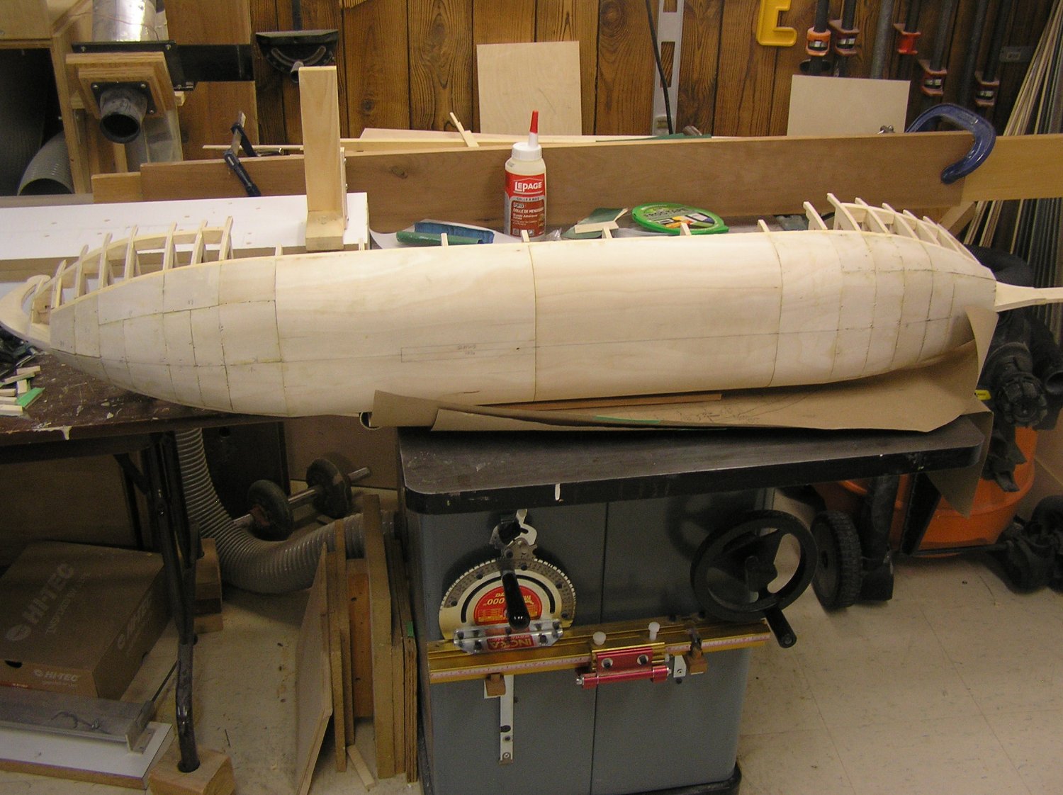
Hull cladding to the waterline now complete except for the last 1-1/2" at the stern. That's because I didn't carry the inner wale to the last bulkhead. Maybe I should have. I can't have a ply joint where there is no framing member, so either the aftmost piece will have to run from keel to deck, or the the piece above the wale from outrigger to stern will have an "ell" to cover that last part. I'm hoping that the part from wale to deck can be one big piece since the curvature is not as extreme as that below waterline. I recently noticed a mistake I made - I had the positions for the lower 22 oars marked on the keel but I seem to have forgotten that the 22nd upper oar is 5/8" aft of the 22nd lower oar and I placed a rib smack dab where that upper oar should project. 😭 I suppose the easiest fix would be to just omit the last upper oar, otherwise I need to cut the rib and frame a little box aft of it to support cladding. I'm taking a break for a few days now; partly because I'm not sure how to proceed from here, partly because the Admiral wants me to re-do the bannister on our stairs. 😉


- 536 replies
-
- 9
-
-
- Quadrireme
- radio
- (and 1 more)
-
I noticed one of the pictures at the start of the video depicted a ship with its bowsprit gammoning reaching to waterline. Good news as if I raise my SR's waterline to where I want, the same thing would happen. On the other hand I read somewhere that the gammoning slots could be placed higher.
- 2,699 replies
-
- 1
-
-
- heller
- soleil royal
- (and 9 more)
-
Wow! What a project. I couldn't follow all the French, it's been too long since high school, but I caught the gist. I think you're right to be concerned about the ship sitting in the rain all these years. 😬
- 2,699 replies
-
- 4
-
-
- heller
- soleil royal
- (and 9 more)
-
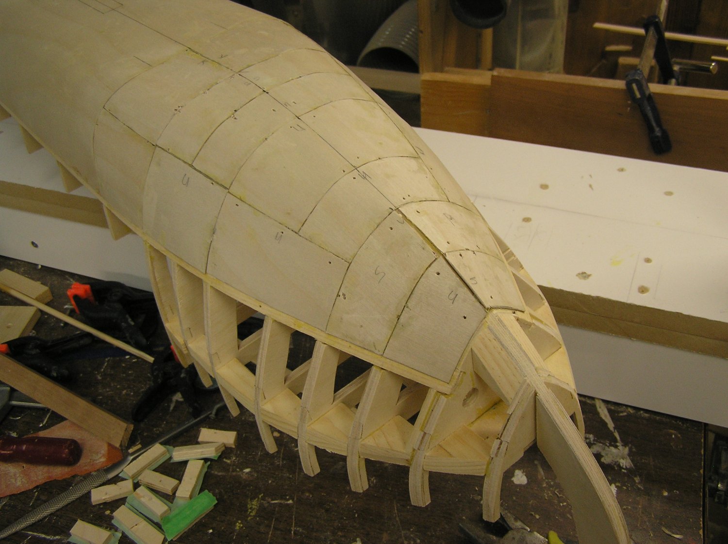
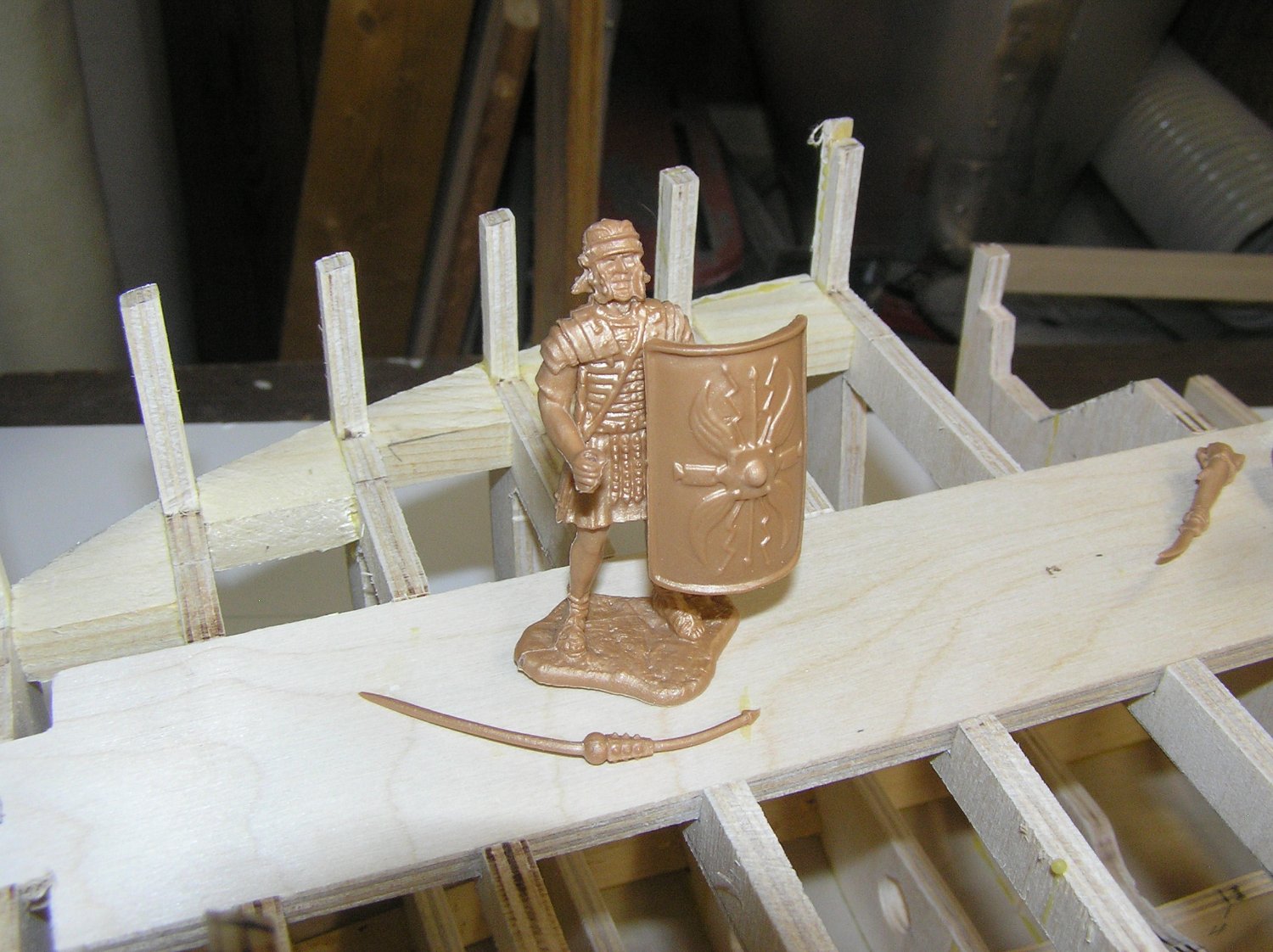
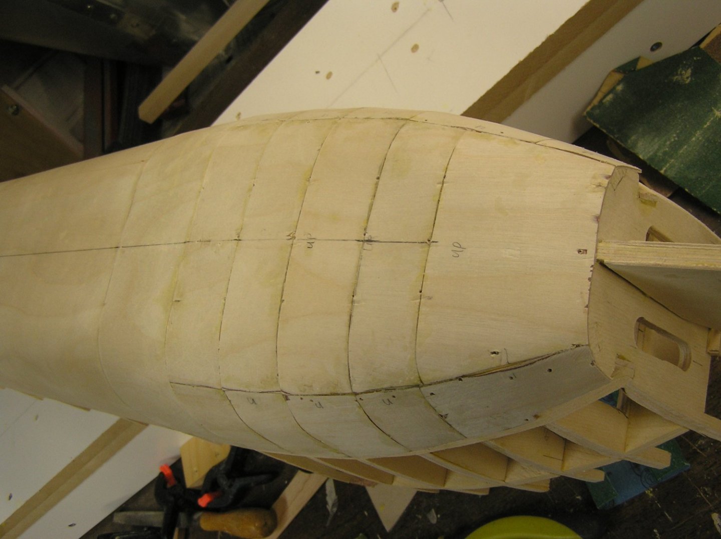
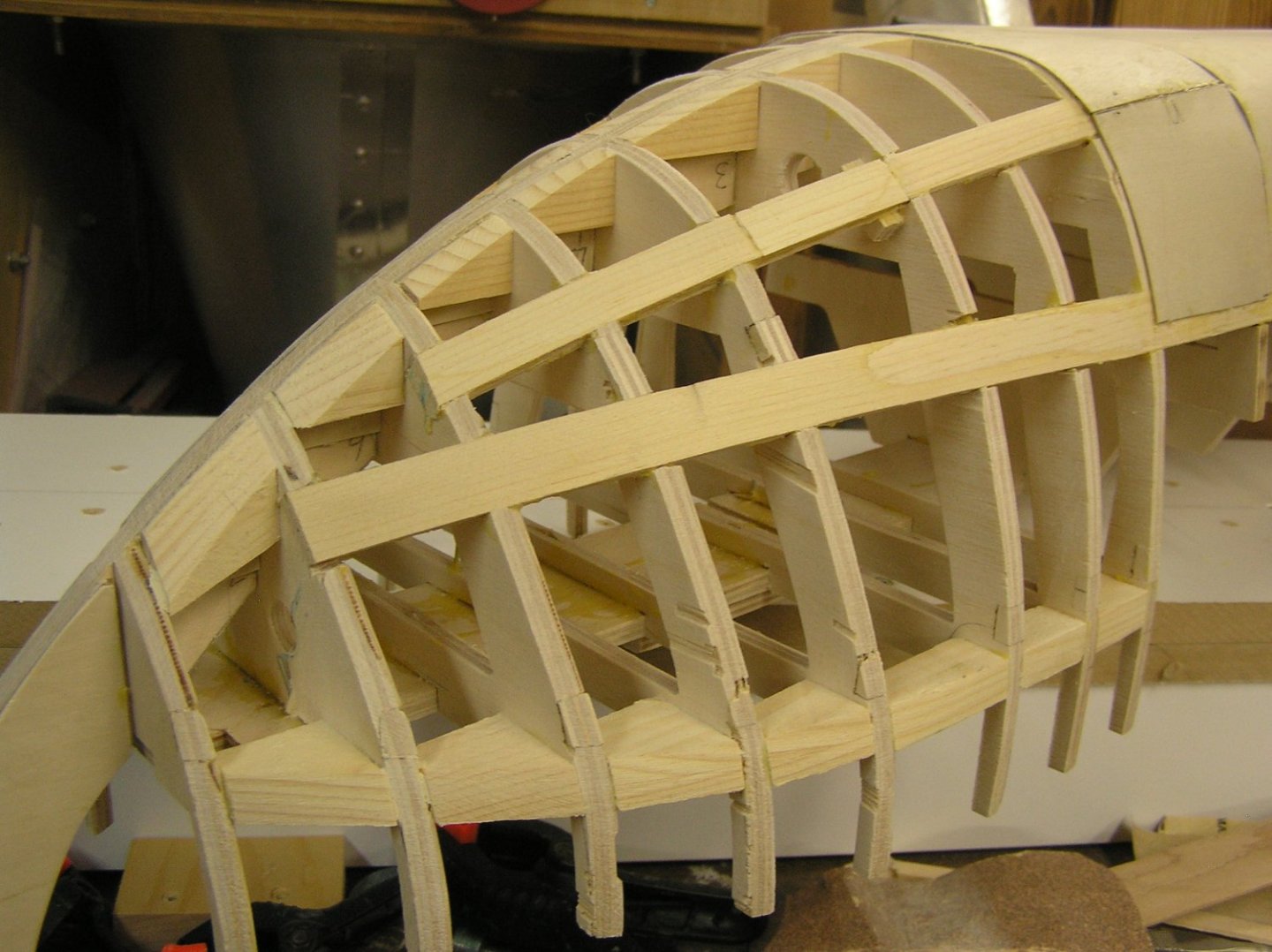
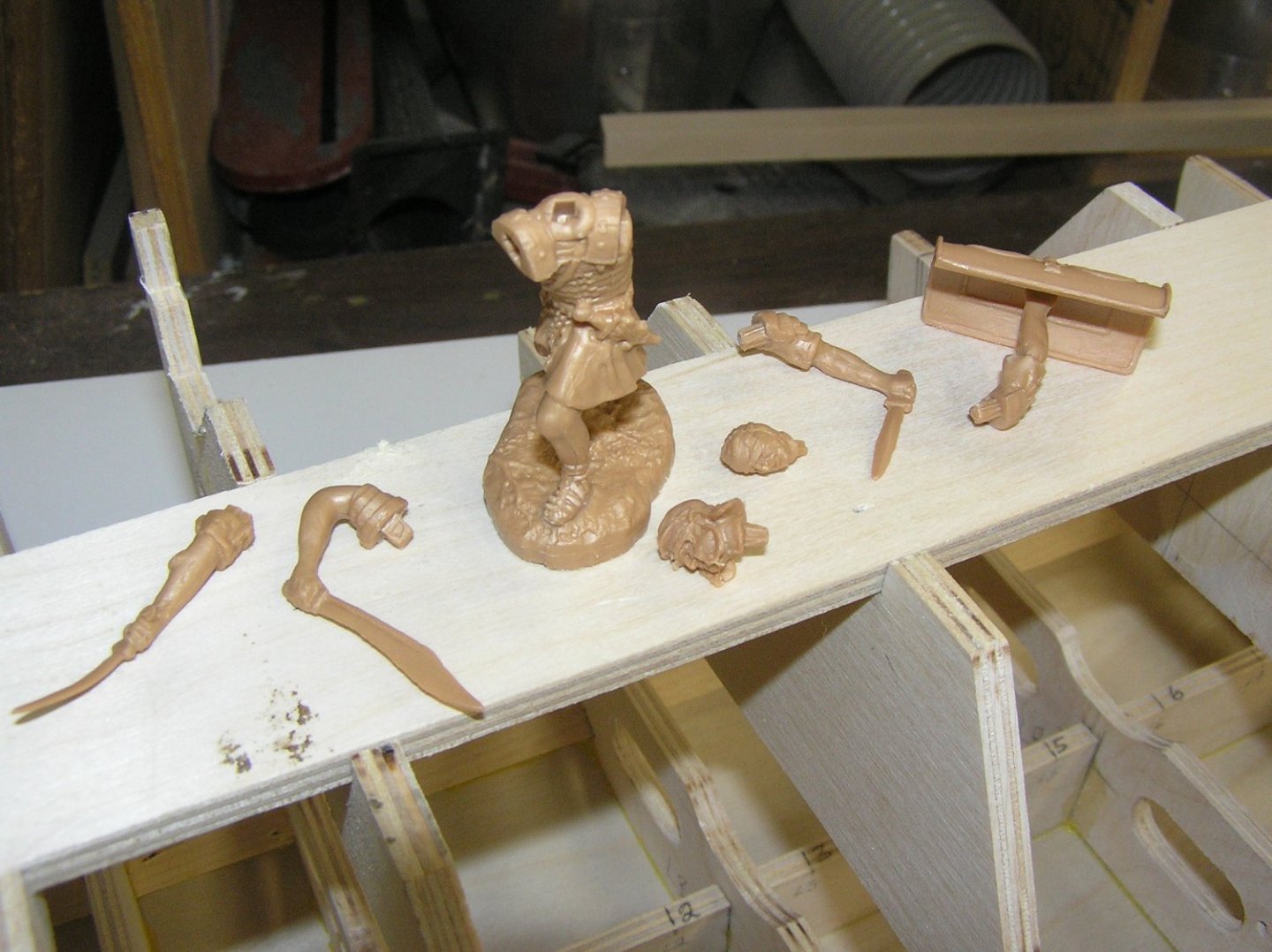
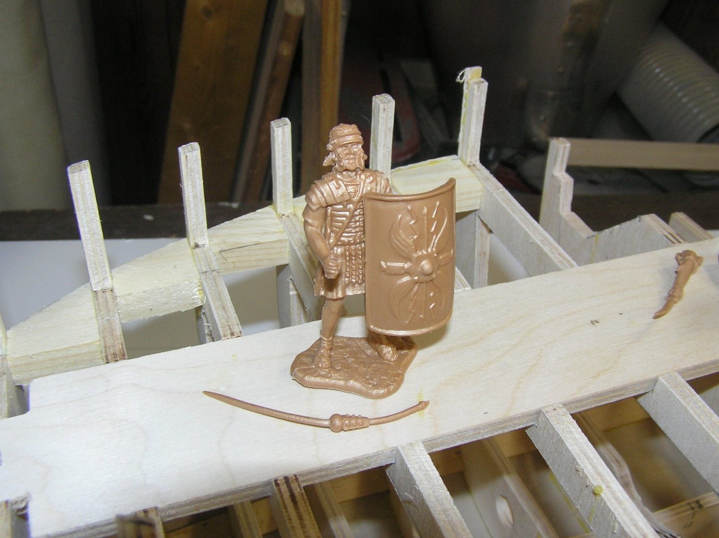
Got the bow skinned to waterline. Lots of pieces, lots of filling & sanding to come. First four pieces glued at stern. The stern will be pretty tedious as it's all compound curves so I may end up skinning each little framing space individually, or at best two adjacent. You can see where I plugged some old slots in the bulkheads after changing my mind about my method. And where I extended the bilge stringer to three more bulkheads. Oh, and my Conte Roman figures arrived. They're pretty nice. They're so detailed the guys with a foot off the ground even have the hobnails on their boot soles. 😲 I ordered a set in silver plastic figuring it would be easier to paint the armour on that base colour. Their web site showed they were in stock but that was in error, so Mr. Conte sent me the gold colour and kindly added an extra addendum set for free!! I have 25 guys, some of which have optional arms/heads/weapons to select and glue in place. I plan to learn about casting resin in silicon molds; I've seen videos where people sort of squeeze a casting out of the soft silicon mold which could not be removed from a solid mold unless it was two-piece. Unfortunately 23 of my men are holding a scutum (the classic legionnaire shield) but I do have one left arm with a hand on the end. Those holding a scutum have their left forearms terminating in a square slab, for want of a better word, at the back of the scutum. The only guys I want with a scutum are some marines standing with an optio addressing them. I also have two with the bearskin draped over their shoulders and heads; no use for them on a ship, but they're beautifully molded. More unfortunately, although advertised as 54mm they are actually nearly 60mm to helmet crest so they look a little big against my planned 1/32 scale bulwark height. I'd have a crew of 6ft-2in Roman giants! Sigh. Not sure whether to use them now but there are few other options and I am not capable of making my own men. This guy's pilum (spear) is bent. Conte advises dip in hot water then in cold while holding straight but a new brass one sounds better. I have no idea how they managed to mold his entire detailed body in one piece with the shield. Also no idea how I'm supposed to do detailed painting on his torso with the shield in the way! 😬 Probably will cut the shield off his not-detailed left hand. I'm not sure what type of glue to use on this plastic either. This guy can hold a gladius (Roman short sword) in each hand if desired. Wouldn't work out too well in a shield wall though; I would not want to be his neighbour! He has two right arms, two left arms, and two heads to pick from, one helmeted and one with a bandage wound round his head and over his left eye. Imaginative!
- 536 replies
-
- 8
-
-

-
- Quadrireme
- radio
- (and 1 more)
-
Beautiful work!! For what it's worth, I'd leave the top planking in natural. 🙂
-
Looking very nice! Those wood decks are beautiful, certainly a vast improvement on Revell's negatively-engraved deck.
- 248 replies
-
- 4
-
-
- Cutty Sark
- Revell
- (and 2 more)
-
Great work Daniel. I laughed at the shot of the tiny door to the seat of ease. We recently toured a WW2 submarine at Pearl Harbour and the watertight doors between compartments looked about that size compared to me (I'm 6'-4"). Getting through them was like limbo dancing. Crews must have been selected to be smaller men.
- 64 replies
-
- 3
-
-
- Revell
- Constitution
- (and 1 more)
-
Looks very nice to me!
-
Looking good. Does Revell provide any seats of ease for the beakhead gratings?
- 137 replies
-
- 1
-
-
- Golden Hinde
- Revell
- (and 2 more)
-
I'm dying to go aboard Victory, but don't want to fly all the way across the big drink to see her dismasted. By the time they finish this 20-year refit I'll be 74. I have my daughter's promise that if needs must she will go with me to push my wheelchair. Hoping it won't come to that! 😆 I did see her in the early 80's but at that time the foremast was unrigged and the bow was enveloped in scaffolding and blue tarps. 😭
- 248 replies
-
- 1
-
-
- Cutty Sark
- Revell
- (and 2 more)
-
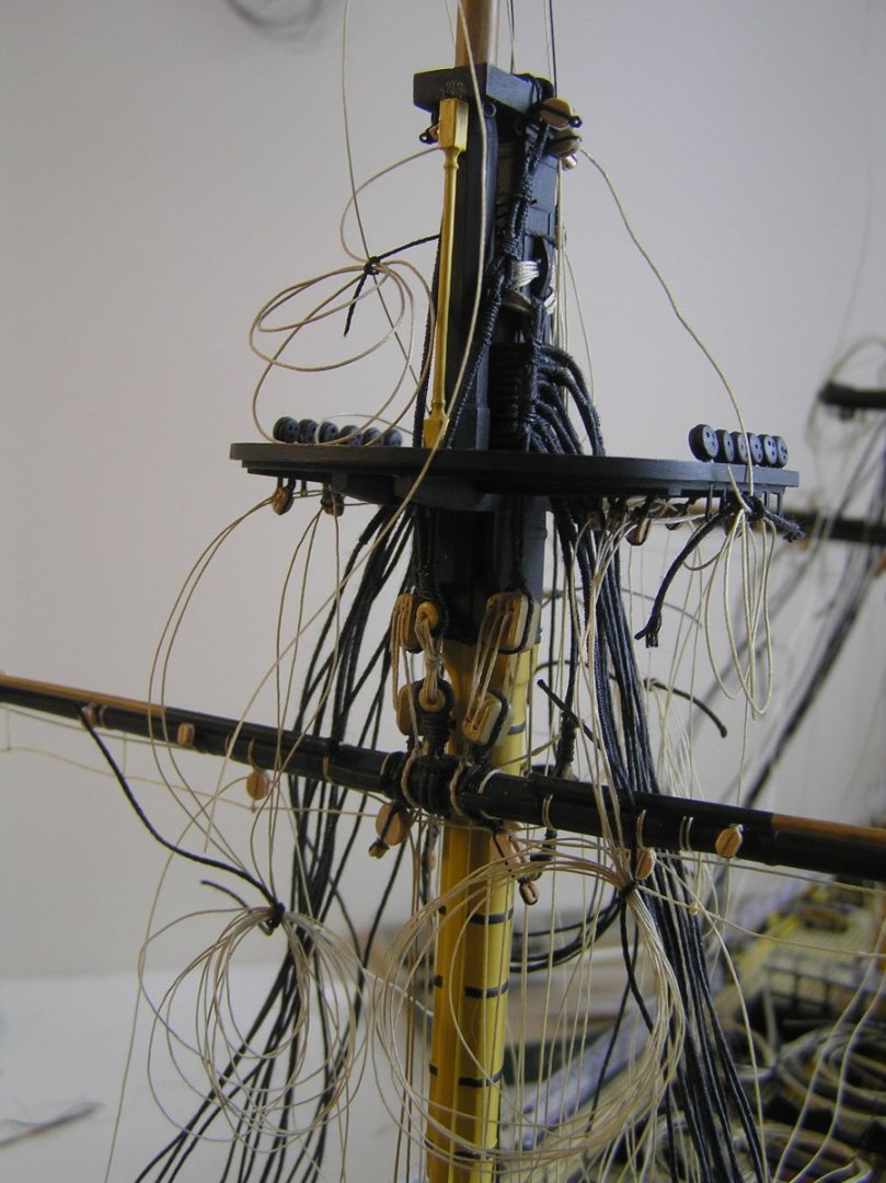
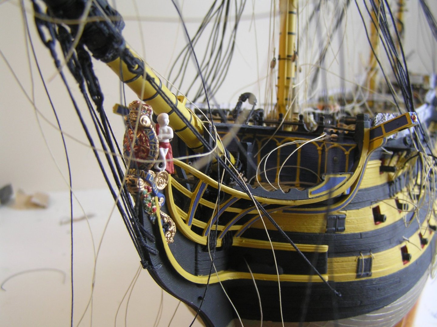
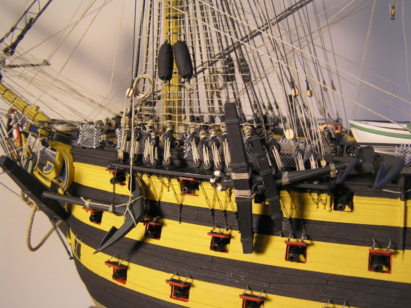
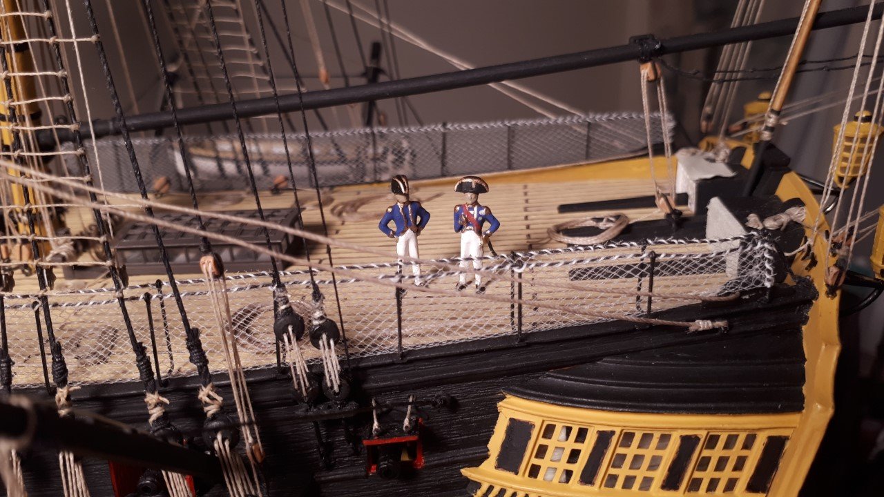
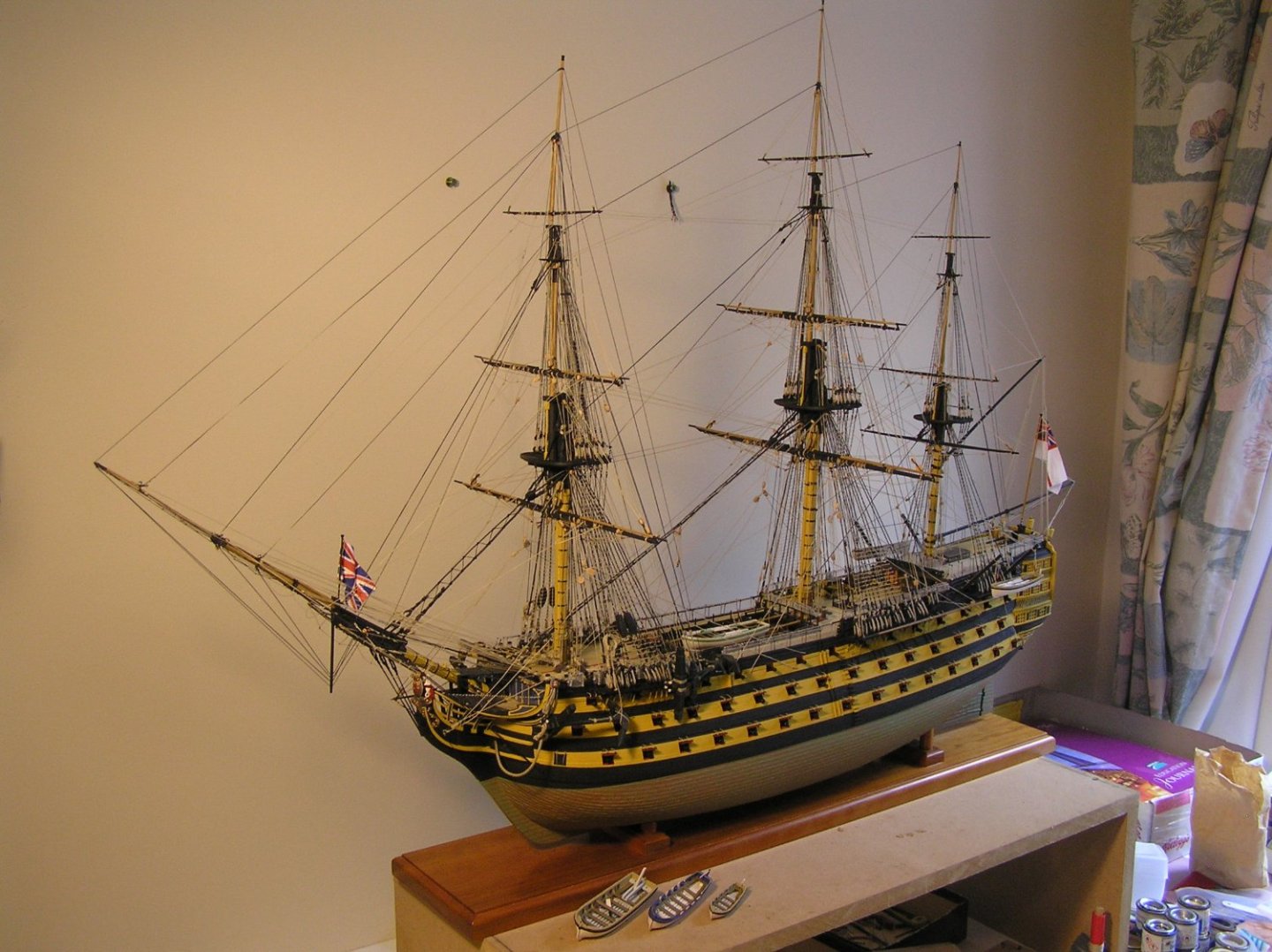
I too returned to the hobby after making several ships, including the CS, in the 70's. It has been a source of much satisfaction. To whet your appetite for the big Heller kit, here are a couple of in-progress shots of my Victory to show what can be done with plastic. I bought it in 1982 and it sat on a shelf for decades. There are several sheets of brass etch enhancements available now; I bought two of them. Most people take years for her, I took five working on and off. Bill97 built her very quickly, see his log.
- 248 replies
-
- 4
-
-
- Cutty Sark
- Revell
- (and 2 more)
-
Vitus, if you become hooked on ship models, you might like to try a Heller Victory which is hands down the best plastic sailing ship model extant. She is well worth the bother of serving shrouds and stays as appropriate.
- 248 replies
-
- 1
-
-
- Cutty Sark
- Revell
- (and 2 more)
-
Underhill's excellent book is entitled "Masting and Rigging the Clipper Ship and Ocean Carrier". It has many excellent diagrams of ironwork on yards and masts, and rigging details but is not specific to CS. I believe there is an AOTS Cutty Sark (may be wrong). There is also a little book by Noel Hackney on CS; I've never seen it but his book on Victory is very good, though under-rated in my opinion. By the way I see no one answered your question about the bars running along the tops of the yards (or did I miss it?). They're called jackstays and the head of the sail was attached to them, not the actual yard. Good luck with your build. She's a beautiful ship. This is the 1/96 scale model, correct?
- 248 replies
-
- 4
-
-
- Cutty Sark
- Revell
- (and 2 more)
-
Very nice Shields 2.0 Glen! Regarding plastic rivet heads, I thought they might work for a Soleil Royal build with wale bolt heads but the smallest I found with a cursory look were 0.040" DIA probably too big for your SIB's.
-
Dave, if you want to see an impressive ship, check out "Royal Clipper" which is a modern 5-master inspired by Preussen, and which offers cruises in the Med or Caribbean. I mentioned early in this log that we took a week's cruise aboard her. Awesome!! (I have no association with Star Clippers).


-
Hi Dave; When I built my Revell Cutty Sark in the 70's as a naive teenager I just used model glue to attach all my "coils" to belaying pins. That hasn't failed either which is almost unbelievable to me! I used CA on my Heller Victory build too, even though I read some warnings on MSW about using CA on rigging. Some people are quite adamantly against it but my Victory seems ok so far. I sure would like to get on and finish this build (I know exactly where to display her). I've been seduced by another build, a Roman galley for radio control, after interrupting Preussen to experiment on oar drive mechanisms. I don't see a log for your Pamir, but I find the search engine a bit problematic; I'm sure it's just me. Do you have one....if not I'd love to see your work! Not too many windjammers hereabouts! Regards, Ian
-
Could double-sided tape have held the pre-severed and filed flat heads while you painted them?
-
Mon Dieu! Bravo mon ami!
-
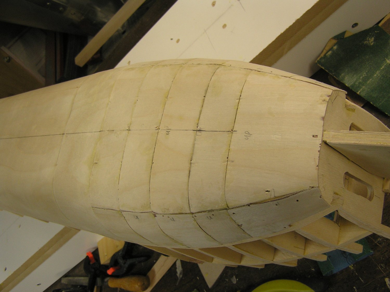
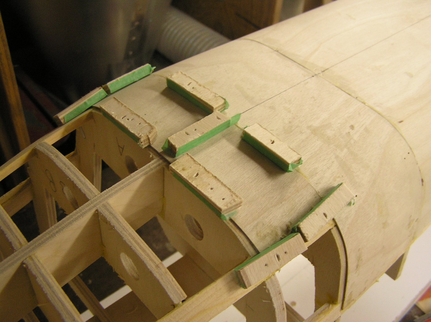
As I start the bow skinning I have to use smaller pieces of ply to divide the compound curves into smaller, weird quadrilaterals and trapezoids. Spacing between framing members is also smaller so I can't fit clamps to the inside, therefore I started using small ply battens and air-nailing temporarily to the frame through the ply. I put masking tape on the battens so they wouldn't end up glued on. The first couple of pieces went ok but on the third most of the 23ga pin nails snapped when I tried to pry them back out. I've reverted to 18ga which won't snap, but could splinter bulkheads if I miss centre, sigh. Trying to shoot most of them into wales and stringers. It's not a pretty sight and it's too bad the resulting holes will be bigger than the 23ga, but I'm sure the filling/smoothing stage will hide all sins. Here's a piece I just added. It's slow going: template the next piece using clear vellum paper, bandsaw out, test fit and adjust, glue on, wait 25 minutes to remove the battens, pull any remaining 18ga brads, scrape off glue squeeze-out before it fully sets, then on to the next.

- 536 replies
-
- 4
-
-
- Quadrireme
- radio
- (and 1 more)