Ian_Grant
-
Posts
2,156 -
Joined
-
Last visited
Content Type
Profiles
Forums
Gallery
Events
Everything posted by Ian_Grant
-
 Thanks Steven! That does help, a lot. I can imagine the mast pivoting aft since the archery tower is forward. Actually, it would be cool to make it hinged so as to lower it when "drydocked". Will see what I come up with.
- 536 replies
-
- 3
-

-
- Quadrireme
- radio
- (and 1 more)
-
Nice model! I'm interested in the mast step; I'm making a Roman galley and I'm not sure how to depict this. I am sure it didn't drop down through a hole in the deck or they'd never be able to pull it vertically out by hand. It seems your crew hoists the mast to vertical, and lashes it to the sturdy upright? Would that sort of thing be applicable to my galley, does anyone know? I have several books on galleys but this detail is not covered as far as I have found.
-
Looks great! Is it possible to print this at 1:180 scale?
-
She looks great! I just scored this kit for free at a model club meeting; someone had passed away and his wife gave a club member three ships to bring in to our last meeting and give away to any interested members - two built tugboats and Calypso with very little done. I don't have time to build her right now; perhaps my wife will end up passing it along again after I pass away! 😏
-
Bill, I can't imagine them leaving a pile of wood on deck as a source of flying splinters in an action, given that they towed or abandoned the boats for the same reason. Spare spars yes, lashed near the centreline. I planned to just omit the wood. If I ever get there. As for the sponge tubs, well, they were full of water and probably did double as fire buckets so I wouldn't worry about changing them. Hope my SR looks as nice as yours; again, if I ever get there.
- 1,508 replies
-
- 3
-
-
- Le Soleil Royal
- Heller
- (and 1 more)
-
According to the English translation page on my old instructions, that barrel is a matchtub ie for lit matches I presume. Quite why there would be only one is another question. Looking splendid Bill !!!
-
Hi David; thanks for the reply. Yes, it is something to ponder. I thought about cloth and resin over the smooth hull before applying walesetc; on the other hand this is a made-up hull (ie, there were no plans available) and my hull displacement calculations and estimated total weight were a little uncertain so I'm trying to keep weight down. In my case, the skin is all 1/32" plywood with joints over framing members; if it was planked I'd definitely use cloth and resin on the exterior, and resin on the interior. I hadn't heard of TotalBoat before, I've always used West System which as far as I know only has one type of resin. Thanks for the reference; I will read up on TB's resin varieties. I notice that the finishing resin has wax in it but they say it can be painted; that's a little unusual. Will post later and report on whatever I end up doing.
-
Thank you. 🤙
-
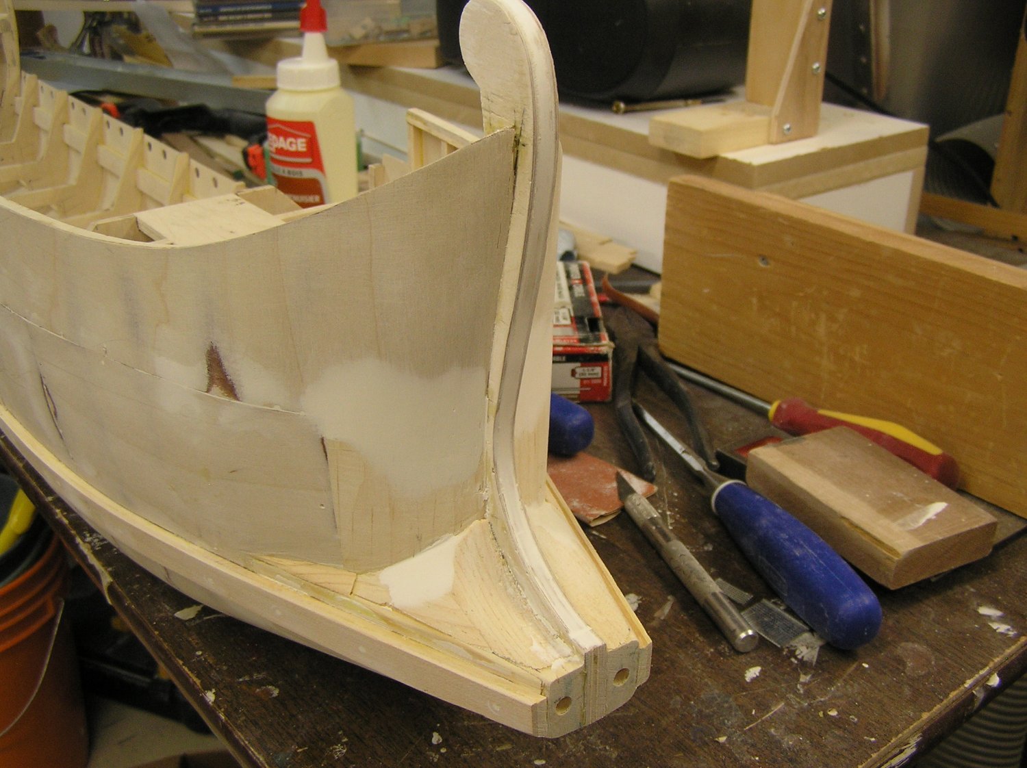
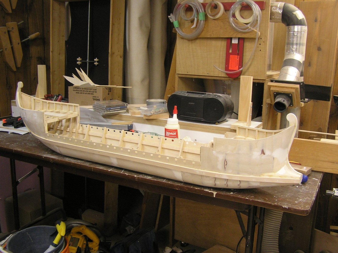
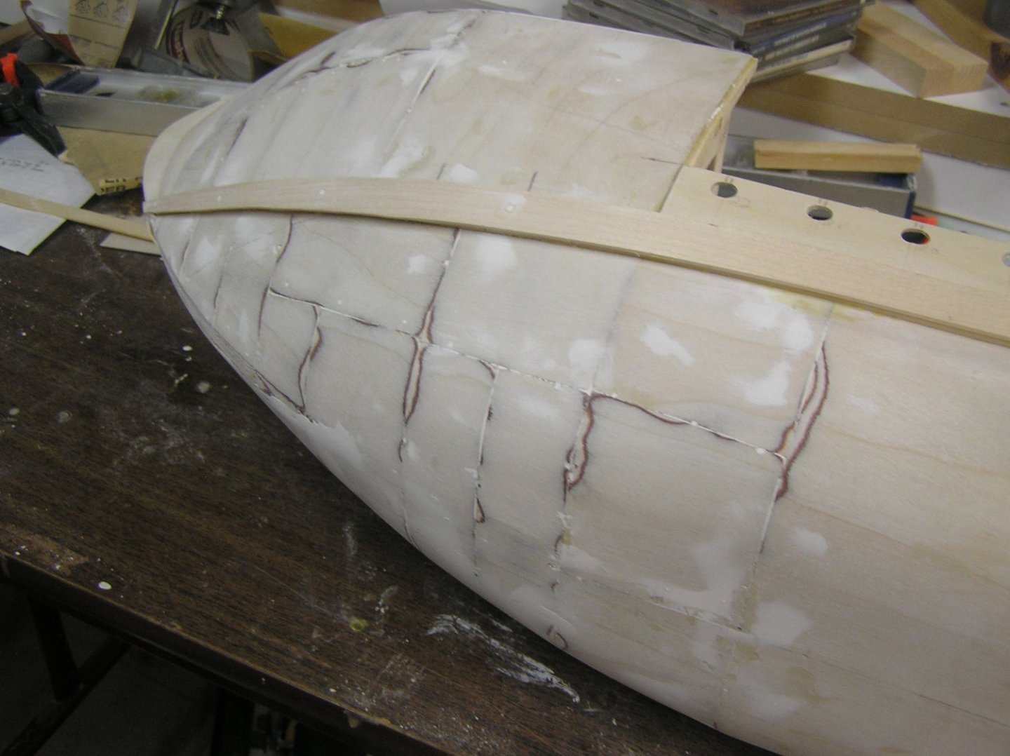
We're off on a bucket-list trip tomorrow so I thought I'd post the ship status. I added the thicker plywood containing the ports for the lower oars, and also the main wales. Transition from the ram up front getting more refined. The extreme stem is now a flat surface with two holes for aluminum rod "pins". The actual ram will be 3d-printed with matching holes. The real ship's wales went right into the ram casting to distribute the shock of impact along the entire fabric of the ship. This will be simulated with angled projecting "ears" on the ram to match the wales (same for the stem). Next step is to add the external keel. Too bad as the flat bottom has been handy to have, but I don't want to be adding it after the perhaps fragile outriggers are on the sides. Wouldn't mind painting the bottom too, before adding the outriggers. I made a start at sanding/filling. Hull actually feels pretty good considering. Does anyone have a recommended product to "caulk" the cracks where two surfaces meet? eg the wales and the hull? On house trim I'd just use latex painter's caulk and be done with it. Not sure if this would be suitable on a model boat on water........ Hope to hell this thing actually moves on the water!!! 🙄 😬

- 536 replies
-
- 9
-

-
-
- Quadrireme
- radio
- (and 1 more)
-
First layer aesthetics don't really matter. Yours looks clean and fair, so it's great!
-
It's only that valuable if someone pays that for it. 🤪 There are ridiculous price ranges on amazon.ca for specialized books too, ranging from reasonable to astronomical. Always bugs me.
-
On my model, I frapped the guy pendant and flying jibboom guy tackles around themselves since they are rarely adjusted. I belayed the traveling guy to a timberhead on the front rail since it would need to be adjusted every time they moved the jib traveler. Made sense to me. 🤔 Note Longridge calls it the "traveling guy" in the text describing the guys (pp 227-228) but it is labelled as the "jibboom guy" on pg266.
-
I forgot to mention that successive seizings move gradually further aft as the shrouds move higher up the mast, to keep things neat. It's noticeable in the picture.
- 248 replies
-
- 1
-
-
- Cutty Sark
- Revell
- (and 2 more)
-
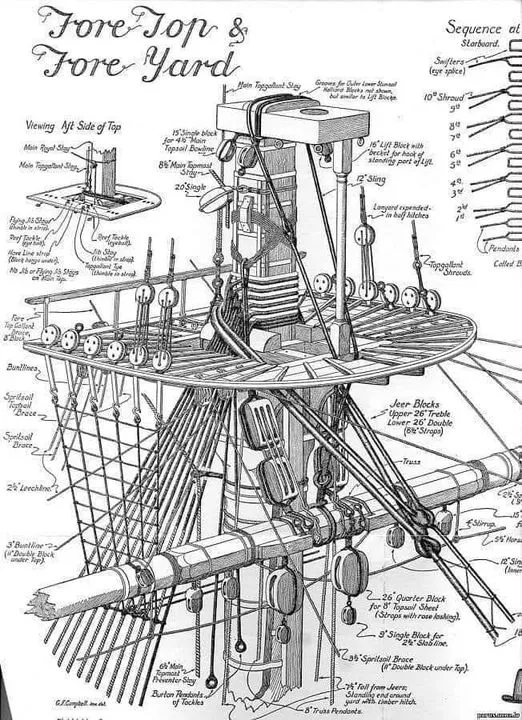
Hi Vitus, A length of thread is looped around the mast head, above the top. The resulting two lengths are clenched together tight against the mast with a seizing very close to it; that gives you a shroud pair. Usually the starboard forward pair is first, then the port forward pair is wrapped around the mast, seized, and pushed down against the first pair, from above. Then the starboard 3rd and 4th shroud, and so on. At the end you have a series of wraps around the mast stacked in a neat vertical array. Have a look at the picture below, from Longridge. The shrouds are seen just above the top, in two colours to indicate the alternating port/starboard shroud pairs. This is an 18th century ship ("Victory", in fact), but this aspect is the same even for wire rigging.
- 248 replies
-
- 3
-
-
- Cutty Sark
- Revell
- (and 2 more)
-
Hi Bill, your modified show guns with new wheel and trunnion positions look great! Nice job.
-
Words fail me......stupendously imaginative scene....water looks fantastic, love the wave crest frothing....bottle mouth dripping looks great....how can you ever top this, I don't know.
-
Hi members, I'm making a model for RC operation on the water. I skinned it in plywood with all joints on framing; I don't want to f/g the outside. I do plan to spar varnish before scuffing and painting. There are outer wales and a few trim pieces to apply to the outer hull. I don't want cracks to show along the their edges. If it was room trim, I'd use painter's caulk then paint over. Can I use this for a hull which will see water? Is there something better?
-
Nice work, Rookie.....🤙
-
Yes that's correct. I would ignore the Heller rigging notes judging by that new diagram. I know I ignored their notes in my old Heller Victory instruction sheets. Longridge is your bible for Victory.
-
The stays through the dolphin striker are, from top down, the inner martingale (Longridge pg 227), outer martingale (pg227), flying martingale (pg 227), and fore royal stay (pg 224). The martingales all belay with purchases to the port or starboard knighthead, each of which has three eyebolts on its front face. See Plan 10 on pg 266 for notes. Plan 10 shows that in addition to the martingales, the fore topmast stay, fore topmast preventer stay, and fore topgallant stay also belay on the knightheads. Longridge states that the fore royal stay can belay to the forestay collar, or a knighthead; but as he already has three lines to each knighthead he apparently decided it must belay to the collar.