Ian_Grant
-
Posts
2,156 -
Joined
-
Last visited
Content Type
Profiles
Forums
Gallery
Events
Everything posted by Ian_Grant
-
 Whew! Hope your drug arrives quickly, and that you are home soon! 🤙
- 248 replies
-
- 1
-

-
- Cutty Sark
- Revell
- (and 2 more)
-
My opinion - that ring is too big. Just my opinion.
-
I think that sheet is a "Hellerism"; running it past five cannons through the centres of the openings seems crazy. On the other hand you'd want a lot of length in order for many men to clap on when hauling. On yet another hand they wouldn't be able to with cannons standing there. I half remember someone talking about changing some of the belay points on his SR, and that in the instructions one of the big kevels is empty and made more sense to use than what the instructions stated. Sorry I can't be more specific, I of course haven't started this ship yet.
- 1,508 replies
-
- 1
-

-
- Le Soleil Royal
- Heller
- (and 1 more)
-
Sorry to hear that; get well soon! To seize the a shroud at a deadeye, I wrap it round at the correct length, then clamp it at the deadeye edge with, again, a mini toothless alligator clip. I then apply the seizing thread with an overhand knot; it's thin enough to slip in between the clip and the deadeye. I then wrap both legs of the seizing around to the back of the deadeye and do another overhand knot. Then remove the clip and again wrap the two shroud threads and one leg of the seizing using the other leg, finish with an overhand knot or two, dab of glue, and trim the ends. Not really cricket compared to reality but at 1/100 it looks fine to all but the most discerning modelers.
- 248 replies
-
- 1
-
-
- Cutty Sark
- Revell
- (and 2 more)
-
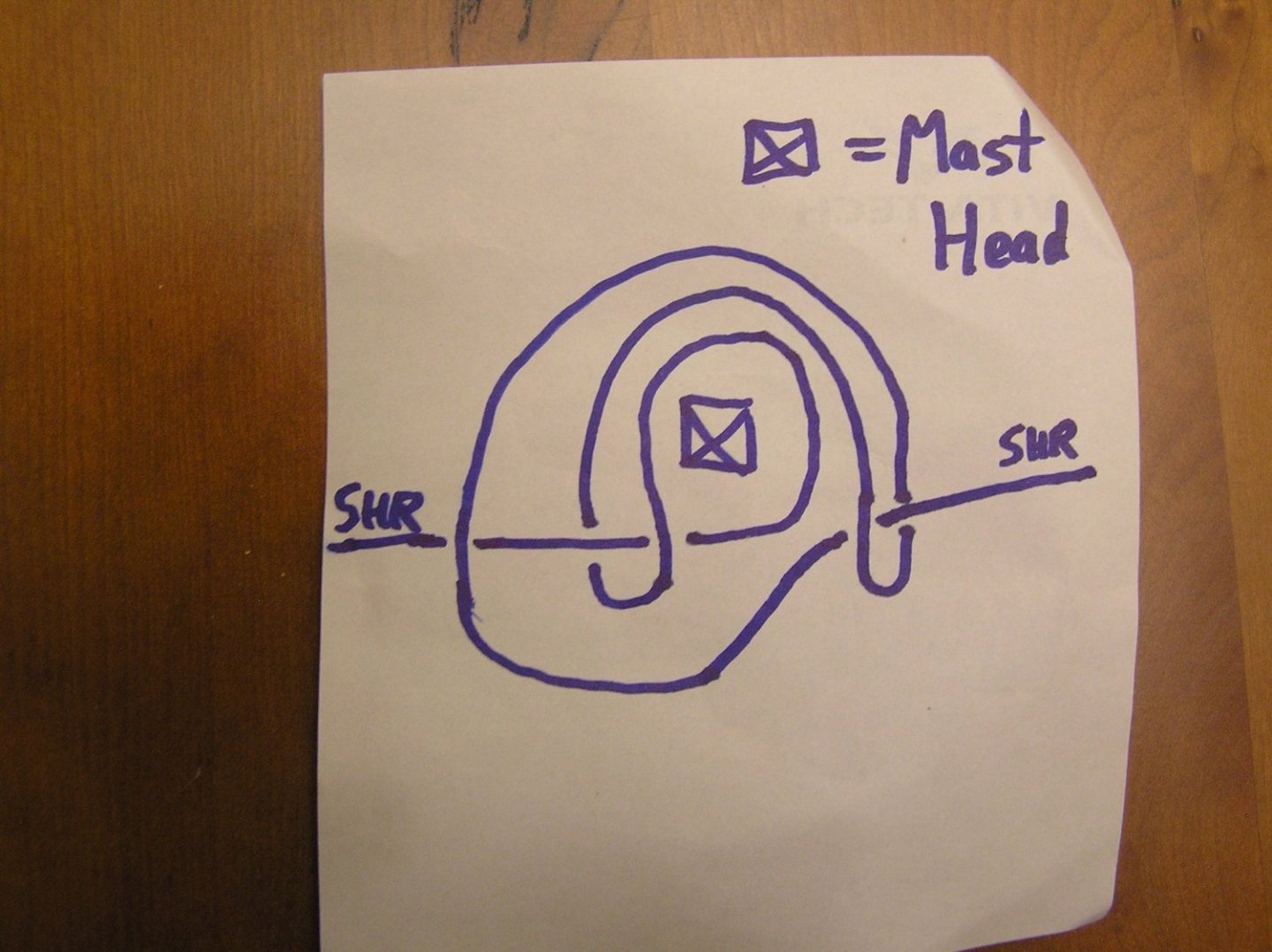
You're allowed to cheat at 1/100 scale! I start a seizing by tying an ordinary overhand knot, then use one leg to wrap both the other leg and the lines being seized, ending in another overhand knot. A spot of glue, snip the ends and you're done. One can sometimes seize the shroud pairs off the ship, around a suitable diameter dowel, then slip them over the mast head before adding the cap, be it lower or topmast. If one needs to seize at the masthead, I use a mini alligator clip (the type with no teeth) to hold the loop together while I seize. For singleton shrouds (called "swifters" I believe), you can cheat (again) by using the knot below to add both sides at the same time with one length of thread. Where they cross, I've interrupted the one that is below the other. This looks very effective on the mast, much like two properly formed swifters. By tugging at the two loops as you tighten it you can "move" the shrouds forward or aft on the mast. Thanks to "Blue Ensign" who published this on the old Pete Coleman Victory Model website.
- 248 replies
-
- 3
-
-
-
- Cutty Sark
- Revell
- (and 2 more)
-
Did you mean the seizing of the shroud pairs at the masthead? Or the seizing at the deadeyes?
- 248 replies
-
- 1
-
-
- Cutty Sark
- Revell
- (and 2 more)
-
Thank you Marc. She's looking pretty rough to this point; I just hope I can do the finer work and the finishing with more elegance.
- 536 replies
-
- 3
-
-
- Quadrireme
- radio
- (and 1 more)
-
Soleil Royal by yancovitch
Ian_Grant replied to yancovitch's topic in - Kit build logs for subjects built from 1501 - 1750
I agree. That hull is beautiful! As are the masts and rigging, obviously. -
Kit bashing an x-wing fighter..... 😃 You've come a long way Bill!! 😏
- 1,508 replies
-
- 1
-
-
- Le Soleil Royal
- Heller
- (and 1 more)
-
Yes, they do add a lot to the model. I remember being thrilled too. Good job taping the bee lines! Nice model!
-
Oh, never thought of that. It's British slang I picked up from my Scottish parents, along with many old Scots words like fankle, glaikit, drookit, besom, teuchter, dreich, mauchit, fouter, eejit,.....I could go on and on......I actually use them occasionally......usually to blank stares..... You can google their meanings if you like. That last one is obvious. 😃 My dad used to employ one of my favourites, which can replace GodDammit! or What In God's Name....."In the name of the wee man!!" 😄
- 536 replies
-
- 2
-
-
- Quadrireme
- radio
- (and 1 more)
-
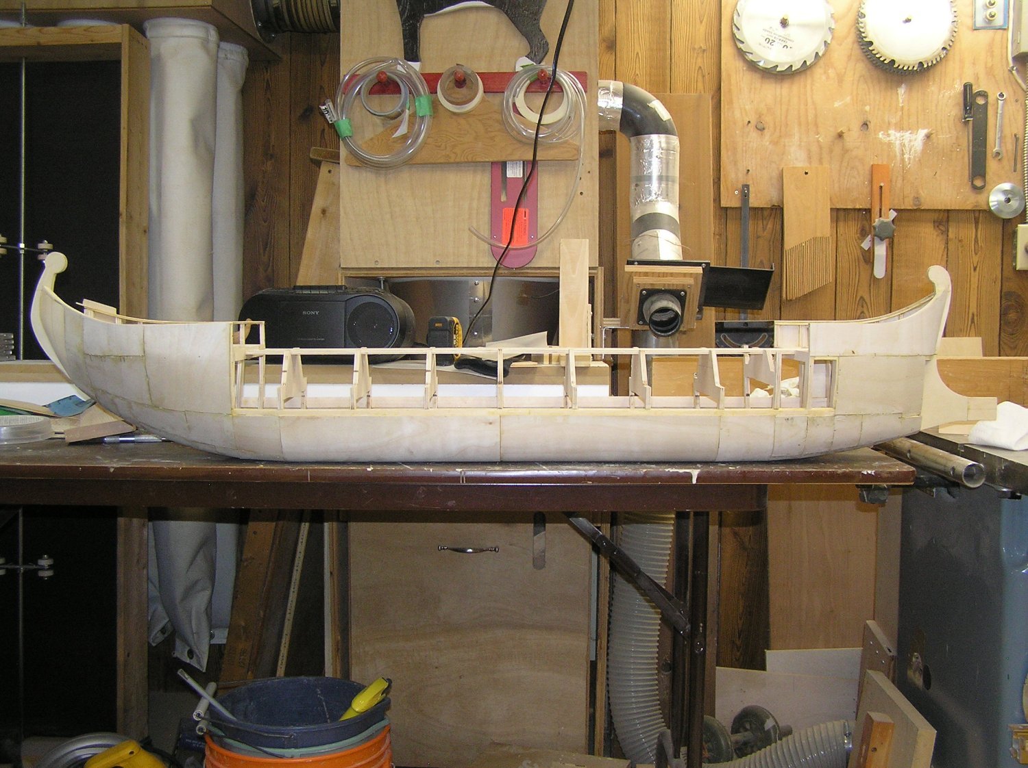
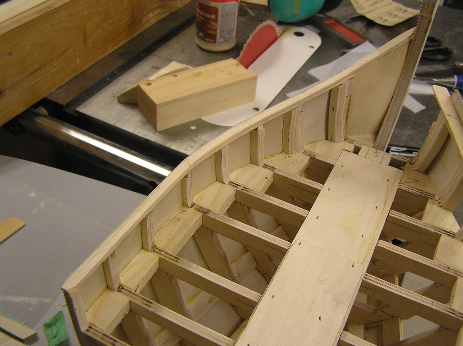
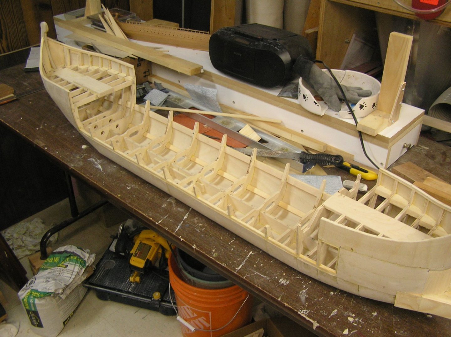
Got almost all the skinning done and closed in the stern with solid both sides. I then decided it was the moment of truth; cut away all the midships bracing along the top to allow the outriggers to be started. My fear was there might be unbalanced tensions in the hull, and since the entire midships is only skinned to waterline and looks really low compared to the ends, there might be a "twang" as the whole hull twisted 10 degrees or something. But it was uneventful. One can more readily imagine now the oar mechanisms being dropped into the hull. I've been adding solid at the bows to blend into the ram, but made a dog's breakfast of it. 🙄 Without really thinking I made the lower blocks just big enough to fill the open cavities, but they need to sweep further back to look right against the hull's taper. This means matching the curving hull on two axes as it overlaps. 🤔 I ended up adding various weirdly curved fillets with various pieces. What a mess! You can see in the bow picture I cleaned 'em up a bit, but they're staying flat on the side for now until I get the main wales installed, running to the ram. Then I will blend the lines better. Speaking of the wales, I can't install them until I have the plywood strips with the holes for the lower oars installed, since the wales cover up the joints along these strips's bottom edges. So that's the next job. Oh, I also did some sanding of the plywood joints. It actually looks pretty good in terms of having pretty fair hull lines. Smoothing the joints mostly reveals an irregular strip of the darker second ply layer along each side of the joint. That's ok as all joints have framing members inside.
- 536 replies
-
- 9
-
-
- Quadrireme
- radio
- (and 1 more)
-
The Heller Victory, whose fore and main lower ratlines span 9 or 11 shrouds each, requires about 3000 clove hitches to rattle down completely. That idea of pushing the ratlines through the shroud threads with a needle could save time.
- 248 replies
-
- 1
-
-
- Cutty Sark
- Revell
- (and 2 more)
-
Elder, Any sailing RC model has to be designed with the "scale problem" in mind. At 1:8 scale you have a hull 1/8 as long, with 1/8EXP2 ie 1/64th the sail area, and 1/8EXP3 ie 1/512th the displacement. In other words you have 8 times the sail area relative to the displacement, with all the negative implications on stability. This is why scale sailing models almost invariably have fin keels with a streamlined lead-filled bulb on the end. Some builders make the keel detachable for transport and/or for out-of-water display. I'd be very surprised if your model would be stable if faithful to the original hull, even with the tiny stub keel crammed with lead. I highly recommend the soft-cover book "An Introduction to RC SCale Sailing Models" by Phillip Vaughan Williams, which covers all aspects including stability, hull making, rigging, and sail winch control systems for even the most complex full-rigged models. Look forward yo your build!
-
Cool! I may experiment with that to rattle down my "Preussen", whenever I get back to her. Occupied with another build right now.
- 248 replies
-
- 1
-
-
- Cutty Sark
- Revell
- (and 2 more)
-
The usual way to rig the shrouds with deadeyes is to attach the lower deadeyes, with method depending on the ship. On earlier ships they'd be attached to the chainplates. If I understand you correctly, you plan to attach them to evergreen strips which will then be hidden beneath the rails? Sounds ok. To rig the shrouds, seize them in pairs around the masthead. If you are feeling ambitious the portion of the shrouds wrapping around the mast can be served. Once all the shrouds are attached at the masthead, the upper deadeyes are seized at their lower ends. The trick is to maintain a constant separation between the deadeye pairs. There are many examples here of little jigs with pins that insert into a hole in each deadeye to hold their spacing as the shroud is wrapped around the upper deadeye's groove, and seized in place. The final step is to reeve the lanyards. I understand you are trying to reeve the lanyards first to make it easier but I don't think it is often done. One reason for this, perhaps less critical on the CS as opposed to an 18th century warship with many more shrouds, is that as you progress aft, the changing angle of the shroud wrt vertical means that a constant vertical offset between deadeyes needs an ever-increasing length of lanyard between them. Hard to explain in words but I hope you see what I'm getting at. The ratlines are painfully added manually, once all shrouds are in place, via many many clove hitches and a striped paper jig behind the shrouds to ensure constant ratline spacing. Prepare to spend hours and hours. As an interesting aside, Heller kits like Victory and SR provide the deadeye pairs set a distance apart by the sprue with the idea being that you can easily reeve the lanyards first. But then, given the nature of two-part molds, the upper deadeyes cannot be molded with the groove so they are nearly impossible to rig; most builders buy after-market wooden deadeyes. I did for my Victory. Heller also provides a "shroud jig" which purportedly simplifies forming the shrouds and ratlines off the model then attaching. Few builders use it; most do it the manual way as above.
- 248 replies
-
- 1
-
-
- Cutty Sark
- Revell
- (and 2 more)
-
Glen, definitely the strangest, but also one of the best, and certainly the most imaginative, build I have ever seen! Congratulations, it is wonderful! I love the eyes! 👍👍 🤙 It's two thumbs up from critics.........
-
Checking my old CS rigging sheet, I see the way the stays are wrapped round at the masts is wrong. Diagram 1 shows the lower stays wrapping around the base of the topmast...WRONG...they should wrap around the back of the head of the lower masts they are purportedly bracing. The stays may pass over the front rims of the tops, or they may pass through the lubber's holes to get a straighter line; I don't know which scheme the CS employs. Same story at the crosstrees - wrap around the topmast head, NOT the topgallant mast base. I see to my regret that the teenaged me followed these instructions. Maybe I should do another CS, with modern wood decks. If you have Underhill he has a myriad of rigging details.
- 248 replies
-
- 1
-
-
- Cutty Sark
- Revell
- (and 2 more)
-
The old instructions' numbered rigging steps are in a sensible order. Generally work from the centreline out, from bottom to top, and fore to aft. I like to attach lines which terminate on the deck (as opposed to gunwales) early on then rig them in reverse ie pass them up masts through whatever blocks and tie off up there; my big clumsy hands have problems reaching in through rigging to tie off a new line at the deck.
- 248 replies
-
- 1
-
-
- Cutty Sark
- Revell
- (and 2 more)
-
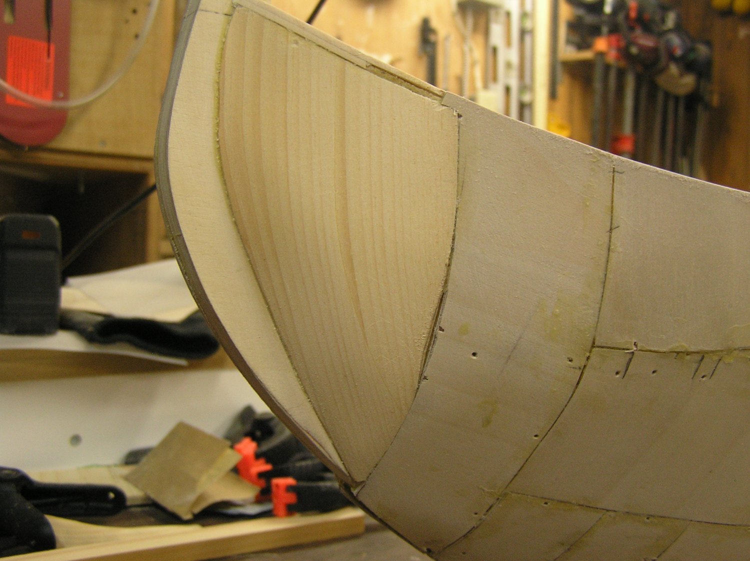
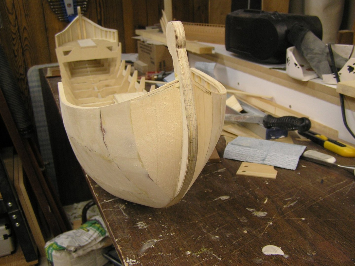
Thanks Pat! I cut bulkheads at bow and stern using half-hulls I carved then sliced up for patterns. The fairing was pretty good for a made-up hull from no plans, but yes there was a bit of fiddling in several places before skinning. I noticed the stern bulwarks don't appear parallel in the photo so I checked - the difference is real. Will need to sand the top rail on one side or the other depending on where the error is. In the end, the 1/32" ply is so thin that there are places where it sort of flowed in straight lines from bulkhead to bulkhead, the dreaded "starving cow" effect. Will have to see if I can sand to better curves - not much leeway to sand the thin ply though, and I don't want to be plastering large areas with filler then attempting to blend in. 😬
- 536 replies
-
- 3
-
-
- Quadrireme
- radio
- (and 1 more)
-
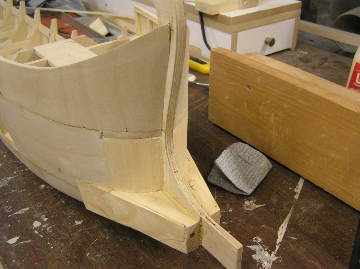
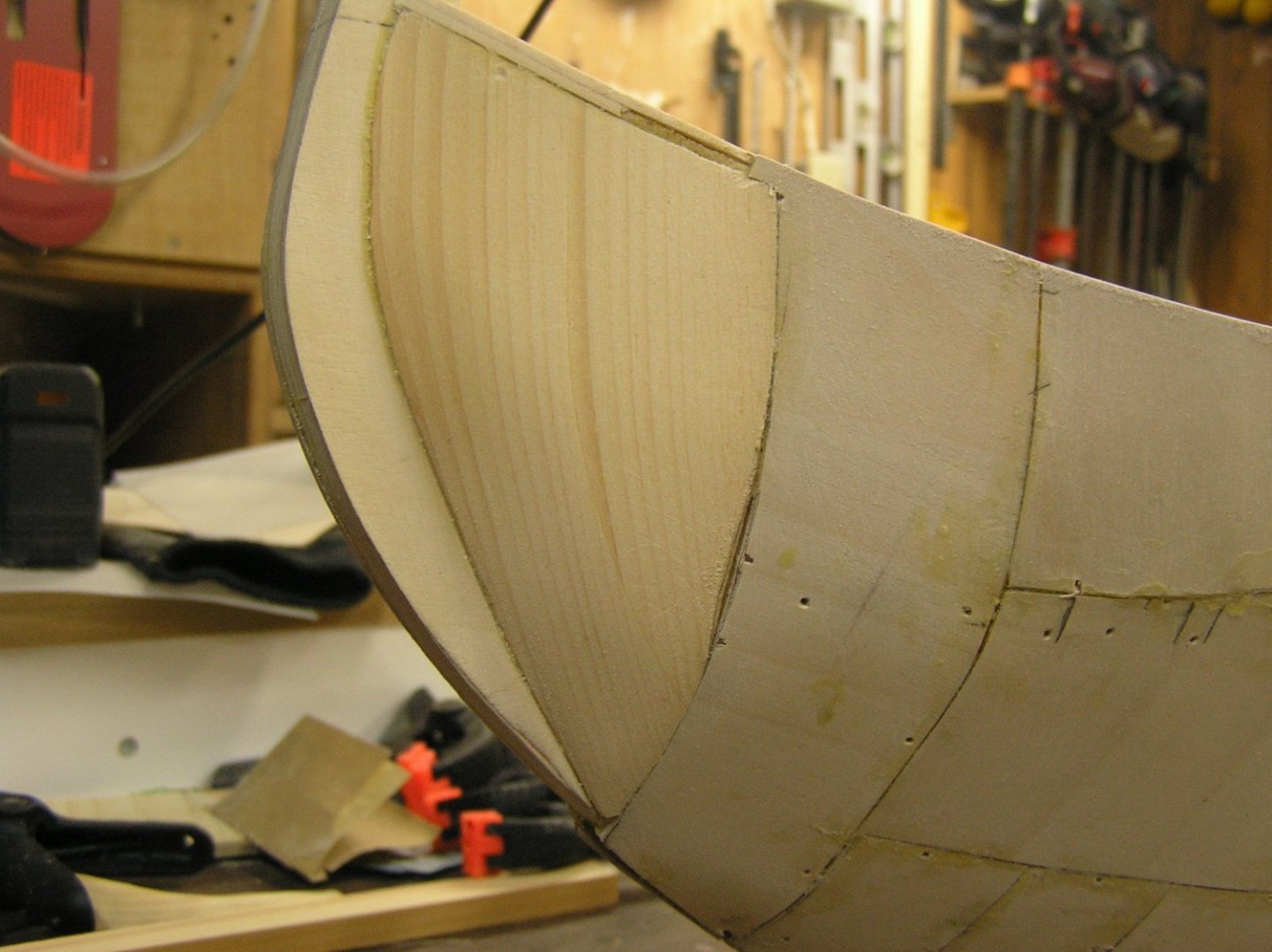
Have been working on the stern bulwarks. The starboard side is now skinned, except for some missing carved solid for the stem and ram. I used a solid piece of pine to shape the last couple of inches at the stern; couldn't imagine plywood bending to this recurved shape. Trimmed the starboard stern rail to width. Cap rail to come later. When I add the external keel, it will have to wrap partway up the stern and taper to get the sternpost projection right. Might be some trimming of the sternpost too. Obviously, there is going to be multiple filling/sanding cycles on this patchwork quilt hull. Now on to the port side stern.


- 536 replies
-
- 7
-
-

-
- Quadrireme
- radio
- (and 1 more)
-
Bill, Actually "grasshopper" is originally from "Kung Fu" starring David Carradine in the 70's. Loved that show as a teen. Maybe you didn't get it in the 'States....
- 1,508 replies
-
- 1
-
-
- Le Soleil Royal
- Heller
- (and 1 more)
-
Last spring we had a "derecho" (no I had never heard the term either) come through which split my neighbour's mature maple tree, half of which crashed onto and through our above ground pool. I'm still smarting from the paltry insurance settlement ("Was the pool more than 10 years old?" "Was the fence more than 10 years old?"). Tree crews were so swamped that I cut the darn tree up myself, with a swede saw, and lugged the parts to the street for pick-up. At least that was free. Bummer having no pool last summer. Debating a replacement, or new landscaping.
-
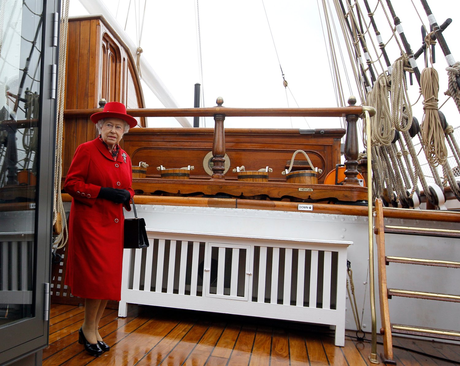
Vitus, it's many many years since I built this kit, but I do remember that the kit provided deadeyes are spaced a ridiculously long way apart, about 7 scale feet or so. It would be better not to take them as a model. Here's a pic aboard the ship. (God, that deck looks like a dance floor).

- 248 replies
-
- 1
-
-
- Cutty Sark
- Revell
- (and 2 more)