


Ian_Grant
-
Posts
2,156 -
Joined
-
Last visited
Content Type
Profiles
Forums
Gallery
Events
Everything posted by Ian_Grant
-
 Bill, regarding filling the hole in the knee of the head I would think that although filling after gluing these parts to the hull might be slightly awkward, it would otherwise be difficult to cut and glue in whatever you have in mind for the opening while maintaining the upper and lower parts of the stem in the correct position relative to each other. If your shaped fill was a little off, then the resulting one-piece "complete stem" might not then properly attach to the hull. In other words, you'd need a jig to hold the upper and lower parts of the stem in the correct orientation while you fit the filling. Might as well glue them onto the hull, then they are really and truly "jigged" for you. That's what I'd do.
- 1,508 replies
-
- 1
-

-
- Le Soleil Royal
- Heller
- (and 1 more)
-
For my Preussen's pedestals I used brass "insert knobs" from Lee Valley. They don't have a "bulbous" knob that you show. They're meant to accept a wood disc in the centre of the knob end that you provide but you can omit and just stand upside down. Smallest is 3/8" DIA, not sure how that compares to yours. https://www.leevalley.com/en-ca/shop/hardware/knobs/cabinet/40277-veritas-smooth-rimmed-brass-insert-knobs
-
Boy, Bill, you're not letting any grass grow under your feet.............!
-
Bob, yes your Transmitter is the TTX300 but what is your Receiver? Are you certain that the Transmitter has power? Do you have a volt meter? It would be worth checking the output of the ESC's BEC (battery eliminator circuit) to verify that the Rcvr is actually being powered. By the way, which ESC were you sent......7320....7325? Also, are you certain you are connecting the 7.2V batteries in series, not just y-harnessing in parallel, for your 12V motors? Again a voltmeter would be useful. You can buy a multimeter for as little as $17USD at your Home Depot. Lastly, I'd call Big Rich and have a helpful chat.
-
Bob, I looked at a video about binding your Tactic Transmitter to the Receiver. Is your Receiver a TR325? At any rate all he did was turn both on; should see a red LED on the Tx but nothing on the Rx. Then use a small screwdriver, for example, to press down on the recessed binding button within the Receiver and hold it down for about a full second until it beeps and a solid red LED comes on. Pretty simple; used to be you had to use a "binding plug" which temporarily plugged in to the Rx to indicate to it that you wanted it to attempt to bind. If no joy, check polarity of your three-pin ESC connection to the Rx: black or brown to the outside of the Rx. It's the ESC which supplies power to the Rx via this connection, and in return the Rx sends the speed control signal back through the signal wire. Looking forward to seeing your electrics run!
-
So I've seen several people who cut out those panels without damaging them, for re-use. Does it go quite easily?
-
Bill, I would think you'd need to have the beakhead and stern plates attached first to make sure the bulwarks are at the proper angle to fit. If you attach the bulwarks first you have no guide as to the tumblehome and then you could end up with a glued joint at the wrong angle. Just my opinion, as you know I've yet to start my SR. Later edit: Or, add the beakhead to have one fixed end, then glue the bulwarks with the stern plate dry fitted and clamped by rubber bands or whatever. My first recommendation above maybe you could end up with the stern plate at the wrong angle to mate with bulwarks. From playing with my kit pieces they all seem to fit together beautifully.
- 1,508 replies
-
- 1
-
-
- Le Soleil Royal
- Heller
- (and 1 more)
-
Bruce, the brown servo wire is the GND and goes nearest the outside edge of the Rcvr. The ESC should have either a black wire or a brown wire too; in either case this is the GND and again goes to the outside. Check these connections before trying again to bind. I don't know anything about Tactic components so can't help you there. By the way, the prop tubes should be solidly epoxied in. There should be no need for caulk, just grease in the stuffing boxes.
-
Just pulled out my instructions again; it appears that this deck level is where the gunport openings on the beakhead bulkhead are. The bulkhead is very tall on this ship.
-
Aren't there ports about there on the beakhead bulkhead? Or is that higher up?
-
Neat idea, Dick! It only took a few seconds of internet browsing to find that I cannot buy contour gauges large enough or with fingers long enough to follow my hull's curves. It would require multiple measurements from different angles which would be difficult to re-align on paper. Because of that I had decided to just slice 'em up. But your idea has my brain gears turning. Will have a think. Thanks for the post!
- 536 replies
-
- 2
-
-
- Quadrireme
- radio
- (and 1 more)
-
Normally props would turn opposite to each other. It's up to you to order a left hand and a right hand prop. Since a single ESC will be driving both motors, just swap the wires to one of them to get it to turn the opposite way. Modern ESC's switch their MOSFET transistors on and off at a rate somewhere in the kHz's. Sometimes in the audible range. I'd have thought a modern 2.4G Rcvr would be pretty immune, unlike the FM Rcvrs of my teenage RC years, but it is still a good idea to keep them separate. You should add small ceramic capacitors at the motor terminals to suppress the switching noise. I have not yet used modern batteries such as NiMH or LiPo; not sure can you just parallel your two to get more amp-hours? Or do you mean they are in series to give you 12V for the motors?
-
Seriously, it is a very nice kit of a totally impressive ship. As a bonus she had no cannons to rig. A good FUTURE project.
-
Yes, that's how to cut thin aluminum soffit; just turn the blade backwards and it gives a clean edge. And many many little aluminum slivers to pick up. Last time I did this I forgot to turn the blade back around when next using the saw. Couldn't understand why the wood seemed so hard.....😆
-
Yes, most servo connectors aren't keyed. If I'm not mistaken only Futaba connectors use keys. You can see the key slots on your Rcvr unit. All servo connectors plug into the Rcvr with the black GND wire toward the outside of the Rcvr. One needs to do a float test when all equipment is in. The boat is unlikely to float at waterline, or sit with a level pitch (bow to stern). Additional ballast will probably be needed, and is distributed give the proper pitch and depth. Your hull looks nice to me. For future info, I've read that brake fluid strips paint from plastic.
-
Bill is striving to complete his SR build so he can move on to a Heller Preussen kit. A kit which builds into another impressive model. Even though I paused mine, too chicken to do the ratlines.
- 1,508 replies
-
- 1
-

-
- Le Soleil Royal
- Heller
- (and 1 more)
-
Looking at Bill's pictures, and recalling my unused Heller Victory blocks, I wonder if those little stubbies sticking out of the sides were meant to prevent the strop thread from slipping off, if one passed the strop to left-right-left-right of the stubbies? I think one would be better just to file a notch at each end of each side no need to groove all the way along. Wonder if I will follow this advice if/when I get to my SR?
-
Marc raises an interesting point. On my version of the page Bill showed there is no indication of the fore-halliard knight; it seemed to just appear magically on my page 10 "Dressing the Decks" diagram. But on closer inspection there it is on my page 9 in the "Montage du Gaillard D-Avant" translated "Forward Quarter Deck Assembly". The fore-halliard knight is two parts #292 back-to-back. Bill don't forget to trap and glue the main halliard knighthead (258 & 259) as you glue the main deck parts 7 and 8 together!!!!!!!! This knighthead does not glue in afterward!!!!
- 1,508 replies
-
- 2
-
-
- Le Soleil Royal
- Heller
- (and 1 more)
-
Bill, according to my older printed instructions English translation for page 5, there are six "large knightheads" formed from pairs of part #162 glued back to back, and twenty-four "small knightheads" formed from pairs of part #163 glued back to back. These are scattered over the forecastle deck (9), the main deck (7 & 8), the quarterdeck (10), and the poop deck (11). The forecastle deck (9) gets two of the 162 just in front of the fore mast, and eight of the 163 along the bulwarks. The main deck gets four of the 163 knightheads two each side just behind the main mast. The quarterdeck (10) gets four of the 162 near the mizzen mast, three of the 163 knightheads along the starboard bulwark, and another three of the 163 near the mizzen mast. The poop deck (11) gets six of the 163 knightheads, two pair to port and one pair to starboard. In my instructions Heller has multiple dotted lines running to the various deck locations for these parts. It's sometimes hard to see what goes where exactly, particularly around the mizzen mast on the quarter deck. Later on (page 10 in my instructions) there is a large diagram showing the two boats floating above the decks of the ship assembly. This is labelled "Habillage des Ponts" translated "Dressing the Decks". This illustration includes all the various knightheads in place, and it is easier here to pick out the 162 "large" and 163 "small" ones. Note that a couple near the port bulwark are hidden from view in the drawing so don't let that confuse you.
- 1,508 replies
-
- 1
-
-
- Le Soleil Royal
- Heller
- (and 1 more)
-
In my teens I slapped a motor and rudder in a Canada Goose decoy for RC. The geese weren't fooled, no matter how slowly it approached them. 😄 At full speed there was a huge bow wave at its breast. 🤣
-
Or Lee Valley has these, intended for carvers. Don't really know if they would withstand a moving toothed blade; it might be bad news if a tooth hooks them. I saw a TV thing once where a married couple of marine film makers were feeding sharks **by hand** 😜 and wearing gloves like these. Somehow the lady's hand ended up stuck in a shark's mouth and the glove came off! She quickly stuck her other hand in and wrapped the bare one with it.........the husband kept on filming......thankfully it was all ok.........
- 536 replies
-
- 2
-
-
- Quadrireme
- radio
- (and 1 more)
-
Great project Dick! I look forward to watching your progress. You are right about there being very few records of these ships but it does leave lots of room for your own ideas. I've found the same regarding Roman war galleys; as you say, they only have old coins and pottery decoration, a handful of wall paintings unearthed in Pompeii, and a few relief carvings on for example Trajan's column for clues about these ships. And that's more recent than your project! Best Regards, Ian
-
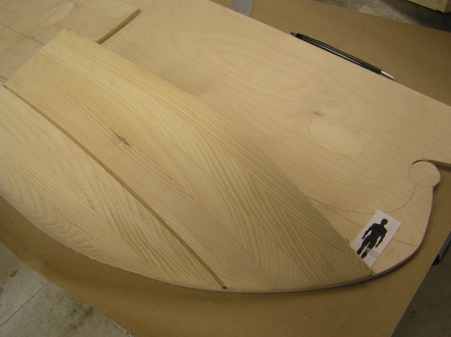
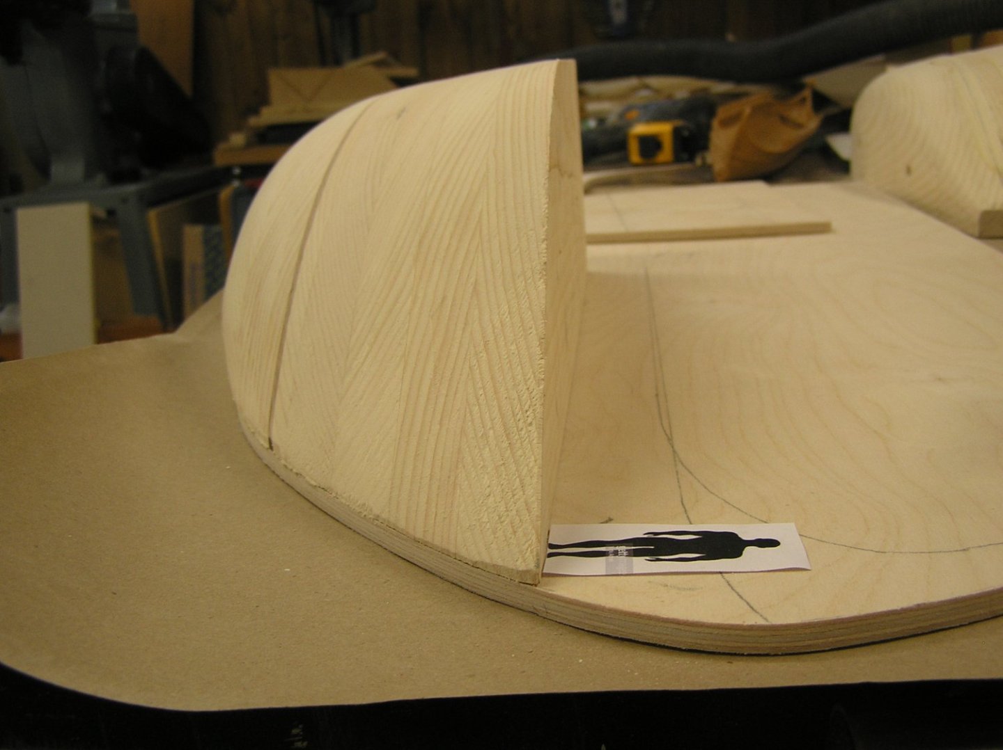
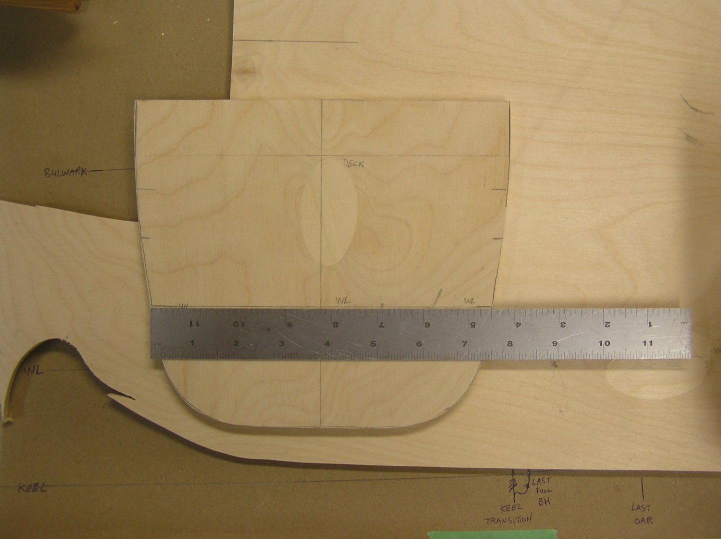
I made up a blank for the stern and carved it. This time I included a thin strip of cherry in the layers to mark the waterline. It was very painful to cut across all the end grain even with my low-angle block plane. Now that I have it I am re-thinking my plan to slice the two carvings up to get the sections; if I decide later I don't like the look then I am toasted. Maybe try a contour guage, which means buying one. Then I can always revisit planing the carvings if I want a change, and make new bulkheads...... Where Julius is standing this time is about deck level. The sternpost is not fully cut out of the ply, no commitments yet! Again, the upswept bulwark at the end is not represented. Third photo is my bulked up midships section to get the needed displacement - looks like an iron windjammer 😬.
- 536 replies
-
- 4
-
-
- Quadrireme
- radio
- (and 1 more)


