Ian_Grant
-
Posts
2,156 -
Joined
-
Last visited
Content Type
Profiles
Forums
Gallery
Events
Everything posted by Ian_Grant
-
 Bill; you should be! Nicely done!
 -
Doug, looking good so far! May I suggest that you add "RADIO" to your log title....this will attract the RC enthusiasts!
- 56 replies
-
- 1
-

-
- Colin Archer
- Radio
- (and 1 more)
-
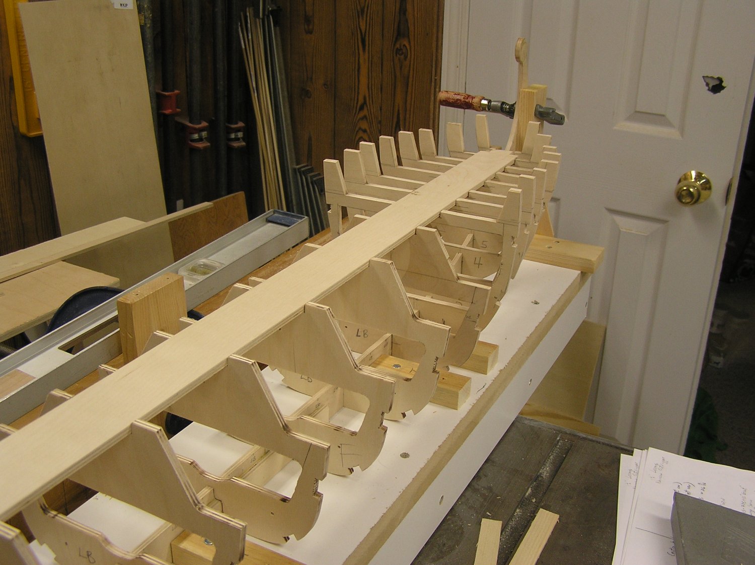
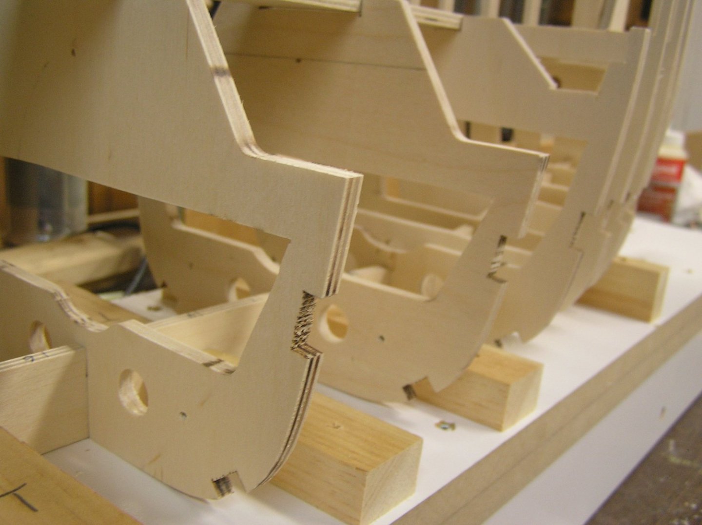
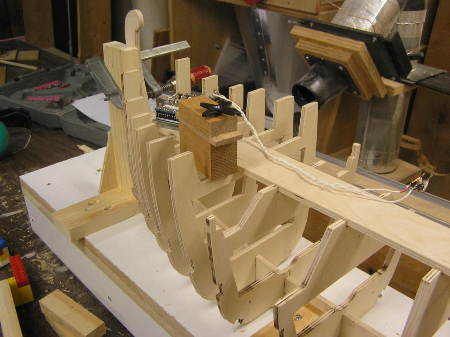
Finished hollowing out the bulkheads, and faired stanchions at the bow and stern thus allowing me to cut their inner faces at the appropriate angles and positions too. Almost ready to start glue-up! 😃 🤪 🤙 🤞 Drilled holes through bulkheads in the central portion partly to save some (paltry) weight but also for wire fore-aft routing safely out of the way of the moving parts. I sized the holes to pass Tamiya connectors on the main battery leads. Likely it will be amidships after all; I'd prefer to locate the sweep servos under the fore deck beside the arduino, as opposed to between the oar beams. On the other hand, the hump-pak version of the battery fits nicely under the fore peak, provided it's not too much weight too far forward. Will have to wait for ballast testing on the skinned and painted hull. Oh, also glued small pieces of 1/16" plywood each side of keel at the stem and stern, just to beef them up a bit. They were then routered to match the shapes. Looks better now to my eye. Bow view: I'll be cutting that "ram" rectangle off sometime; planning a flat face at the extreme stem with a dowel sticking out to attach a prefabricated ram. Likely 3D-printed. Stern view: Detail amidships:
- 536 replies
-
- 7
-
-

-
- Quadrireme
- radio
- (and 1 more)
-
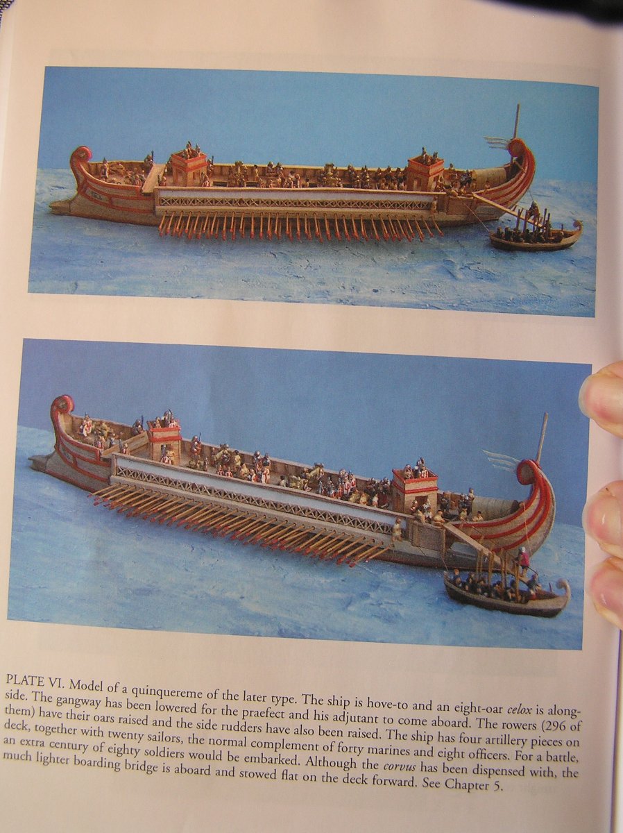
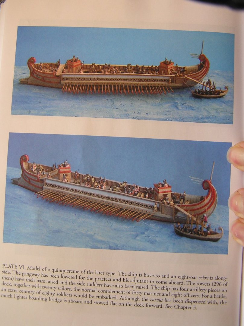
I don't think the outrigger is too short aft; behind it comes the platforms on which the rudders are mounted. Also they might have been used for boarding, as Pitassi depicts in one of his outstanding models:
-
Very nice so far, Bill! Happy New Year!
-
Eugene, looks great! What height did you settle on for the bulwarks? Maybe they mixed up Tennessee TN, and Toronto? Will you be carving the ram? I'm a long way from there, but for my large boat it would be cool to make one from brass and let it discolour with time. If I can't afford the weight I will TinkerCAD it and get my brother to 3D print it for me in plastic. I too was wondering about the deck. Last time I made an RC boat, in the 70's, I simply penciled lines on the deck plywood and spar varnished it. I want to do better this time. You found a cost-effective strip supplier in Europe? I think the outrigger extends a bit too far forward, if you don't mind the input. (Just let me know if I should 🤐!) 🙂 I'm going to a meeting of Rideau Nautical Modellers this Wednesday in Bells Corners. The guy told me I will fit right in with the members who use Arduinos, or who build electro-mechanical doo-dads. Don't know whether to take my galley skeleton, or the oar mechanism. Happy New Year!
-
But different inmates to stamp them out, I guess. 😁 When the Ontario Liberals got thrown out after too many years in power, the new conservative government decided to completely change the plate design. This cost quite a bit apparently, paying consultants for a new motto among other things. Fundamentally they switched from dark numerals on a white background to white numerals on dark, with other artistic flashes. Only after they started issuing them did someone notice that with the carefully selected new paint scheme, the numerals became illegible after dark under certain kinds of streetlights.....sheesh......😭...our tax money at work..... So they switched back again, at great expense.
-
About 20 years ago (memory is not exact) Ontario switched to "environmentally friendlier" paint for vehicle licence plates. Aluminum isn't the easiest surface; after a while they all started peeling. You'd see some plates with the entire paint layer free from the plate, only held in by those little frames some people buy, or you'd see plates with half the paint gone. At the beginning you had to argue to get a new plate without the replacement fee, then they brought in a 5-year "warranty" on the paint. Nowadays they still get some batches which peel, but they will replace for free. But you still have to go through the pain of waiting in line at the registry office to trade plates.
-
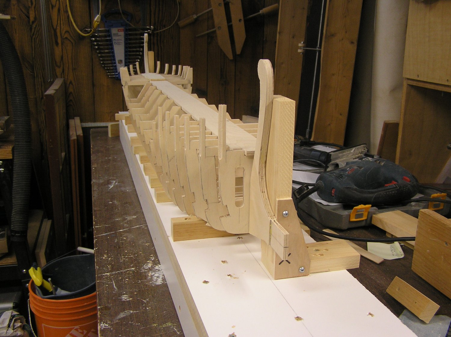
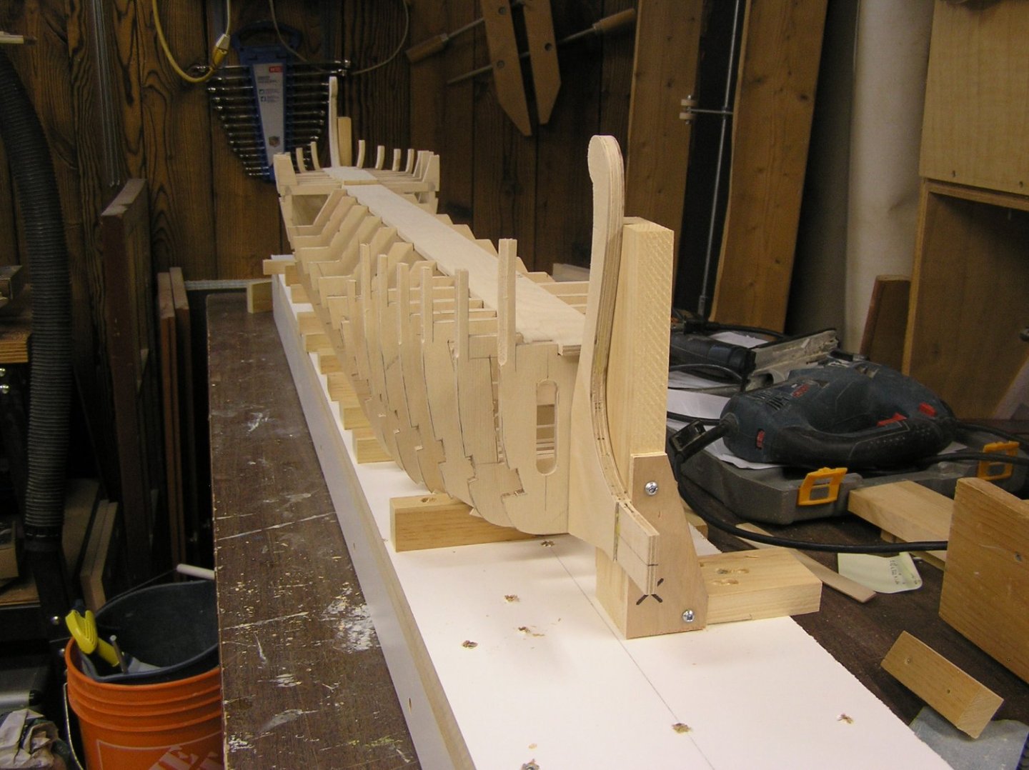
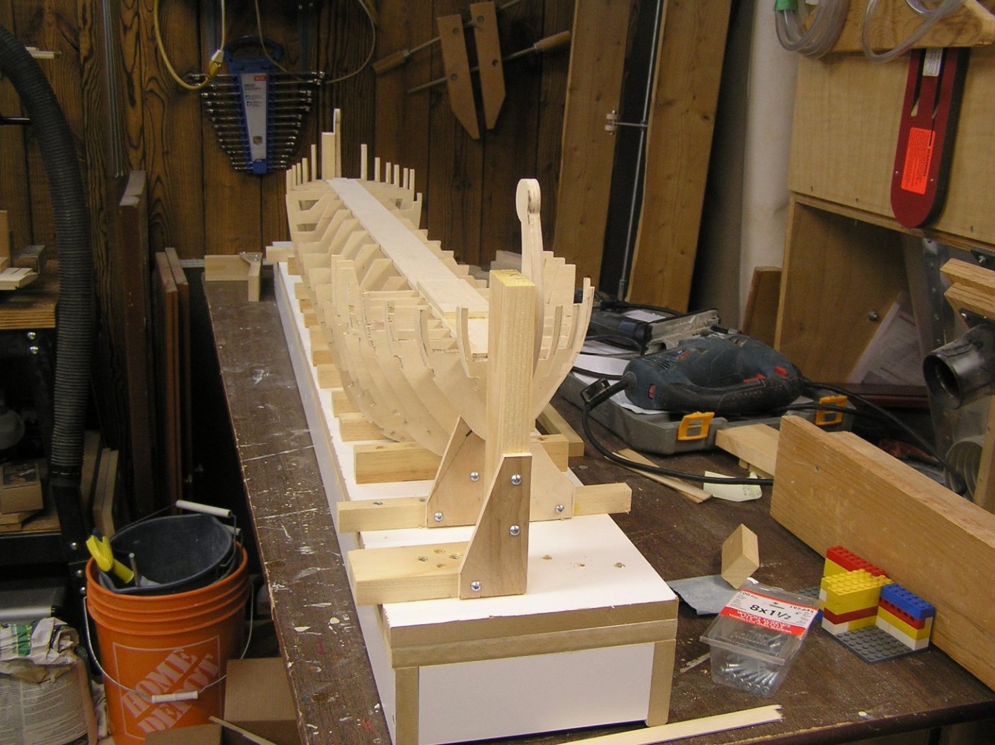
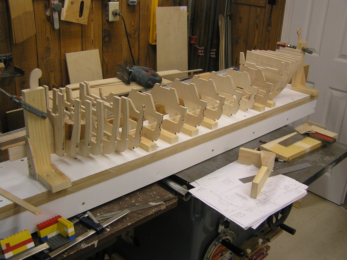
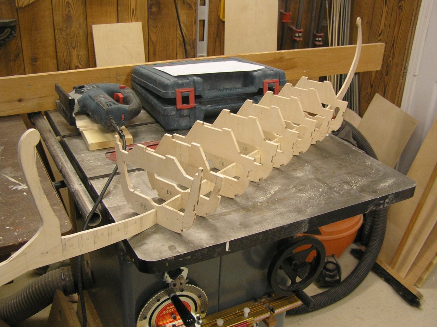
Made a strongback to assemble this thing straight and true. Working to finish the ribs. Hollowed out those at the bow and stern; still trying to decide on through-deck access. Thinking I will have the foredeck removable without the rest, just to access on/off switches. The boarding bridge can conceal the joint. The extreme forward deck will be fixed, back to the point at which the "artemon" (a sort of bowsprit) is fixed. Will be weighing the skeleton soon, just to see where I stand on the weight limit given the 4.2kg estimated limit for the wood hull in its entirety. Nothing glued yet, until I finalize the stringer notches. And cut the bulwark stanchions to width. I made slight alterations at the stern to eliminate the extreme "flare-out" at the bulwarks. I expect there will be problems as I just winged it. We'll see how fairing goes when I get there. That's the Arduino and a dummy sweep servo sitting on the foredeck. Happy new year to everyone!

- 536 replies
-
- 6
-
-
-
- Quadrireme
- radio
- (and 1 more)
-
Valeriy it's been a privilege watching you build this magnificent model! I wish you a Happy and safe New Year.
-
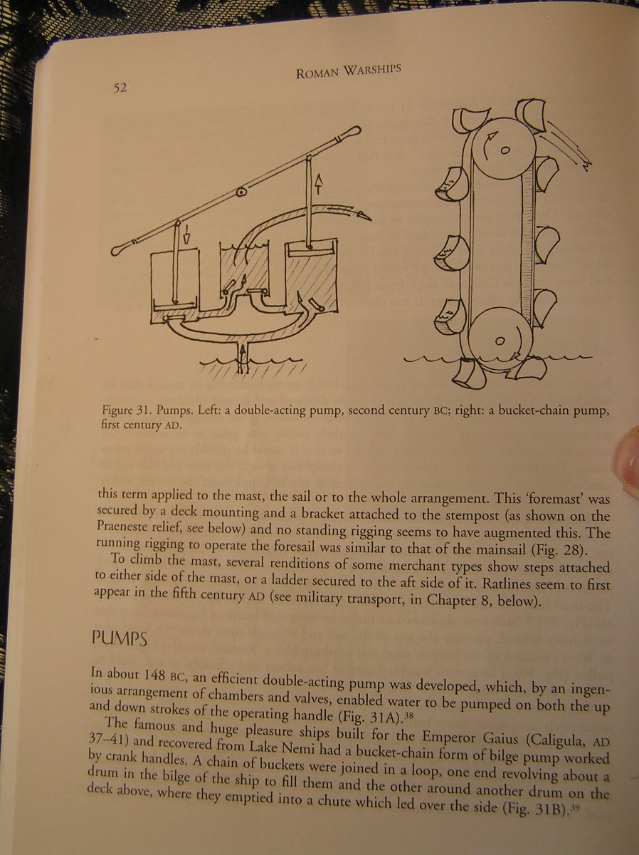
I debated the same thing about the bulwark. I'm aiming for about 40" after lying paper across "Julius" my 1/32 scale human figure cutout, but I'm not committed yet as my bulwarks aren't yet cut and anyway the top rail could vary a little. Bear in mind the average Roman male was 5'-6" or 5'-7" or so. Pitassi's drawings seem to show a bulwark even less then 3 ft; but that's trying to measure up from a drawing where the ship is only 4" long. That "Nave Roman" build seems to have pretty robust bulwarks. Pitassi does list pumps in his chapter on equipment, but doesn't mention Archimedes screws. Here is an extract from his book:

-
Wow! She's really beautiful!
-
I have used an old kettle and a length of PVC tube to steam wood for bending, but this was for a full-size canoe's laminated stems. It takes 30-45 min for 1/4" thick hardwood strips to become very pliable. The time required should scale according to thickness. I realize steaming may not be very practical for most modeling but I mention it here as it may be a way to do edge bending.
-
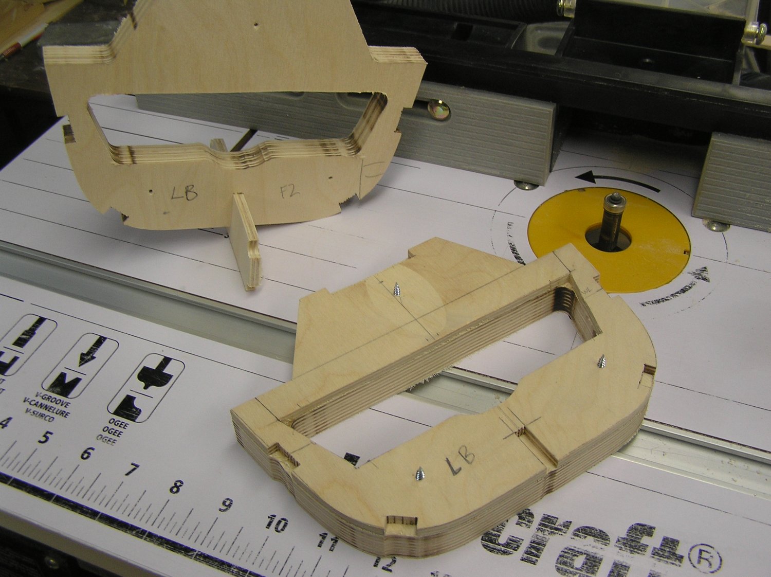
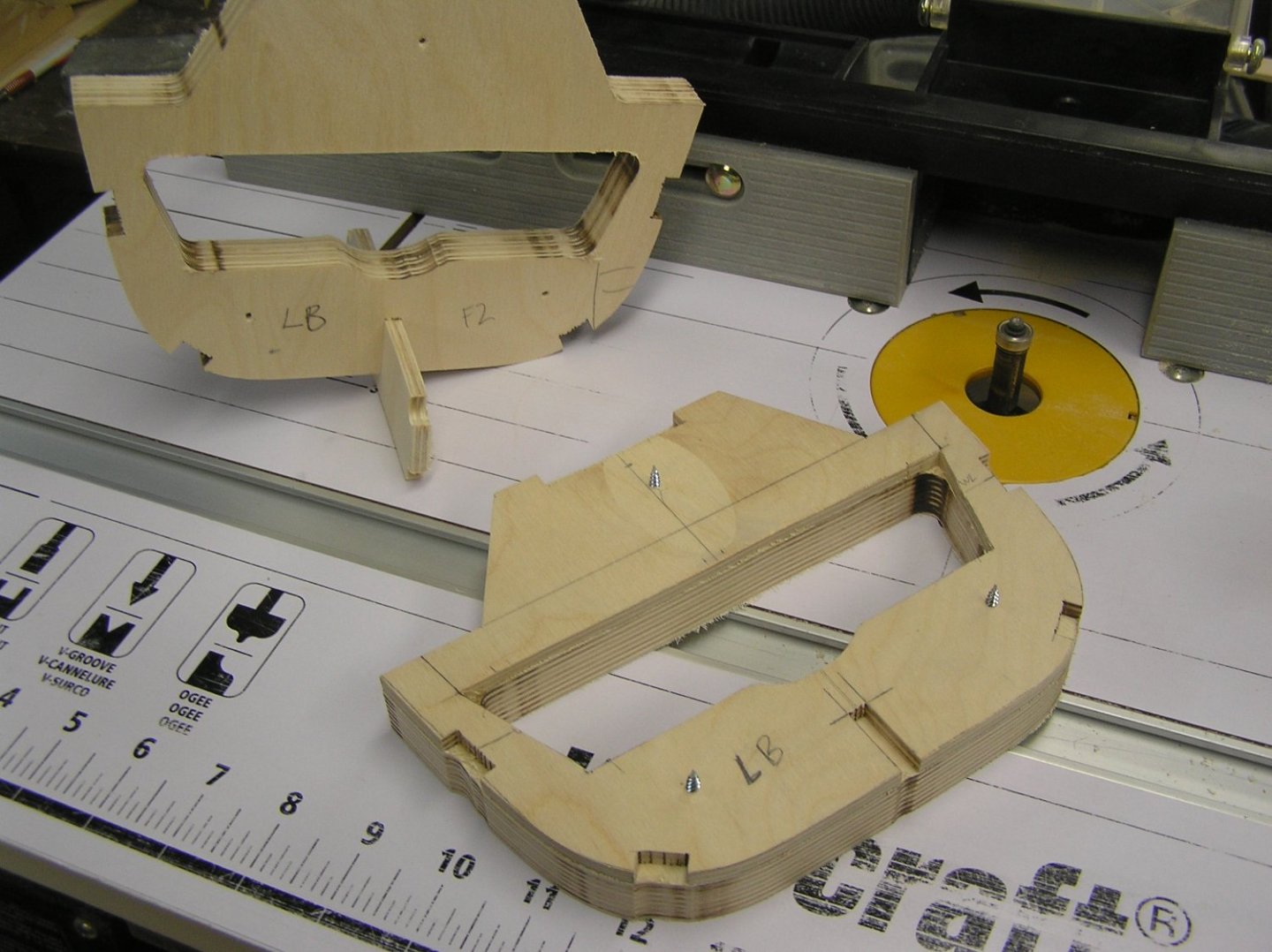
Bob is right - don't just grab some fir plywood from Home Depot. Baltic birch plywood has many all-birch plies, no voids, and full thickness outer plies, as opposed to face veneers, which are not so easily sanded through. I've just been gang-routering edges in 1/4" birch ply to form ribs for my current build. Edges are clean. This plywood is heavy and strong. I can barely break a 3/8" wide strip with full hand strength.
-
I wouldn't use hardboard, it's little more than compressed cardboard. Not suitable for a 9 ft model in my opinion. My choice would be 1/4" plywood. Maybe even 3/8" for the keel. Is this for display or on the water?
-
Nice looking bolts, Bill. And the anchor lining. I'm taking notes for my alleged future build. 😃
-
Bob, your decks look great!
-
Didn't Marc somehow melt the ends into more of a bolt head shape, I dimly recall? Or was it some other upgrade he made which involved heat?
- 1,508 replies
-
- 1
-
-
- Le Soleil Royal
- Heller
- (and 1 more)
-
Thanks Bob for this recommendation. CPES sounds ideal for my RC project; I was dreading the race to coat the inside before setting starts, and also trying to keep the coat thin and light.
-
Sorry, I thought you had seen my log as there was recent mention of a bandsaw in it.
-
I take it you looked at my log. 😄 I'd love to have a big shop, mine in the basement is about 15ft x 16ft. If my dad could see the mess in it right now he'd have a fit. I debated doing an RC galley or a square rigger; I thought the galley would be an engineering challenge but tedious to sail after a while, while a square rigger would be easier to build (many plans available) but a constant challenge to sail (multiple sail winch servos). For better or worse I opted for the galley this time but I would still like to do a full rigger if not a 4-masted barque. I have the catalogue of Harold Underhill's sailing ship plans. Happy modeling!
-
Fantastic display Glen! She looks great! Just worried about that stick holding the lid open....😉
- 134 replies
-
- 3
-
-
- Captain Kidd
- bottle
- (and 3 more)
-
I've used West System to build a cedar strip canoe and repair my fiberglass dinghy. I love the stuff and the results. The resin is a constant but you can buy hardeners with various cure times, and also cellulose filler to thicken it up. I've never thinned it; the reason I mentioned it is I've seen several mentions in RC forums of painting the inside of a hull with "thinned epoxy" hence my question. I will need to waterproof my current RC build (first in 40 years), when I get to that point, and I thought "thinning" might reduce the coating's thickness and hence added weight, which is a concern. Here is what West System has to say about thinning their epoxy: https://www.westsystem.com.au/wp-content/uploads/2019/07/thinning_epoxy.pdf
-
Having said that, I don't know what to thin epoxy resin with. 😄 Could you clue me in? Thanks.
-
The custom for RC is to use thinned epoxy resin on the inside. You'll need to fiberglass planking on the outside with light cloth and resin.