


Ian_Grant
-
Posts
1,667 -
Joined
-
Last visited
Content Type
Profiles
Forums
Gallery
Events
Posts posted by Ian_Grant
-
-
I found some time to hook it all up. It all seems to be working as expected. Features like the inside oars on a turn stopping, then back-stroking if the rudder goes really hard over, are shown in the following video.
After my son shot the above video, I realized I forgot to show the "pause" function I programmed in. This "pause" is a momentary stop in the oar motion at the end of the power stroke. The duration in terms of RC cycles (20 msec) is entered at the start of the program. I have entered 12 for now, representing 12 x 20 = 240 msec, approx 1/4 sec.
-
Bill, I continue to be amazed at your speed. One note, though, those brass "whiskers" across the taller cranes near the top are meant to be removed.
Regards, Ian
-
When I was doing that, the mizzen was so small inside I used a bicycle spoke. Not a great idea when it came time to drill a hole for a pin to hold the cro'jack yard, LOL....
-
-
Wonderful looking cannons! And those engravings!.....
I'm currently working on the Heller Preussen so I have no need of cannons just now, or indeed for a year or two, but I have in my stash the Heller Soleil Royale in which the cannon barrels are nicely detailed but rather too small in diameter. You might be able to sell quite a few of an improved version to builders of this, I won't say popular, but well known kit.
Regards,
Ian
- thibaultron and mtaylor
-
 2
2
-
-
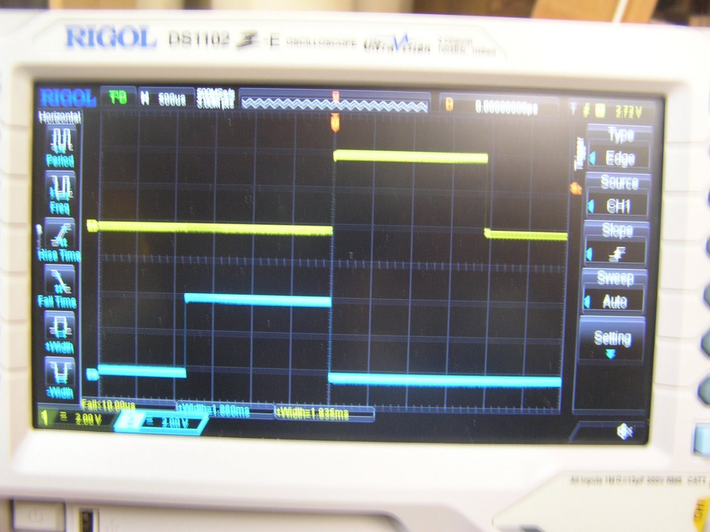
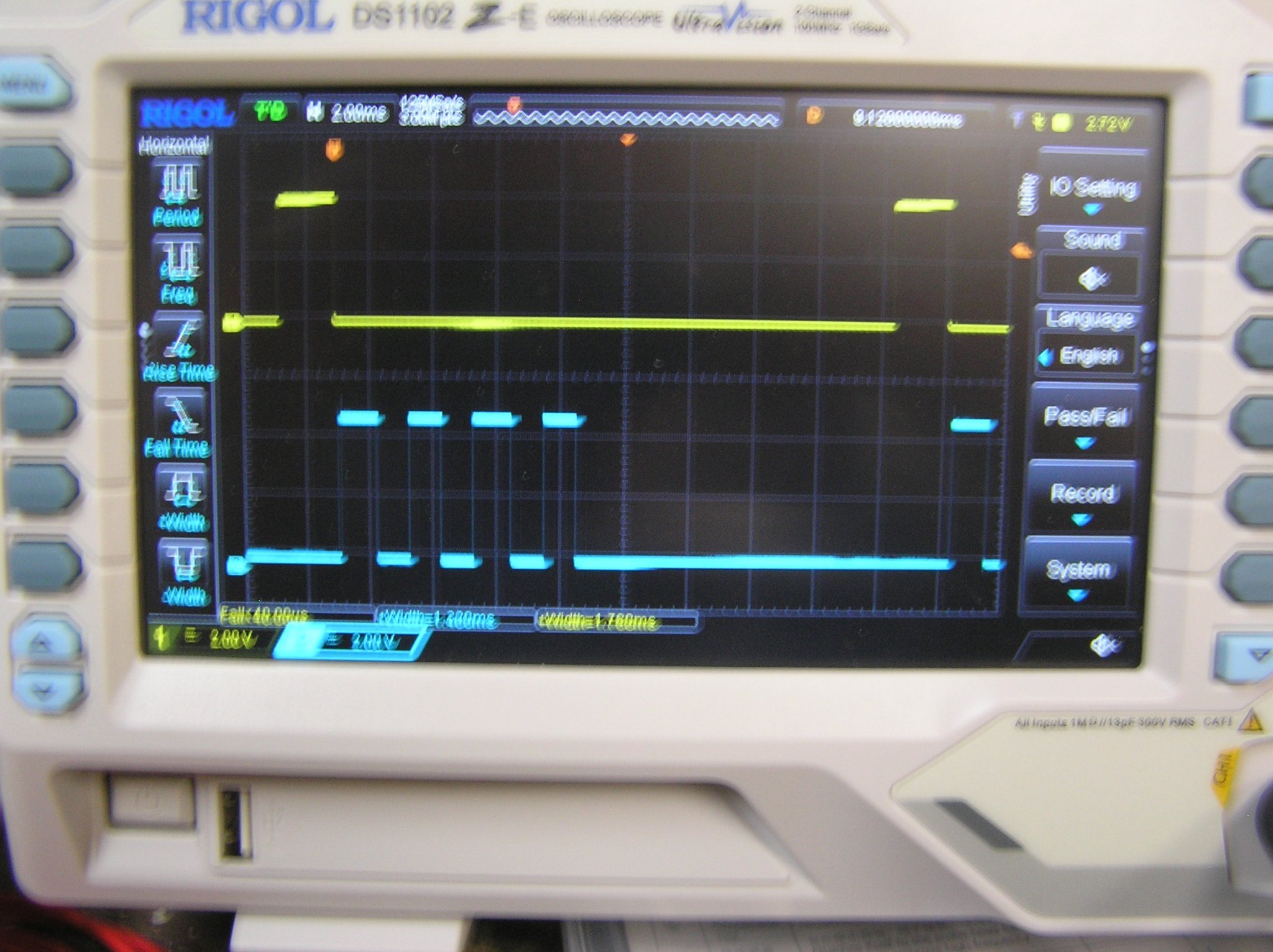
Well, I think the program is working at least it looks that way 😁. I didn't dare plug servos into the daughter board on the first try in case the software generated invalid pulse widths which could perhaps damage a servo by trying to make its motor go beyond the mechanical end point, however I used my new 'scope to observe the output pulses. Yes I did get a 'scope and it is the only way I got to where I am in debugging. It is a joy to have for stuff like this.
Here are a couple of shots of the "throttle" and "rudder" pulses from the RC receiver into the Arduino. There were two things I did not expect, (1) the trailing edge of one always exactly aligns with the leading edge of the other, and (2) the "rudder" pulse from the right stick on the transmitter comes first; somehow I assumed the signal from the left stick would be "channel 1". These two shots show them both at 1msec minimum, and both at 2msec maximum. Actually they don't quite get to 1 and 2 msec without moving the transmitter's "trim" adjustment sliding pots.

After quite a lot of effort to read these pulse widths and derive appropriate pulse widths to output to the servos, I decided to rewrite the code, abandoning the Arduino "servo library" completely for technical reasons. The most important was that the moment I defined an output pin as going to a servo the Arduino started generating a pulse stream at the pin, with interval 20msec as defined by its own internal clock divider. Of course, there is zero chance that this matches the 20msec interval defined by the RC set's crystal so the output became asynchronous to the inputs which led to issues I won't detail here. I wanted to keep program flow simple: measure the two input pulses; calculate next positions for the four oar servos; send out four appropriate servo pulses; sit in an "idle" loop while waiting for the next input pulses. Nice and synchronous and easy to monitor on the scope. Since the period for RC sets is 20msec, and the two input pulses are each 2msec at most, I have 16 msec for the calculation and sending of four pulses. The four pulses take at most 8msec so there is plenty of time for each program execution cycle.
Instead of using the "pulseIn" command from the servo library I rewired the two connections from the RC Receiver to the two Uno pins which support external interrupts. The program configures them to interrupt on either rising or falling edges at these pins. The interrupt routines read the DC level at the pin (to know whether the interrupt was because of a rising or falling edge) then record the internal clock counter reading in either a "startTime" or "endTime" register as appropriate. If it is the end of the pulse, a flag is set before returning to the main program. The main program sees the flag then knows it can calculate the latest pulse width by subtracting startTime from endTime. It then resets the flag and continues.
To send a calculated output pulse to a servo, the code simply sets the output high, waits the calculated time using the "delayMicroseconds" command, then pulls it low again; no interrupts required.
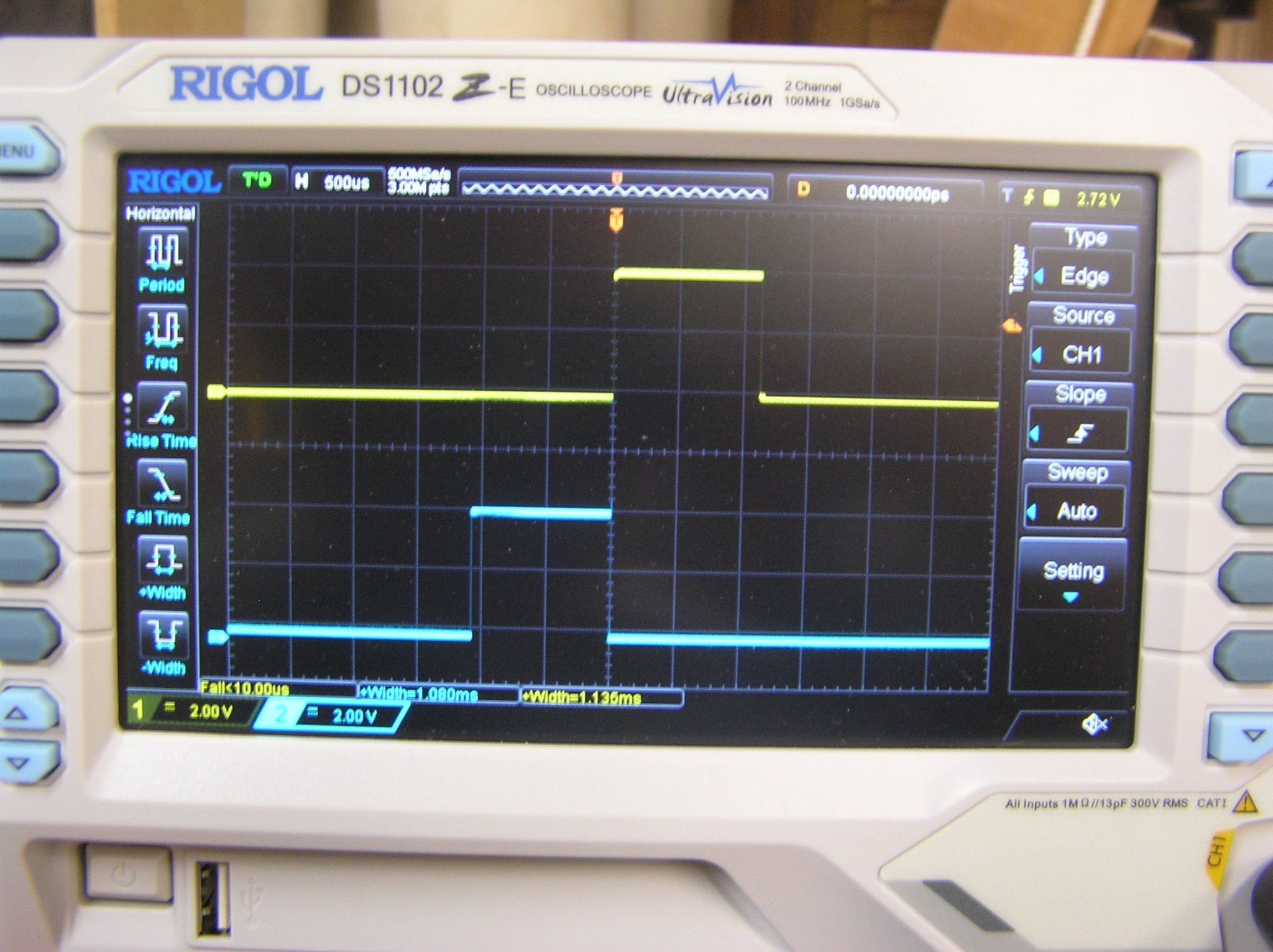
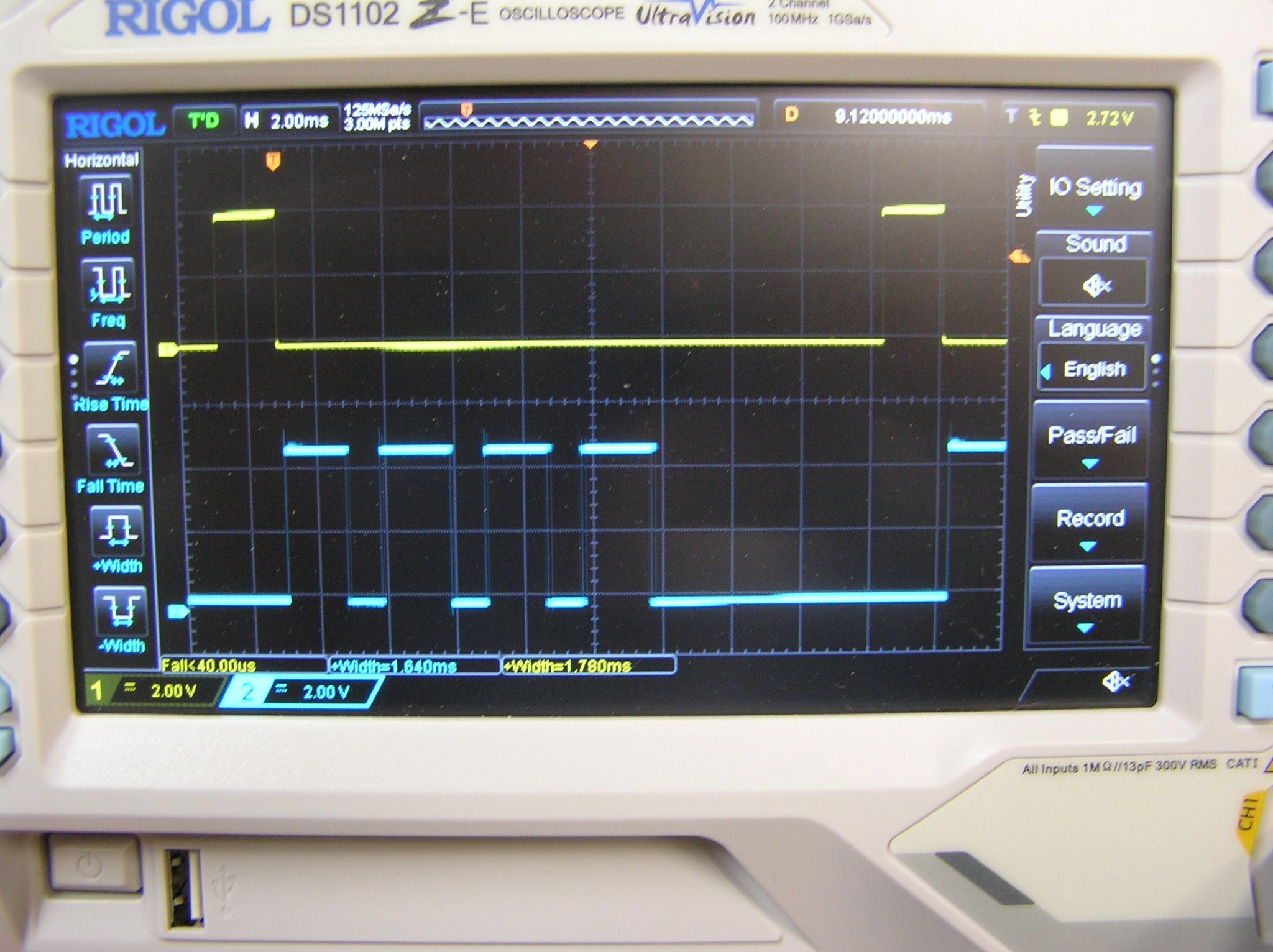
To spare the servos potential damage, I sent their calculated pulses, one at a time with 1 msec pauses between, to a microcontroller output pin to which I connected a scope probe. Just as well because the the first try did not go well and sent pulses much much wider than the servos could have handled safely. After some debugging effort I got correct-looking pulses. Here are a couple of photos.


The top trace is the incoming throttle pulse, repeating at "20msec" intervals. The bottom trace shows the four pulses which would go to the oar servos, completely synchronous to the input. You can't see it from these static photos but the pulse widths for the two sweep servos "breathe", getting wider then shrinking again to make the servos move the oars back and forth (observe the difference in the pictures). As I advance throttle they vary more and more quickly, indicating the oars are moving faster, as expected. If I put the rudder to one side, I can see the inboard oars stop moving as designed. If I jam the rudder hard over I can see the relationship between the "sweep" and "lift" servo on the inside of the turn "flip" as that side begins to backstroke.
The time from the falling edge of the throttle pulse to the first output pulse, about 0.2 msec, is the time taken by the program to record the throttle pulse's width then calculate next positions for the four servos for this RC cycle.
I didn't have time to try it on the actual rowing jig 'cause I was setting up all my Hallowe'en display this afternoon but hopefully I can try it tomorrow. I also plan to add code to make the stroke elliptical, which only requires changing the formulas in four lines of code. In fact I can use the daughter board's DIP switches to select between rectangular and elliptical motion just for fun. I'm pretty excited and looking forward to seeing oars move.😀😜
-
Wow, very nice catheads Daniel! And I love all the crew members on your gun decks. You should consider doing a cutaway on one side (or maybe get Kevin to make a part-hull side in clear resin? 😉) to show your outstanding detail.
-
On 10/30/2021 at 10:39 AM, rookie said:
Hey Ian
Just went through this topic; very cool!
Thanks for the link
Glad you didn't ask me for "help" with coding 😀
C++ not really my thing
Looking forward to seeing it afloat ...
Hey bro! Well C++ or programming in general is definitely not my thing! C++ seems to have more punctuation than anything else. I've run into situations where I make a syntax error in a program statement but the compiler doesn't complain and the statement just does nothing when executed. Not sure why the silence from the compiler.
However I did borrow a great book from the library "Teach Yourself Arduino Programming in 24 Hours" by Richard Blum. I highly recommend it to anyone starting with arduino.
-
-
Yes, #340 is the "marines' walk".
She is looking good!
-
Bill, your photo of the "next mess" reminds me: to forewarn you, the marine's walk has some slots among its grid surface for the mainstay and main preventer stay collars to pass through it. Their locations are wrong, given that these stays pass to the right of the foremast (which is why there are no boarding pikes on that side of the mast) and are not centred. If you use Heller's slots you'll have a kink in these high tension lines. Blue Ensign had a detailed description of this on the, all together now, "old Pete Coleman Victory site".
Don't glue the walk in until you have tested the alignment to the mainmast and shifted the slots.
Also I seem to recall some difficulty getting part 358 installed around the necessarily previously installed bowsprit gammoning (see Longridge pg 225) but the details are foggy. I forget the sequence I used. Try some dry assemblies to prevent getting into a corner. 🙂
Did you happen to buy Daniel's resin knighthead? Whether or no, it is best to attach the relevant blocks to the front of the knightheads now because access is more difficult after this assembly stage is completed. See Longridge pg 266 Plan 10 for list of purchases which use these blocks.
-
Nice buckets!
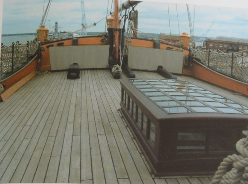
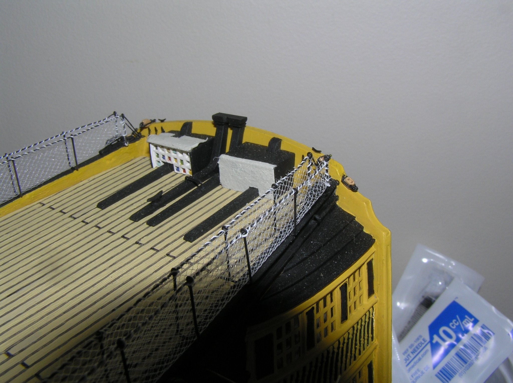
Those boxes at the taffrail are the flag lockers, which are just a bunch of cubby holes with a canvas flap over the front face, not a wooden hinged lid on top. The blobs of styrene supplied by Heller are unappealing. I copied Blue Ensign on the old Pete Coleman site, and cut the front off one, filling it with an array of short lengths of square brass tubing. I put coloured bits of toothpicks in to simulate folded signal flags. The canvas flaps were simulated with thin bandage tape, one being open to show the flags.
Here is a shot from the build. The real locker has many more cubbies, but I called it a day at this point.

I could only find this shot of the real thing:
- Hubac's Historian and dafi
-
2
-
Hi Richard! I'm glad you found this, and may I say I'm a great admirer of your gorgeous triere! Of course I had seen your smooth mechanism before but I wanted to try something different.
By the way, I wonder why I get no notifications if someone comments in this log that I started?
Update: I've been testing code, overcoming newbie arduino problems and getting used to it. At one point I was stuck for hours trying to get a bunch of nested IF's to do what I wanted! 🤪 I finally got around it by rewriting code to avoid such deep nesting. I just completed writing the program last night but only the first third is tested. As now written, the oar motion will simply be rectangular because I wanted to try to get the jig's oars going to be able to test the turning features etc. I can easily refine the stroke shape later. I wrote the code to stop the inside oars in a middling turn, and reverse them on a hard turn, whether going forward or backward. Should be interesting. Also, as written, as throttle advances there is an initial range over which the strike rate (oar cycles per minute) is constant but the sweep length gradually increases to full, then a new range over which sweep length stays at full but strike rate increases, to max speed (which would be short duration for actual human rowers). It also occurred to me while walking the dog this morning that there's no reason for the oars to move at the same speed on the power and return strokes; I will try speeding them up a bit on the return stroke to see how it looks.
Software provides flexibility, but it also means there are a thousand possible ways to do this. I'd need an actual model to finalize the parameters eg how effective is the rudder for slight course corrections without changing the oar motion, when exactly to reverse oars on a turn, what's a good strike rate for the slower speeds, what's a reasonable strike rate at full speed, etc.
Rainy weekend coming up so I will try debugging. Another video to come soon I hope.
-
Doh! We spent our summer camping trip on Superior west of the Soo within sight of Whitefish point but I never heard of this museum. Oh well the border was closed anyway. Next time for sure!
- thibaultron, mtaylor and JKC27
-
3
-
-
-
-
Like many builders I paid zero attention to Heller's rigging instructions; they might as well be in Etruscan.
I recommend you do the same.
I read through Longridge's rigging instructions many times - evenings, at hockey and ringette practices, weekend afternoons. It's actually a pretty short read, given all the other info on hull building etc in this large book. I agree that Revell's rigging instructions are to die for, for sequence of events. Use them as a general guide for sequence, and look up lines in Longridge to get the details.
Like I said before, I actually rigged jeers etc before any standing rigging (apart from looping shrouds over the masthead), for reasons of access.
While reading Longridge through, I made notes in a Hilroy exercise book regarding extra eyebolts required etc.
Plan, plan, plan! 😀😃
-
Two years in a rented room to rig her, even in Detroit, would be prohibitively expensive 😁.
Just want to add that my maintop photo was during build, hence the few slack lines and dangling ends 🙄.
-
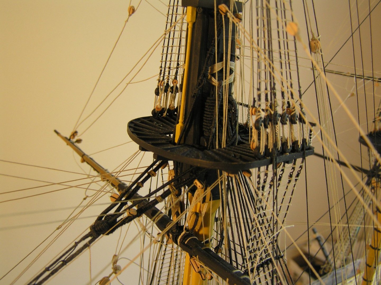
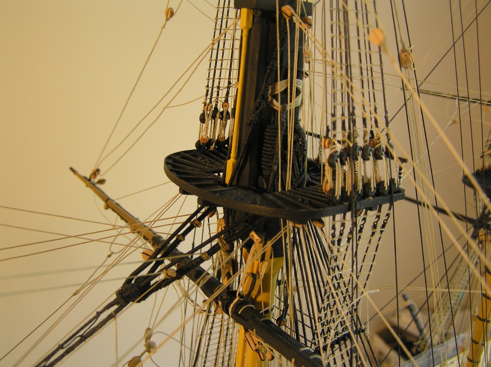
Hi Bill; That's how the topgallant shrouds (not the backstay) tie off, in the mast tops - the deadeye shown is one of the topmast shroud deadeyes with the short iron plate to which the futtock shrouds hook.
This photo shows my model's maintop. The thimbles inboard of the shroud deadeyes and lanyards can be seen, as can the black topgallant mast shrouds rising inside the ratlines. Also you can just see the hooks on the futtock shrouds below the top.
- dafi, mtdoramike and Hubac's Historian
-
2
-
 1
1
-
I think I rigged it from masthead to eyebolt figuring at least it's outside the hull. Either way works.
-
Rob, did you make those pump crank wheels?
-
Bill,
Consult Longridge pg 233 first paragraph, and last two paragraphs.
In summary, the two deadeyes on the stool are for the topmast standing backstay, and the topgallant backstay.
The royal backstay either has a thimble on the end lashed to an eyebolt on the stool, or lashed to a 2nd thimble attached to the eyebolt on the stool. This eyebolt lives behind the topgallant backstay deadeye which is why you can't see a 3rd attachment in the big drawing. This backstay is Heller's "1032"; I guess they want you to attach the thread before it is inaccessible behind the deadeye after you add it.


Roman Quadrireme Galley by Ian_Grant - 1/32 Scale - RADIO
in - Subjects built Up to and including 1500 AD
Posted · Edited by Ian_Grant
Thanks! After viewing the video I checked the "elliptical" calculation again since I didn't see much difference even though I said so in my ad lib narration. The equations are correct; not sure why the change isn't more obvious.
The noise is still an issue, although the "juddering" and "thud" you hear when the oar beams are going down would go away in the real ship in which I would use stainless steel upright shafts and linear bearings. Not two pieces of wood with a dado in them 😁.
Yes, I thought of having the arduino generate, or maybe just trigger an external circuit, to generate a bass drum beat, but apparently they actually employed flutes to time the rhythm not drums which are a Hollywood thing. Treble sounds from flutes are more easily heard then a bass sound in a ship with all its timbers and oars groaning. And maybe the oarsmen too?