


Ian_Grant
-
Posts
1,667 -
Joined
-
Last visited
Content Type
Profiles
Forums
Gallery
Events
Posts posted by Ian_Grant
-
-
She's looking great, Bill!! You continue to impress with your blinding speed 😄.
Foremast should be vertical; mainmast raked slightly aft; mizzen raked aft a little more.
Yes the beakhead bulkhead fits over the end of the forecastle deck.
Next thing for you to read up on in Longridge are the truss pendants for the lower yards. To rig these you'll need to add some eyebolts around the bases of the masts. Welcome to the serious rigging phase; and for this model it is very serious.
-
Estimate but be generous; as in woodworking you can always cut a plank (or a thread) shorter but you can't cut it longer.....
-
On 9/15/2021 at 1:13 PM, Ian_Grant said:
Longridge also has a photo, Plate 46 between pg196 and pg197, showing the bitts. The aft bitts receive the jeers and garnets, the forward the topsail sheets, as the caption mentions.
Note: on the old Victory web site there was debate about whether a larger gap should be opened in the gratings to allow these lines to pass through, or whether the gratings should be removed entirely. Not sure there was a firm conclusion; Daniel might have an update 🙂.
See Plate 46
-
On 9/16/2021 at 9:55 PM, mtaylor said:
"Jitter" as I recall can be caused by several things. One is the charge time on any caps in the circuit or also the choice of processor. There doesn't appear to be any shielding or decoupling methods here. Depending the frequency this operates at you could be picking up a lot of circuit noise. Might be that motor controller is what you need as that's what this circuit is doing. Do you have any "friends" that have a TV repair shop? Or are HAMS? I"m thinking for a o'scope.
Lastly, double check (use magnification and check all your solder joins. You could have a solder hair crossing terminations which is something I did more than few times back in the day.
No luck so far on finding a scope. The PWM pulse widths from the Rcvr, as reported by the Arduino, vary by about 20 usec so yes maybe that's the effect of noise but that would be a lot of noise on the edges. On the other hand this is an old 75 MHz crystal set, not a modern 2.4 GHz one. I changed the program to keep a running average of 5 readings and the variation reduced to 1 usec.
That said, I decided to see how steady servo movement would be with the Arduino driving it with a repeating pattern while ignoring the Rcvr pulses, wondering if I would see a jittery response. Short answer is that the servo movement is rock solid. I noticed no jitter whatsoever.
I also realized that in the final program, once per RC 50Hz cycle, the code would calculate the next settings for the four oar servos, then send out their respective PWM pulses one after the other. This means that the start time of a given pulse depends on the duration(s) of all pulses sent before it, e.g. if I send out 1msec, 1msec, 1msec, 1msec ... and in the next cycle 2msec, 2msec, 2msec, 1msec, ....then the fourth channel will see a delay of 23 msec between the start of its 1st and 2nd pulses since there are 3 extra msec to wait for the first three signals the second time around.....we're straying a ways from model ships here but I find it interesting 😁. This worried me so I wrote some code to slowly switch a servo between two positions, but with different inter-pulse delays. I saw no ill effects at all. Apparently servos aren't too concerned with the actual pulse repetition rate, just with the pulse width. Great to know.
-
Bill, I refer you to my post #461 of this log.
The note I refer to is shown in your photo of pg 267, at the top right of the diagram. It is best to tie the ends of these threads to the bitts (parts #89) before adding the 1/4 deck.
You'll need to allow enough length for each, given their runs as described below:
The mainyard jeers run up the mast to the upper jeer blocks beneath the mast top, reeve through the jeer blocks until all their sheaves are filled, then are timber hitched to the yard. See PLAN no. 8 (yes it's the foreyard but the jeers are the same).
The topsail sheets run up to the large quarter blocks slung under the mainyard, then out along back of the yard to the topsail sheet blocks, then either to the clew of the topsail (if you rig with sails) or the clewline block (if no sails; you can see in Plan 7 the topsail sheets ending at the clewline block for the topsails).
The mainsail clew garnets run up to the upper clewline blocks on the mainyard (just outside the octagonal part), down to the lower clewline block at the clew of the mainsail (if rigged) or to the lowerclewline block in mid-air below the mainyard (no sail; see Plan 7 which shows the dangling clusters of clewline/sheet/tack blocks below the for and main yards), then back up and tie off to the mainyard just outside of the upper clewline block.
-
They look fine. I would move on too. However I just noticed in your photos that some ringbolts are missing: there should be one in the deck behind each cannon, near the hatch coamings. This is for the "steady tackle" to an eye in the rear of the carriage which they rig to stabilize the guns in heavy weather. You see a couple of them in Longridge Plate 17, and on his model Plate 50.
-
-
Bill, sorry to say but I think the thread might be a little oversize. Longridge doesn't mention tackle or breeching rope sizes and I don't recall what the old Victory forum consensus was, but check out this photo from Victory:

-
I came across this article while searching (in vain, again) for Roman galley plans. It's a few years ago but I thought it would be of interest.
https://www.nytimes.com/2016/11/12/science/shipwrecks-black-sea-archaeology.html
-
Some progress, of sorts.
I can now read the width of the PWM pulses from both channels of my RC Rcvr using the Arduino. Program flow is: Measure Ch1 input pulse width, serial write to monitor, measure Ch2 input pulse width, serial write to monitor in a second column. Snag is that it doesn't work reliably unless I insert "wait" delays of 4 or 5 msec after each serial write. Not sure why; something to do with latency on serial port?? This also means that I am not reading all pulses; the 5 msec wait time after Ch1 eclipses the input pulse from Ch2 so the Ch2 pulse I actually read after the delay is from the next RC 50 Hz cycle. Not really important in the scheme of things since it's only a 20 msec relative delay.
Then I wrote another little program to read CH1 input and send the pulse to a servo connected to one of the Arduino outputs. It works! I can control the servo from my RC transmitter's stick even with the Arduino interposed between the Rcvr and the servo! Cool! Snag is that there is some jitter on the servo. I realized that this is due to fluctuations in the pulse width readings which may be due to noise. Another reason to need a scope for this project. I could send the servo a running average to smooth it out but in an actual model I was going to read the sticks just at the start of each rowing cycle so it might be ok.
Next test will be to drive a servo slowly back and forth, ignoring the RC rcvr, to see if that can be done without jitter.
-
11 hours ago, Kevin-the-lubber said:
They do look too big, don't they. I've printed off some scaled down blocks at 1.5mm and 2mm as per Ian's excel sheet and these are incredibly small; this looks like ......<snip>
My spreadsheet has all the exact block sizes calculated in a row near the bottom; somewhere just below that is a line indicating which available scale block size to use. A given scale block size necessarily covers a range of actual sizes. All this to say that I used 2mm to cover the smaliest blocks. I wouldn't advocate trying to find or fabricate 1.5mm blocks. The 2mm are quite tiny enough. 😀
-
Kevin, wow you are really making use of your 3D printer! Is PLA such that those blocks would hold together?
Syren has 2mm wood blocks, which I used. Threading them is ok, stropping them somewhat harder. But after a few, you get the knack. As Kevin says a head magnifier is essential.
I had some close-up photos of my gun tackles, but they were in my old computer, alas. Here is the best shot I could find in my current pictures. Pardon the dust 😬
- manic8479, dafi and GrandpaPhil
-
 3
3
-
Hi Jared. I'm in Ottawa; are you anywhere near?
- Keith Black and mtaylor
-
2
-
Bill,
The gun tackle 9" blocks at 1/100 scale work out to 0.090" or just over 2mm. The size quoted 3/16" or 0.1875 is scale for Longridge's larger model and as such are far too large for the Heller Victory. As you say, your 3mm blocks at 0.118" are about 30% too large for the scale. I suggest you leave them if you have done many guns, but switch to 2mm blocks for the "show" guns on the quarterdeck. These guns, being smaller, would accentuate oversize 3mm blocks even more.
-
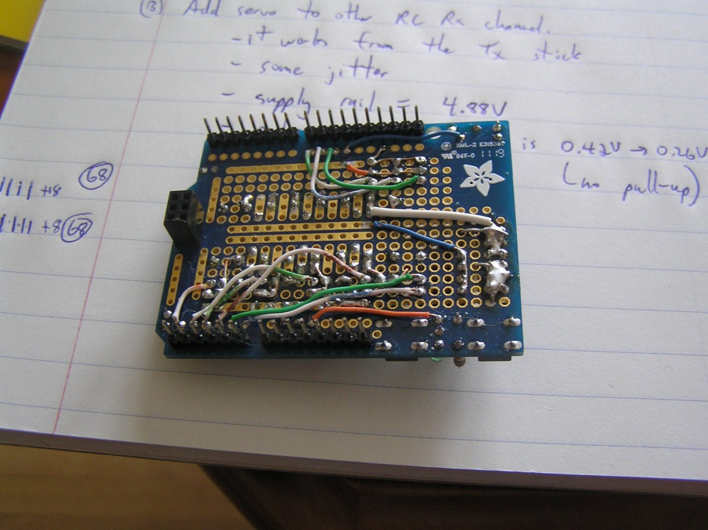
Yes, you can buy many Arduino "shields" as they call them; I call them daughter boards. Most of them are for a specific function eg motor controllers, or wifi access, or whatever. Mine is a general-purpose prototyping board that provides some +5V and GND rails, plated-thru holes dog-boned to the connector pins, a footprint for a small SOIC, another reset button for the Arduino since its button is now under the "shield", and a couple of LEDs one of which I use as a power indicator.
No luck at the library today; two books I saw on the website last night were checked out today! GRRR..
-
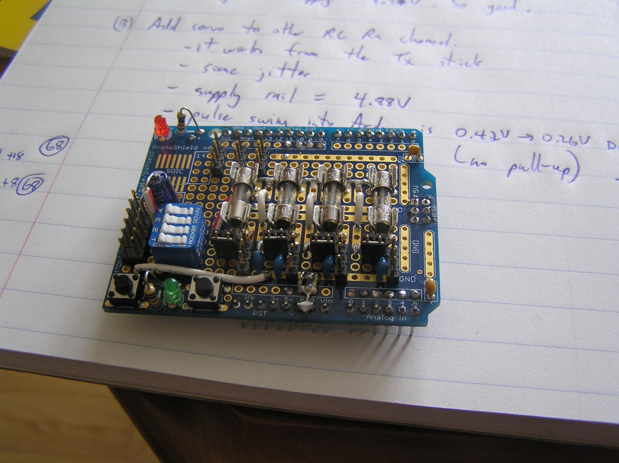
Finished the daughter board and finally started to, gingerly, try out some code. Here is what it looks like:
Four 3-pin connectors for the servos along the bottom edge; fuses are in but they are bypassed by the 2-pin jumpers; three 3-pin connectors for signals from the RC receiver (one for future use) near the top left corner.

Being a complete newbie I planned to take it in small steps. The first step was to verify that I could use the "pulseIn" command to measure the widths of the PWM pulses in the servo control signals from the receiver. This consists of literally two lines of main program loop - read the pulse width, and do a serial write to my monitor screen to tell me about it. Maddeningly it always returned zero after exceeding the timeout period waiting for a pulse to arrive. I went down several blind alleys, handicapped by my lack of an oscilloscope, but using my multimeter I was seeing the DC levels at the microcontroller pins vary as I moved the Transmitter's sticks, indicating the expected varying duty cycle.
Finally I asked about it on the Arduino forum. After some twists and turns, it came out that I was specifying the wrong pins at which to monitor for the signal! Being ex-engineer, I was looking at the schematic and specifying the pins on the microcontroller chip to which I knew I was connecting the signals; turns out that Arduino makes it simpler by designating "pin numbers" as the pin numbers at the connectors on the UNO board not those of the chip. They make the Arduino a true "black box" with the user not even needing to know what chip pin they are using - just call it by the board pin number or name and the compiler knows where it goes on the chip.
A true case of not knowing what I didn't know, if you follow me.
I plan to get an Arduino book from the library to see what else I don't know.
- RichardG, Nirvana, GrandpaPhil and 1 other
-
4
-
Hi Bill;
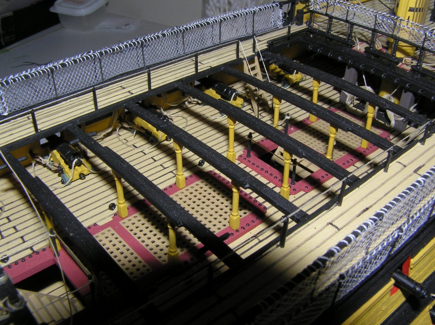
There are three pairs of ropes that pass thru the 1/4deck gratings beside and aft of the mainmast, specifically the mainyard jeer falls, mainsail clew garnets, and the main topsail sheets (refer again to the note at the top of pg267 "Belaying Plan Quarter Deck" with the line pointing to the gratings beside the mast).
These ropes are tied off at the main deck bitts part # 89 (two of them) just forward and just aft of the main mast, respectively.
It is much easier to tie these to the bitts and form any desired coils BEFORE the quarterdeck is cemented in, and either pass the threads through the quarterdeck as you are gluing, or after gluing, than to attempt to tie them off after adding the deck. That's all I meant to advise.
Longridge also has a photo, Plate 46 between pg196 and pg197, showing the bitts. The aft bitts receive the jeers and garnets, the forward the topsail sheets, as the caption mentions.
Note: on the old Victory web site there was debate about whether a larger gap should be opened in the gratings to allow these lines to pass through, or whether the gratings should be removed entirely. Not sure there was a firm conclusion; Daniel might have an update 🙂.
-
-
Just for laughs I pulled my SR out of the stash to compare the as-is stern bulwark to yours. WOW!!! What an incredible improvement!!! I will feel let down if/when I ever get to it......
-
-
Bill, Nelson's cabin needs a portrait of Lady Hamilton......😉
-
I've finally realized why "Capt Graham Moore" seemed familiar.
In "Hornblower and the Hotspur", Admiral Cornwallis detaches five ships to intercept the Spanish treasure flota under the command of Capt Graham Moore in "Indefatigable". Looking forward to reading about it when my copy of the book arrives.
Presume he was the soldier John Moore's brother..........
- druxey, thibaultron, mtaylor and 1 other
-
4
-
Yes, your main sheet looks good.
Your Cutty looks nice. Maybe I should consider trying to clean 40 years of dust off mine and then case it? For the most part it is still intact, some minor repairs required, although I wish I had painted the molded deadeye lanyards. Or perhaps I will build another someday with wood deadeyes. My Constitution is a write-off; for parts only.
-
Three titles so far.......
But look at this:
https://www.abebooks.com/9781503254336/Frigate-Commander-Supplement-Wareham-Tom-150325433X/plp


HMS Victory by Bill97 - FINISHED - Heller - 1/100 - PLASTIC
in - Kit build logs for subjects built from 1751 - 1800
Posted
No, actually those lashings to the ringbolts aft of the mainmast are the ends of the as-yet unrigged mizzen mast stay & preventer. I tied them off before even inserting the mainmast while I had easy access. You need to add these ringbolts too 🙂.
Longridge's Plan 10 "Belaying Plan" has the shortcoming that it does not show deck ringbolts for various rigging components.
Have a look at this photo below, which is from Hackney's little hidden gem of a book on how to model the Victory. This is a portion of his belaying plan, around the main mast, which does include deck ringbolts.
Rigging items #65 are the mainyard truss pendant falls. Eleven inch double blocks are lashed at deck level to the two deck ringbolts labelled 65 forward of the mast. The free end of the falls belay to cleats labelled 65 on the mast.
As I mentioned above, 9 and 10 are ringbolts for the mizzen stay and preventer.
Number 64 indicates the mainyard jeer falls coming through the deck.