


Ian_Grant
-
Posts
2,028 -
Joined
-
Last visited
Content Type
Profiles
Forums
Gallery
Events
Posts posted by Ian_Grant
-
-
-
Yes, you need to be concerned about breathing in ultra-fine particles which will enter your lungs. Especially if a model has some exotic tropical wood species.
The trick is to collect the dust before it scatters into the air. Have you heard of "suction boards"? Basically you build a box with a perforated top surface and a dust port to connect to some sort of shop vac. Simply sit your piece on the perforated surface and sand away. Dust disappears into the collector before it has a chance to scatter.
Of course, this still requires a shop vac but some of the small units are relatively quiet. It must be able to filter sub-micron particles or it will send your collected dust straight back into your room.
Hope this helps!
Here is an example video:
- thibaultron, Canute, kuya and 4 others
-
 7
7
-
Going to be beautiful. May I suggest you add "RADIO" to your title; that way all the RC enthusiasts will pull up chairs. 😀
Looked up Southern Cross Models. I see your 1/72 County class hull is 2.7 meters long !!!!!!

RC enthusiasts will definitely want to follow this!
Also, that deck and turret look very nice; are you 3D printing parts, or does Southern Cross models work up structure too?
-
Good God Bill! So sorry to hear about all that.....hope you both are fully recovered soon!
Best Regards,
Ian
- mtaylor and Bill Morrison
-
2
-
-
Marc, I see you went with a painted figurehead too, as opposed to all gilt. Nice!
-
3 hours ago, Kevin-the-lubber said:
<snip..snip> I'm reasonably okay with persevering with a difficult problem, less so with endless repetition.
Wait until I get to the ratlines .... 🤪
-
While responding to Kevin, I noticed I hadn't posted in a month. Still moving from mast to mast adding backstays. To break the tedium I added the boom and gaffs to the jigger and also installed the cargo boom. The monkey gaff still lacks a pair of guys.
Coils of pre-belayed running rigging accumulating. I'm glad I am omitting all buntlines! 😁
- Prowler901, Cirdan, Bill Morrison and 3 others
-
6
-
6 hours ago, Kevin-the-lubber said:
9” longer than the Victory is getting large - I guess that’s why they went for 1/150, so it’d still fit in the average house. I read somewhere recently that this was part of the general design brief for these larger models.
Its a pricey kit though, about £150 it seems, whereas the Passat is only £65. So many models…. I’d best finish the CS before getting distracted!
150 euro! I did not pay that but I did have to look hard for one, eventually getting it from France. If you would like to build a Preussen, a cheaper route is to buy a "Cap Horn" 5-mast barque kit and simply convert the jigger to square rig. This less popular kit is a made-up ship that never existed as far as I know but is otherwise identical to the kit Preussen.
Kevin, if you go back to post #12 of this log, someone had a kit to sell. Maybe they still do?
Or you can build Cap Horn as "Potosi" which did exist in the same Laeisz fleet as Preussen and was in fact handier to maneuver, being barque rigged. Bill Morrison is doing this as mentioned earlier in this log.
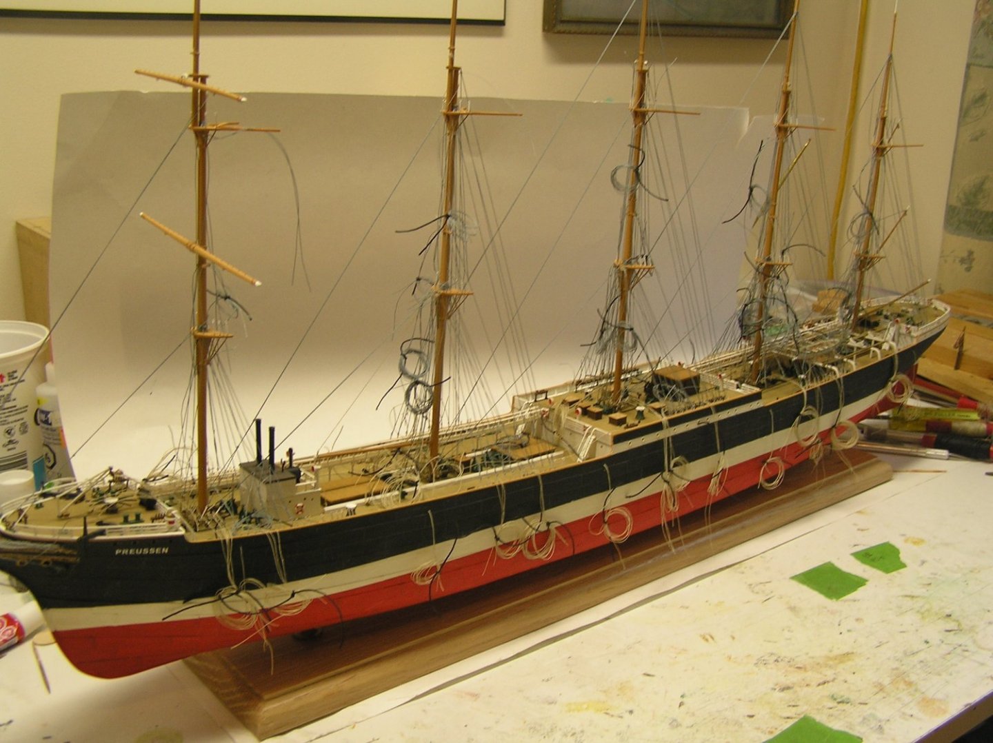
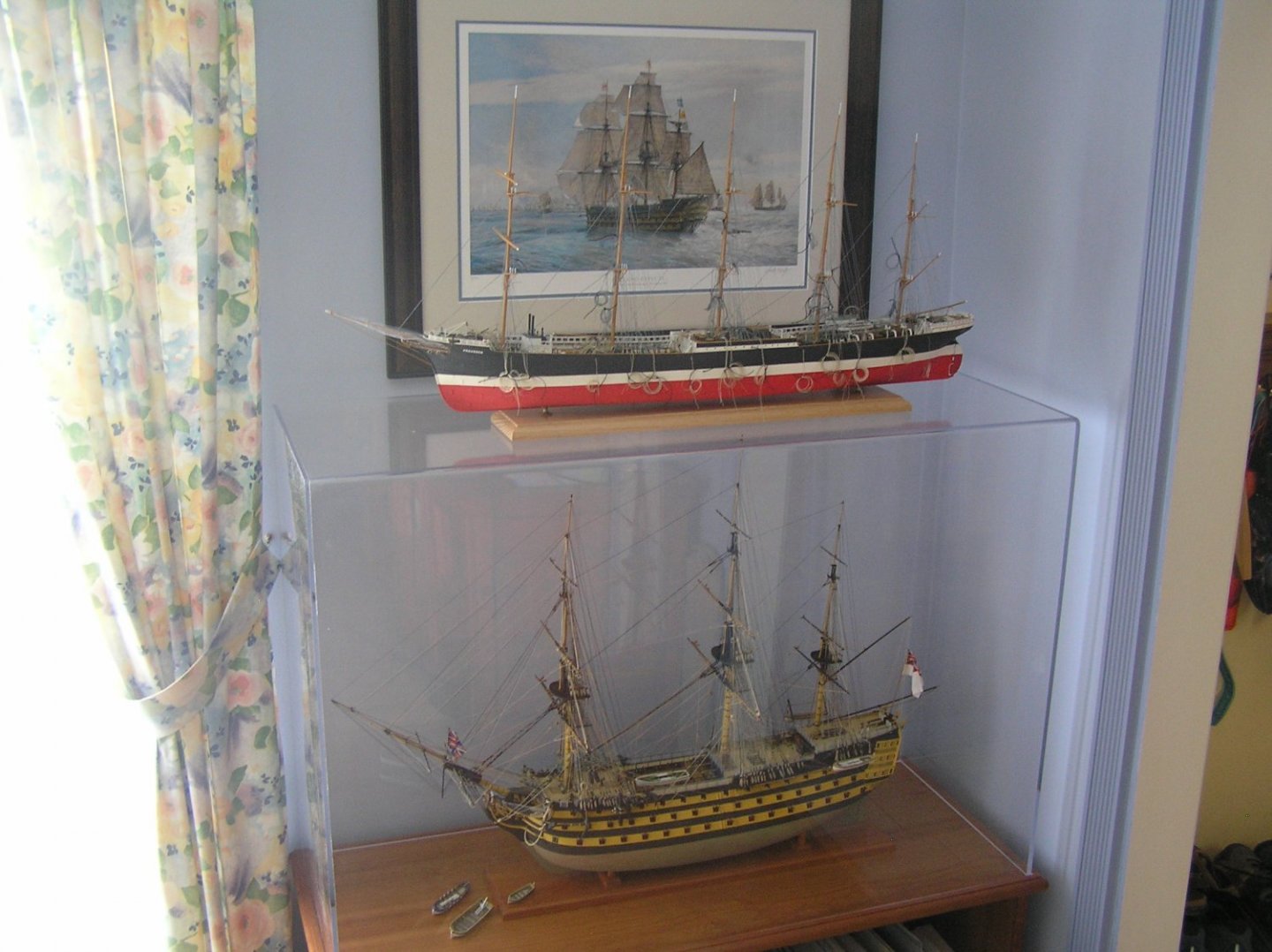
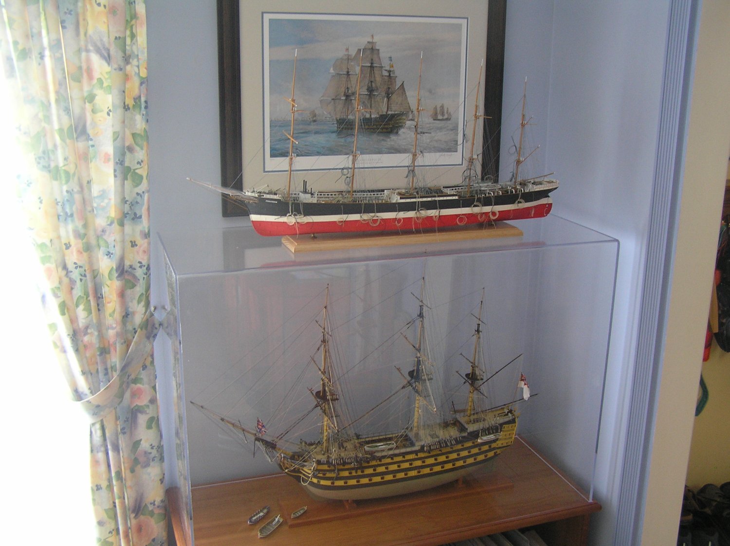
The hull is about 9" longer than Victory's hull, but their overall lengths are about the same. Preussen is a more compact finished model than Victory, much narrower and shorter. Here is a pic.
- Bill Morrison, Cirdan, Prowler901 and 1 other
-
4
-
Bruce, thankfully the Preussen lacks deadeyes which is a blessing at her scale. And these big windjammers had no studding sails.
I like your Cutty Sark progress, keep up the good work!
-
Kevin, thank you for the kind words. Yes, these big steel windjammers are quite picturesque. I especially like the elevated storm gangways, for some reason. And from some of the photos I've seen of these ships in a storm I can see why they were needed! Her hull is about 9" longer than Victory's, but the bowsprit is very much shorter than Victory's. A model of her at 1/100 would be magnificent and fun to build. Yes the scale is smaller, but her rigging is much less intricate than 18th century practice, albeit with everything repeated five times on her five masts which does get a bit tedious. The repetition will get even worse when I start hanging six yards on each mast! I haven't looked for build plans, but a chap named Neville Wade has built an RC model of her so he must have found them somewhere. Here are Neville's ships, not as detailed as some but very pretty on the water. After I get the galley working I'd like to build an RC square rigger next.
http://www.cocatrez.net/Water/NevilleWadeShips/index.html
Thanks for the Newby book tips - I'll have a look for them. And do look for "The Last Grain Race" for yourself. It's interesting, vividly written, and funny at times.
-
On 5/20/2022 at 9:24 AM, Bill97 said:
OK my fiends, as Kevin said above, I am moving into stage 3 of my build. The running rigging. As with the standing rigging I plan to read through the section in Longridge’s book on running rigging before I get started. My initial impression is that I need to install the yards first before I can do any of the running rigging? Is that correct? Would seem to be correct since all the running rigging deals with the yards and sails. Or, is there some of the running rigging I should complete first before putting the yards on. I know I want to prepare all the blocks on each yard off the masts, and plan to do that.
Bill, just thought of the head sail rigging. Granted it's on the axis of the ship but the halliards need to be belayed on deck. You could usefully complete the various downhauls and halyards before moving to yards and other running rigging.
In my case I am nearly done the standing rigging on my "Preussen", but in accordance with "The Ian Grant Method of Ship Rigging" all the running rigging is already belayed on deck to prevent a lot of special words while trying to tie off after all the backstays are in. See all the coils hanging over her bulwarks, here. Some from mast bitts, some from bulwark rails, some lower sheets and tacks.

-
3D printing is amazing, the way of the future for sure. I can't get over how quiet she is! I last launched an electric RC boat in the 70's using brushed Decaperm motors of the times; you could easily hear the motor whine from shore. I was thinking of maybe refurbishing my old WW I battlecruiser (which last sailed in 1980) with ESC's to replace the rheostat speed controllers but maybe I should change the motors too, having seen this.
The Decaperms were geared motors; do you need to add a reduction box for these new brushless motors?
- Canute, NavyShooter, lmagna and 2 others
-
5
-
Servo selection done - the sweep servos will be Hitec's model HS-755MG, a "giant scale" or "1/4 scale" (depending on who you talk to) analog servo where "MG" stands for metal gears. The other contender was the HS-645MG standard-size servo, which would have had less margin over the expected RMS torque. The 755 rotates 90 degrees with the typical RC set's 1000 to 2000 usec pulse range but can rotate up to 200 degrees given a wider range (570 to 2400 usec is the extreme, according to Servocity). Since I have the Arduino controlling it I can easily provide 870 to 2130 usec or whatever, to get it to rotate 120 degrees. Then as discussed previously the arm can be short, minimizing the torque.
The final nail in the 645's coffin was that the 755's different motor actually draws less current while providing 50% more torque. I think I said earlier that I'd rather have a bigger motor loafing along than a smaller motor labouring; with the bigger motor drawing less power it's a no-brainer.
I then needed to design the oar position angles for power and return strokes. Pulling out my Pitassi I was reminded that his quadrireme interpretation had 88 oars, not 80, so my remes will be 22 not 20. This will increase torque 10% but I had already decided on smaller blades for appearance so torque is only about 3/4 of what I said in earlier posts.
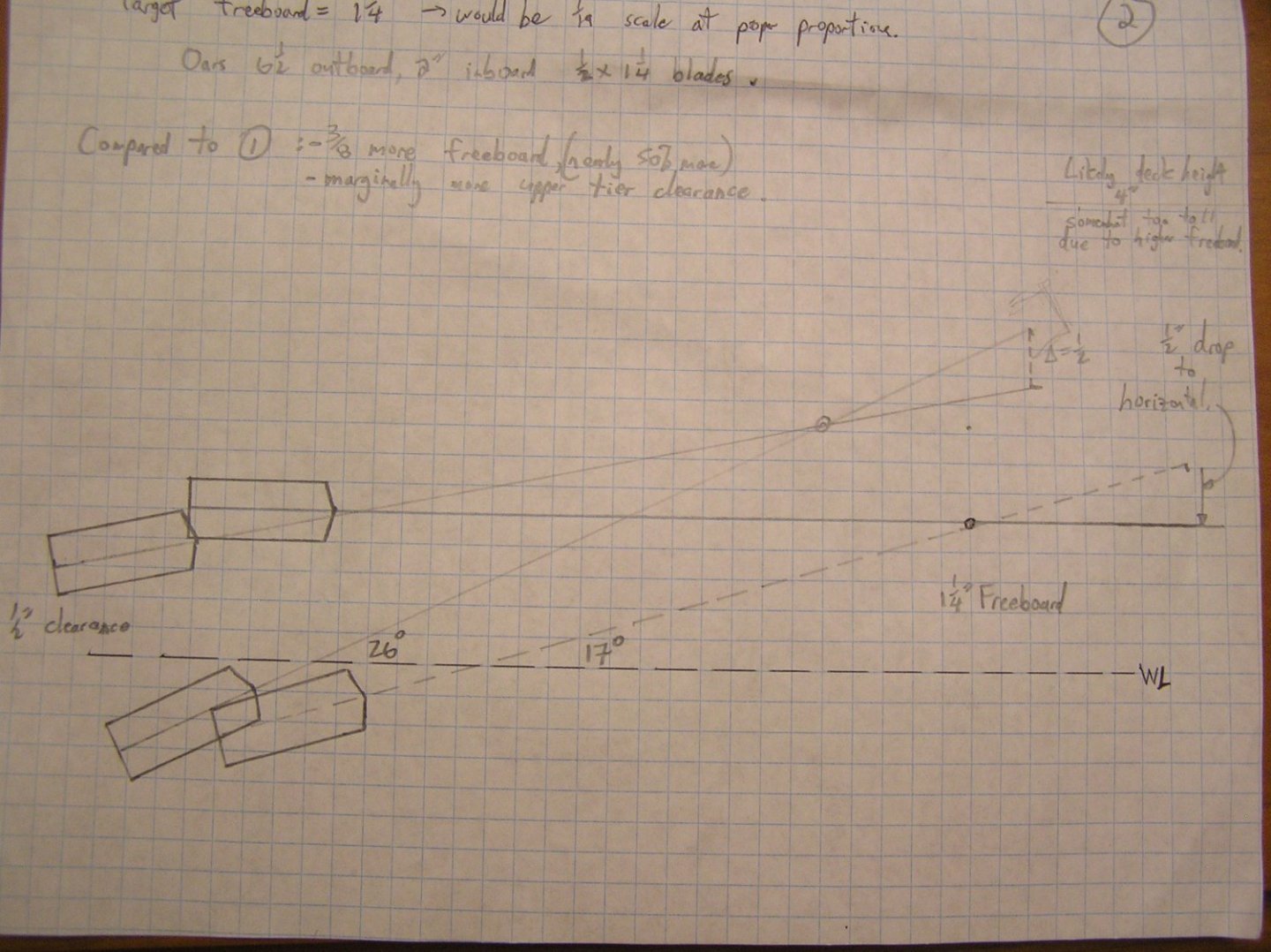
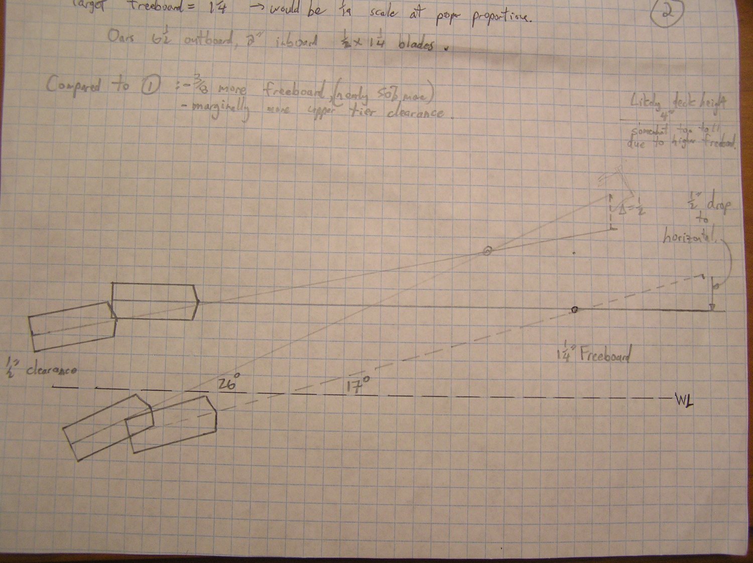
I spent some time manually drawing the oar angles wrt the waterline given the outrigger size. I found that it's not easy to have both remes of oars in the water for the power stroke and still have decent clearance above the water for the upper reme of oars during the return stroke; in a real ship the rowers in the upper reme could just lift their blades more than their buddies in the lower reme, but my mechanism will move the looms of both sets of oars the same distance vertically. It seems I will need to have the lower reme come up to horizontal in order to have clearance for the upper reme. Also, I'd like to have a little more freeboard than scale (which is only 3/4") but this makes the oar angles steeper which increases the above difficulty. I finally came up with a drawing with lower oar hole centres 1.25" above the water, with upper oar tholes spaced 13/16" higher, and 1.25" more outboard. This will lead to an upper deck somewhat higher than ancient writers imply for a quadrireme, but what the hell. I was surprised to find that I only need about 1/2" of vertical movement at the looms. Here is the drawing:
I could go on forever making manual drawings so I decided to use tinkerCAD to model the mechanism with Servocity parts. I still can't figure out how to import Servocity's STEP files into tinkerCAD, and I don't want to spend months swearing at Fusion360, so I just drew the parts manually in tinkerCAD. Still required a few special words. 😁
I drew it with linear bearings since the available 2" long bearing now seems about right. My main purpose is twofold: (1) see how far below the waterline the drawer slides need to be, in order to design the central bulkheads, and (2) determine how far towards hull centreline the mechanism reaches i.e. how much space in the middle (needed!) for battery or servos?
Here's what I have to this point. This drawing shows two upper reme oars and one lower reme oar with blades in water. Also two lower reme oars in horizontal position. Oar angles when in the water are 17 and 26 degrees respectively, a bit higher than Pitassi's 12 and 19, because I have the extra freeboard.
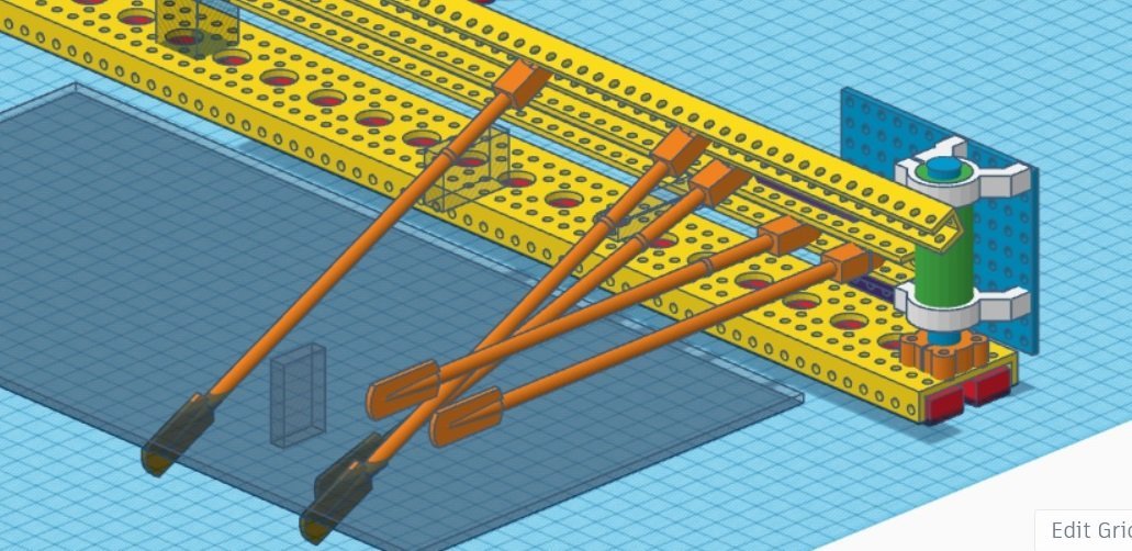
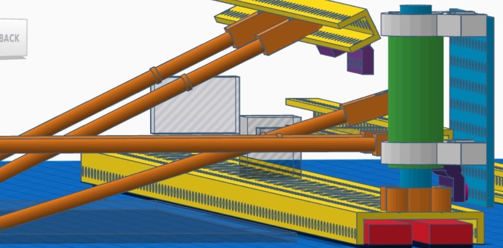
From the bottom, we have the red drawer slides, a yellow "low side channel", an orange clamping hub, a blue SS shaft clamped in it, a green linear bearing, white clamping mounts around the bearing, a blue "back plate" which forms one end of the oar beam and which slides up and down the shaft thanks to the bearing, purple hinges connecting yellow u-channels to the beam, orange oar pivots within the u-channel, and orange oars. I haven't represented the other end (similar), or the L-channel beams which will connect them. The hinges on the upper reme will connect to the beam via standoffs (not shown) which will place the upper oar looms correctly relative to the lower (given the outrigger dimensions).
So far I've concluded that the bottom faces of the drawer slides only need to be about 2mm below waterline, not as much as I had feared. The mechanism intrudes about 2.6" into the hull meaning that I only have about 1.8" free in the middle of the 7" beam hull. Probably ok for a battery and maybe the lift servos.
I'm also finding that it is not so easy to place the second reme's hinges exactly as required; I had blithely assumed that if I tweaked the spacing from beam to hinges, and used washers as necessary between hinge and u-channel, I could get the oar looms to be anywhere I liked. Not quite that simple.
Further tinkering required. It would be cool if I could animate this. Dream on.
- mtaylor, Keith Black, GrandpaPhil and 1 other
-
4
-
Hey, I was born in Paisley! Parents emigrated when I was four. My brothers and I went to see our old address when we went backpacking years ago.
-
Me again. Just thought about the mainstay tackles. They make an interesting little addition to the model. I don't think Longridge describes them in text, but there they are in the "Standing Rigging" pull-out, dangling from the main stay. If you want to add them, it may be easier now than with all the yard ends poking out at you. 😉
-
Bill, one thing that comes to mind is the numerous lines that tie off on "shroud cleats" especially at the fore mast. You should figure out what you're going to do about them. I formed shroud cleats from etched cleats and very small pieces of evergreen and tied the lines to them before attaching to shrouds; my usual reverse-rigging method. This avoids having to reach across the ship to tie the lines off.
Of course you could just tie them to the shroud. At the end of the day it's very hard to see.
-
4 hours ago, shipman said:
Yes, all the kits back then were derived from a larger 'master' model and a pantograph system was used to make a mold.
Airfix used to highlight the process in their magazine, Revell did something similar as part of their publicity.
I'll try and dig a bit for that.
That would be interesting to read about!
-
6 hours ago, Tony Hunt said:
Diagonal planking (cold moulded) does make a really strong, light hull. My late father built some very large sailing models of iron-hulled square-riggers using the technique. The model in the picture below, the County of Inverness, is about three metres long and is double diagonal planked in NZ Kauri, over frames and longitudinal stringers.
Over 3m long........gorgeous.........now we're talking. I drool over such large RC models in "Introduction to RC Scale Sailing Models" by Vaughn Williams.
-
All the guys I see at my local model shops are older. By and large the new generation just isn't interested, or has no exposure to dad at home making things. Nor do they get shop classes at school any more, at least here in Canada. Around 1970 or so, we were brazing with oxy-acetylene torches in grade 7 or 8 shop class. Today, nada; liability you know.........
The world has moved on. My dad's trade of tool and die maker now features CAD'ed CNC-everything, not the experienced tradesman cutting from a drawing in such a way that the gear backlash effect is minimized. And you're now considered a cabinetmaker if you can lift melamine panels off the router table and run the edger machine to tape the exposed edges.
There are maybe six people in Ottawa who make sailing ship models; I don't know any firsthand. I doubt manufacturers could recoup their tooling investment if they made a new ship model. It's sad, but 3D printing is on its way to help those interested. Soon we will make our own kits with software. Just the same route blazed in so many other areas.
-
Being a teenage boy when I built the CS in the 70's, I painted Nanny with flesh colour and dark hair, and two tiny dots of red paint for nipples. Sheesh.
If I ever refurbish her (the CS) job one after cleaning will be painting Nanny white. 😀
-
Thanks gentlemen for mentioning this. I've added a note on pg 1 of my SR instructions, for when (if?) I get to her.
Cheers!
-
-
You asked in Kevin's log about how the stays are attached to the masts. For the lower masts, they are usually double, looped around the mast head and seized together close to it. Also seized near the bottom, close to the rigging screws or whatever each side of the mast ahead. Those on topmasts are double, seized together too. For topgallants, they are single and a tight eye is formed and seized and forced over the masthead.
If the Revell instructions show a loop with a knot at its neck, they are correct. They're not meant to be tight to the mast, except in the case of topgallants/royals.
You seem to be a guy who wants to produce an accurate model. I recommend "Masting and Rigging the Clipper Ship and Ocean Carrier" by Harold Underhill. Excellent book, many many diagrams.


Christiaan Brunings by Richard44 - FINISHED - World of Paperships - 1:100 - CARD
in - Kit build logs for subjects built from 1851 - 1900
Posted
I'm a bit late to this build, but very impressed! Between you and Chris I am thinking I should try a card model of some sort; will have to look around to see what appeals.
Happy modelling!