


Ian_Grant
-
Posts
1,650 -
Joined
-
Last visited
Content Type
Profiles
Forums
Gallery
Events
Posts posted by Ian_Grant
-
-
On 11/30/2020 at 5:32 PM, Harvey Brandt said:
Where can I buy brass eye bolts
You can buy Caldercraft copper eyebolts almost exactly the same size as Revell's plastic versions at many hobby suppliers, for example:
- popeye the sailor, Canute and mtaylor
-
 3
3
-
-
-
Paul, I too needed some replacement parts for a Heller kit. On the German glow2be.de website, click on "service" then "spare parts form" then select excel or pdf version. Being old school, which you can read as simply "old", I selected pdf and printed it. I filled in the part info and my address etc, scanned it and sent it to the address given on the form, "mail@glow2be.de" which resulted in a very long complex "undeliverable" message. If I understand it correctly, the "glow2be.de" server did not/could not pass along my message to "mail" because (a) it may not be an office365 server (?), (b) it cannot accept messages from my "domain", by which I guess it means Canada, or maybe North America??
Whatever, I found a FAX machine (old tech I thought only the medical profession was still using) and instead FAXed my message to the FAX number also given on the form. I just got a reply, after two business days, that my part is on the way free of charge. Customer service!
By the way I replied to the nice lady to inform her of my difficulties contacting "mail@glow2be.de"; perhaps they will be able to fix the issue.
-
Mark, thanks and yes, I'm familiar with Daniel's work from the now defunct Pete Coleman site devoted to the Heller Victory. I had the pleasure of buying some of his brass etch to enhance my build.
My favourite Daniel build is:
https://modelshipworld.com/topic/349-sms-trinkstein-by-dafi-sos-stone-on-soil-flush-deck-frigate-of-the-austrian-mountain-navy/?tab=comments#comment-3313
-
There are some brass etch gratings here:
http://www.dafinismus.de/plates_en#anker7
Scroll down to Plate 8 which contains three grid sizes; perhaps the largest would suit your scale? If not I would ask Dr. Google for any others.
-
Me again! I should also mention the appalling rigging instructions, or lack thereof. I don't know if you were aware of this. The separate Revell rigging instructions are a joy to follow, all laid out neatly and in a logical sequence. Heller has scattered rigging "instructions" all through the assembly manual in nearly illegible print. In order to see where a rope goes, one must find its two ends which could be on any pages whatsoever.
I cannot stress enough to you that you should buy a book as a rigging guide. The "bible" for this is "The Anatomy of Nelson's Ships" by Longridge. It has many beautiful diagrams and separate descriptions of each rigging line complete with rope and block sizes. There is also a much smaller book, "HMS Victory Classic Ships and how to model them" by Hackney. This book is geared to enhancing the smaller Airfix model but it also gives rope-by-rope instructions albeit with less impressive diagrams. The "bible" mentioned above is much much thicker but much of it is concerned with scratch building a wooden hull and masts which is of little use to the plastic modeller. The rigging part boils down to the last 65 pages. Either book will inform you of additional ringbolts and blocks which must be mounted on the deck in order to properly rig, for example, lower yard truss pendants (I mentioned in my earlier post that Heller provides no instruction as to how the yards are attached to the masts) LOL.
As I said earlier the provided deadeyes and blocks are useless; aftermarket wood parts should be acquired. I recommend Syren wood blocks. In order to properly rig her you will need about six block sizes, in singles doubles and occasionally triples, and five or six sizes of both black and tan thread.
Finally, there are eight brass etch sheets available to enhance this model. I highly recommend at least the two containing deadeye chains and preventers (Heller provides none), and stanchions (the brass parts have actual eyes for threading whereas the plastic parts do not).
Brass etch can be viewed at http://www.dafinismus.de/index_en.html ...click on "...parts for the Heller kit".
Sorry if all this is known to you.....I don't know if you have made models other than the beautiful Revell ships you showed us. The Heller "Victory" is a whole new ball game. Looking forward to your build log!!!
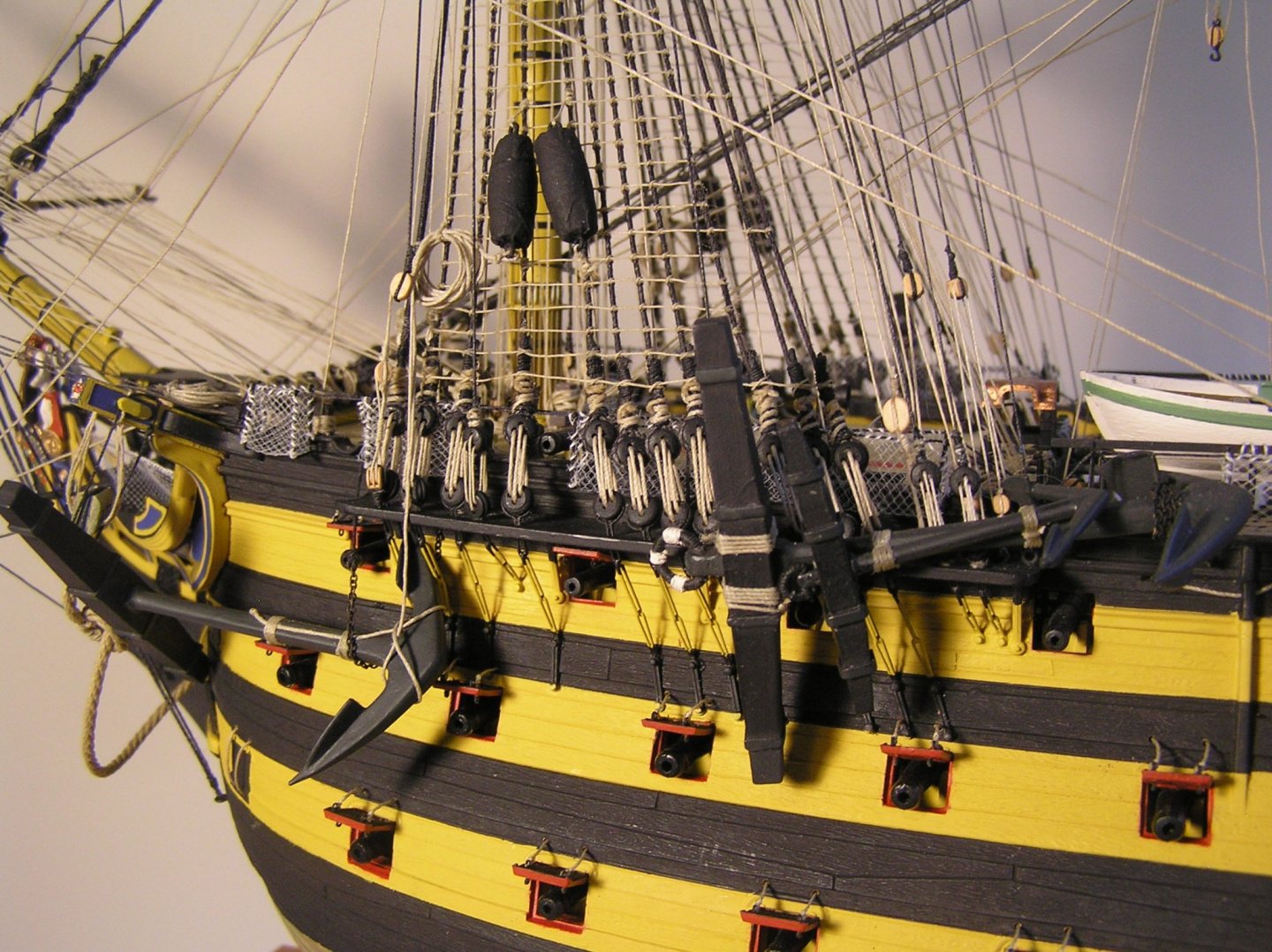
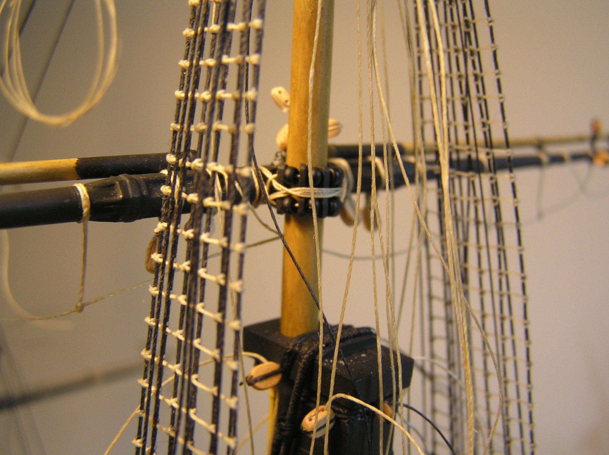
PS Here are some shots of a home-made parral; brass etch chains in place; brass etch stanchions.

-
Nice display, Bill !! I made the Connie and Cutty Sark in high school back in the seventies. I still have them although I decided to scrap the Connie a year ago; for some reason I gave the sails a green/brown wash and I came to realize they look mildewed. The bosun would be hung for that!
I used a couple of the upper yards as donor yards for Victory's fore and main royal which Heller do not provide. They're lashed inside the topmast shrouds for stowage.
I don't know how much you've looked at your kit, or know about various problems found in certain Heller ship kits, but as forewarning here are some other things Heller do not provide for Victory: fore lower studding sail booms; any and all yard parrals; stream and kedge anchors, and buoys; fish davits; usable deadeyes and blocks; usable thread.
Looking forward to your build log; it's always nice to see another Victory come together.
-
Steven, thanks for pointing me to this build log. What a great model! I was greatly interested in his linkage design at the oar looms and the racetrack operation.
LATER EDIT: the following paragraph was augmented.
A large part of the complexity of my all-mechanical pseudo-design (I priced it at about $300 worth of parts from servo city!!) was driving both sides from a single motor so the oars on the two sides would be perfectly in sync when rowing straight, yet allowing for moving in opposite directions when turning. Bensid remarks several times in his videos that he has trouble "driving" his galley and I think it stems chiefly from having two motors drive the two sides with no means of having them run at exactly the same RPM, and even that does not guarantee the oar beams would be in sync as well. Very difficult to achieve with a purely mechanical solution.
It was shortly after that I read (somewhere?) about the Arduino/servo system. The two sides can be kept perfectly in sync because the Arduino is sourcing all the servo PWM streams. Again, and this is huge, there is no need for any racetrack or other way to shape the stroke because servo interaction defines it. I did not go to the lengths of sketching a possible mechanism but after watching these videos I can see maybe needing two servos on each side for the up/down motion; one at each end of the beam and plugged into the same Arduino output channel with a Y-harness, filling the function of the drive-belted sprockets. Still the same Arduino requirements: read two PWM streams and generate four.
I should add that as some people have mentioned, a drumbeat would be cool. Well an Arduino could also be programmed to automagically drive a speaker with a sound burst once per oar stroke.
It is to dream....
-
Richard, what a wonderful model! The planking is superb! I have contemplated in my wildest dreams making an RC galley. There is a picture of a large model "Liburnian" galley in Vaughan Williams' "Introduction to RC Scale Sailing Models". They don't go into the rowing mechanism though.
I actually went through the exercise of designing a mechanical drive to provide an oval motion. It was quite complex since you want the oars synchronized on both sides when rowing forward or backward, yet able to be reversed on one side for rapid turns. You either need mechanical reversing mechanisms or a way to synchronize two separate motors (I picture microswitches with momentary contacts which are pressed by the oar beams at the end of their stroke, generating pulse streams which could be put into the phase detector of a PLL whose filter output controls the speed of one motor to exactly match the other; doable but unwieldy because the PLL would have to be incredibly slow with such infrequent phase updates from the uswitches). Then I saw somewhere or other a different idea:
Have four fairly high torque servos. The oar drive beam on each side is driven by two servos; one to provide the back-and-forth motion, the other to provide up-down motion. And this is the clever part ----> you plug an Arduino board into your RC RX to read your "throttle" and "rudder" channel PWM streams, and program the Arduino to provide four PWM streams for the four servos, with each oscillating back and forth to provide repetitive oar strokes. So for example, if you push your "throttle" stick to "full ahead" the oar drive beams on each side move quickly, in unison; if you move the rudder right you can have the Arduino slow the right-side beam down, or stop it, or even reverse it given a sharp rudder stick position. It's all controlled by the program you write which can be in BASIC to keep things simple. You can design the PWM streams to the "stroke" and "elevation" servos to give elliptical motion or any other you care to experiment with. Arduinos are available with multiple PWM generators (where you simply enter the period and duty cycle). No electric motors, no drive belts etc.
LATER EDIT: I read up a bit on this topic as I am seriously considering making an RC galley next. It's actually PIC microcontrollers for which there is an available BASIC compiler. Arduinos employ "arduino" language which is a sort of "C" coding. I know zero about "C" but the Arduino commands look pretty simple; for example once you declare an internal timer is to output a PWM stream and set up the clock to get a 50 Hz repetition rate, a simple write of an integer value into a register sets the PWM output's duty cycle and hence servo position. All one needs to do is to write gradually increasing or decreasing integer values at regular time intervals and the servo arm sweeps accordingly. The Arduino "Nano" board sports up to six PWM outputs and several analog inputs to an internal Analog-to-Digital converter which could be used to read the DC value of the throttle and rudder outputs from the RC receiver, suitably low-pass filtered by an external R-C circuit you provide.
From my brief reading, getting started with an Arduino is easier than with a PIC; just my novice opinion. The Arduino Nano measures 18 x 45 mm, draws 19 mA, costs less than $25, and is hooked up to your PC via a mini USB to download programs you write using the user friendly and open-source Arduino IDE (integrated development environment).
It's still in the back of my mind for when I finish my current static model, but I also would really like to make an RC square rigger. Around here a square rigger would draw a lot of interest, but a galley would be unique I am sure.
I'm interested in how you joined the oars to the drive beam. I wondered how to have them attached, able to rotate at the joint during the stroke, while being unable to spin on their axis and throw the blades off vertical. At one point I pictured U-joints as used in RC electric motor boat prop shafts but it would cost a fortune to buy multitudes of them. Can't quite make it all out in your video.
I will follow your log with great interest. Thanks.
-
On 12/28/2020 at 3:06 PM, DanielD said:
Exciting day, I finally received my copy of James Lee's The Masting and Rigging of English Ships of War 1625-1860! This book can range from $50-$350 US, so I waited and looked, was patient (at least for me) and finally found one in the states for $80. Thank you ClearWay for pointing me to the AbeBook store as that is where I finally was able to find one close to where I live. Now to find time to read it...
Daniel, fantastic job on this your second wooden ship. You have an innate skill; I've never dared try one. I noticed some talk of suitable books for rigging. I have Lees and it's very good, but you might also like "Rigging Period Ship Models" by Lenarth Petersson. This much thinner and presumably cheaper book has an illustration on each page of one particular part of the rigging of HMS Melampus built in 1785. May be too early for your Terror model, but it's a great book for learning the names of various ropes and how they are rigged for future models.
-
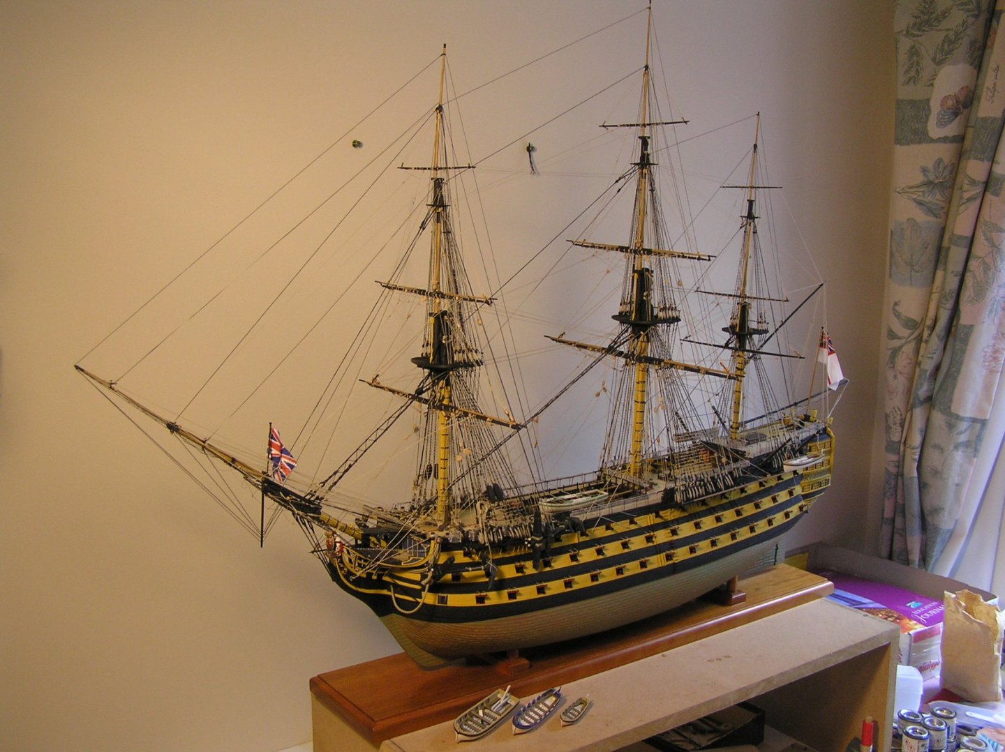
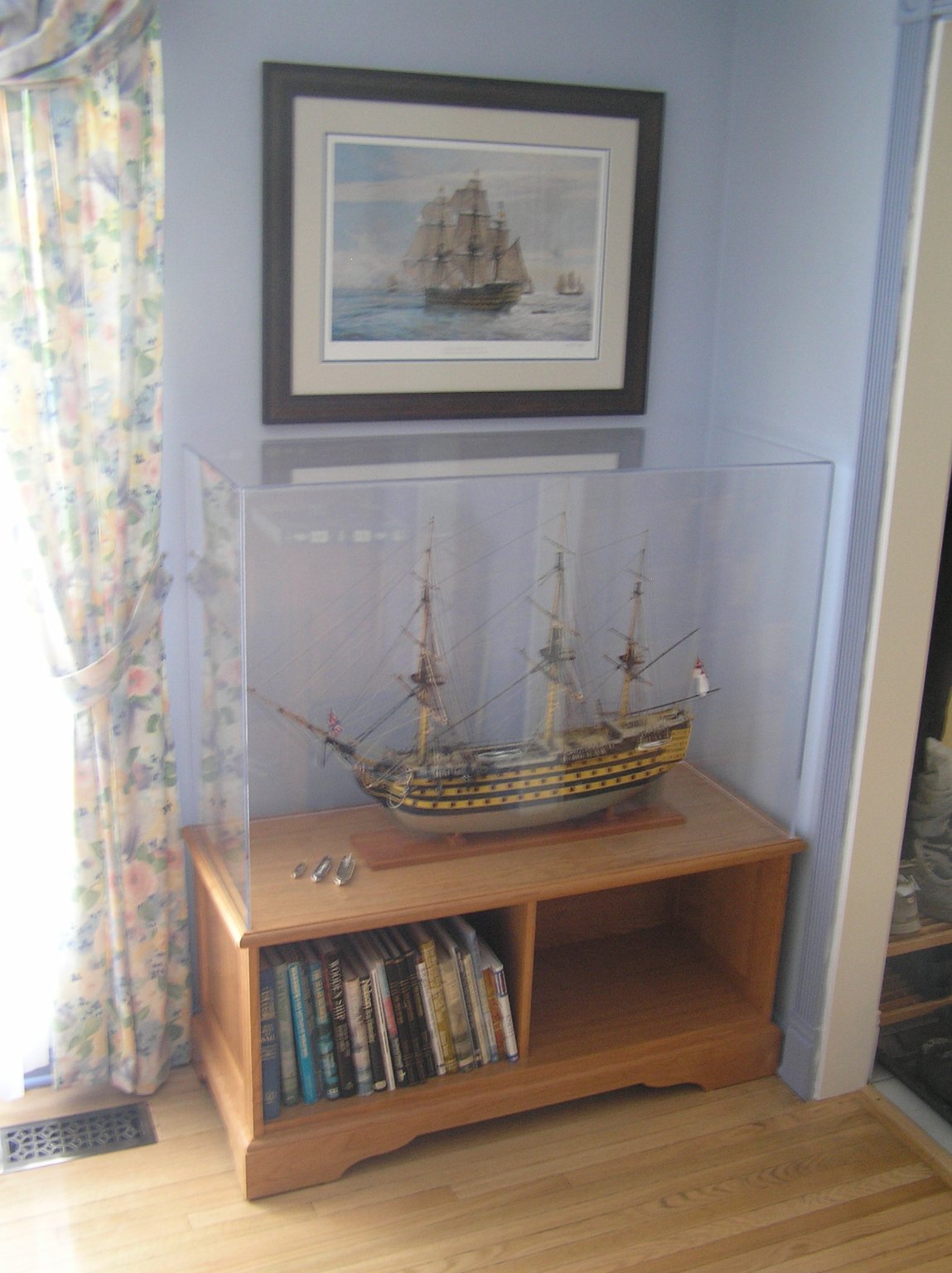
Yes, I can see those numbers on the internet too and no wonder Bill is confused. I can assure you both that Victory is more than 6" wide. That might be the hull itself, maybe (?), but the main yard with studding sail booms is much longer. The width I gave was for my model which is "bare sticks" with booms stowed. If you want to rig it sailing with studding sails set it would be much wider.
As for the 44" long I don't know where that comes from either. That value exceeds the length of my case which has 1-1/2" to 2" of space at each end of the model. Perhaps if one had a large flag streaming aft on the ensign staff?

- Canute, mcpwilk, GrandpaPhil and 2 others
-
5
-
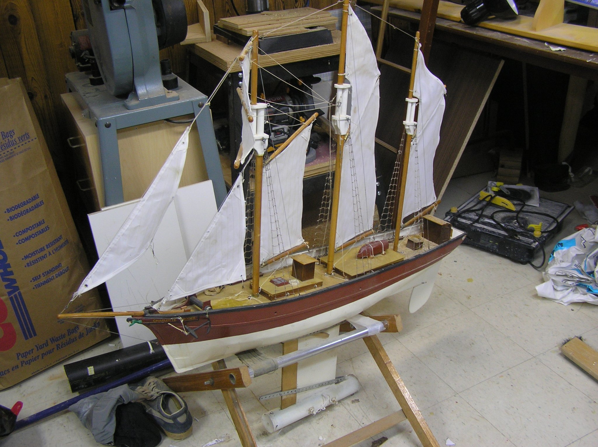
I built a rather larger motorized German Panther tank when I was a kid. In my teens I got into RC boats, then RC sail. My peak came when I scratch built an RC schooner. Needing a winch to control the braces of the square topsails, I ripped the drive assembly out of the Panther and mounted it under the main hatch, as here:
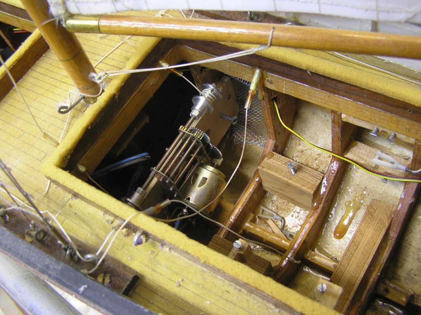
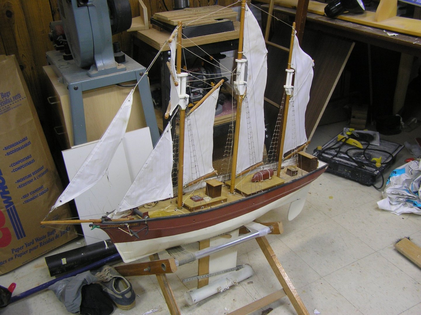
This photo was taken a while ago, after many years of dust-gathering by the "Charlotte Rhodes". The model would not tack properly; I decided I had placed the fin too far aft; I then left for university and the model never got wet again.
By the way for the fore-and-aft winch I used my monstrous sail winch from the 80's which generated about 21 lbs of pull but was about the size of three hockey pucks. How times have changed!
Here is the whole boat. It was clad in 1/32" plywood soaked in water, my mom made the sails. Not bad for a teenaged kid. Good times!
- Egilman, popeye the sailor, lmagna and 5 others
-
8
-
Kevin that's pretty amazing looking for TinkerCAD, love all the leafy greenery and I have no idea how you did that.
Funny you should mention the SR. When I finished Victory I had a stash of two ships to choose from: Soleil Royale and Preussen. The SR is beautifully engraved but there are as always it seems with Heller's ships some big problems. The underwater hull is hard to believe; there seems very little "curve of the bilge" near the stern meaning there's no buoyancy right where the hugely tall and presumably heavy stern juts up. The topmasts are too long, and the crosstrees are an odd construction to my eye.
Anyway I decided I couldn't face another 5-year build so similar to Victory (100 guns, deadeye rigging, mods required) so I started on Preussen. It will be another beauty when completed.
As for the SR, when the time comes, I'm torn between her and building an RC square rigger. I would love to have one, I still have my 50/800 sailboat I sailed in my teens. If the SR it will be a waterline build, or I'll cut the underwater hull off and add a "strake".
I may not have enough years left to do both 🙂
-
Hello Kevin! You won't remember me, but we joined Pete Coleman's website on almost the same day and exchanged a few messages. Glad to see you're back on the build; I had wondered where you had got to! I was just finishing my Victory as Pete's web site disappeared so I put a few build log pics on here. She took me 5 years so you are not far behind ;-)
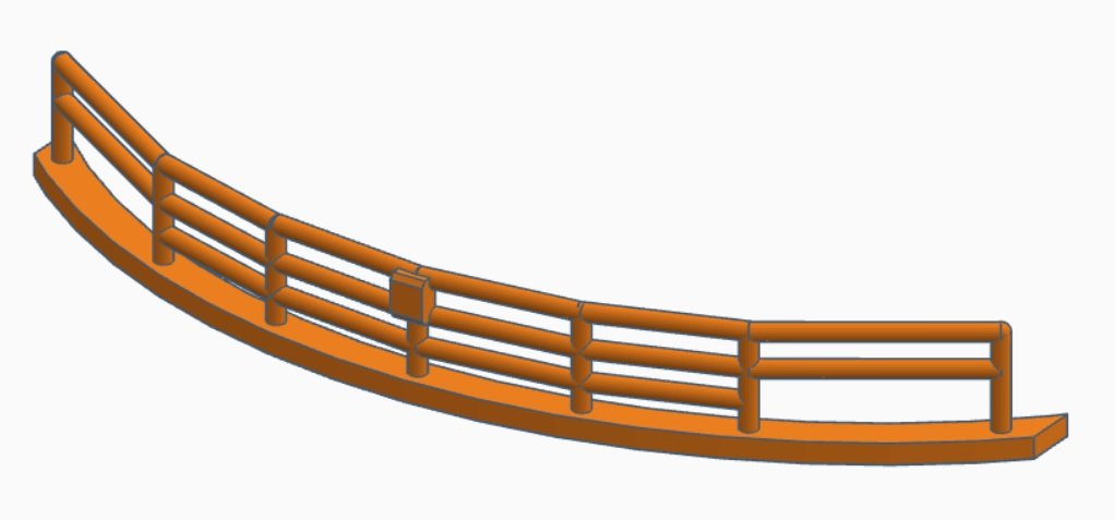
Your printed entry port looks great! I am currently working on a Heller "Preussen" and trying to get some 3D printed parts too. In my case my brother is the one with the printer, albeit 400 km away. In this kit the ladders are deficient plus my stern railing was bent and broken so I used TinkerCAD to draw some replacements. Hope they turn out as well as yours! I suppose you're using more advanced mesh software?
You're bringing new ideas to the Victory kit. Will be interested to see what you come up with next.
Best Regards,
Ian
-
-
Just for laughs I worked on a Jarvis brace winch in TinkerCAD. The supplied Heller winches seem too low down to me; it's as if they forgot that sailors need to crank them around too. I drew a winch which provides a crank at the same height as the wheel on the halliard winches, and made the overall assembly about 1.5mm wider (viewed from the sides) after first ensuring that there is clear deck space for this slight enlargement. I kept the width athwartships the same so as to use the same two mounting holes in the deck.
Here is a screenshot. It is sitting on a 1mm grid so you can appreciate how tiny it is. The different colours are components I envision as separately printed before final assembly. The yellow represents some 0.6mm OD brass rod.
Of course it's one thing to draw it and another thing to successfully print it. Opinions on odds of success, anyone? Haven't shown it to my brother yet as he's a busy guy and I am already waiting for the railing print 😉 God knows how the gear teeth would turn out. And before I receive a flood of messages, yes I know the gears could not mesh with their flanges as depicted; I wanted a circular base on which to print each toothed gear. I could have flipped the central large gear by making it another distinct part, but at this scale why bother? And they may prove to be totally unprintable anyway.
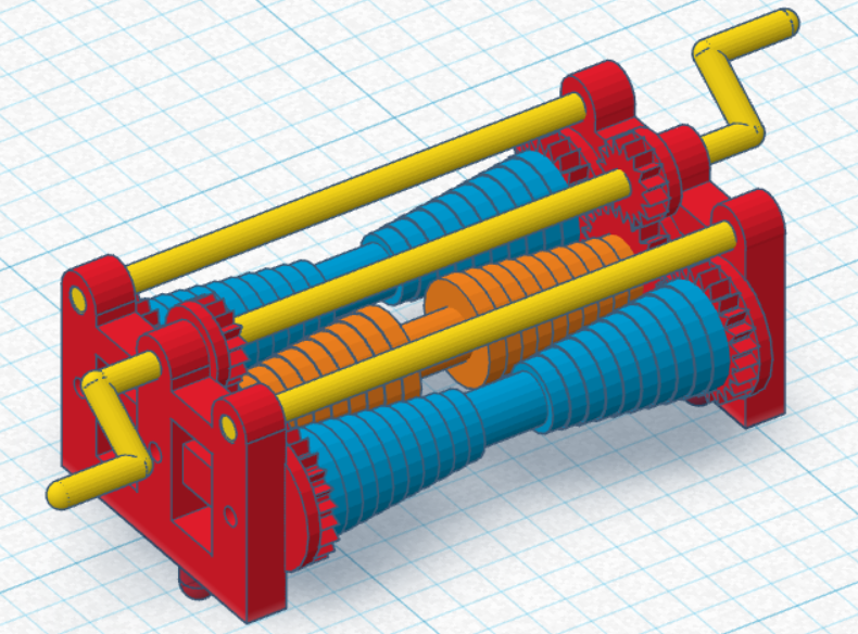
I messed around for pretty much an entire day on this, more than I wanted to but the CAD brings out the ex-engineer in me. Gears are none too easy to draw in TinkerCAD as I couldn't find a "primitive" for them. Perhaps there is one in there somewhere but mine are a manual effort.
-
I've been quiet for a while due to reno jobs; one lady hired me to make her a dresser which was quite fun as furniture commissions are rare for me.
I have been working on solving two nagging Preussen problems i.e. Heller's unsuitable ladders, and my ruined stern railing. I've emailed Heller four times about a railing replacement without any reply. The ace up my sleeve is that my brother has a 3D printer so I decided to try to create CAD drawings for these parts. I used TinkerCAD which is a free online CAD tool. After watching a few tutorials (not those provided by TinkerCAD which are useless for a neophyte) I was able to produce some .stl files which I sent to my brother to print. He says the ladders came out clean, though he was laughing at the tiny amount of filament required (3 cents worth for a dozen ladders), but I only just sent him the railing file.
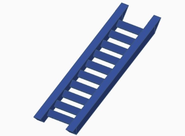
Here are some screen captures of the 3D drawings.
This is a modified Heller ladder in which I just added some triangular wedges at the ends to orient the miters in the correct direction.
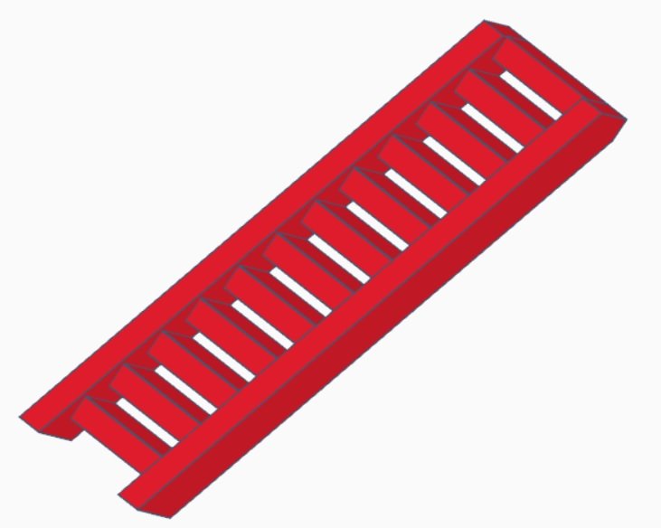
This is a ladder inspired by those in the pictures of the Preussen model Miki sent me above. I drew it after measuring the total rise with calipers since Heller's ladders seem a tad short. The upper step is meant to be flush with the upper deck it runs to as in the model.
Here is my rendition of the stern railing. Unfortunately I could not get the "torus" shape to work for my tubular rails because when I stretched the torus in x and y to match the non-circular-segment curve of the railing, it distorted the diameter of the actual outer ring; in other words I hoped to enter the desired rail diameter and it would just stay at that as I stretched the torus but the diameter too scaled in weird ways. As you can see I ended up creating the rail segments as individual lengths of cylinders, suitably rotated. Fortunately it was easy to duplicate them once I had one fitting between stanchions. I had to add sphere shapes at the tops of the stanchions to fillet out the butting cylinder ends. I know nothing about 3D printing, not sure how Andrew will print this with supports after slicing. I'm hoping the supports are relatively easy to cut off as the part will be delicate. Can't wait to see how it turns out, and how accurate I managed to be.
Not to be overly cocky, but now I'm wondering about making some better looking Jarvis winches 🙂
Other than that I've just been painting some future parts. Anything to put off trying to fashion brass trusses.
-
Thank you Miki for the pictures of the other model Preussen. Looks nice! I'm not looking forward to tying all the clove hitches for ratlines on five masts! Do you think the lower mast stays shown are accurate, with both sides running separately as opposed to being seized together at each end (more like the topmast stays)?
I see this modeller installed chain futtocks whereas I depict solid bar. Wonder what they really were?
Wonder how this modeller ultimately routed the lower braces to the winches? Speaking of which, look at the detail on those brace winches!
I love the wire railings on the after storm gangway, and I see the auxiliary bridge lacks those mystery "buckets" Heller molded in. Perhaps I will just cut those edges off.
This model's deck furniture is painted in the more sombre tones recommended by Heller, not "flashy" like mine 🙂
Are going to put a "Pamir" build log on the forum? I'd like to watch your progress.
Speaking of which, does your kit have the same problematic ladders as mine? (See my earlier post).
-
Welcome Miki to my large group of followers! 🙂 😉 And thanks for pointing out the differences between Pamir and Passat; interesting! Nice to have a flying-P expert at hand!
I'd love to visit one of these museum ships someday, perhaps in a trip also including the Wasa. I know Viking is now a hotel in Gothenburg, and Moshulu is now a (shudder) restaurant in Philly. Have you read "The Last Grain Race" which is a first-hand account of Moshulu's participation in the 1939 grain race from Australia to UK? Very good read!
-
Things are looking up! Marten has very kindly replied to my P.M. with the information that those little rails on deck were for the sailors to brace their feet instead of sliding into the scuppers when hauling ropes, and that the brace winches were definitely in front of the masts. No ropes are looped under the rails, that is a Heller-ism. Thank you Marten!
So I will rig the braces according to Underhill, with the exception that lead blocks will have to be under the mast top in order to pass down to the brace winches in front of mast without interfering with course or its yard or truss.
Also found nice shots of "Preussen" model for those interested:
http://www.steelnavy.com/Preussen48.htm
Some nice deck shots here. Heller badly mis-shaped the capstans but at this point I will just leave them.
-
Speaking of those great photos, now that I am nearing completion of deck furniture and thinking ahead to prepare for rigging, I've suddenly noticed that the Jarvis brace winches on this model are placed in front of each mast, which is contrary to Underhill's brace routing diagram ("Masting and Rigging: Clipper Ship and Ocean Carrier". Note: the mizzen has a brace winch both in front and behind, to handle braces for the main and jigger.
The "Passat" photos, and another I found of "Pommern", clearly show the brace winches abaft the masts, in agreement with Underhill.
In my 1st or 2nd post I mentioned a site with Preussen's belaying plan; this shows the winches ahead of the masts, as on the model.
Concern is that after the braces pass through leading blocks near the mast top above the winch, they pass more or less vertically down to the winch. Would they not interfere with the courses, if winch is ahead of mast?
I don't know whether to modify the deck plan or not. Can anyone advise?
More investigation/help required. Maybe I do need to buy that German book on "Preussen".
-
Still don't know definitively about those rails in front of the pin rails. However, I did come across some nice pictures of Passat's rigging. She does not seem to have the rails. Was also interested to see the shot of the bows, showing the figurehead mostly white with Ferdinand Laeisz's initials in red. Heller instructs to just paint it gold. I may redo it but it would have been easier off the hull.
Pictures of bowsprit guys are also helpful since Heller's "instructions" about them are a bit confusing
Interesting to see such things as copper domes on navigation light housings, the ship's bell, which Heller does not mention.
No evidence of steering cables running along decks but they may have been removed as a tripping hazard; lots of her rigging is omitted too now.
I wonder if that's the Heller Passat model cased in the lounge?
http://www.jans-sajt.se/contents/Navigation/Galleries/Germany_Passat.htm
- popeye the sailor and egkb
-
2
-
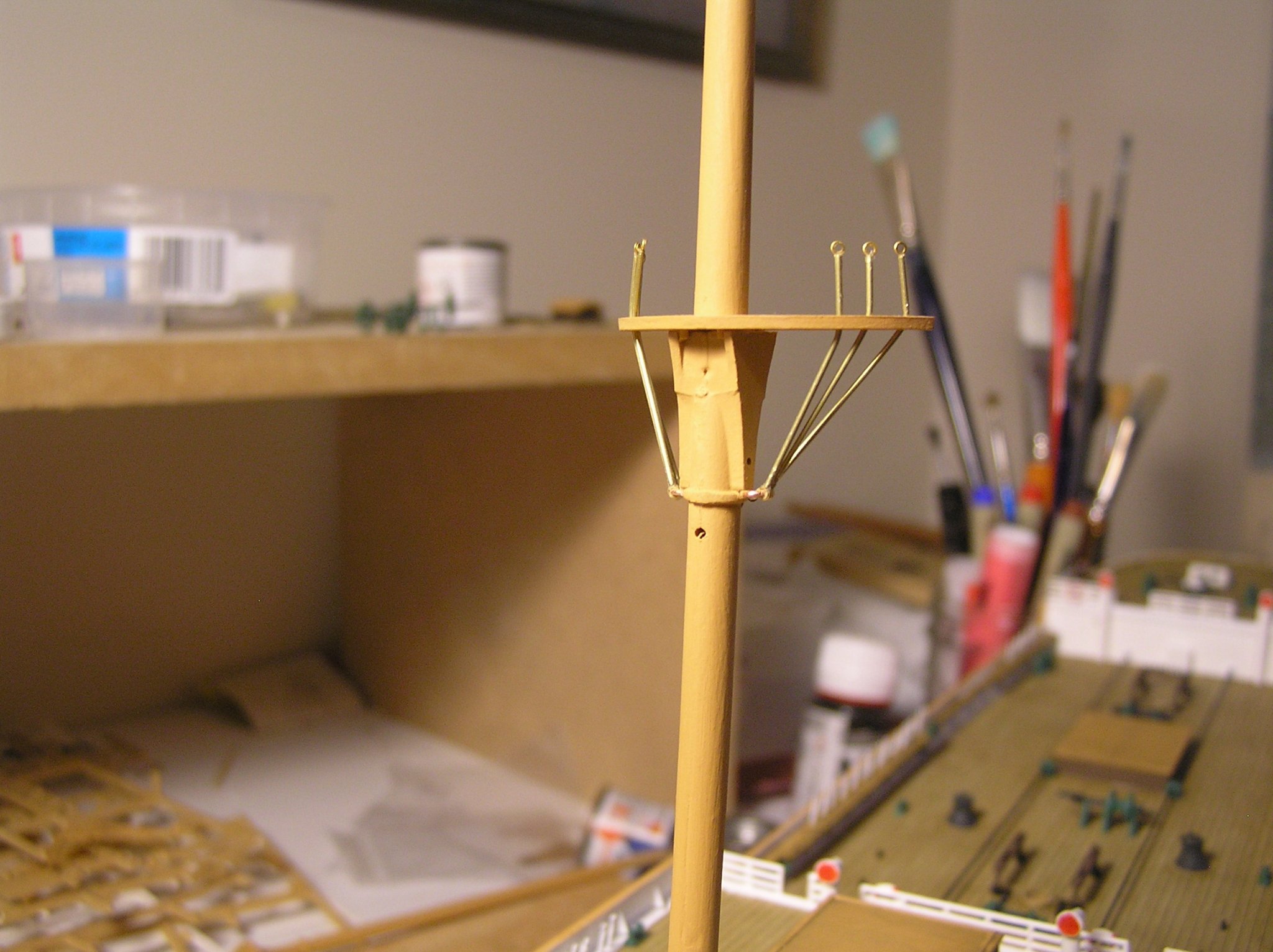
Another little update. I keep thinking of things I could do instead of attempting to solder some brass trusses. Talk about procrastination.
I decided to use the same micro brass tubing and etched eyelets to form the futtocks and linkages for the topmast shrouds. The lower ends of the three futtocks have the same etched brass eyes, through which passes the copper eyebolt cemented into a hole drilled in the mast. I should have decided how to do these earlier; it would have been easier before gluing the copper eyes and/or the mast tops in place, but it worked out because this very small tube is easily cut and not so easily kinked.
Just need to duplicate on the other four masts, and some sort of version for the topmast futtocks and topgallant shrouds. That will burn up another 88 etched eyes I hope I have enough for this model.

- popeye the sailor, Tony Hunt and egkb
-
3


"Peterborough 16" 1:1 Scale Cedar Strip Canoe by Ian_Grant
in Non-ship/categorised builds
Posted · Edited by Ian_Grant
After seeing C Coyle's build log for his 12 footer, I am inspired to post some pictures of my 16 ft Peterborough cedar strip; didn't know we were "allowed" to post non-model builds. I made it from the book "Canoecraft" by Ted Moores, which contains lines for several different canoe designs. I picked the Peterborough as a good type for casual paddling at the cottage, since we already had a 16 ft kevlar Prospector for trips in the back country and his 17 ft "Redbird" design is too long to hang on our garage ceiling without interfering with the opening of the door!
Shout out here for the Canadian Canoe Museum which is located in Peterborough. Haven't been there in a while but they have a great collection.
This canoe was made in the days before digital cameras, but I just this minute took some photos of the old photo album and they seem to have turned out ok. I remember the first day I had my tablesaw out in the driveway, busily ripping six gorgeous 17 ft knot-free western red cedar 1 x 6 planks into 3/4" x 1/4" strips and in doing so creating a monstrous pile of sawdust under the saw as my blade kerf was 1/8" so one third of each plank became sawdust. My neighbour, after watching for a while, came over to ask just what it was I thought I was doing and was amazed to hear I proposed to make a canoe. I then used my router table to cut beads and coves into the strips' edges. When assembling, the strips are tacked to the forms cove side up, making it simple to run glue along inside the cove before pressing in the bead edge of the next strip above.
I thought it would be a great woodworking challenge but making the hull was basically tedium. If you enjoy gluing endless strips, or sanding cedar with its attendant dust, or better yet sanding epoxy resin with even more horrible dust, canoe building is for you! I did enjoy adding the ash trim and making the seats once the hull was completed.
The Peterborough is a good canoe for light paddling. Doesn't have the volume or the high stems for a long canoe trip, and the first time I sat it on my neck with the deep-carved yoke a friend donated the top of my head was pressed against its bottom! Very uncomfortable and not to be portaged...later changed the yoke to a shallower design but never carry it far. It weighs in the 68lb range I would guess, much heavier than our kevlar canoe which is another reason not to trip with it.
Anyway here are a few random shots of various stages. My talented wife painted the West Coast Native loons each side of the bow, taken from an art book we had. God we were young then 🙂
Dust everywhere! Adding the gunwales with fiberglass on exterior sanded, but it looks dull until you wet or varnish it.....
Making the seats which were later laced with leather "bootlace".
The Admiral working on the art, with the hull cleaned but not yet varnished.
Completion shot beside the old townhouse.
First launch; Meech Lake QC.