Ian_Grant
-
Posts
1,652 -
Joined
-
Last visited
Content Type
Profiles
Forums
Gallery
Events
Everything posted by Ian_Grant
-
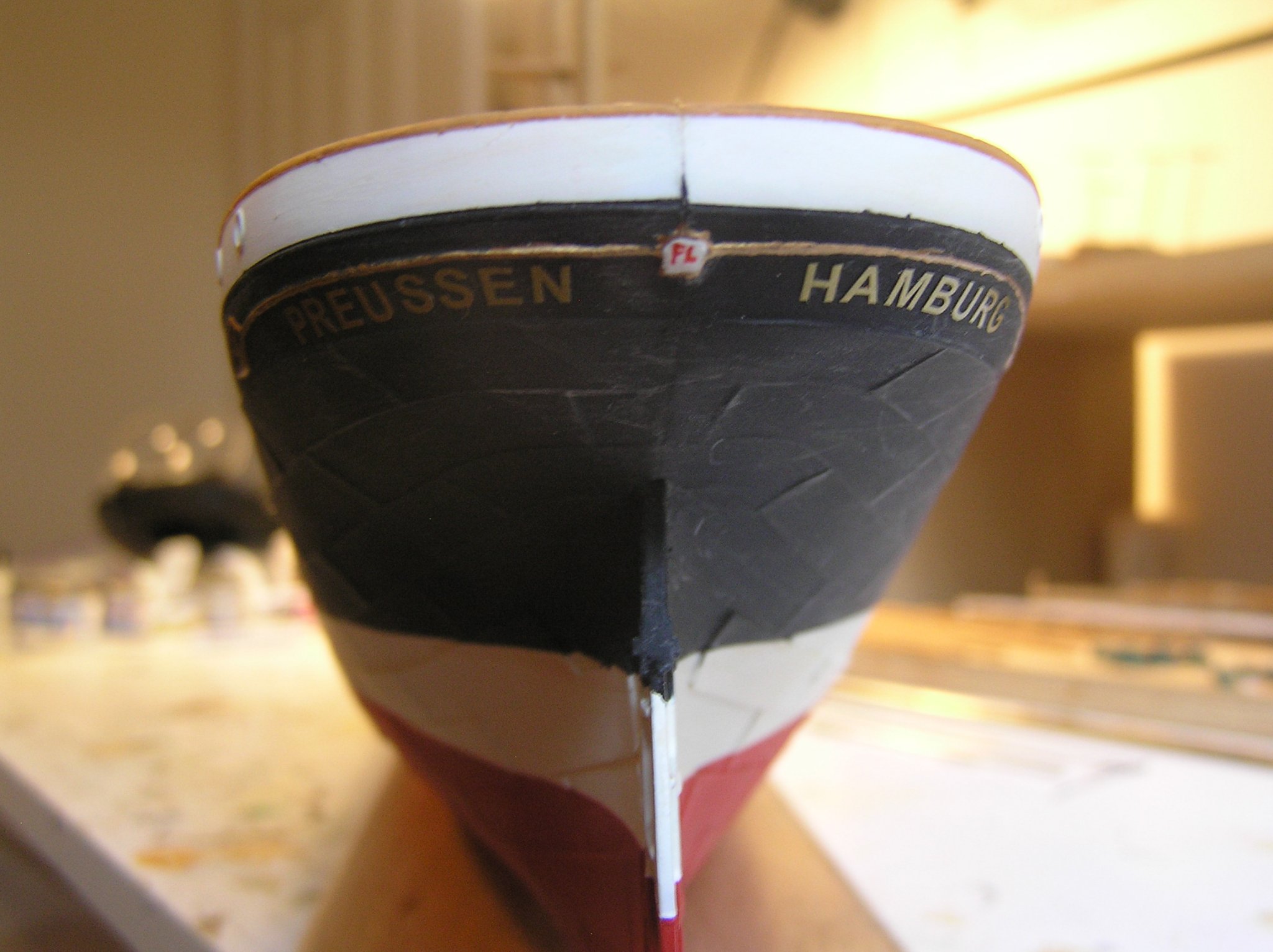
 Still don't know definitively about those rails in front of the pin rails. However, I did come across some nice pictures of Passat's rigging. She does not seem to have the rails. Was also interested to see the shot of the bows, showing the figurehead mostly white with Ferdinand Laeisz's initials in red. Heller instructs to just paint it gold. I may redo it but it would have been easier off the hull. Pictures of bowsprit guys are also helpful since Heller's "instructions" about them are a bit confusing Interesting to see such things as copper domes on navigation light housings, the ship's bell, which Heller does not mention. No evidence of steering cables running along decks but they may have been removed as a tripping hazard; lots of her rigging is omitted too now. I wonder if that's the Heller Passat model cased in the lounge? http://www.jans-sajt.se/contents/Navigation/Galleries/Germany_Passat.htm
 -
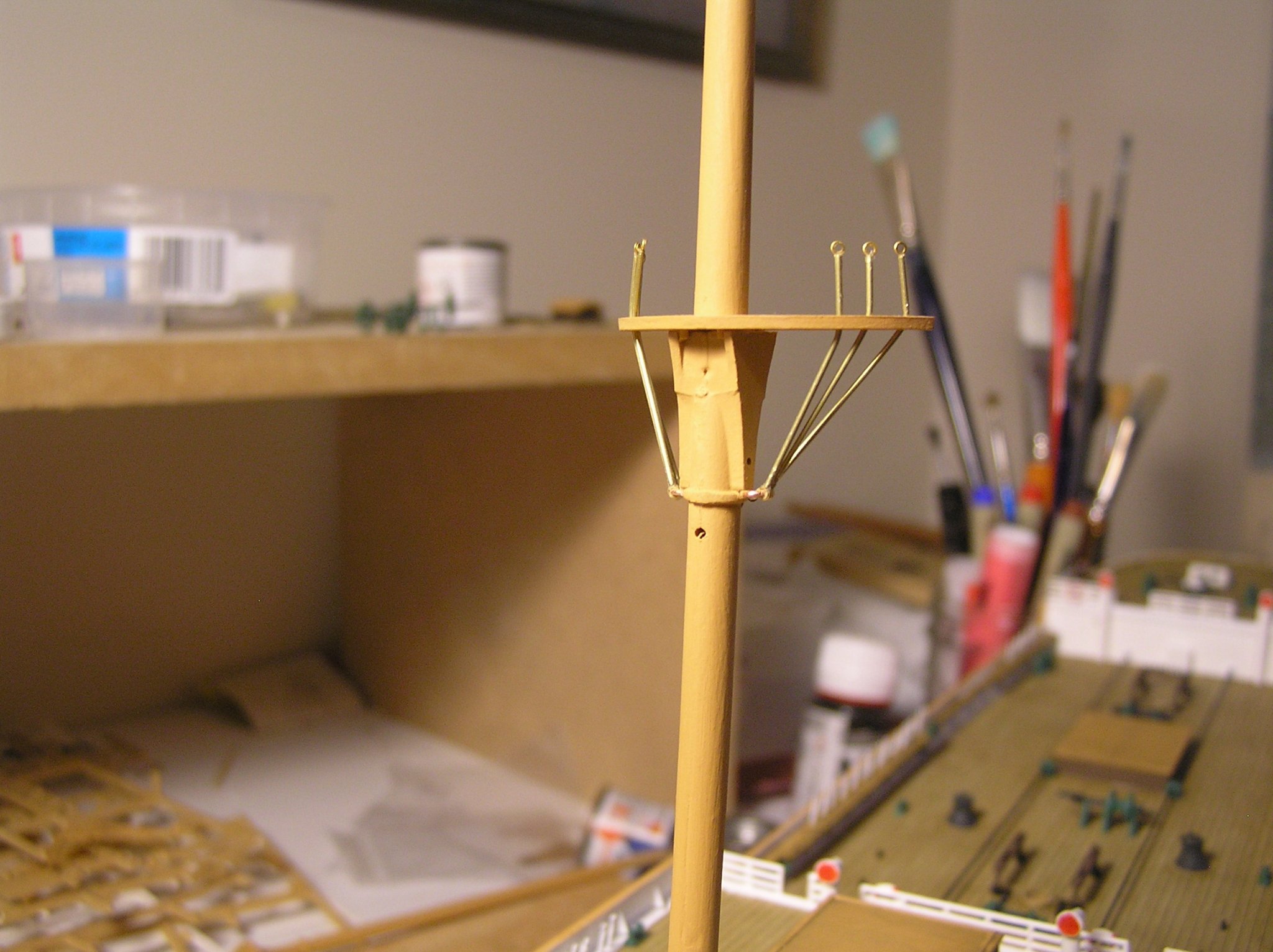
Another little update. I keep thinking of things I could do instead of attempting to solder some brass trusses. Talk about procrastination. I decided to use the same micro brass tubing and etched eyelets to form the futtocks and linkages for the topmast shrouds. The lower ends of the three futtocks have the same etched brass eyes, through which passes the copper eyebolt cemented into a hole drilled in the mast. I should have decided how to do these earlier; it would have been easier before gluing the copper eyes and/or the mast tops in place, but it worked out because this very small tube is easily cut and not so easily kinked. Just need to duplicate on the other four masts, and some sort of version for the topmast futtocks and topgallant shrouds. That will burn up another 88 etched eyes I hope I have enough for this model.

-
For anyone still reading, Heller provides these low metal rails along the deck in front of the pin rail sections where the shrouds and backstays exist, rather like the foot rail on a bar, or so I've heard. According to them ropes come from aloft and pass under these rails then up to their belaying pins. Is this accurate i.e. did these rails exist? I would think it would be hard to belay ropes on the pins with a wall of them going down to the deck just in front. I'll have a look through what books I have on windjammer rigging but if anyone knows definitively that would be great! Thanks, Ian
-
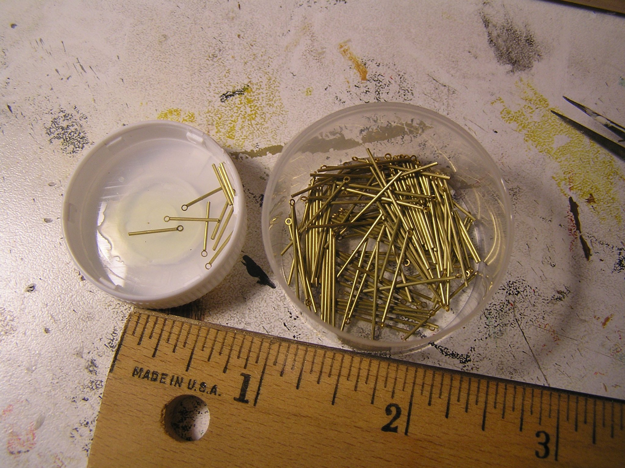
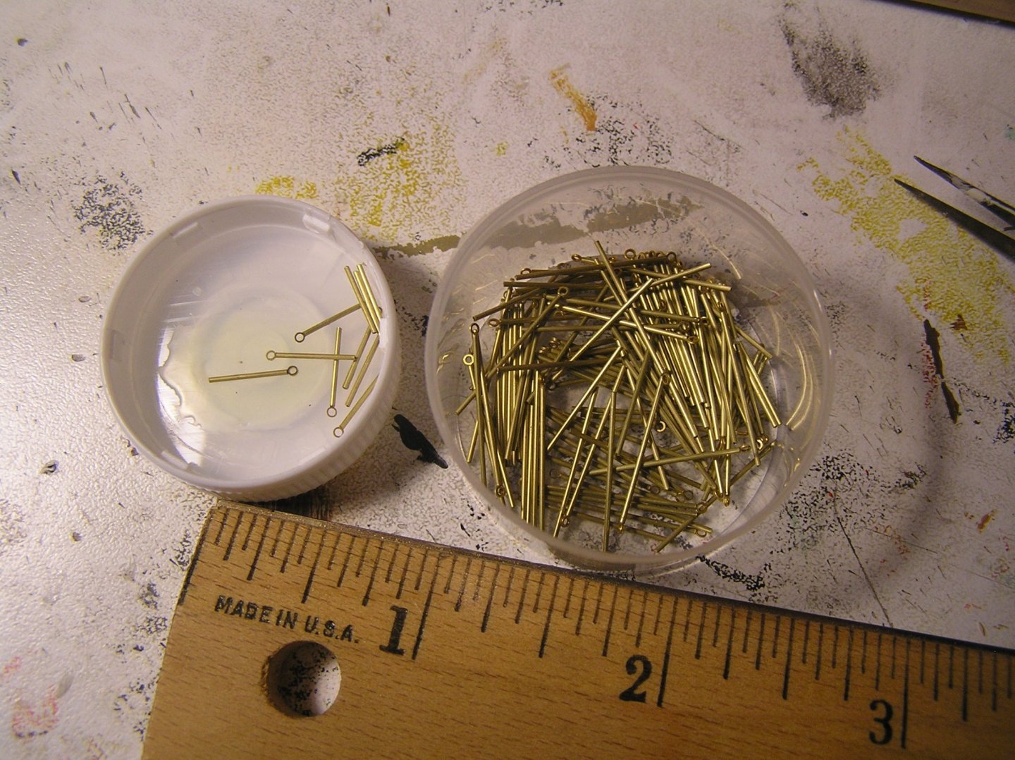
Bill, I just used 0.6mm O.D. micro brass tube, available from Albion Alloys (MBT06). It comes in sets of three ~12" lengths in plastic tubes. Easily cut with an exacto knife. The etched brass eyelets are glued in to the ends. Available from various model suppliers, for example: https://www.model-dockyard.com/acatalog/Caldercraft_Period_Eyepins.html These eyes are immensely useful, for example I cut all those nubbies off the bowsprit and replaced with some of these eyes glued into drilled holes. I also used many to form the mast stay attachment points at caps etc. Note too the copper eyelets listed below the etched brass at M.D.; they can come in handy too and are almost exactly the same size as the plastic eyebolts supplied with Heller models like Victory, Soleil Royale, and our current efforts. Useful to avoid a plastic eye breaking as you are rigging!
-
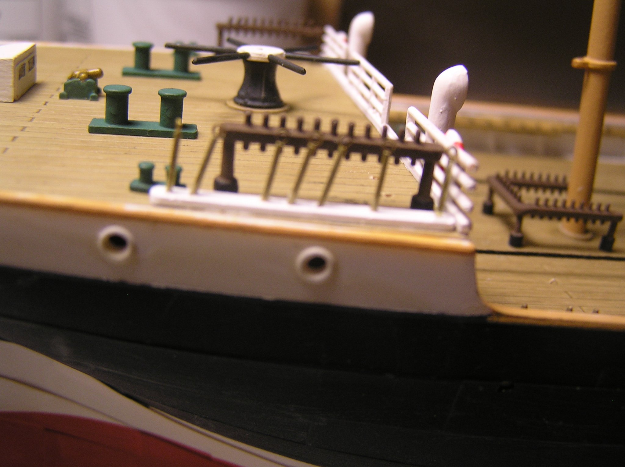
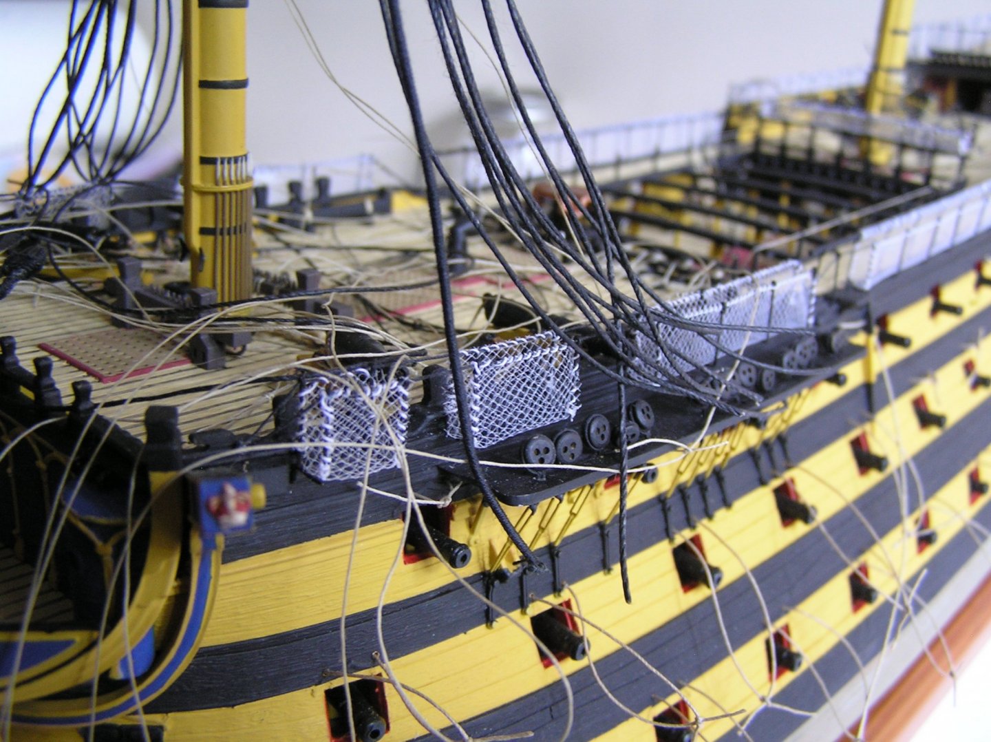
A quick update - I finished the 146 renditions of rigging screws for shrouds and backstays. This photo shows what they look like, passing down to the deck inside the bulwarks. A big improvement, I think, on Heller's suggested small loops of thread passed through the pinrail holes with knots trapped underneath. I'm getting close to some serious rigging. Just need to form brass yard trusses somehow and oh,... figure out what thread to use. I have three sizes of chain too with probable need to order more of whichever I choose. Probably the 42 link/inch at this scale.
-
Bill, I already did but no reply yet. Maybe they're in a Covid shutdown. Maybe they just whisked a part into the mail without bothering to reply. I don't know. My French isn't up to phoning them. Since it is the stern railing, and accessible at any time, I suppose I can wait.
-
It's taking less time than I thought to produce my "shroud turnbuckles". Tedious though. Cut 146 short lengths of 0.6mm OD brass tube and glued an etched brass eyelet into one end of each. There are two lengths - the shorter for the bridge and poop decks where they attach right to deck level, the longer for those which pass through a well deck pin rail and thence to deck. Photo below after most of the shorter ones are glued in. For the poop deck I added small strips of white-painted evergreen over Heller's original holes in the deck, because the tubing is undersized for the holes and I didn't want a glue mess flowing onto my deck. Photo below shows starboard side, unfortunately out of focus as my old camera couldn't zoom in well. You can see the brass with eyes, all at odd angles since they ascend to different locations up the jigger mast. I'll be painting them white. The ones on the bridge deck are secured and painted first coat of white. Again, sorry for the focus. I had a little trouble setting them all at the same height while wearing my headband magnifier. Again, all at individual angles which I set roughly by eye but I will be be bending them later which should not be a problem with these tiny tubes.

-
Bill, that's a great idea! I will try to contact them about it although I only know the part number in the Preussen kit. I was thinking of asking my brother if he could 3-D print one for me; not sure of the capabilities of his printer, resolution-wise. I was also going to ask him about making me some "iron" sheet blocks......... Thanks again for your help! Looking forward to your "Potosi" log..... Best Regards, Ian
-
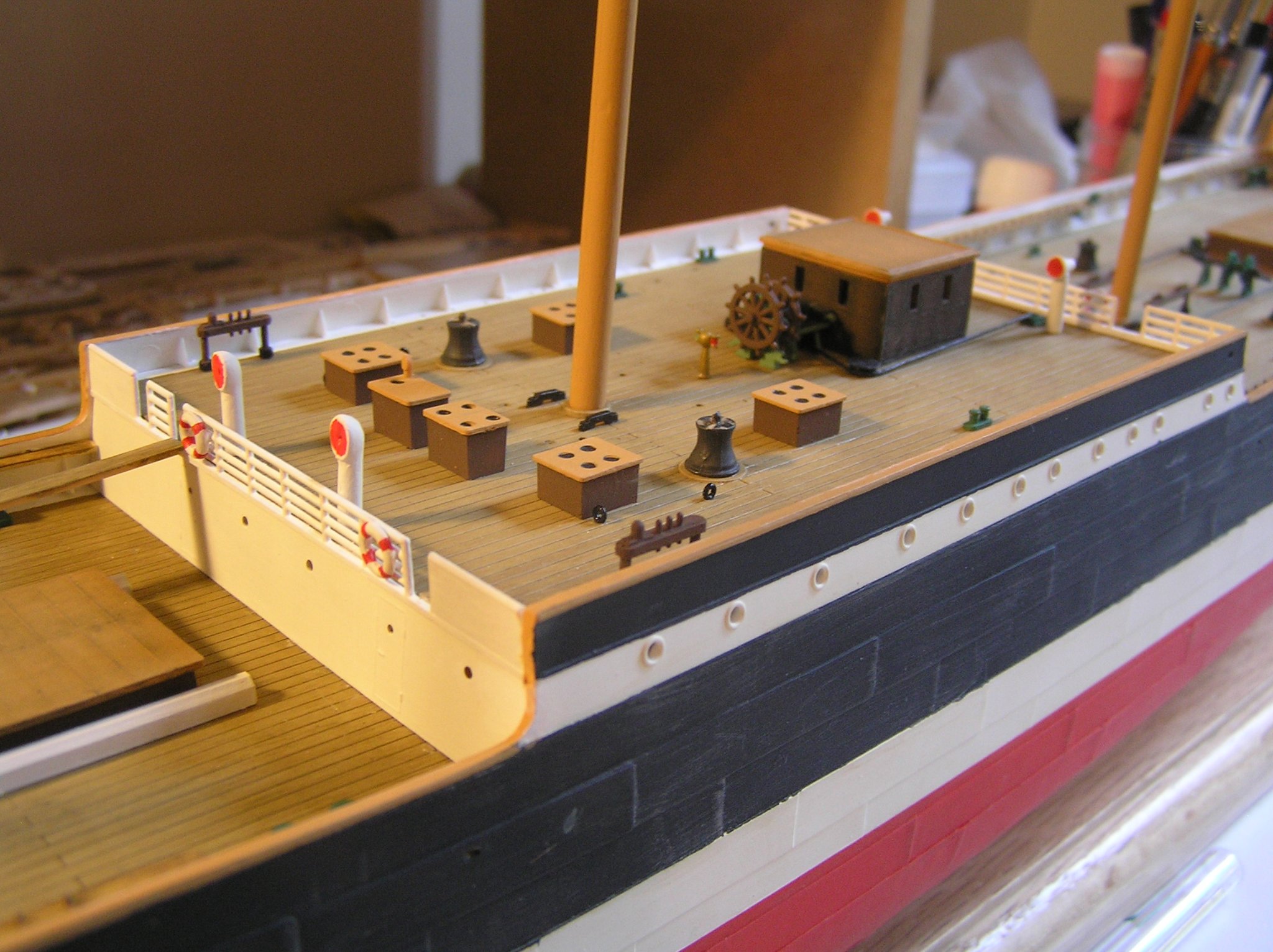
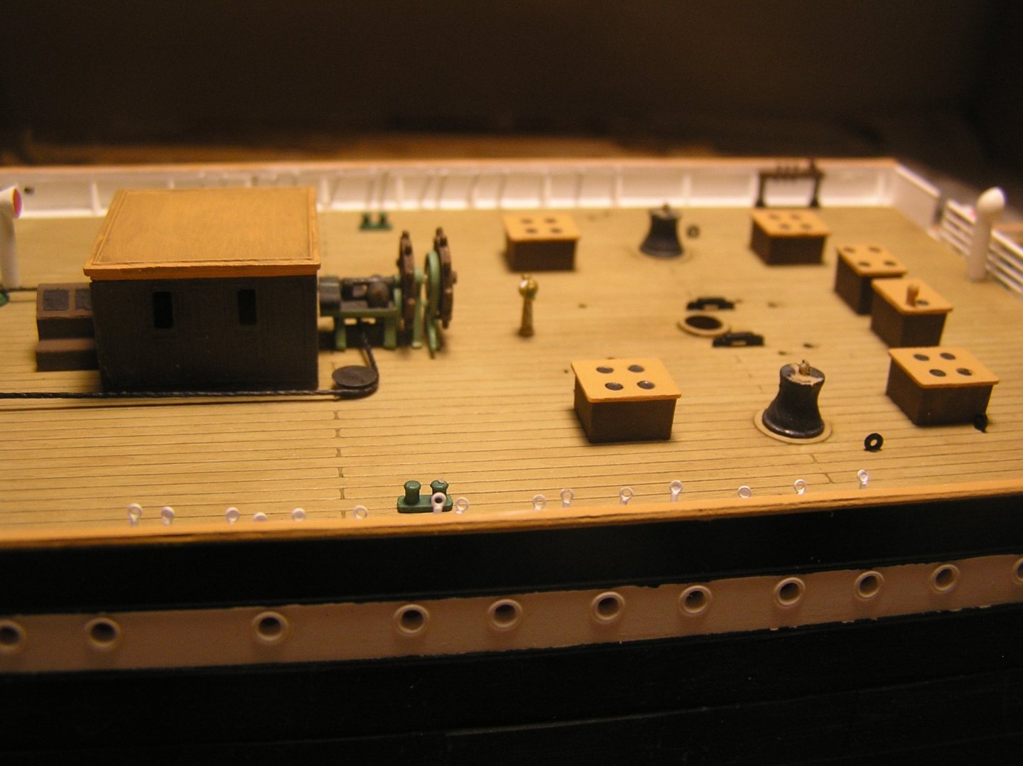
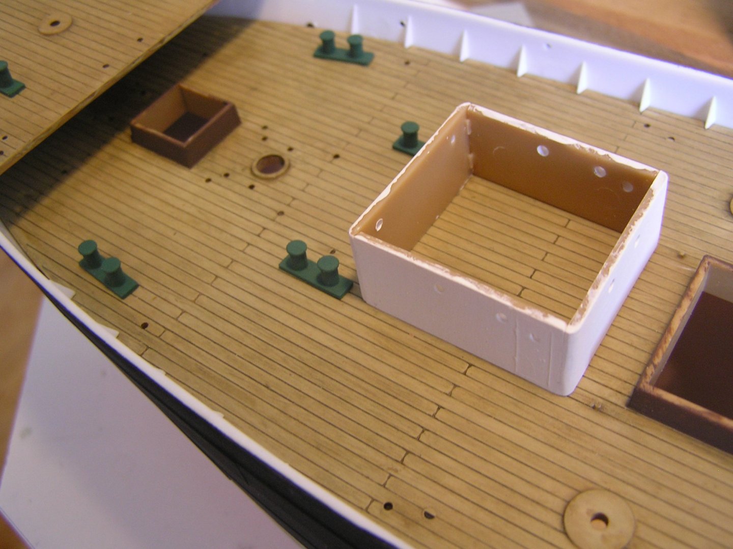
Bill, thanks for your kind words and encouragement. I remember reading a thread, probably somewhere in model ship world, where the author advocated buying a "Cap Horn" (less popular and apparently much cheaper than Preussen on ebay or whatever) and simply converting the jigger mast to square rig and hey presto! - a Preussen. I was aware of Potosi but I thought it was the only 5M barque ever in the grain/nitrate fleets. Apparently as a barque much more manageable than Preussen. Since you have Cap Horn, perhaps you can help me on something. The photo below shows an auxiliary bridge attached to the after storm gangway. The square hole accommodates a ladder up from the after well deck. The central hole is for a second binnacle. Holes near the edges are for stanchions. Do you have any idea what those bucket-like objects along the two sides, outside of the railing, could be? One final comment: my model kit arrived with the curved stern railing twisted and broken. Broken I could patch, but twisted would be impossible to glue onto the stern properly. I figured if I could heat the plastic to soften it I might be able to undo the twist. Well I put it in hot water (I recall some of my old lego blocks getting distorted when I used to take "submarines" I had made into the tub with me). I put the railing in a pot on the stove. I kept pulling it out and it was never getting malleable then suddenly it just collapsed and melted/distorted. I sent a message to the Heller website for a part replacement but I have heard nothing. Anyone - does Heller still exist? Is there somewhere I can get a replacement part? Thanks, Ian
-
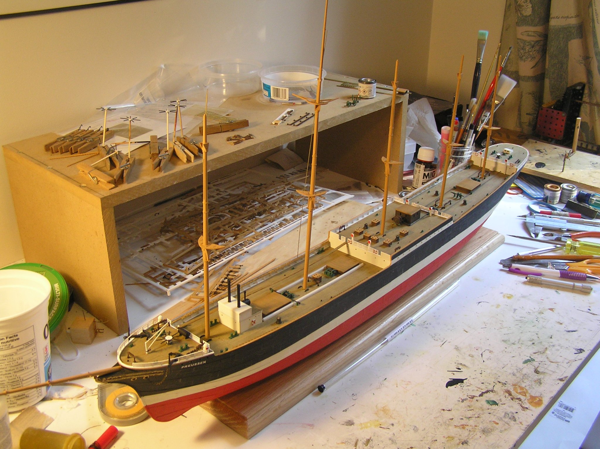
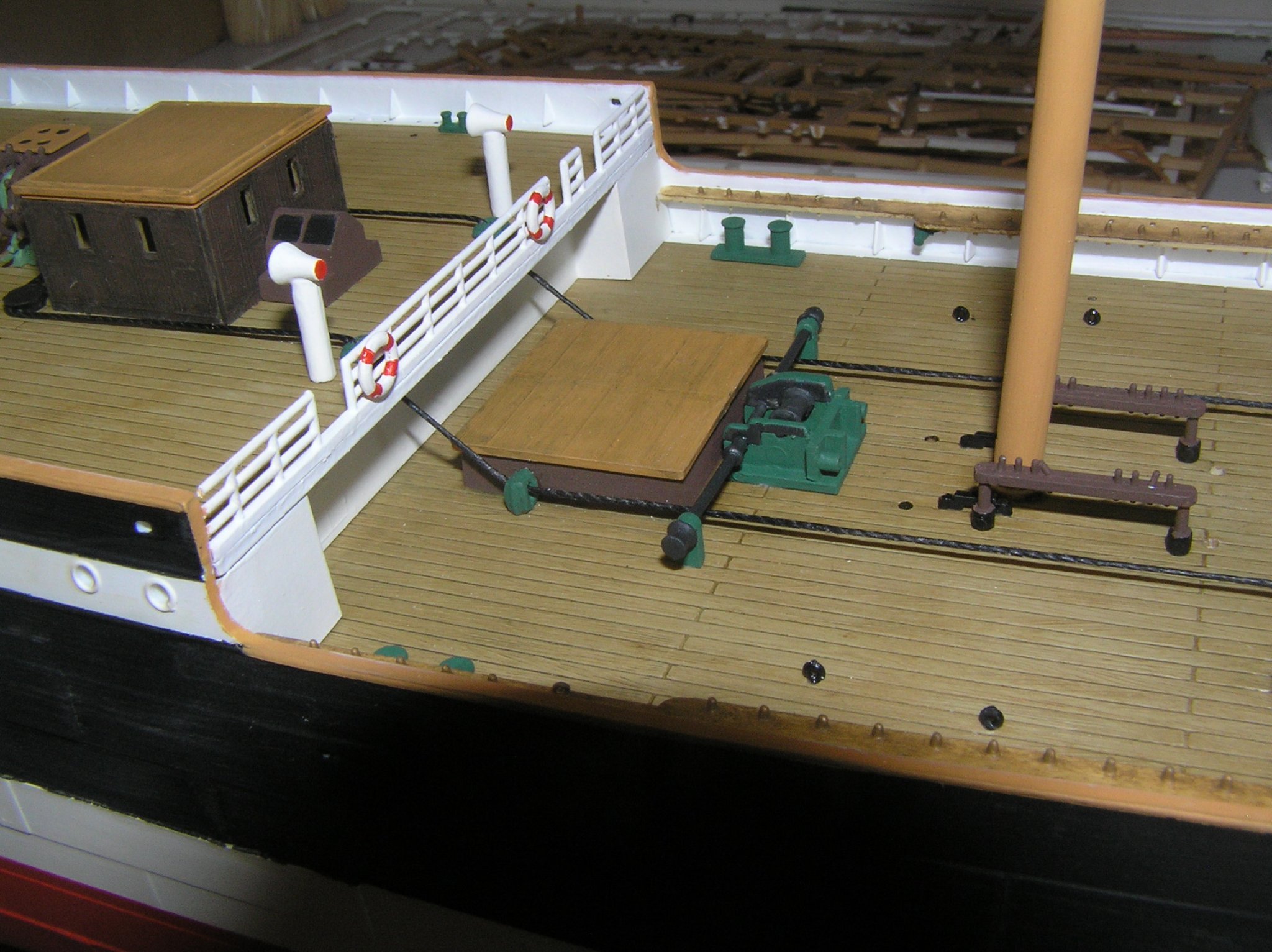
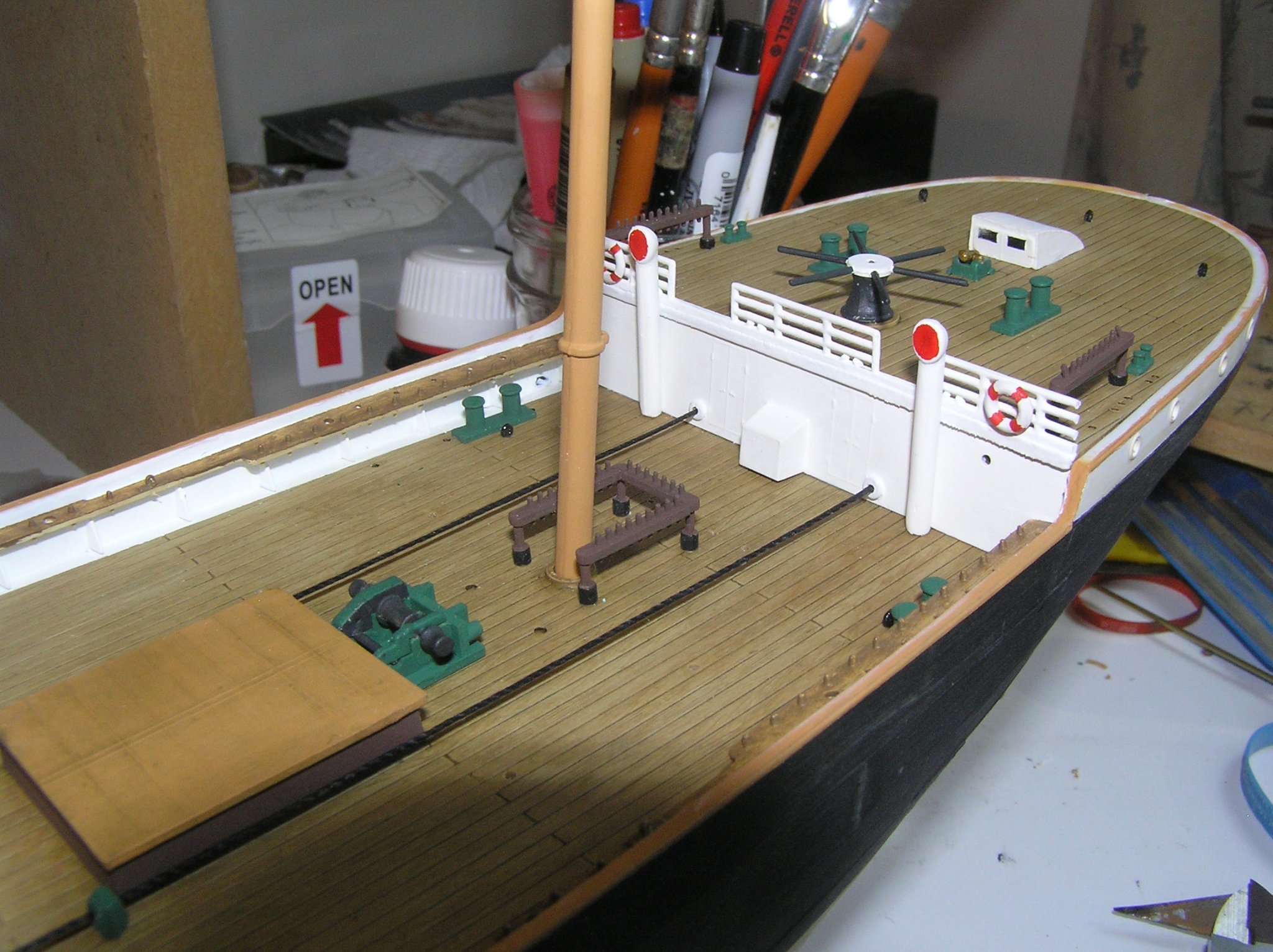
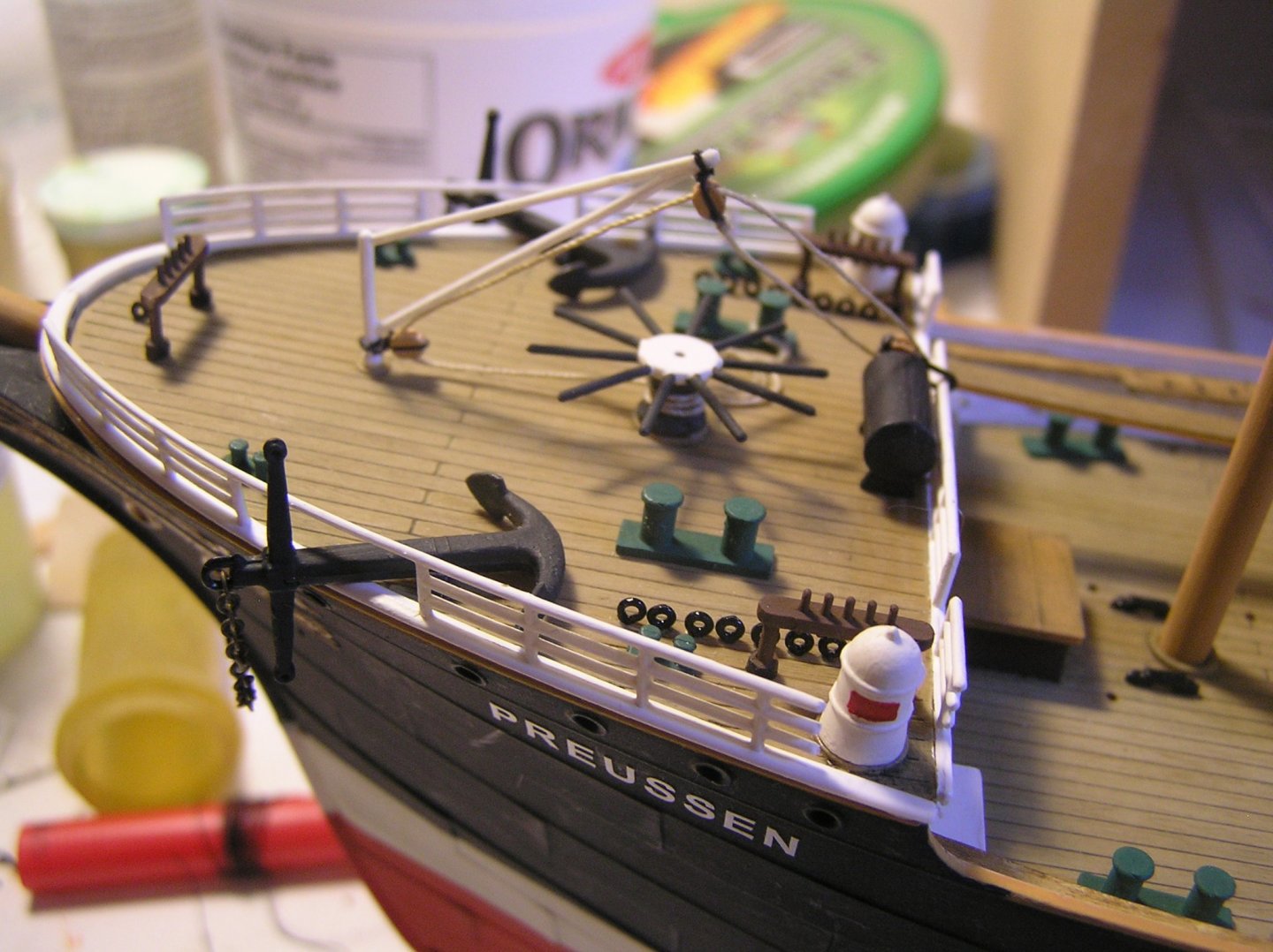
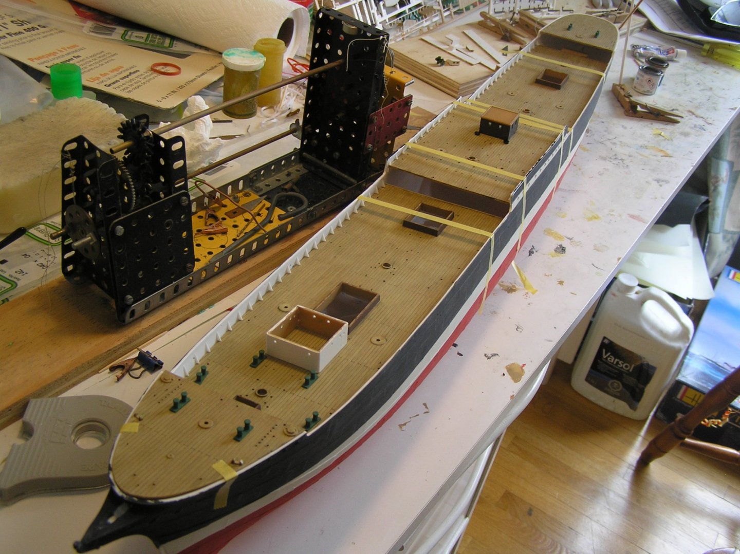
Let's see, where was I?.......I have the bulwark pin rails attached and painted in the well decks. Here is the model with the lower parts of all five masts dropped in. I spent some time making notes about all the attachment points for mast stays...again....and I need to add yet more eyes for them at the lower and topmast caps. I dry attached the main topgallant mast to check the angles of some of the stays using a brass tube. I plan to cut these brass tubes into short lengths and glue in an etched eyelet to form rudimentary "turnbuckles", if rather one-ended. They'll pass through the pin rails and into holes drilled in the deck to emulate the attachments to hull plating not just bulwarks. For the pictures, I sat the top of the boiler house, which includes part of the forward storm gangway, in place. I actually added a piece of rigging, finally, on the anchor crane. Round the capstan three turns and coiled onto a bollard. I just stuck the hook on the railing. The shiny eyebolts will get some matt varnish later. Thanks to Marten's advice I also rigged the steering cables. I formed some guides from old Revell plastic blocks. I filed one face off a pair to form the guides at the rear of the bridge deck. Another two pairs were filed slightly shorter and attached to the after well deck using short lengths of brass rod. The steering cables pass through the after bulkhead. Here is the lettering at the stern. I added Ferdinand Laeisz's initials on the small shield at the centre for lack of a better idea. That's about it for now. I'll check in again when I have the "turnbuckles" completed. This could be a while; I'm busy working jobs and there are 146 shrouds and backstays on this ship.


-
I admit it's a while since I posted, but the Canadian summer is too short also people finally became comfortable with having me in their home to renovate as long as I wear a mask. When not working, the cottage beckons: swimming, sailing my dinghy, biking, canoeing, wine, rye and ginger......... I have made some progress and I did get the new camera battery. More coming soon........
-
I hope you get one rkwz! If you buy all of Daniel's etch sheets you will have a museum quality build. Just be sure to obtain a copy of "Anatomy of Nelson's Ships" by Longridge in order to rig properly.
-
Dear B.E. --- Thank you so much for taking the time to reassure me on the mizzen gaff!!! On my model the throat lies just above the blocks for the davit lifts, as it does in your photos. So that's great. I found when trying to set the angle of the gaff that the limiting factor was the aftermost catharpin, as opposed to the mizzen top. Even in Geoff Hunt's painting the gaff peak lies significantly higher than mine. Now I'm wondering if I set the mizzen futtock staves too low; I made them equivalent to the length of the doubling as for the other masts. I don't need to think long and hard about changing the futtock shrouds - no way, no how! Thank you again!
-
Alas! I have come to realize that my driver gaff is stepped too low on the mizzen mast! I recall at the time looking at pictures of how high the gaff peak reached compared to the mizzen topmast and wondering why mine could not go that high - I operated under the assumption that the gaff throat must be below the mizzen catharpins, in order for the gaff to be lowered if necessary. Now I think that it was stepped above the catharpins, just below the cro'jack yard and remained there when at sea unless damaged. If necessary the catharpin lashings could easily be cut to allow the gaff to be lowered temporarily. Fixing this would mean re-rigging the mizzen topgallant braces, the gaff peak and throat halyards, the gaff vangs, and more especially the gaff parral beads. It's easy to say but not very accessible to say the least; yet now that I've seen it I can't unsee it. What to do, what to do??
-
Very nice! Love the sails - how did you get the sail artwork to be so crisp on the cloth?
-
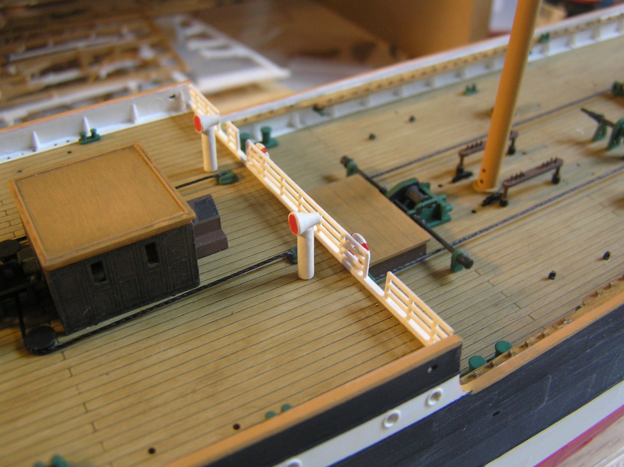
Hi Bill, my guess is these are water butts for the crew, up high out of the seas washing through the waist. (Sorry I couldn't figure out how to do one of those "quotes" so I just cut and pasted from your earlier post): "......Something I am curious about and someone may know. On the deck house in the back there are two elements that look like upside down baskets near the front. No idea what they are..........."
-
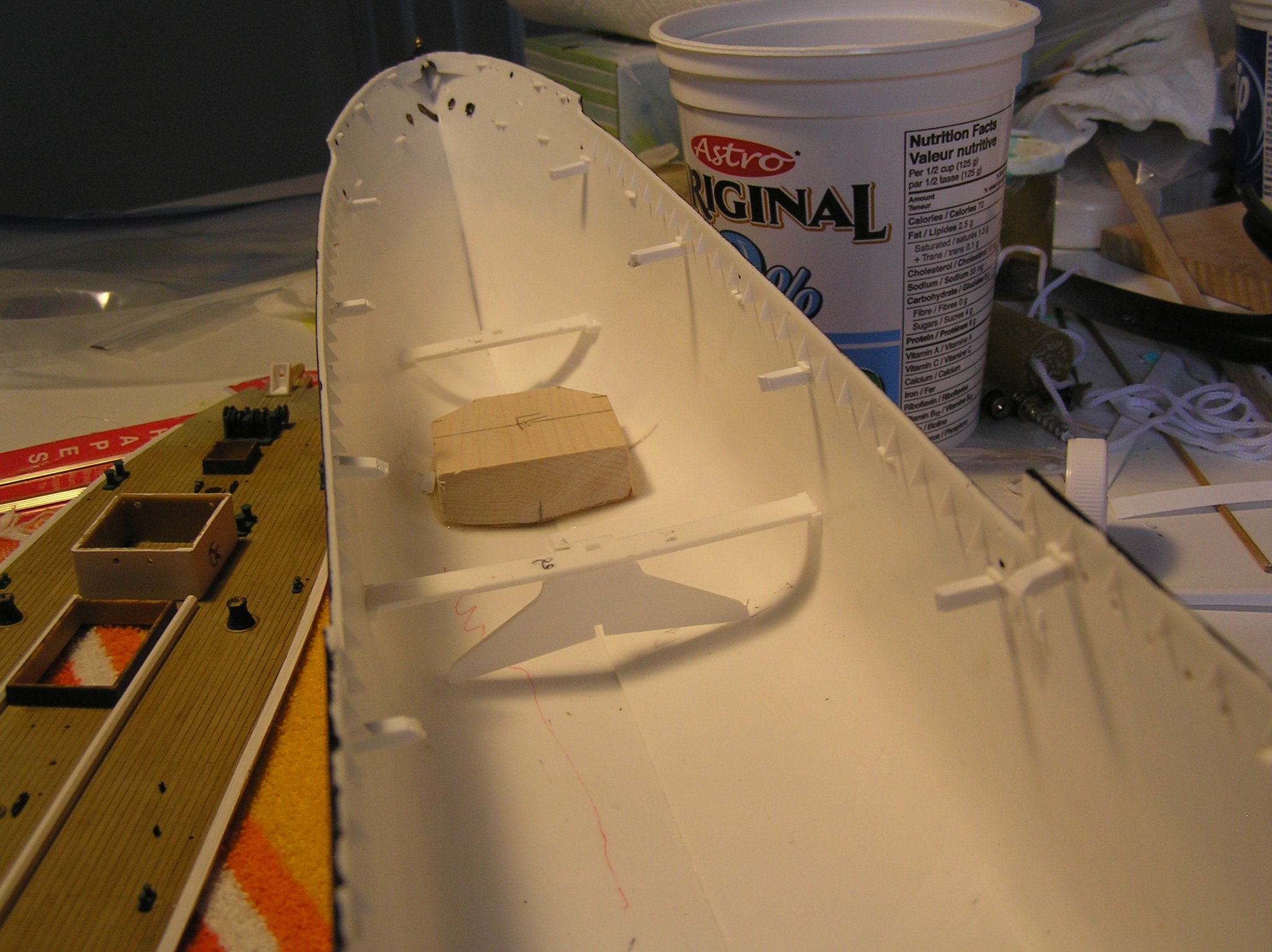
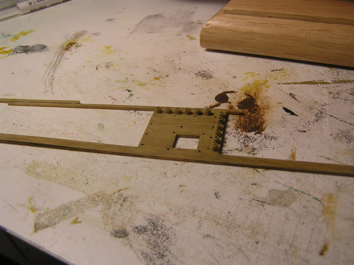
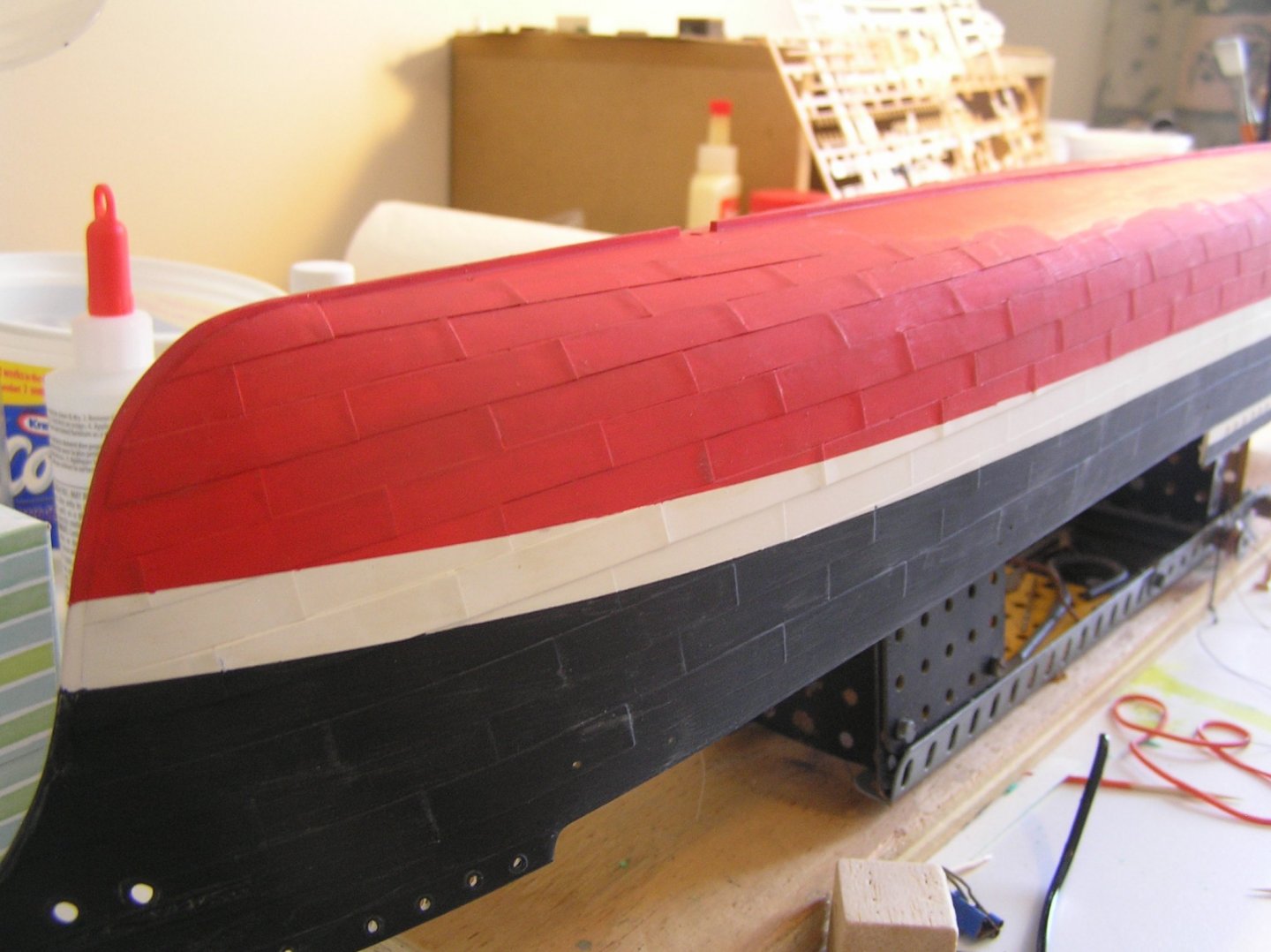
Hi Marten - Yes I understood you were joking about the 21 strands LOL 🙂 Couldn't find an english version of your magnificently titled German tome on "Preussen", but I did come across "Last of the Wind Ships" by Alan Villiers featuring many many photos aboard large windjammers so I ordered a copy out of interest. Here are a couple more photos of the build. Unfortunately the Li battery for my old camera is on its last legs - now a single flash photo per charge cycle!! - so pictures are limited. I've ordered a new battery. This shows the evergreen stubs I added to prevent the well deck from falling into the hull when mounting. You can also see a wood mounting block for the stand, and the re-purposed part for the supplied stand acting as a support for the rather flimsy mast step My lettering arrived and looks great. There's more in gold on the stern but a picture will have to wait. Next steps are to add the forecastle railings and anchors. Then I will reeve the steering cables as you explained (thanks again) before adding the final deck at the poop. EDIT: Doh! Just noticed the gold letter "N" fell off! Will replace and this time brush over with matt varnish. Speaking of varnish, my old can was a little gummy and tinted; the whitish marks you see all over the black are brush strokes. Any touching of the hull shows up starkly on the black portion. Will another coat with a nice new can of varnish conceal this mess? I could always pass it off as salt stains 😉 I also painted the #63 colour on the bulwark rails. A fiddly job when four coats are needed for coverage. Some touch-ups required. Next I will paint the matte white on the lower part of the inner bulwarks (just below the pin rails) then glue the pin rails in solidly with model glue with no paint intervening, then paint the pin rails and bulwark sides above them. It's looking nice with railings being added. Will replace this blurred photo later. I ran into a problem with the ladders, specifically, the ends are mitered in the wrong direction so if you have the nicely molded steps on the visible side then the bottoms are teetering on just the miter points. If you orient the miters flat against the deck and bulkheads then the rather ugly what-was-meant-to-be-the-back-side-of-the-ladder is visible. Not sure how to fix this; would be awfully fiddly trying to add little pieces at four ends of nine ladders. Buy after market? A second annoying problem is the two pumps. Each is set just aft of a mast, and the mast's bitts enclose both the mast and pump with no belaying pins on the portion of the bitts beside the pump handles. I noticed that the pump shafts touched the bitts before the pump touched the deck. I added tiny slivers of evergreen to make it touch the deck. But now I noticed in a test fit that the pump interferes with the stays running from cleats at the mast foot to the next mast aft. What- really?! You'll notice I have yet to add a single piece of rigging. Once I have the well deck pin rails installed, I will have to manufacture about 160 "turnbuckles" for the shrouds and backstays from micro brass tube and etched eyelets. Then the rigging work can begin. I improved the bowsprit considerably by cutting off all the chunky-looking plastic "cleats" to tie on martingales, shrouds, foremast stays etc and adding etched eyelets in small drilled holes. That was another thing betraying the age of this kit. Unfortunately I forgot to take a "before" photo but it was mighty clumsy looking. Also, the supplied martingale was a flimsy little thing, which was to be butt-glued to the bowsprit. Yeah, that'll hold! I made a martingale from micro brass tube with an etched eyelet in the bottom end, and glued it into a hole drilled in the bowsprit.


-
Nice looking kit. Good job on the planking. I bought a Billings Wasa in the 70's as a teenager. It too was single-planked, with cheap printed decks including hatches, far less nice than yours, and what did I know about it anyway? My planking was so-so. I remember cursing trying to pin them into the balsa blocks at the bow. There was no internet then with advice and examples. When I got to the point where the next step was "Use the two balsa blocks provided to carve two lions" I decided I was out of my league. I threw the hull out years ago but I STILL have the fittings kit! I've never dared try another wooden kit, although I did make several RC kits and a couple of scratch builds. Then off to University and never touched a ship model for 35+ years. Looking forward to seeing your progress!
-
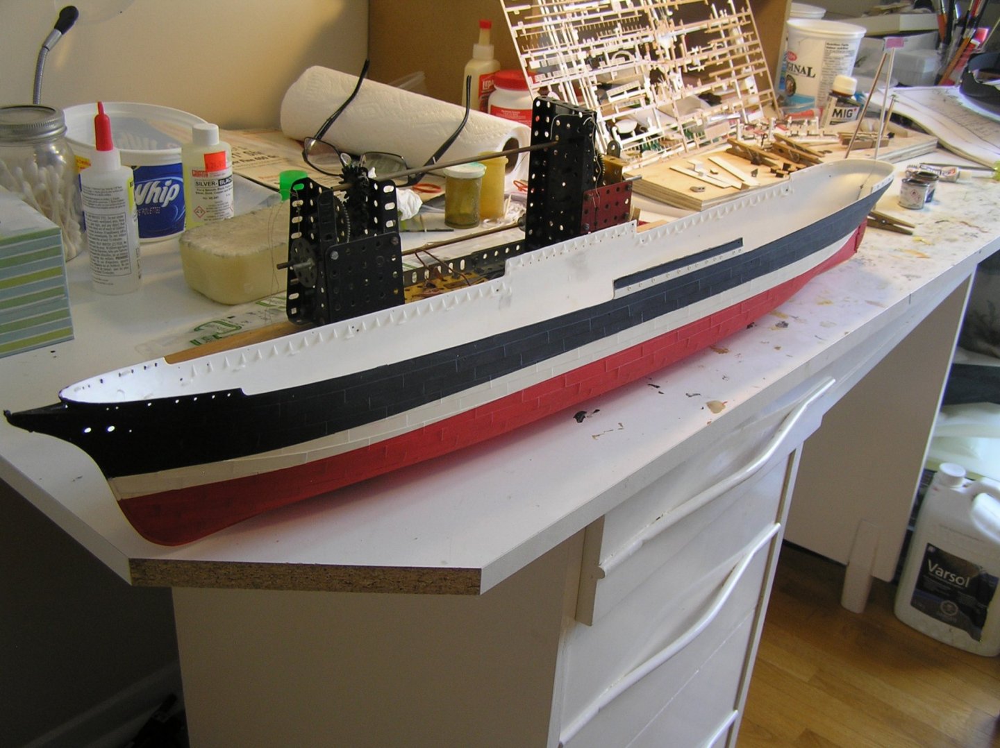
Yes, my hull halves were both twisted from being crammed across the box diagonal. If you held the stem and keel together, they both flared out at the stern. If you clamped the stem and stern, then the keel flared apart mid-hull. And it is a very small keel to clamp onto. This long-ish hull is made of very thin plastic, far thinner than the reassuringly thick and solid hulls of "Victory" and "Soleil Royale", and there are very few alignment pins to help you. If you sight along the keel line of each half, the thin plastic ripples up and down a bit as opposed to being a straight line. I decided on a multi-step gluing process. First I glued the stem and 2-3" of keel. After that dried, I glued the stern and 2-3" of keel. When that was dry, with the ends fixed, it was relatively easy to glue the remaining keel, aligning as I went, and clamp with small paper clamps. I added some wood inside to straighten the keel; a bit tricky when there are five mast steps inside the hull. After gluing, when I dry-fitted the forward well deck it did not align properly with both hull sides - there are little molded-in vertical "stops" in the hulls to locate the midship end of the deck, as well as the horizontal support tabs. There was about a 1/8" offset(!), which could be corrected by twisting the hull slightly. When gluing I sat and held the hull securely with the deck aligned until the glue set up. Same observation and procedure with the after well deck. Even the bridge deck required some hull flexing to align! But in the end it all turned out, although I'm not absolutely convinced that there isn't a very slight remaining hull twist. Hard to tell by eye. A final note on adding the bridge and well decks: there are small "ledges" provided inside the hull to locate the bottom face of the decking, but they stick out LESS than the molded triangular "webs" reinforcing the bulwarks above deck level. So every time you press the deck past the bulwark webs, it falls into the hull past the ledges!! VERY frustrating! I added a few bits of evergreen projecting further out, below the decks, and it became child's play to slide the well decks in from midships due to their taper. This also avoided smearing model glue on the bulwarks.
-
I try to avoid gluing painted parts, but if needs must I use cyano glue on painted parts.
-
Cable-laid....21 strands....0.5mm scaled diameter....got it! Thank you very much Marten! So I need to make little rollers where the slots are, then the wires pass over the rollers, angle through the railing down to the after well deck, run along this deck on say two more pairs of rollers, then (a) disappear through openings in the poop bulkhead? (b) pass through more rollers to go up to the poop deck then go down through this deck? I've seen such tiller lines on other build logs but didn't realize they would be routed like this on such a big ship. Do you have a reference book detailing things like this on the big windjammers....I'd like to buy a copy. Thanks again, Ian.
-
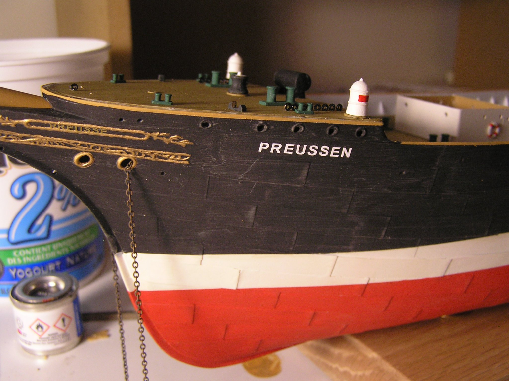
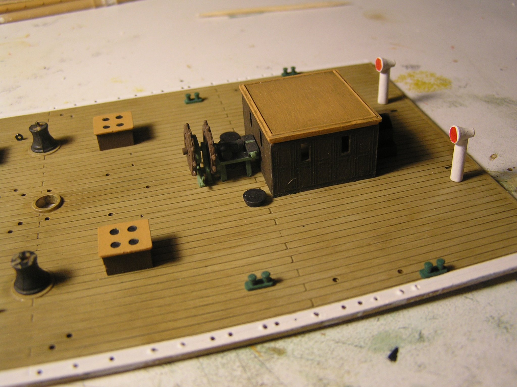
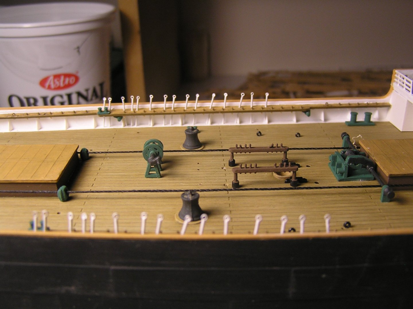
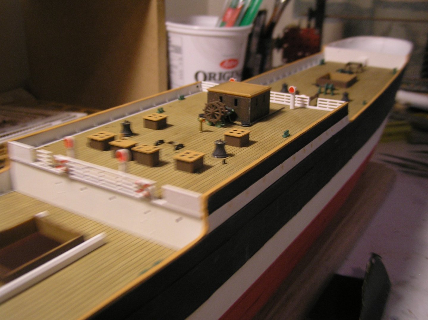
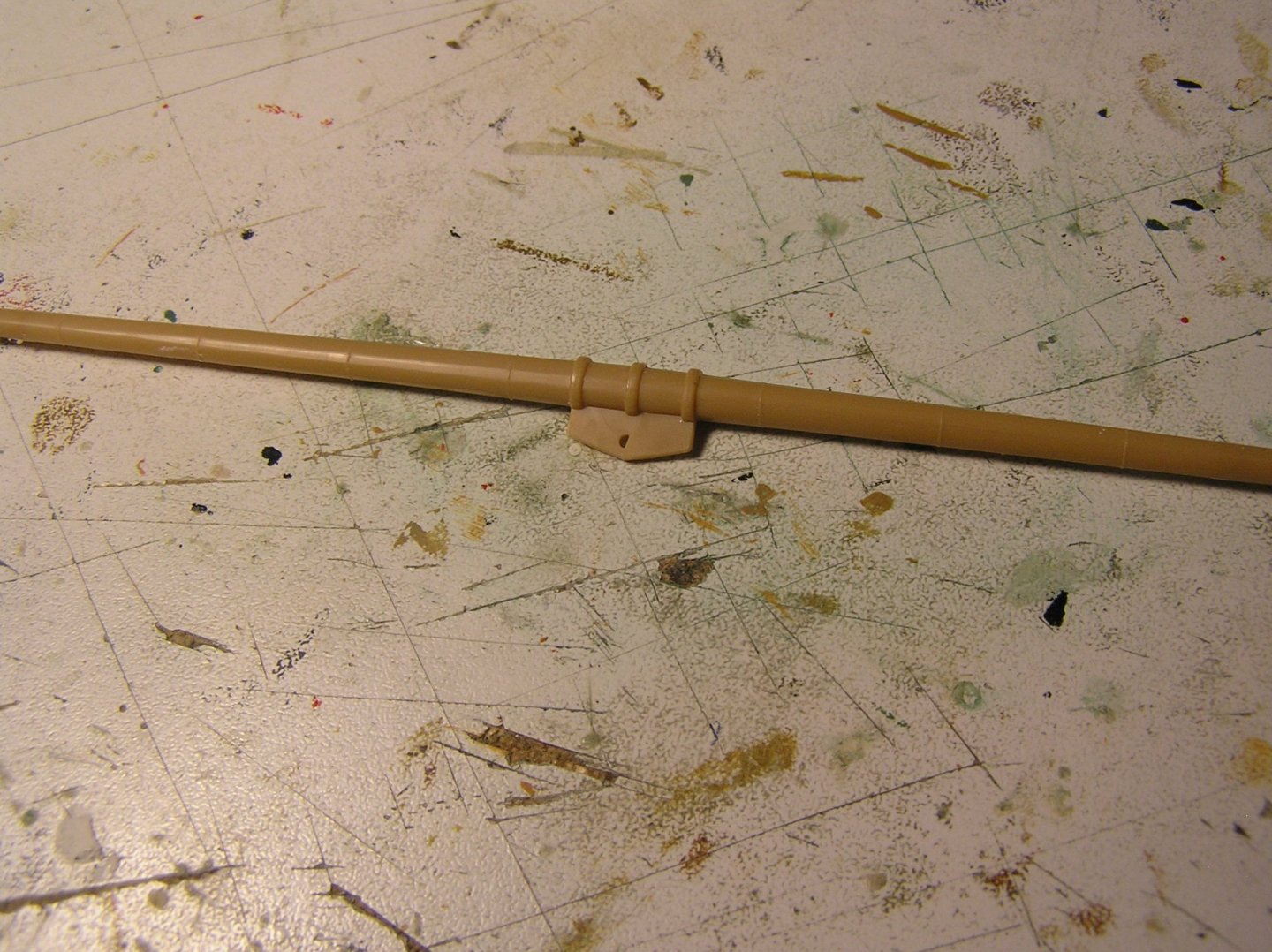
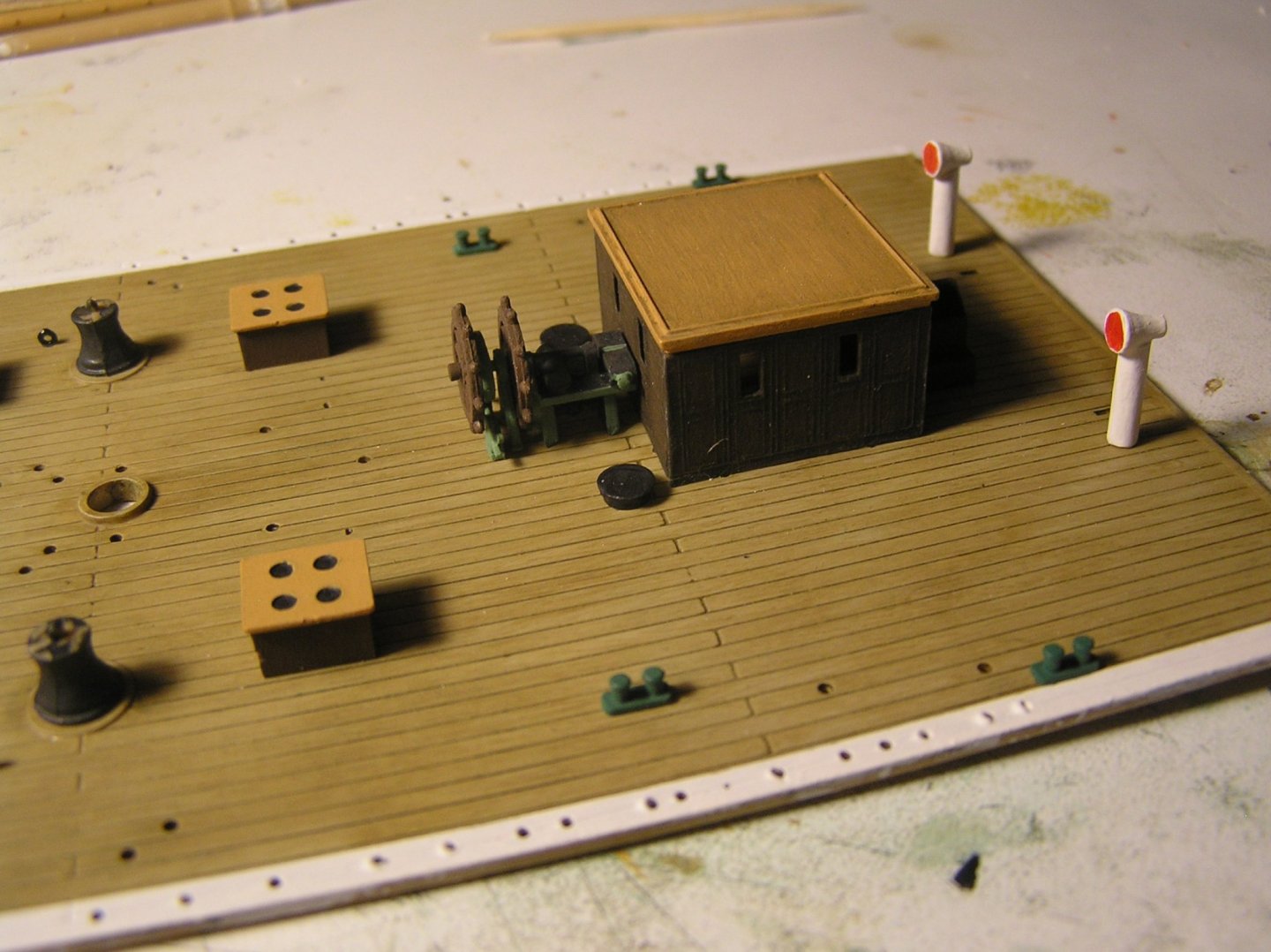
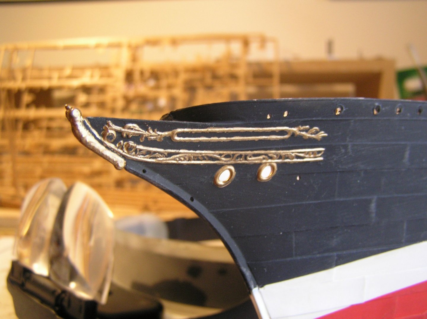
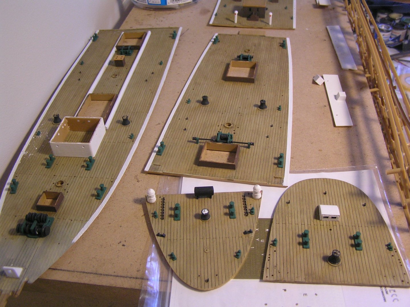
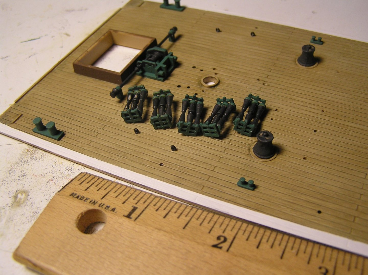
Dear Yankovitch: Not to worry, this log will continue until the bitter end. I tend to go a while between entries as opposed to reporting daily details. I worked for a time on painting deck machinery. The instructions say to just cover all winches, bollards, capstans, and cleats etc with matte gunmetal grey, but that sounded awfully drab for the pride of the Laeisz fleet. Instead I painted the machine "frames" the same green that I used on the bollards, and used tank grey on the "innards", just to accent them. Here's a picture of the wheel just in front of the chart house on the midship bridge deck. Incidentally, I wondered what those black round things were at the corners of the house until I noticed a line drawn in the instructions, with no reference. I realized the steering lines from the ships wheel pass round these swivels then go down through the deck in the slots just beside the aft ventilators. Does anyone know if that would be cable, or chain? Thanks in advance. Here are all the decks at the moment. As I mentioned in an earlier post I decided to paint a white "waterway" at the edges of those decks confined by bulwarks to make painting inside those bulwarks easier after I glue in the decks. Capstan barrels are all glued in but not yet the heads with bars because they're fragile. Of particular interest to me are the Jarvis triple brace winches. The photo below shows Heller's rendition of the full set of five beside one of the cargo winches. Each of these 1/2"x1/4" machines has three pairs of brace lines emanating from it. Looking forward to rigging them **not**. Also I want to add a shaft with hand cranks at each end from brass microrod, somehow. Don't know why Heller didn't provide cranks - the pumps and halyard winches have very detailed little crankwheels and such. Incidentally, "Royal Clipper" replaces each of these triple brace winches with a pair of hydraulic winches turning in opposite directions with each single brace line from a winch fanning out to the three lower yard ends on its side of the ship. Not sure how they handle the brace geometry problem which these brace winches with conical barrels were designed to solve. I also painted the gilt work at the bow and stern. This has given me the merest hint of what it will be like to paint all the gilding on the "Soleil Royale" when I get to her next. It is pictured below, not ideal but pretty good to naked eye. I'll need to improve. I ordered vinyl adhesive lettering for the name "Preussen" in white letters aft of this gilt work on each side, and also the name and home port in gold at the stern. Unfortunately I could not find sub-2mm letters so I will have to use the decal for her name in the gold-framed spaces which is too bad as I expect the decal will show between the letters. The order was from UK and it is certainly taking its sweet time getting here.....alas covid.... Getting tired of green and grey machinery I decided to start assembling the masts. First I had to try to reconcile Heller's basic diagram with Underhill to decide where all the stays and backstays attach. I cut off the too-large molded plastic eyes and drilled holes for copper eyes. Then I started painting the masts and lower yards, completely painted in one colour as in ships of the time (Humbrol #63 according to Heller, which looks about right). It was a long and ongoing process: Wife"What did you do today?" Me"Painted spars". Next day: Wife"Did you work on your ship today?" Me"Yes I was painting spars". Next day: Wife"Did you paint spars again? Me"Yes"" Next day: Wife"Are you finished the spars yet?" Me"Nowhere near" There are many many spars on a 5-master. My #63 paint seems to need four coats to give a consistent colour coverage. To add to the pleasure, every one of the thirty yards on this ship has five ejector pin marks to fill on its upper surface. Could not Heller have put them on the lower surface , out of sight? Similarly, each topgallant mast has three of the same on one side. All these parts are each molded in a single piece so perhaps Heller were making sure they'd come out of the mold without warping? I mentioned earlier that the Passat model has much more detailed yard trusses. Here is a typical yard (as yet unpainted) from this model. Not a very realistic appearance. The mast has a tiny little semi-circular pin to engage the hole in the "truss". I've decided that the risk of these attachment points breaking if I brush a yard while rigging is too high, and could be a nightmare to fix, so I am going to make some basic trusses from 1/32" brass rod. Nothing fancy, just replicate the basic shape and not worry about trying to produce bolt heads etc at the swivel points. This stalled for a while due to COVID isolation until I discovered that my local hobby shop is doing curbside pick-up of orders so I just got some rod yesterday. I will do the same as on my Heller "Victory" i.e. have the rod inserted in a hole drilled in the mast, unglued, so the yard can "give" if I happen to knock it. Speaking of rigging, this kit does not provide the rigging screws to tighten the shrouds and backstays. I figured I would make something out of micro brass tubing and 0.3mm brass etched eyelets. I've discovered that K&S no longer sells 1/32" brass tube at the retail level. One can, however, order direct with minimum 30 pieces at USD$3.60 each.; you can do the math. Fortunately I've since found tubing by Albion Alloys in even smaller sizes and plan to order from UK. That's all for now.
- 183 replies
-
- 11
-

-
Thank you "Blue Ensign". You'll have noticed I copied your idea of having a little Nelson and Hardy, in addition to all the other inspiration I got from your build on Pete's website. 🙂
-
Rob, I love your Cutty Sark diorama with the famous jury rudder! And your "Great Republic" scratch build is incredible. I fear my efforts will seem simplistic to you, but here are some photos anyway. Hull plates I added below waterline: I taped the decks in place so we can see where we are going. That's my serving machine in the background (it makes a handy stand for the upside-down hull at this point): Deck close-ups. This is the first time I ever used a wash and I like how it turned out. But there are so many coats of paint and varnish I worry about gluing stuff down, especially the pin rails which will have stress on them when rigged. Haven't painted the inside bulwarks yet. I think I will paint a white "waterway" along the deck edges so I can glue in the decks then paint the bulwarks without fear of getting some paint on decks. They call for the cap rail to be painted Humbrol #63 (same as all spars) but I may leave it white just to make it easier. That's all for now.
- 183 replies
-
- 11
-
-
Thanks everyone, I'm quite proud of it. Y.T. --- Plastic kits are all plastic, no wood. Where my topmasts and topgallant masts etc. were unpainted wood, I painted the plastic with a suitable light base coat colour (suitable for a pine spar) then dry-brushed sparingly with Humbrol matt khaki, then applied a coat of Humbrol satin varnish. This is one of the things I learned on Pete's web site and I was amazed at how easy it is to make plastic look like wood. I used wood dowels or bicycle spokes on the inside to stiffen them when gluing halves together. As for blocks, the Heller kit does indeed supply "blocks" but they bear little resemblance to blocks. Most people building this kit discard them and buy after-market wooden blocks. I recommend the beautiful ones from https://www.syrenshipmodelcompany.com/ Speaking of discarding, the Heller kit has many shortcomings which I will just mention now to forewarn potential builders: It comes with two odd colours of thread in a couple of sizes, and recommends dying in tea or coffee(!?). I discarded it and bought Amati rigging thread in about seven different diameters and two colours. I also learned about this thread on that website. Plastic deadeyes are hard to mold. To have the three holes, the mold must pull apart from the two faces of the deadeye, but then it is not possible to mold a groove around the circumference to encourage the shroud to stay in place. Heller did their best, adding a single ring around the circumference which prevents the thread from slipping off in one direction only. I found this impossible to rig and followed the advice on the website i.e. discard the deadeyes and buy wooden ones. I wish Heller had simply molded the deadeyes in two halves which we could glue together and save some money. The kit does not include the chains for the shrouds. They show a half-assed method involving loops of thread. The solution is to buy one of Daffy's brass etch sheets which provides beautiful chains and preventers as here: The kit lacks any means of attaching the yards to the masts. In the case of the lower yards, this is sort of ok because they were restrained by rope truss pendants which you can rig but you need to know where to add eyebolts to the deck to rig properly. For the other yards you need to make parrals of some form; see previous photos for one of mine made with small seed beads and small pieces of wood. Those are the major issues. There are others, like the difficulty painting the stern moldings and figurehead shield due to uncrisp molding, the plastic hammock stanchions with no holes which are best replaced with Daffy's etch, the complete lack of guide pins when gluing things like cannon barrels and spars, horrendously awful rigging notes in the instructions (buy a book), and for the completely detail-oriented the erroneous deck plank shift pattern. But for all that, it builds up into what is widely considered the finest and most accurate plastic ship model on the market.
- 19 replies
-
- 11
-
-