Ian_Grant
-
Posts
2,156 -
Joined
-
Last visited
Content Type
Profiles
Forums
Gallery
Events
Everything posted by Ian_Grant
-
 Kevin, I love the cat head on the cathead. Checking my old CS, there's nothing there, as you know. I would truly like to build another Revell CS and correct the deadeyes & lanyards at least, and rig proper shrouds, but I doubt there are enough years to get to it. 😢
- 444 replies
-
- 3
-

-
- Cutty Sark
- Revell
- (and 2 more)
-
Man, that's a lot of future work! The Heller Victory alone is a years-long effort for most.....happy modelling!
- 481 replies
-
- 1
-
-
- Cutty Sark
- Revell
- (and 2 more)
-
Bill, it might just be the camera angle, but it looks like your bunt lines are going through the double blocks below the sheave instead of above it, at least on the starboard side. The jeers and sling look good!
-
Bill, not sure what reference books you have. I don't have any simple diagrams. Longridge plans 8 and 9 are pretty good for all the blocks near the centres of lower and topsail yards. Also plan 7 "Running Rigging", although it takes getting used to, shows all the blocks mounted on yards and positions of footrope stirrups etc. But you need to know what you're looking at e.g. the two buntline blocks on a course vs the singles on a topsail yard. It takes some flipping between plan 7 and the other zoomed-in drawings. Sorry!
-
I tend to put on backstays and corresponding stays (ie at same level of mast) at the same time. That way you can tension them all and lock down the position of the mast at that level. Then move up to the next level.
-
The usual thing is to have small-value capacitors across the motor leads, and from each lead to motor case "ground", to suppress RF radiating from the motor. At least in the case of brushed motors.
- 454 replies
-
- 1
-
-
- Union Steamship Company
- Stepcraft 840
- (and 3 more)
-
Le Soleil Royal by Nek0 - 1/72 - Marc Yeu
Ian_Grant replied to Nek0's topic in - Build logs for subjects built 1501 - 1750
Gee, I've been to Strasbourg twice but didn't know to go and see those cannons. Wife and kids wanted to see the astronomical clock mainly, which I had told them about from my first visit, as a bachelor on a bike trip. Your guns look fantastic!!- 208 replies
-
- 4
-
-
- le soleil royal
- 104 guns
- (and 2 more)
-
Brings to mind the Monty Python skit about the fellow contacting an advertising agency because he has "a quantity of string" to sell. He speaks to one of the partners, a Mr. Wapkaplet, about selling the string which amounts to 122,00 miles. Difficulty is that the entire quantity is in 4 inch lengths (I think it was 4, might have been 6). Mr. Wapkaplet goes on to brainstorm about how to frame the advertising campaign....... Gotta love Monty Python. But they'd never get away with the stuff they did, on TV these days............
-
Richard, thank you so much for the detailed data on the stroke! Fascinating to study. I can see I have a lot of coding to do especially in details of the lift motion. I just started building a jig with a reme of 20 oars; plan is to use some sort of strain gauge to measure sweep force required to move blades in water. This equates to rowing with no response from the ship ie no acceleration, which will give me the maximum possible force. I've been looking at the Hitec HS-755MG and HS-805MG giant analog servos, hoping the 755 will serve because the 805 draws half an amp just to move its arm with no load (!). But we'll see what falls out of this next test. I'd rather have a big motor loafing along than a smaller motor labouring, provided the big motor isn't too power hungry. As for the mechanism, I drew up some ideas using servocity structure and motion components. The vertical motion will definitely be linear bearings on 1/2" vertical shafts. My prototype oar attachments were crude, just a flathead screw left a little loose so the oar could tilt. I now plan to mount the oars in a u-channel which allows sweep movement only; the u-channel itself would have to pivot along its axis to allow the lift movement. I considered mounting shafts axially at the ends of the u-channel, said shafts passing through bearings mounted in pillow blocks, but that's a little pricey. The fallback is to simply mount the u-channel on hinges so it can tilt around as the beam moves vertically. Again, thanks for the useful data. I'll need to improve the code defining the stroke shape, for sure. By the way, there is a GPS "shield" for Arduino. Hmmmm....... https://www.robotshop.com/ca/en/sim28-arduino-gps-shield.html?gclid=EAIaIQobChMIlpWOlvS29wIVRCCtBh18uAqKEAQYAyABEgK3LPD_BwE
-
Richard, this is groundbreaking modelling! Poor guy hits the back of his head with every stroke...No wonder they had towels wrapped around the beams in Olympias. I assume by "Mark II design" you refer to another actual ship, and not another model from you? 😀
-
I laughed heartily when I read that.................😀
-
Kevin, uhh,...focus wha-at?? 😉 No, I still use a palm-sized Olympus C-765 Ultra Zoom camera my wife bought many years ago. It's a great little camera although there now seems to be an issue with it draining batteries very quickly for some reason. We were on a plane heading on a trip when she pulled out a little booklet to read. I asked her, "What's that?", and she replied, "The manual for our new digital camera". First I'd heard of it; up to that point we were using an old Canon AE-1 which I loved. She has now moved on to a digital SLR but it's way too complicated for me. I like the ease of connecting the Olympus to a laptop via USB to download photos, but I still have no idea how to use most of its features. 🤪 Here is an image of the Olympus model.

-
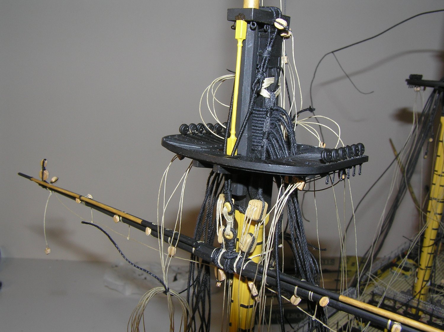
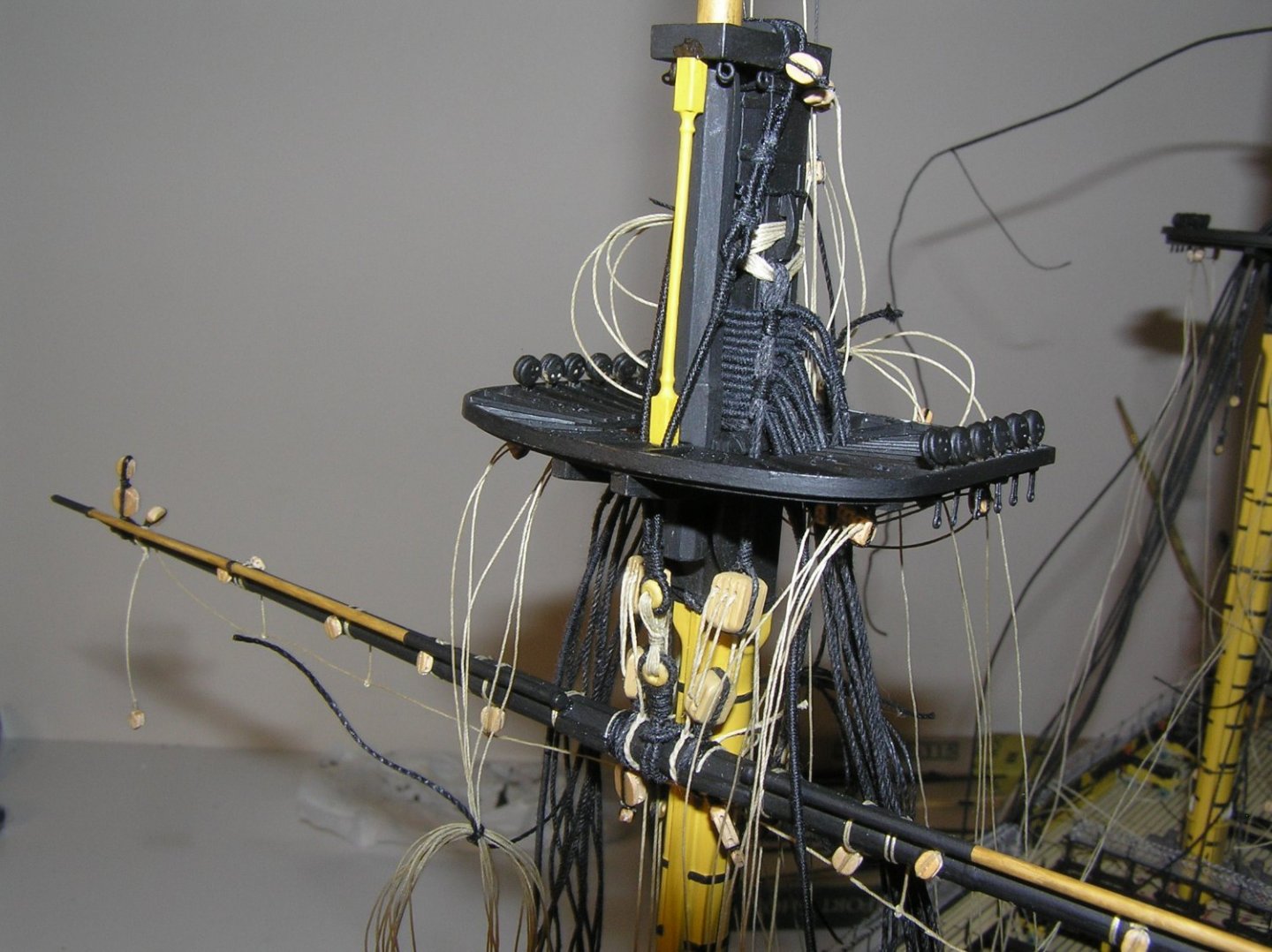
Bill, here is a shot I took of the fore yard once jeers and sling were done. Comparing to Plan 8, my upper blocks could have been higher up. 🤔
-
You're welcome. Longridge's detailed description was, for me anyway, too complicated at 1/100 scale. My model has no rose lashings anywhere. I just used single strops on the jeer blocks, albeit with large thread. I did timber hitch the falls to the yard, though, thanks to my trusty book of knots. 😄
-
The lower yard is suspended by two sets of jeers, each formed using two large 26" blocks. The lower blocks, attached to the yard, are double sheave. The upper blocks, suspended from the mast, are triple. The lower blocks are double stropped ie a spliced rope loop is doubled around them and seized, making sure to leave one long "leg" and one short "leg" protruding from the seizing (each of these legs is a little loop). The legs are wrapped around the yard, with the longer loop passing aft of the yard, just within the two cleats on the front of the yard (the sling collar is placed at the centre of the yard, between the jeer block straps). The two legs are lashed together with a rose lashing where they meet at the front of the yard. The upper triple block is also double stropped, making sure to leave a long leg which passes up through the lubber's hole and is suspended by seven turns of 4-1/2" lashing from an elm cleat attached to the opposite side of the masthead. The two sets of jeer lashings cross each other on the front and back of the mast. The actual jeer fall is a 7-1/2" rope timber hitched to the yard just inside of the straps of the lower block. It leads through the inner sheave of the triple block from fore to aft, then through the inner sheave of the double block, and so on until all five sheaves are full at which point it passes down to the deck and is made fast at the bitts. Hope that is clearer; Plan 8 is better than 10,000 words though! 😀
-
Thanks for your detailed answer. One reason I asked was because I remember the hassle of trying to plane & sand the concave interior of a cedar strip canoe I made years ago 😬
- 454 replies
-
- 1
-
-
- Union Steamship Company
- Stepcraft 840
- (and 3 more)
-
Out of interest, what is the final thickness for the lower hull? I guess you are leaving the inside "stepped"?
- 454 replies
-
- 2
-
-
- Union Steamship Company
- Stepcraft 840
- (and 3 more)
-
Something along the lines of this?? https://www.amazon.ca/SAILFLO-Pressure-Diaphragm-Caravan-Marine/dp/B0714BYP4N/ref=asc_df_B0714BYP4N/?tag=googleshopc0c-20&linkCode=df0&hvadid=292994045641&hvpos=&hvnetw=g&hvrand=951410644785312914&hvpone=&hvptwo=&hvqmt=&hvdev=c&hvdvcmdl=&hvlocint=&hvlocphy=9000682&hvtargid=pla-573486198452&th=1
-
Bill, she's looking great! keep up the good work! Happy modelling' Ian
-
I have no specific knowledge of these sheets, but the original aft position for the bollard makes sense to me because it leaves enough length of rope for several men to keep it taut as a crewman behind them belays the slack end on said bollard. Or, as you say, they could stop it at the fairlead then belay to the forward bollard. See the following video; the woman stands on the rope at the fairlead at about 1:55. Also, the Portuguese re-rigged her as a barquentine in which case she would not have had a cro'jack. So maybe they moved the bollard forward for some other purpose. For what it's worth, my ancient Revell CS has the bollards aft. By the way, your model is magnificent! Especially as a first build.....
- 525 replies
-
- 1
-
-
- cutty sark
- mantua
- (and 2 more)
-
Gregory, are you in the USA? Maybe it's ok in that direction. Thanks for mentioning Crafty Sailor in Calgary - I never heard of them before, LOL. Their rope certainly comes in many sizes! Will keep them in mind from now on.
-
Beautiful travellers! And ship, of course....😉
-
One thing I have run into several times is excessive shipping fees from USA to me in Canada. I don't know why USPS is so expensive into Canada. For example, when I wanted to buy a Heller "Preussen" kit, it was significantly cheaper to pay postage from France than from Connecticut. I could drive to Connecticut in a day 🤔. Books too. I have ordered several ship books from the UK instead of the USA for the same reason. And small parts. It's often cheaper for me to order from Model Dockyard or CMB in the UK, than from say MS in the USA. Just sayin'
-
Kevin, looks much like the thread and bobbins that came with my Cutty Sark and Constitution kits, in the 70's. Could it have acquired the green tinge over time for some reason?