.JPG.3b858ae7db6d3e5e48507bb4328943a5.JPG)
jlefever
-
Posts
156 -
Joined
-
Last visited
Content Type
Profiles
Forums
Gallery
Events
Everything posted by jlefever
-
HO trains and layouts by popeye the sailor
jlefever replied to popeye the sailor's topic in Non-ship/categorised builds
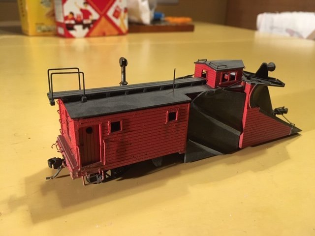
Wow, that's a memory, the snow plow that is. Built that kit about twenty years ago. Still have it, a bit dusty and missing the brake wheel but I feel like it came out OK. Those old wood kits could be a lot of fun in the days before laser cutting simplified things. Jim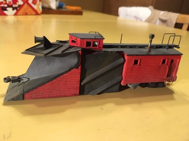
- 72 replies
-
- 12
-

-
Looking really sharp. Nice paint work and the blocks and baggywrinkle work very well. You're on your way to a real beauty. Jim
- 140 replies
-
- 1
-
-
- benjamin w latham
- model shipways
- (and 1 more)
-
A clean sharp looking project. I like it. Jim
- 70 replies
-
- 2
-
-
- Lowell Grand Banks Dory
- Finished
- (and 1 more)
-
A really sweet project, Sorry I hadn't found it earlier. Jim
-
Nice looking project! Definitely worth checking out. Jim
-
Dove by jlefever - 1:48 - Pinky Schooner
jlefever replied to jlefever's topic in - Build logs for subjects built 1851 - 1900
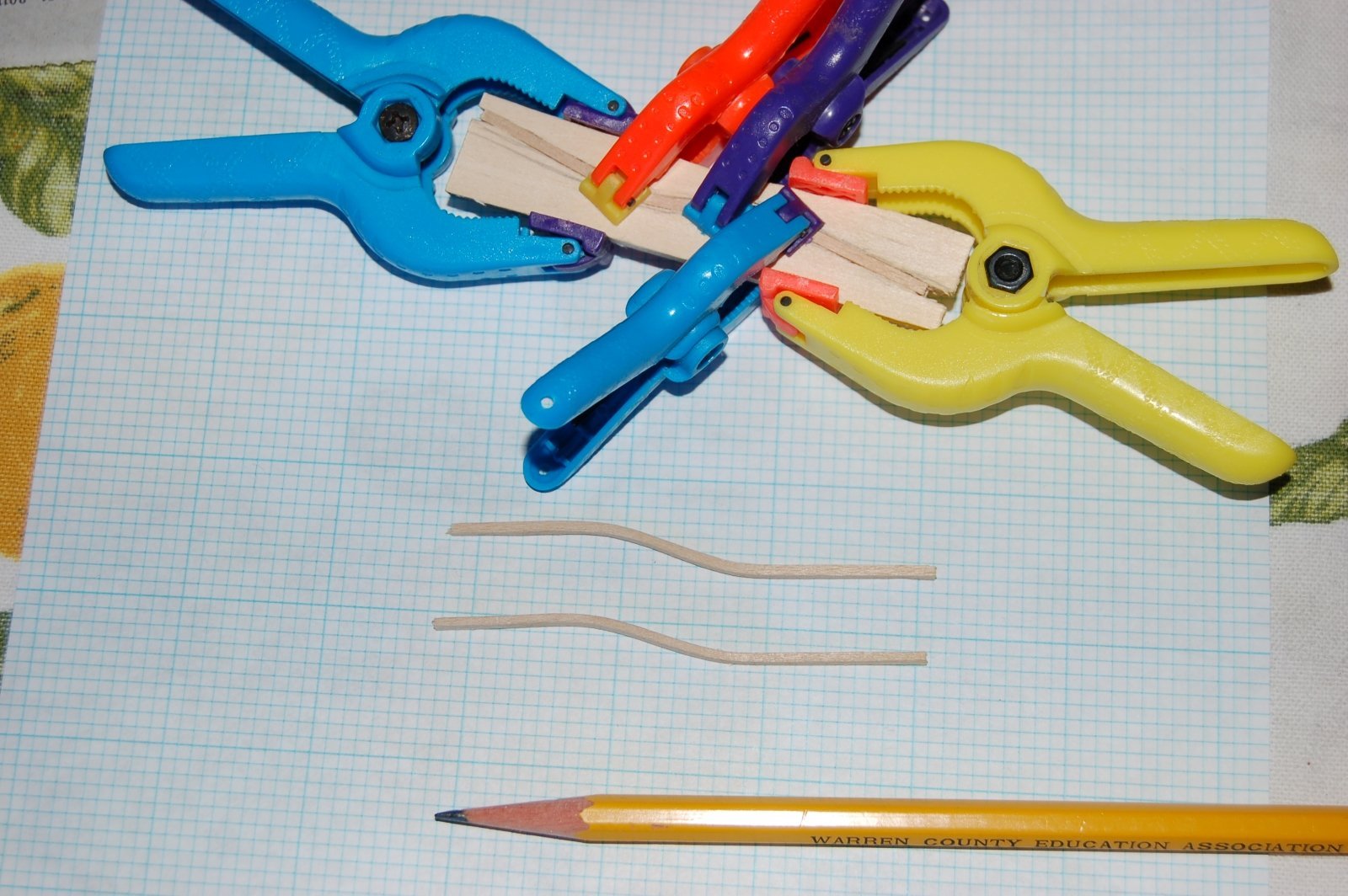
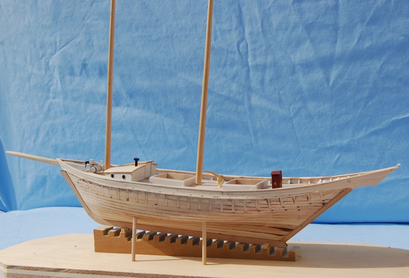
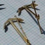
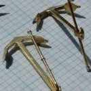
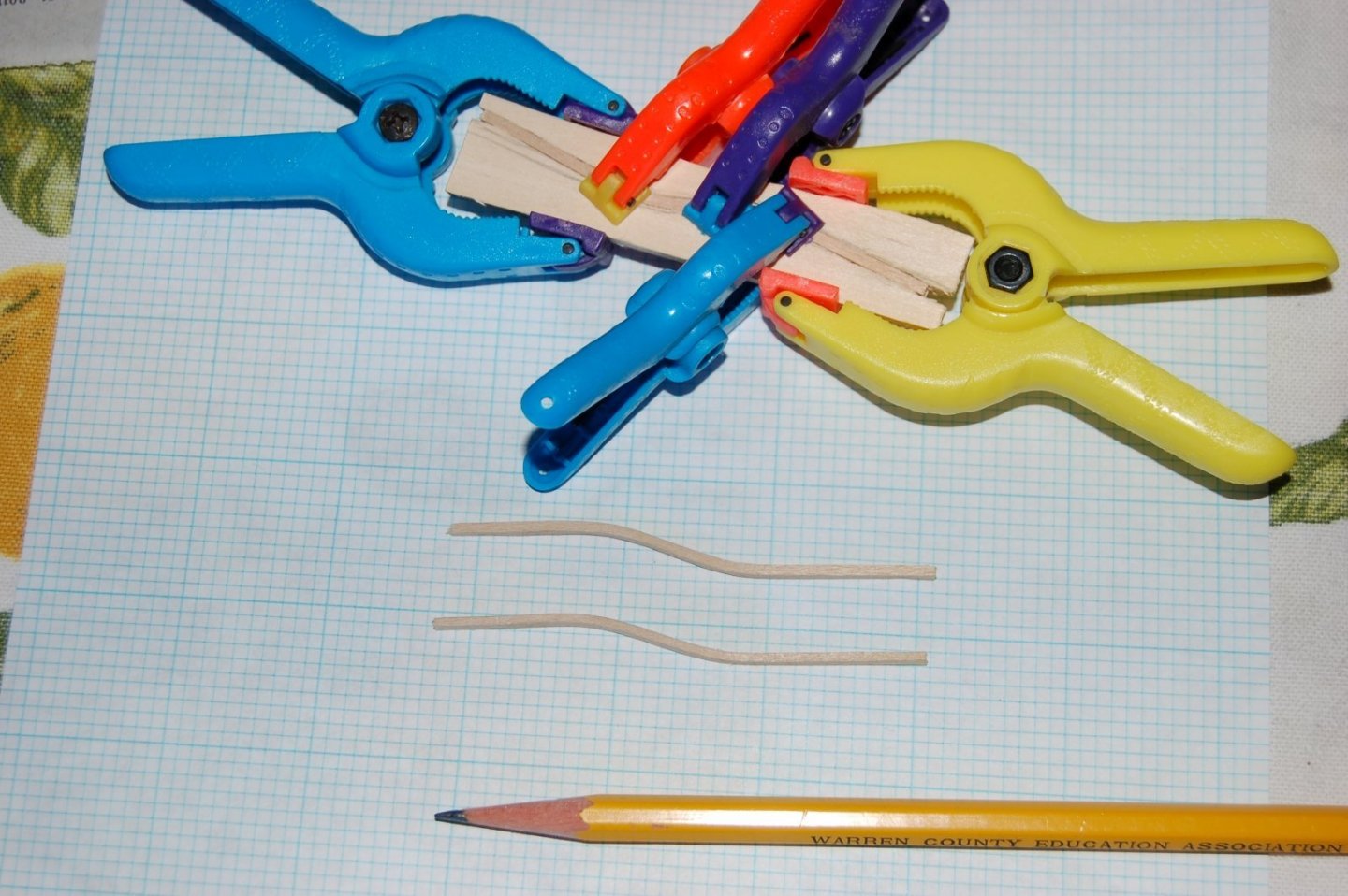
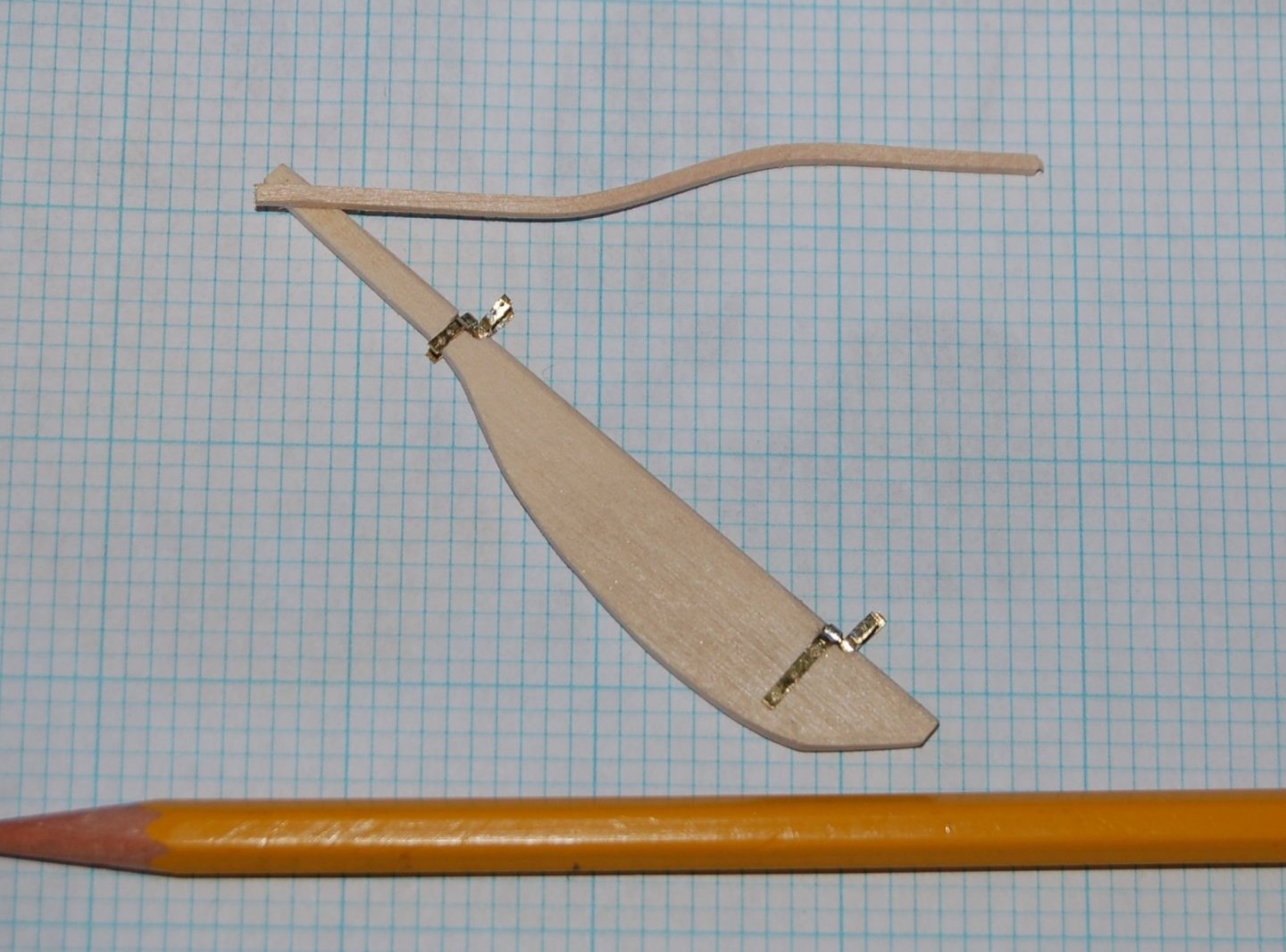
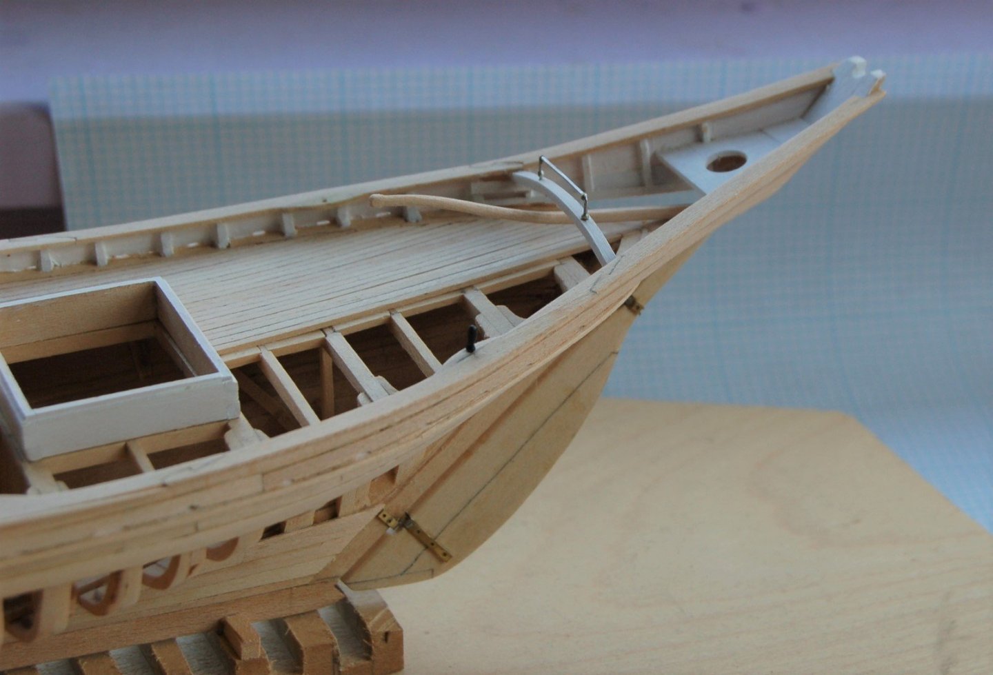
A Rudder for the Doves The first challenge in hanging a rudder, making a set of tiny gudgeons and pintles. Even at quarter inch scale, they wouldn’t be big but could I make them work? In previous models I had simulated these bits of hardware with nonfunctional paper or brass straps. For the Dove the goal was a closer representation of the real thing. Here’s where I ended up. Figure 15‑1 - Gudgeons and pintles These tiny hardware bits are smaller than they appear in this image. The graph paper on which they sit is divided into 1/10th inch squares and the straps fit snuggly on 1/8” thick stern post material. I made them by soldering fine brass tubing onto brass strips which were then drilled and bent into shape. The pintles were of similar construction with a bit of brass wire added to make the pin. The strips are 1/16” wide and .017” thick. The pintles swing freely in their gudgeons. The Tiller In order to achieve the tiller’s characteristic curve wood blanks were steamed and pressed into shape as they cooled and dried. Figure 15‑2 - Forming the Tiller From time to time, I’m actually smart enough to guard against adversity by making an extra and sure enough this time one of the blanks cracked as it was receiving the final shaping. The rudder parts laid out When I laser to cut the keel, stem and stern posts I also cut a rudder blank for each Dove. Here the gudgeons and pintles are dry fitted to the rudder blank and the newly formed tiller is set approximately in place. The tiller still needs a bit of carving and to be cut and glued into the rudder stock. The various hardware bits also remain to be trimmed and glued in place. They look quite a bit smaller in this image than they did in the initial image for this section. Figure 15‑3 - Dry Fitting the Rudder Parts Like the stern post, the rudder has an impressive rake. Thinking about the angle of the rudder it was hard for me to visualize the way the tiller would swing. Here the rudder is dressed up, fitted to the stern post is glued in place on the framed Dove. Figure 15‑4 – The Rudder in place. Figure 15-5 - Rudder in place seen from above. In addition to mounting the rudder, a curved beam has been attached to the stern rails to support the main boom horse. The rudder is movable and the curve and location of the beam and horse allows the tiller to swing from rail to rail. There is also a smaller horse for the fore mast in front of the main. They are made of nickel wire. The rudders were a fun project. Jim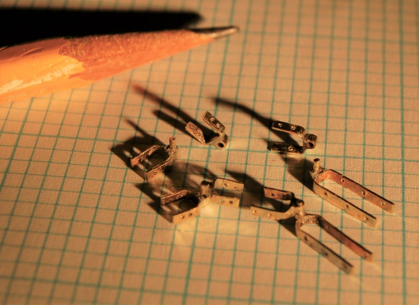
-
Dove by jlefever - 1:48 - Pinky Schooner
jlefever replied to jlefever's topic in - Build logs for subjects built 1851 - 1900
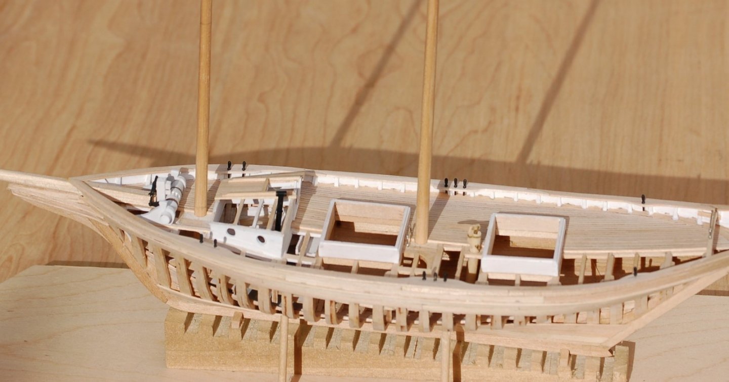
With the major task of planking behind me the next few posts will jump around a bit as I figure out how to add additional detail to my projects prior to rigging. Today it's belaying pins. I think perhaps due to her size the Dove's pins are smaller than typical but as is often the case I started with Chapelle and his book on fishing boats. There I found a detail of a typical belaying pin on which I based my work. So far I haven't bought any premade parts. My pins would not be the first. I had two problems, first with the rails only a foot above the deck - pins of the length shown in Chapelle would have fouled the deck. A standard handle with shorter shaft would have to do. Second, without the tools to turn metal or tiny wood parts I needed an approach within my skill set. I settled for composite pins. I started with 1/16" square basswood sticks into which I drilled and epoxied brass rod. Then, chucked the brass into my Dremel and turned it against a profile filed into the edge of a razor blade. The wood is shaved away until the neck just touches the metal. The finished shaft and neck of the handle are pretty close to a scale 1" dia. A little work on the wire end with a file and a bit of paint and I had what I hoped was a presentable shape. Below are the pins set into the Dove's rail. Fortunately this small vessel didn't call for too many pins. The pins end about three inches short of the deck. Next up will be a way to steer the Dove. Thanks for looking, Jim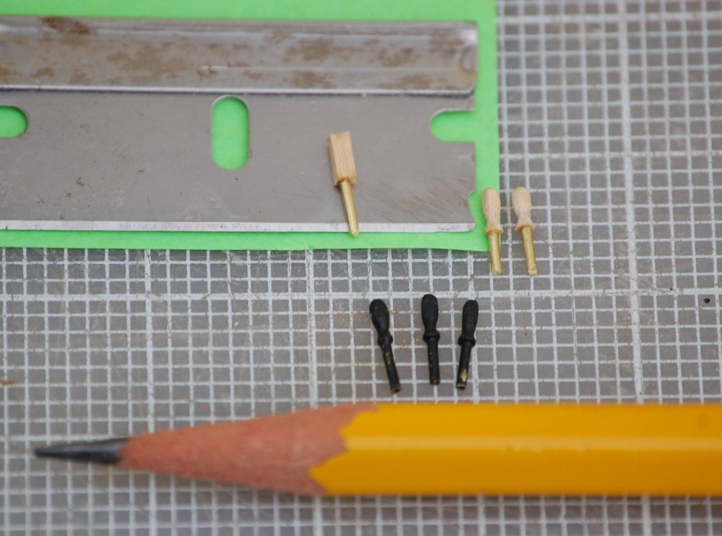
-
Dove by jlefever - 1:48 - Pinky Schooner
jlefever replied to jlefever's topic in - Build logs for subjects built 1851 - 1900
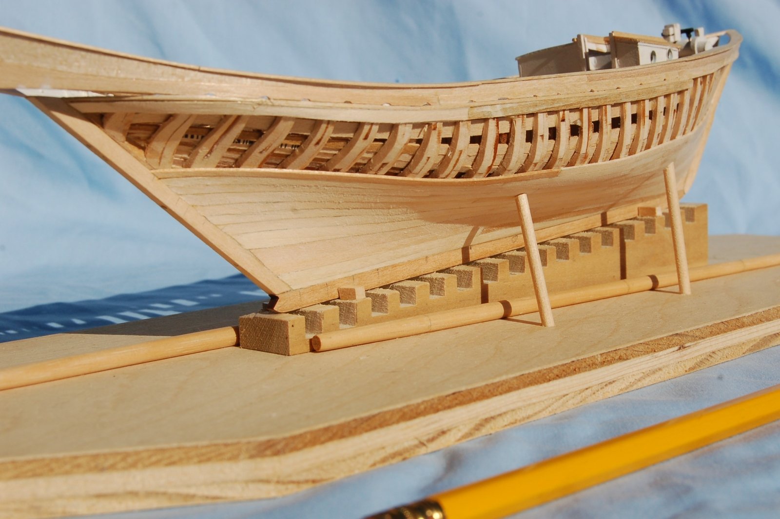
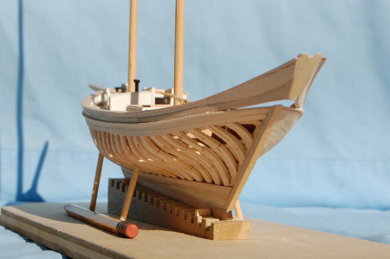
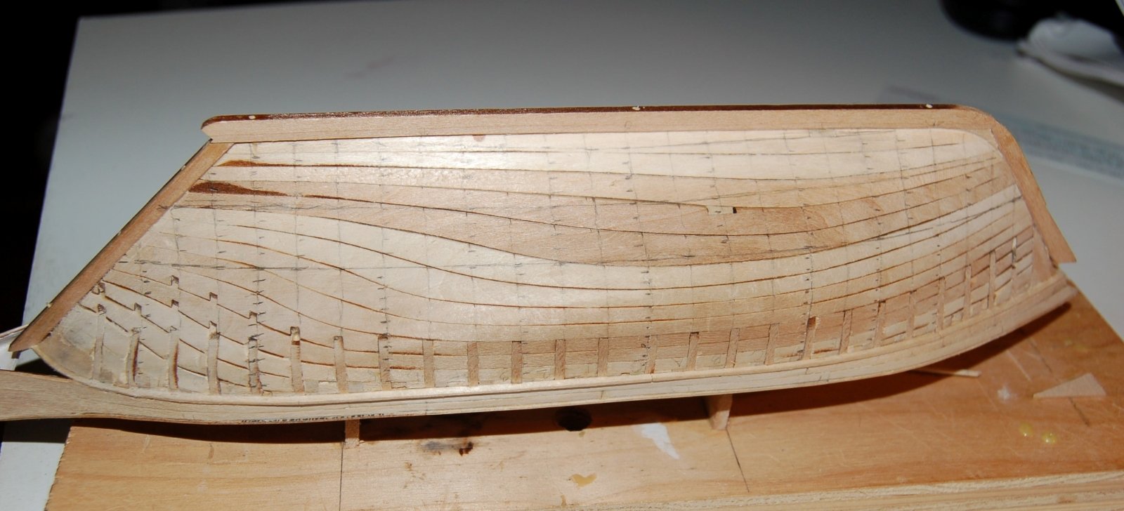
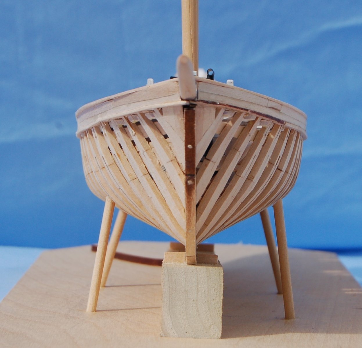
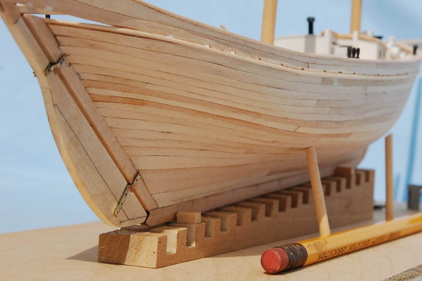
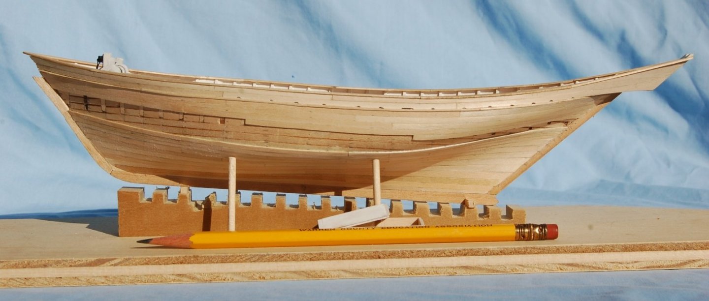
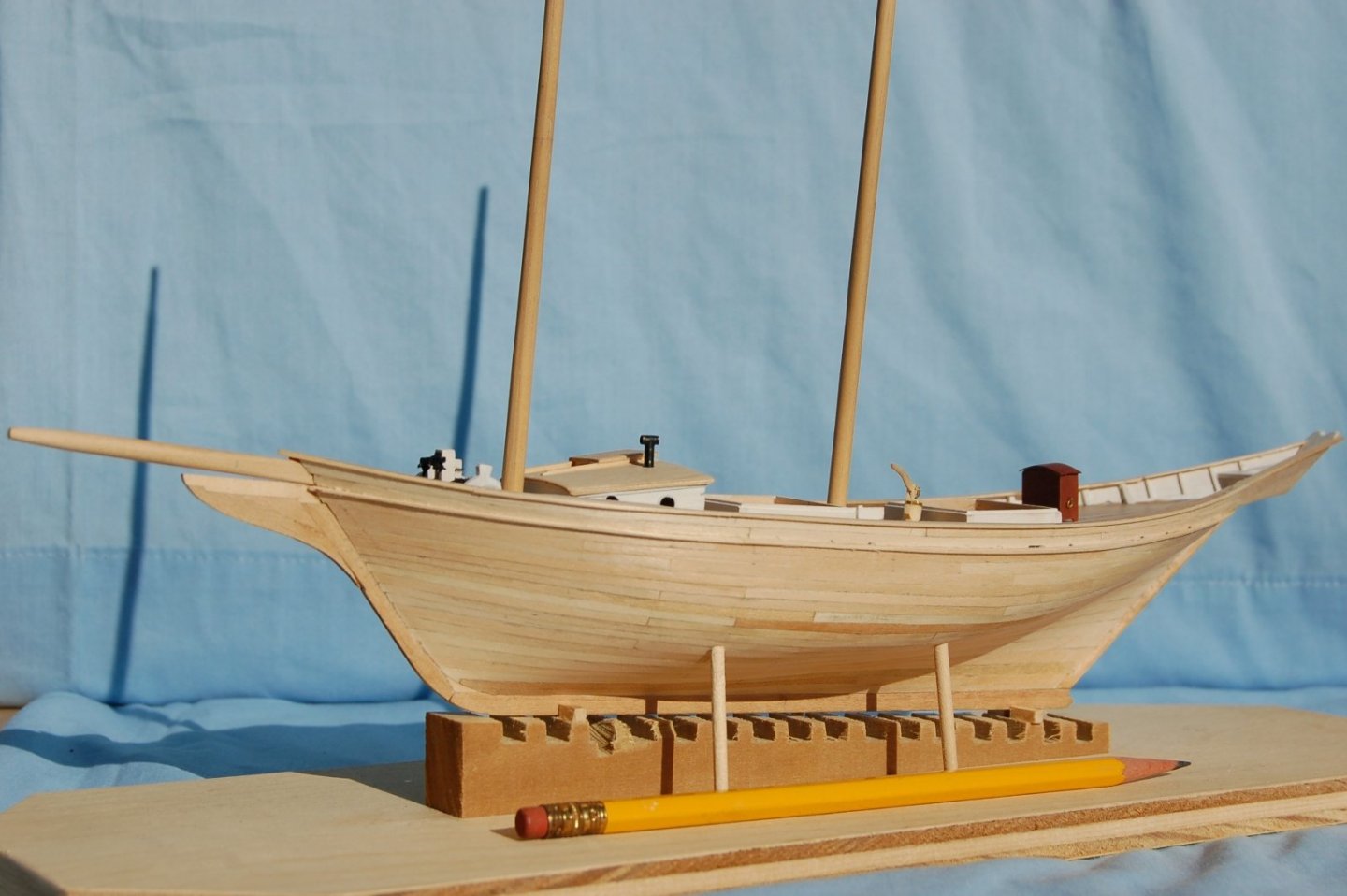
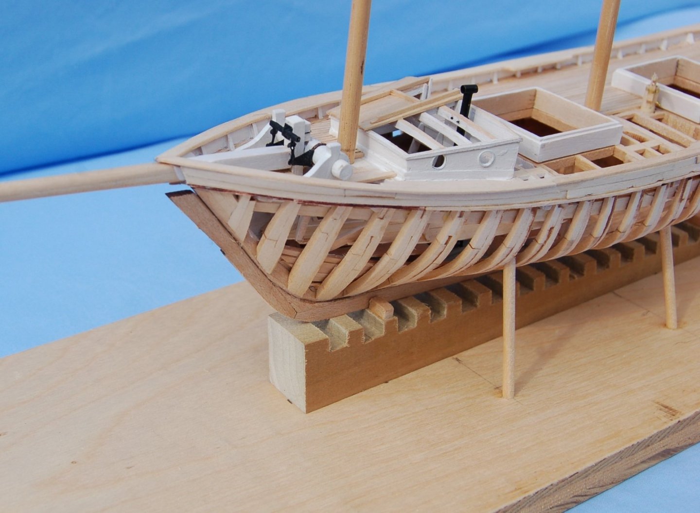
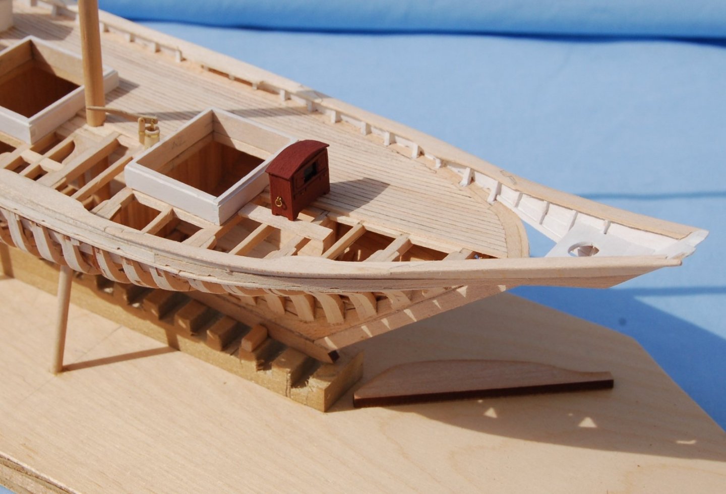
Solid Hull bow Progress. At this point the planking was beginning to approach the meet up line as I worked both upward and downward. Figure 14‑8 - Solid Hull Bow Planking Nears Completion You may notice that the planking of the floor up to the turn of the bilge is wider than the planks applied above. This is based on the planking sizes indicated in Chapelle’s scantling section. Similar progress on the starboard side of the framed hull. I’m enjoying the sweep of the planking as it’s developed along the side of these little ships. I’ve probably made a fair number of mistakes but I like this image. One thing I’m feeling pretty good about is the fairing of the framing. So far, the planking has gone on reasonably smoothly and I haven’t found spots where the frames needed to be shimmed or trimmed as I progressed. Figure 14‑9 - Starboard Side Planking - Framed Dove Standing tall in the stocks, the solid hull Dove nears completion. Figure 14‑10 - Only a Few Planks to Go Finished up. Figure 14‑11 Solid Hull - Planked In the previous view, the solid hull model is planked and looks to my eye, quite ship shaped. At this point the cutwater has been fixed to the stem further enhancing the ready for the water effect. The following image shows the Framed Dove. You can’t quite see it but she’s completely planked on the starboard side. What you see on the port side is pretty much what she will get there. Figure 14‑12 - Framed Dove - With All the Planking She'll Get There are lots of fiddly things to do yet but I have to say planking these two models was very rewarding. It felt good going on and I think looks pretty good finished. I tell myself that this is due to the planning in the early stages of the project but luck and the use of thin (near scale thickness) materials were also important factors. The next sections will cover additional details added to the Doves prior to starting rigging.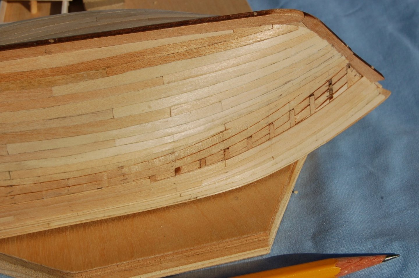


-
Looks like it will finish up nicely with lots of warm woodwork. Jim
- 153 replies
-
- 1
-
-
- Ancre
- Bruno Orsel
- (and 2 more)
-
I'm really enjoying following this build. For those interested in this topic (these ships) I'd like to recommend: End of an Era The Last of the Great lakes Steamboats by David Plowden it's available from Amazon and at prices substantially lower than the cover price and is filled with great black and white images of these vessels and the men who operated them. Lots of great detail images. Jim
-
Dove by jlefever - 1:48 - Pinky Schooner
jlefever replied to jlefever's topic in - Build logs for subjects built 1851 - 1900
Thanks for looking and for the encouragement, There's an advantage to using a thin flexible material. The hull form also doesn't require torturous bends. I also find it interesting the way the planks seem be smooth while crossing the joints in the horizontal lifts at a pretty steep angle. The lifts are horizontal, the planks are sweeping upward a couple of scale feet. Jim -
Dove by jlefever - 1:48 - Pinky Schooner
jlefever replied to jlefever's topic in - Build logs for subjects built 1851 - 1900
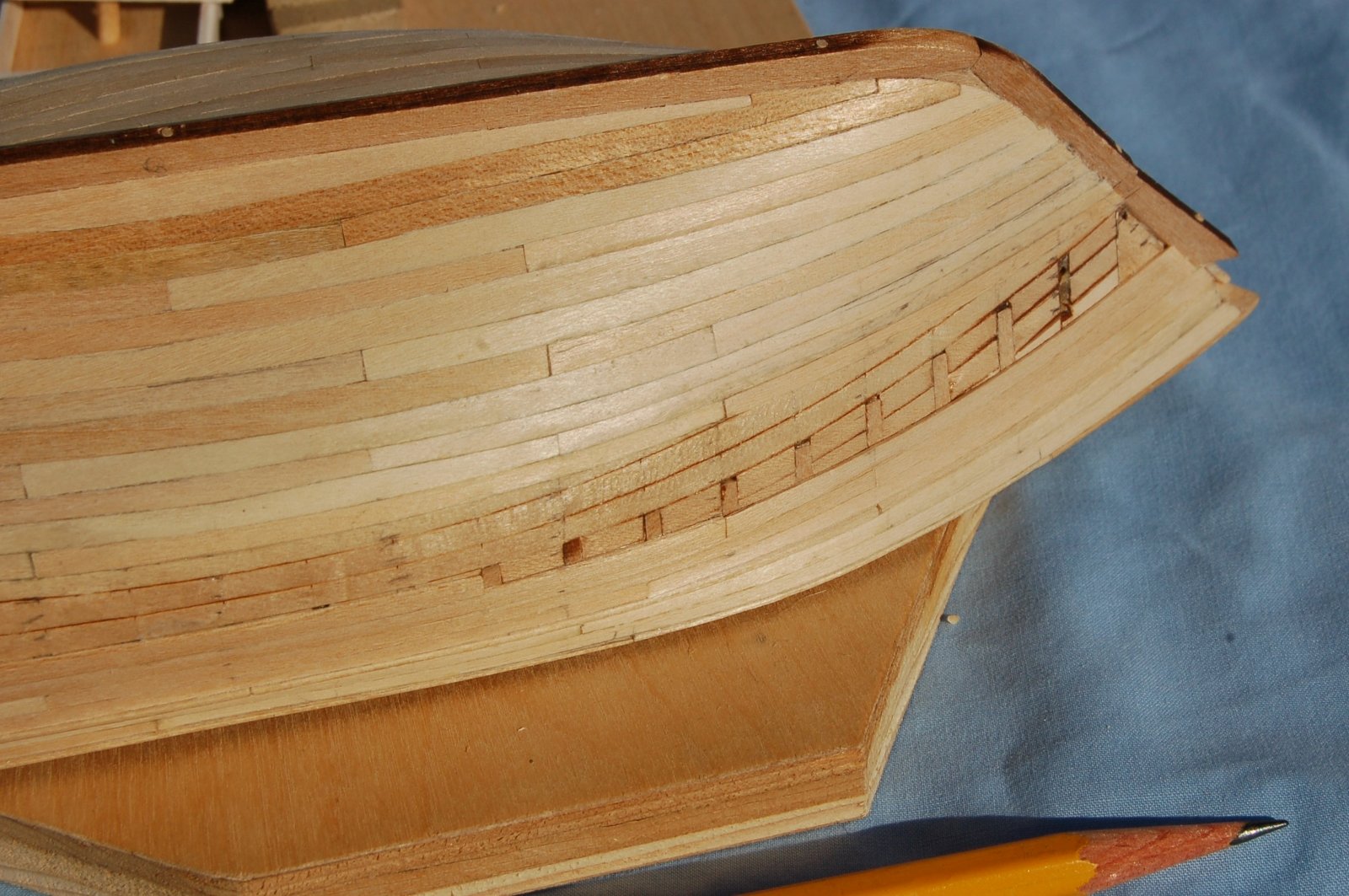
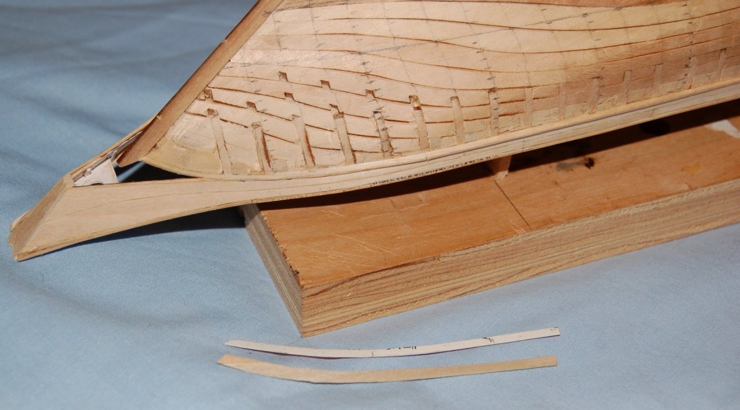
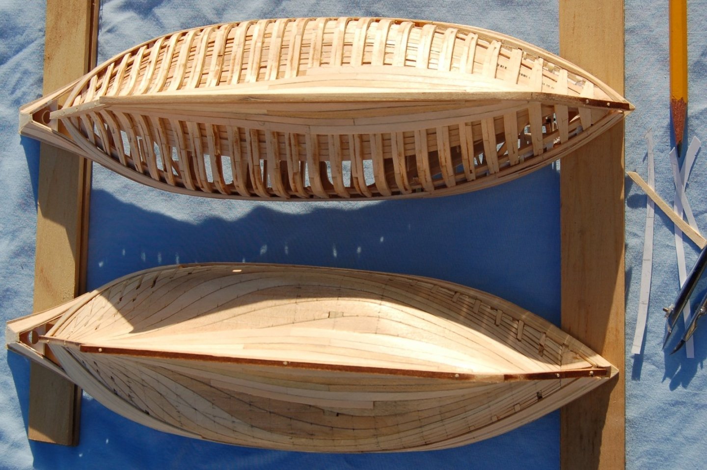
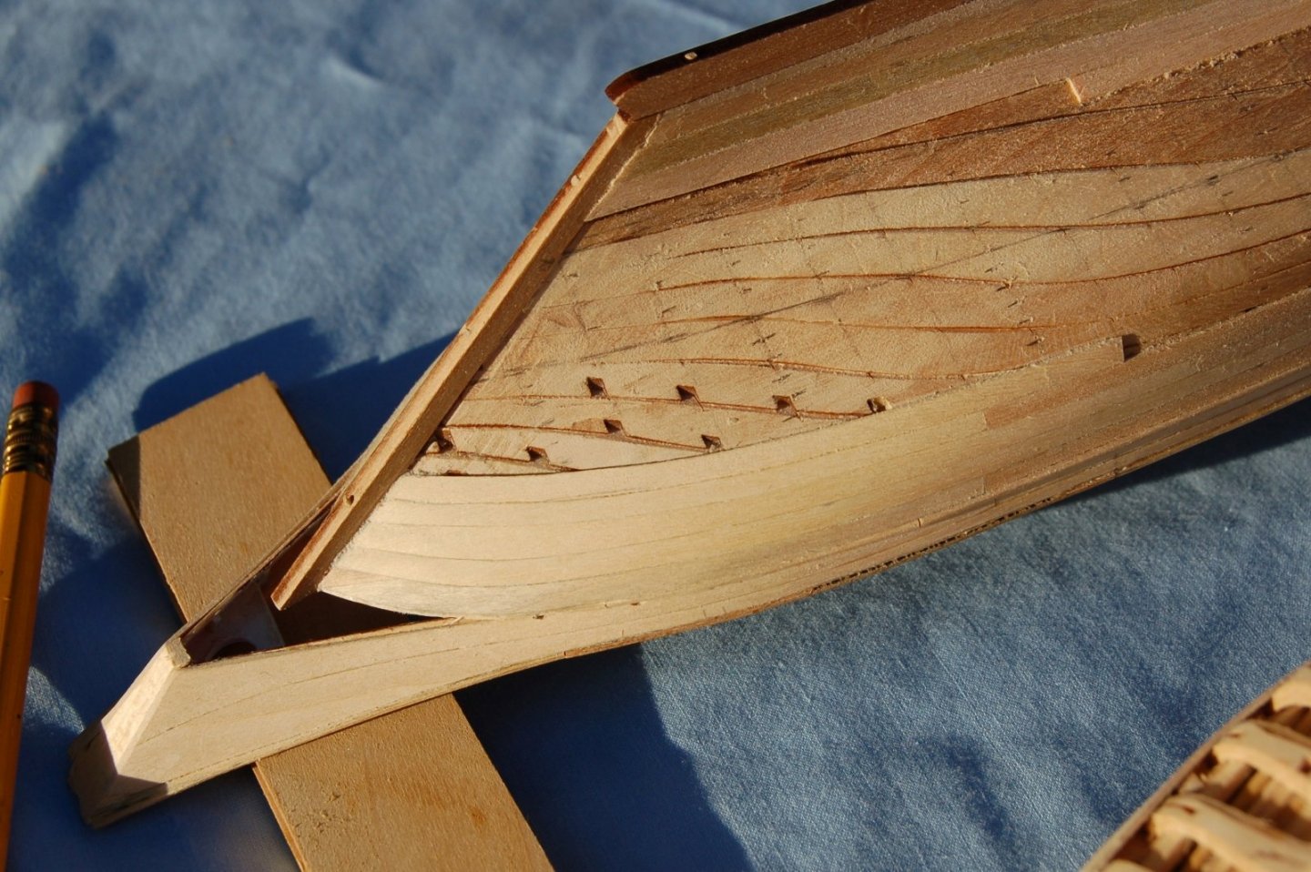
Planking With the stem and stern posts in place and the ribs having received their final tune up The Doves were now ready to Plank. Figure 14‑1 - On the Stocks Ready for Planking The drawings show the Dove’s planking as having a finished thickness of 1 5/8”. These doves would be single planked with 1/32” stock which scales to 1 ½” thickness. I believed this would be close enough to prototype dimensions. Starting with the solid hull Dove I began to plan the planking work. Planning the planking effort My plan was to use the solid hull model to work out my planking as it made a stable base and would take some abuse. The first step was to establish the stations on the hull. This was done using the burned in hash marks created during the laser cutting process. Using a pencil, I connected the dots from keel to rail for each station. The hull was then divided into bands with the first representing the garboard and two additional lines representing the floors and the turn of the bilge. Finally using a compass (bow pencil from my old drafting days) I divided each band into equal subdivisions. The work was fussy but without problems and the relatively easy run of each plank or strake seemed to indicate that stealers would not be needed, essentially that the relatively easy taper of the planks would be sufficient to accommodate the changes in the hull profile. Figure 14‑2 - Planking Layout The plan was then to transfer each plank to paper strips matching the hull’s curvature and with the width of the proposed plank transferred to the paper strip a station at a time with my compass. Once I had a paper strip that fit, I would cut wood. The first plank Here is the first plank, the uppermost plank at the stern rail. It has been laid out on paper, transferred to my 1/32” thick stock and cut to shape. You may note that in this case I’m using pretty extreme spiling to avoid needing to bent the plank too much across its width. This way I avoid steaming, soaking or heating my planks as I go. This method works for me as my 1/32” material is relatively cheap and I can afford to waste a fair amount cutting the planks. Figure 14‑3 - First Plank Shaped and Ready to Apply As a side note, between the stern post and the last stanchion there is a fair size dab of wood filler. To the best of my memory this is the one time I’ve used filler on the Dove project. It’s been used here because I want to be sure I don’t have a void below my planks, although, as I think about it, that area is certainly a void on my framed model. This first plank is curved quite a bit but it is in any case the most extreme example. The planks straightened out as I went. Planking Underway In the following images you see the planking has been started on both Doves. In both cases I’ve installed the garboard along the keel and started to work the planking upward toward the turn of the bilge and ultimately the planksheer. At the same time planking has been started just under the planksheer which will be worked downward to meet the planking coming up the hull. Because of the thin material and the curvature to which I’m cutting many of the planks I find I’m able to simply flex the planks into place gluing them down with small dabs of carpenter’s glue and holding them in place with my fingers until the glue begins to set. To the right of the image, you can see a small pile of my paper templates. Also, you might note that the planking layout I’ve marked on the solid hull Dove appears in complete form only on the port side of the model. At this point I’m proceeding as if both sides of both models are identical. I use the template made on the port side of the solid hull to produce four planks which are then applied to both sides of both models. In retrospect this seems a bit foolish but luck was with me as the method seems to have worked. Figure 14‑4 - Planking Underway Planking Progress Here is another view of the same progress. There a few lumps and bumps but in general the planking is running pretty much as planned. Figure 14‑5 - Planking at the Bows Another Closer view of the framed Dove showing the planks laying down at the stem post. Figure 14‑6 - Framed Hull - Bow Planks You may notice a bit of wood dust in this and other images. This is a variation of the old millworker’s trick. I lightly sand the planks after the glue has begun to set effectively pressing wood dust into the freshly glued joints and closing any gaps that remain between the planks. Progress planking at the stern of the solid hull model. The planks at the stern of my Doves, just below the planksheer proved to be the trickiest to shape and install, exhibiting the most curvature. As you can see in this view after only five planks, things are beginning to straighten out allowing me to cut less curved strips. Also at the bow, I've used nibs on the first three planks. I’m not using a strict joint pattern but rather I’m trying to keep the plank lengths between 20 scale feet and around 8 scale feet and holding the joints to a minimum of two stations apart on adjoining planks. It’s also interesting to note the angle of the planks as they cross the bread-and-butter sections of the hull. The relatively easy run of the planks in the aft portion of the hull certainly does not match the hull’s horizontal water lines as they sweep upward toward the after end of the hull. Figure 14‑7 - Stern Planking - Solid Hull Model That's it for today, next time I plan to finish up the planking.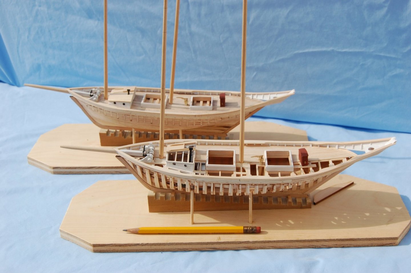


-
Dove by jlefever - 1:48 - Pinky Schooner
jlefever replied to jlefever's topic in - Build logs for subjects built 1851 - 1900
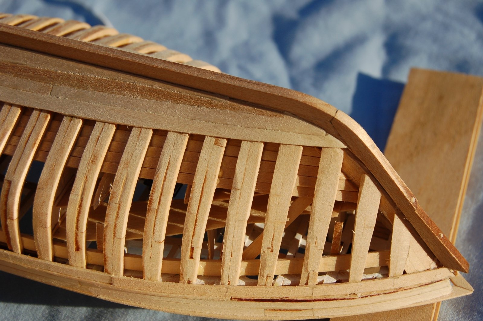
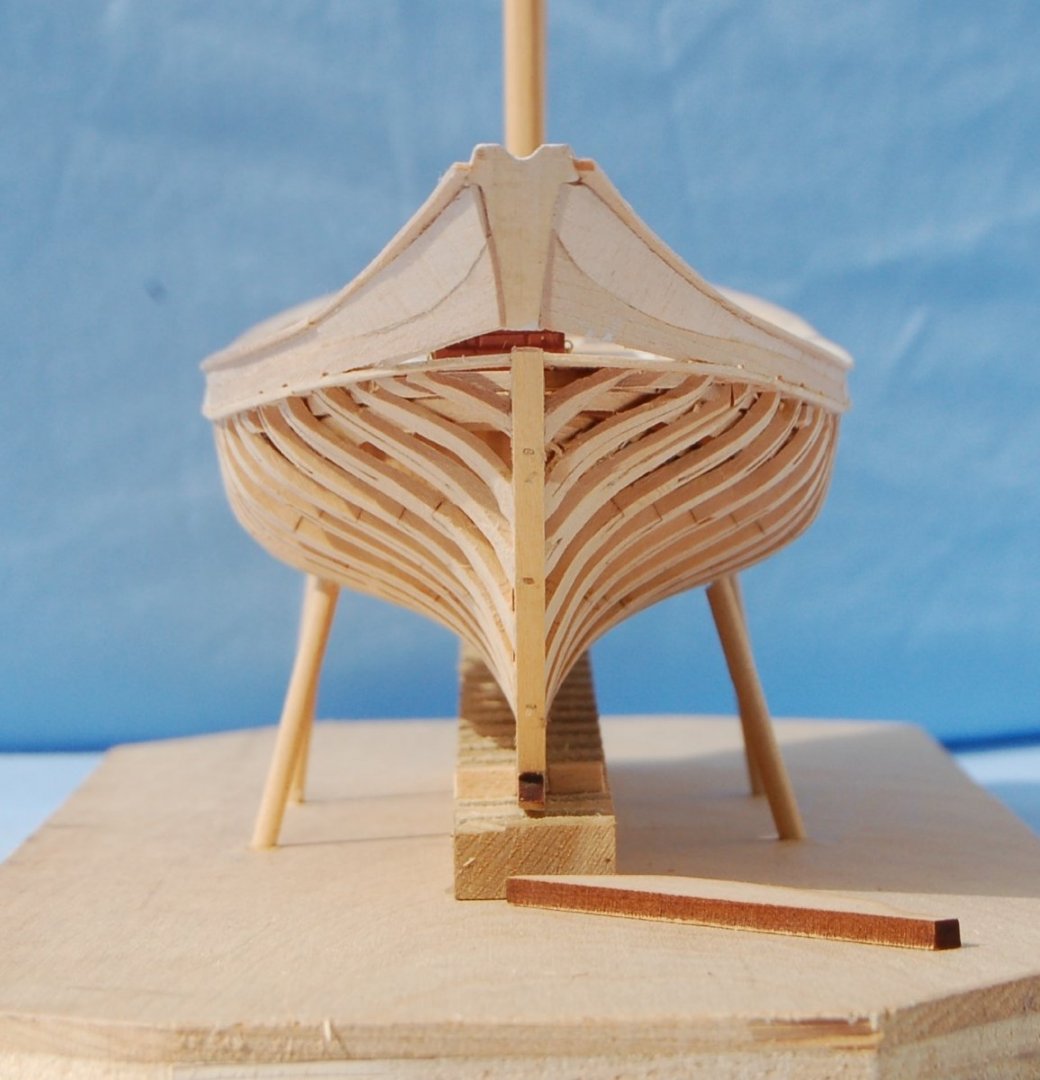
Getting Ready to Plank Removing the Dove from its framing jig, I had snipped as close to the quick as I dared, now it was time for finer tools. I moved on my hobby knife then to sand paper. In the following view, the shaving has just begun but already the shape of the Dove’s lines is improving as the now useless tabs are sanded away. Figure 12‑5 - Clean-up Progressing Also apparent in this image is the ragged ends of the ribs at the aft deadwood and stern post. This will need to be cleaned up before planking starts. Only a couple steps remained before I could begin to plank my Doves. They included mounting the exterior portions of the stem and stern posts and making any needed final tune up of the ribs or in the case of the solid hull model the lines. The posts had been laser cut when I cut the keel. Now I glued and doweled them into place then cut the bevel into the keel and posts and made final adjustments to the ends of the ribs as I went. In general, the ribs proved to be in good shape and needed very little additional smoothing (fairing) as I did my final cleanup. As you may recall, the primary fairing had been done when the ribs were initially glued up. Here’s the bow of the framed Dove: Figure 13‑1 - Ready for Planking - Fore As we noticed at the end of the last section, aft the Dove’s ribs looked a bit ragged where they feathered out at the deadwood and keel. With the stern post in place, I was able to work the bevel along the keel and post, beard the dead wood above the keel and at the same time smooth up the ragged ends. Here's how she came out: Figure 13‑2 - Beveled and Bearded – Aft Compare this image above with the last image in the previous post. Ready for Planking, here’s how she looked at this point front and rear: Figure 13‑3 - Bow Framing Figure 13‑4 - Aft Framing At the same time, I prepped the solid hull for its trip to the planking shop. This proved to be little more than attaching the stem, keel and sternpost and working the bevel and bearding along the join. Here’s how it was looking at this point: Figure 13‑5 - Solid Hull Cleaned and Ready for Planking Beginning to look like a tidy little ship. In this image you may get an idea why in ships of this type they put the cabin in the bow. Small as the cabin was, there was certainly very little room for any kind of accommodation astern. Next post, planking starts. Jim


-
One thought does occur as I read through this post, that of the unknown builder. I've never been a fan of putting my name front and center on my projects but It feels as if it should be there somewhere. I'm thinking on my various modeling efforts as well as other art and craft efforts that the minimum may be a label on the bottom or back of the case including my name, date of construction and source of the model or plans. Something to give a future owner a bit of a story to tell. I hope you are able to learn something of this apparently quite skilled modeler. Jim
-
Repair looks good so far. I think one of the great satisfactions in modeling is earned over time... the ability to roll on past disasters. We all have them.
- 85 replies
-
- 3
-
-
- Lowell Grand Banks Dory
- First Build
- (and 2 more)
-
Nice model indeed! You might like to check out the on-line publications at Gutenberg Project, they have a free download of Chapelle's monograph "Migrations of an American Boat Type" (published by the Smithsonian and now out of print) which include plans and photos for a North Carolina sharpie schooner with is similar but has a less developed bow. Looks like a fun project. Jim
-
Dove by jlefever - 1:48 - Pinky Schooner
jlefever replied to jlefever's topic in - Build logs for subjects built 1851 - 1900
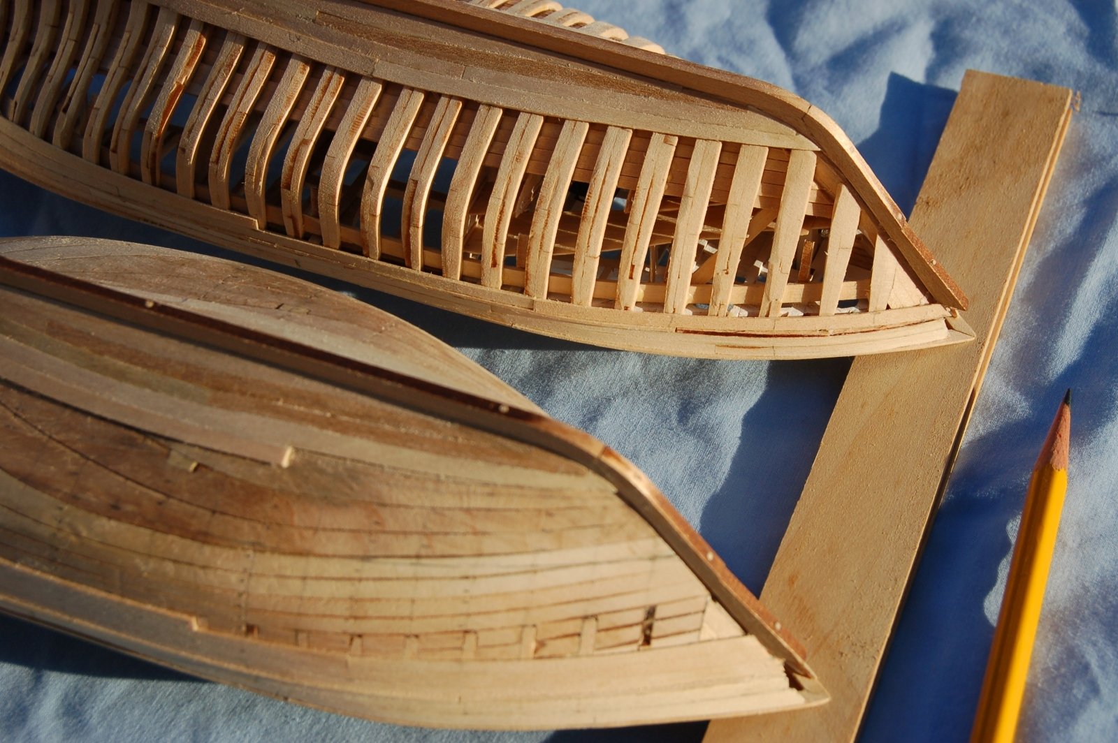
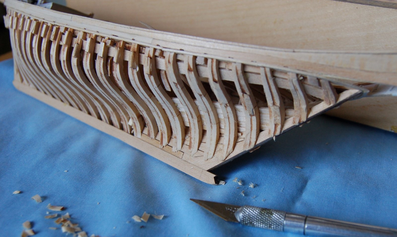
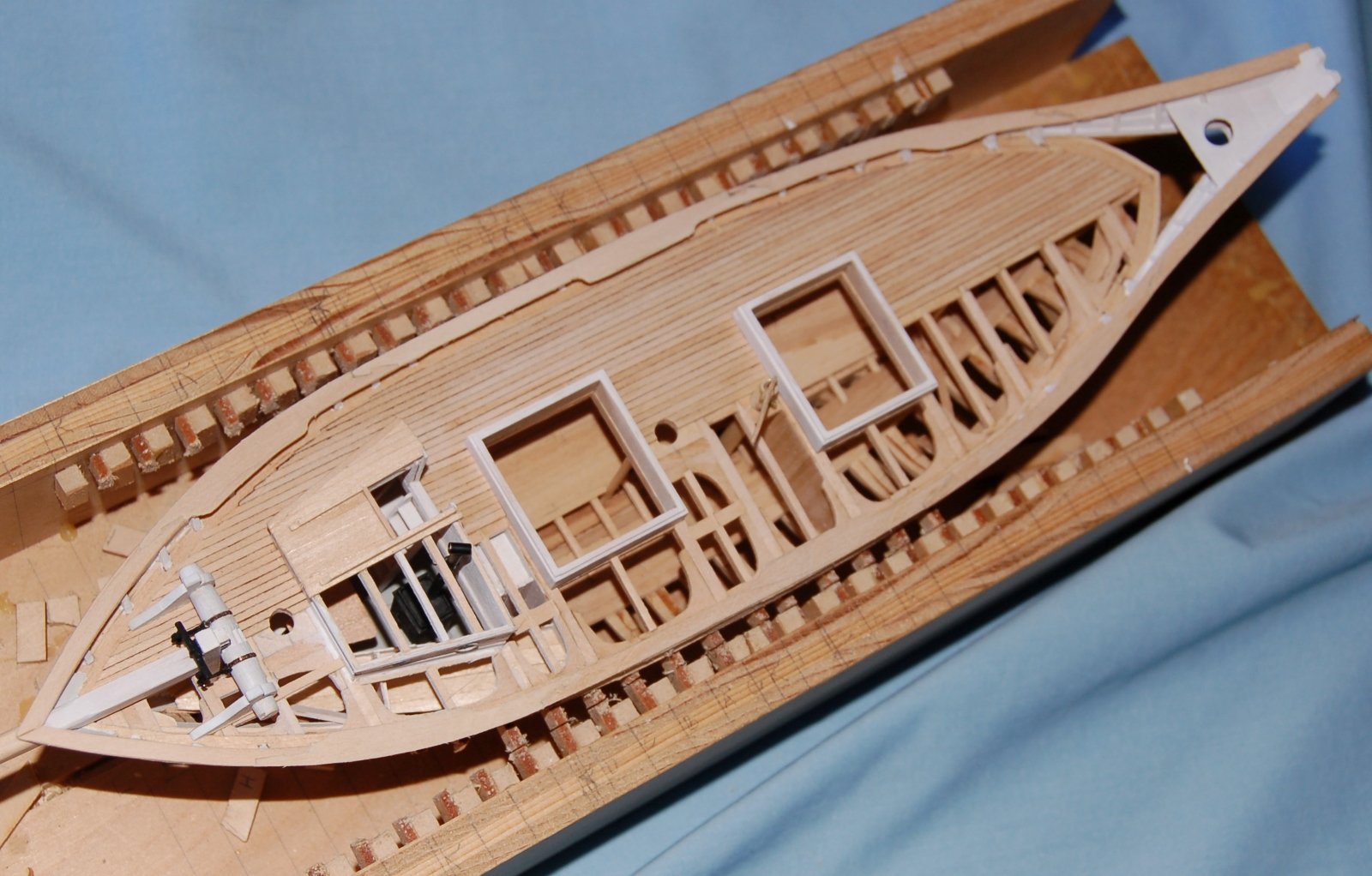
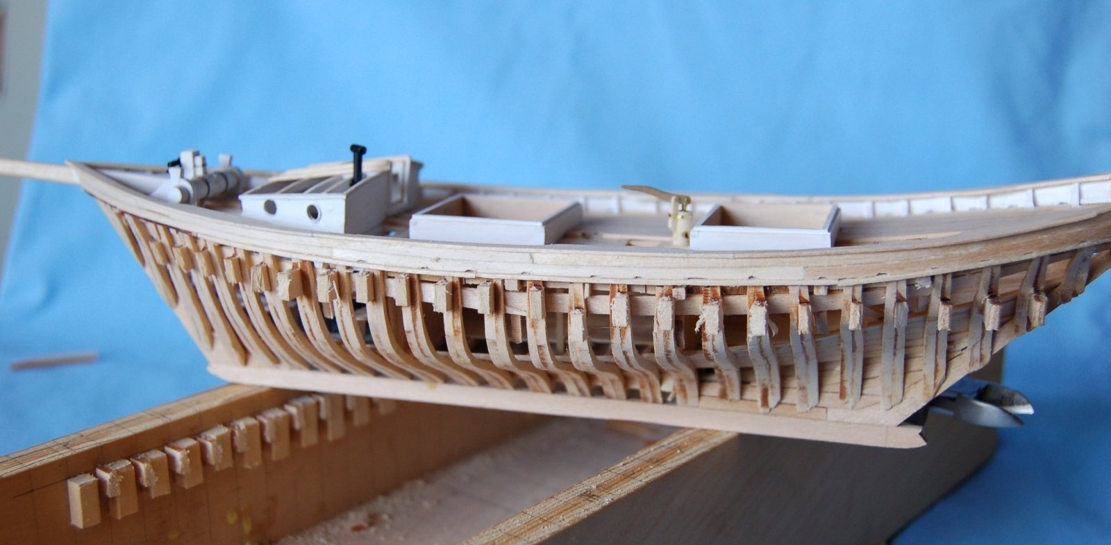
Cutting Loose OK, here goes… I’ve avoided cutting my framed model out of its box jig as long as I can. First if you’ll permit me, a couple thoughts on using this type of jig. Using tabs cut along with the ribs was, to the best of my knowledge, my innovation but the notion of using a jig to set up and support the keel and ribs during the early phases of model construction was hardly a new idea. The jig had a variety of purposes, basically an aid to setting up the frames and supporting them as I started the project. It served the basic purpose of keeping the frames in line and preventing them from being pressed open or pinched together. To a lesser extent it established the set up spacing and prevented the frames from shifting fore or aft as I worked. Finally, it facilitated construction of the Dove’s interior, the deck framing and planking. For a model of this size at least, it was sturdy and rigid, had provided easy and predictable access to the ships interior and it protected the frame members (with the exception of the stanchions) admirably well. But I could no longer avoid working on the Dove’s bottom and there was no getting at that inside the jig. It was time to cut my Dove free. Figure 12‑1 - The First Cuts Made - So Good, So Far If you remember, when I set up and lasered out the tiny rib pieces I had arranged them so that the wood grain went parallel to the long axis of the piece. As a result, the join between the rib and its supporting tab was set up so the grain crossed the tab parallel to the face of the rib. Further I had partially burned through the join when the pieces were laser cut. All this was primarily to keep unplanned fractures or cracks from damaging the rib. I had fully expected some to break or at least to crack near the join during erection or while the interior modeling proceeded. None did. So far so good. I set about cutting each tab with my little pull saw. As each cut was completed, I used a small wire snip to clear away a bit more of the tab to prevent my sawing from binding in an already cut tab and cracking something I didn’t want cracked. Now if things went as planned, the ribs would easily cut free without cracks running from the tab into the meat of the rib. In the image above the first four cuts have been made and cleared without difficulty. The space for making the cuts was tighter amidships but the cuts proceed without issues the full length of the side. With the first side done things were going easier than expected. I could almost heave a sigh of relief. The Dove framing was proving to be admirably strong. I started on the next side and wasn’t disappointed. The second side went pretty much as easily as the first and nothing really moved until the last cut had been made. Figure 12‑2 - Both Sides Cut Free Above you see the Dove completely free in its box. Even better when I attempted to lift it free, it came easily. The keel that had been held in its kerf since the start of framing hadn’t bound and no stray glue had found its way into the joint. She easily lifted out. Figure 12‑3 - Out of the Box at Last Clearly still needing a bit of clean up the Dove was remarkably sturdy to handle. The first step was to continue to shorten the tabs snipping them as close as I dared to the ribs with the small wire snip. Next time prepping for planking.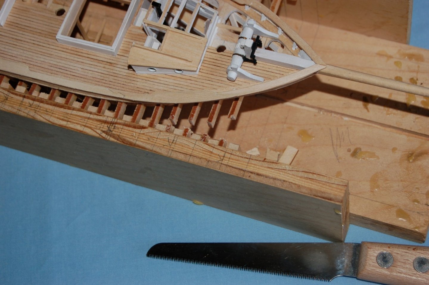


-
Been asleep for a while but your project is looking quite good. Re. missing pins? I assume you've considered the supplemental pin racks laced into the shroud lanyards re: p. 336 in Chapelle. This feature could give you eight additional pins per mast. These racks also show up in contemporary photographs eg. in Garland's Down to the Sea. "
- 86 replies
-
- 2
-
-
- schooner
- effie m morrisey
- (and 1 more)
-
Dove by jlefever - 1:48 - Pinky Schooner
jlefever replied to jlefever's topic in - Build logs for subjects built 1851 - 1900
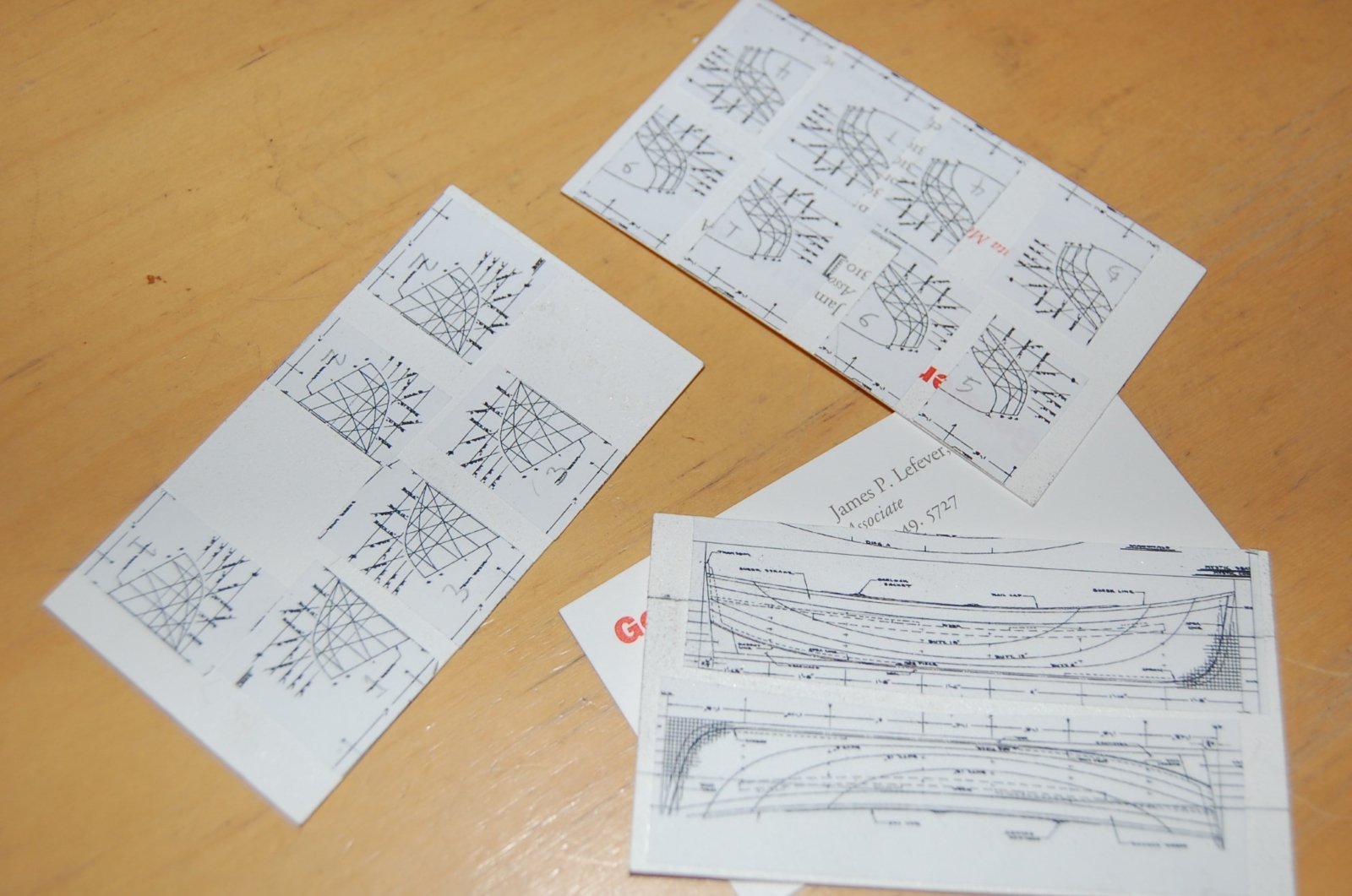
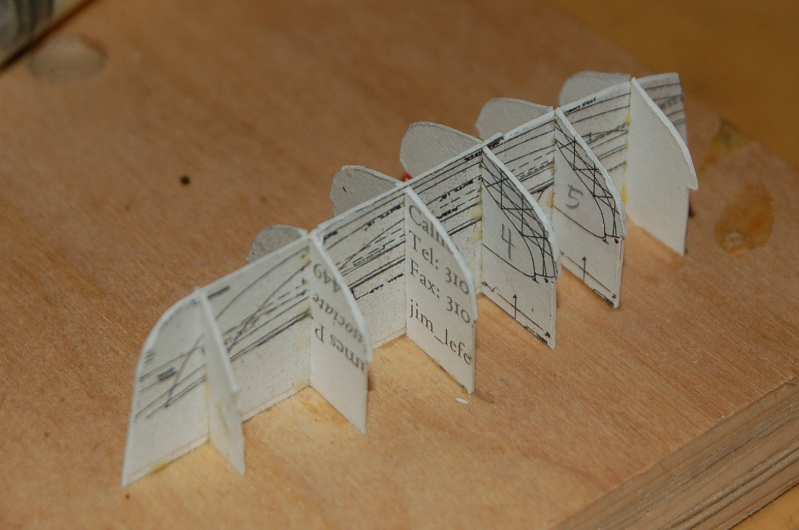
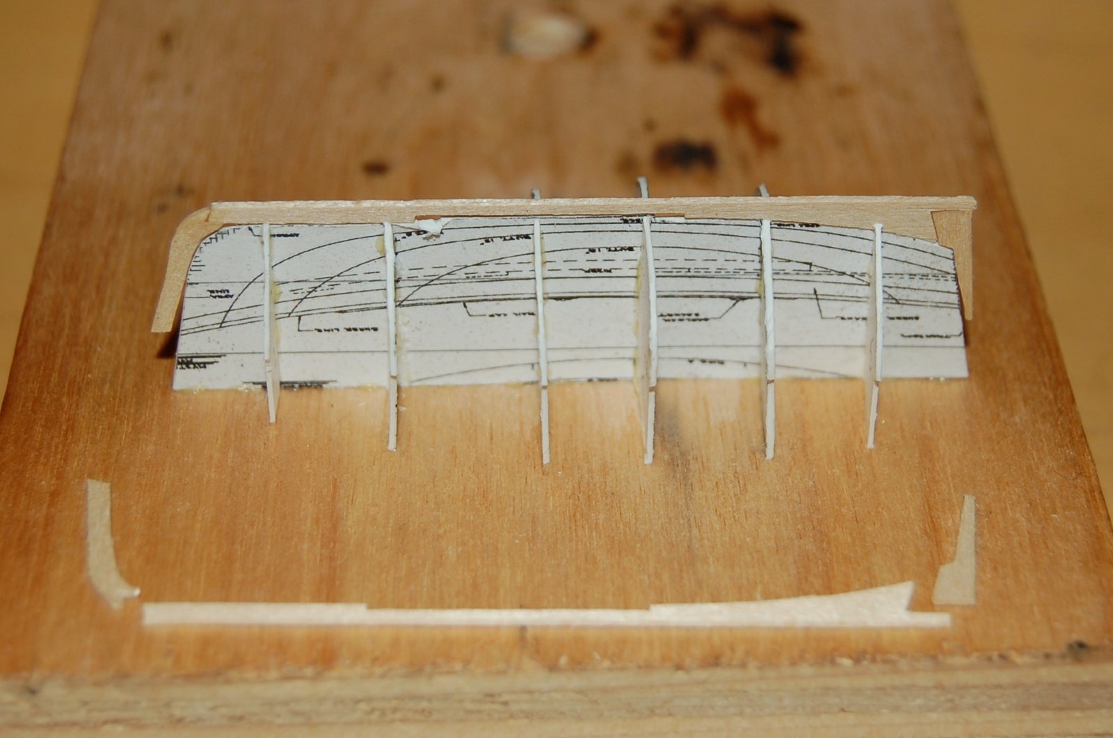
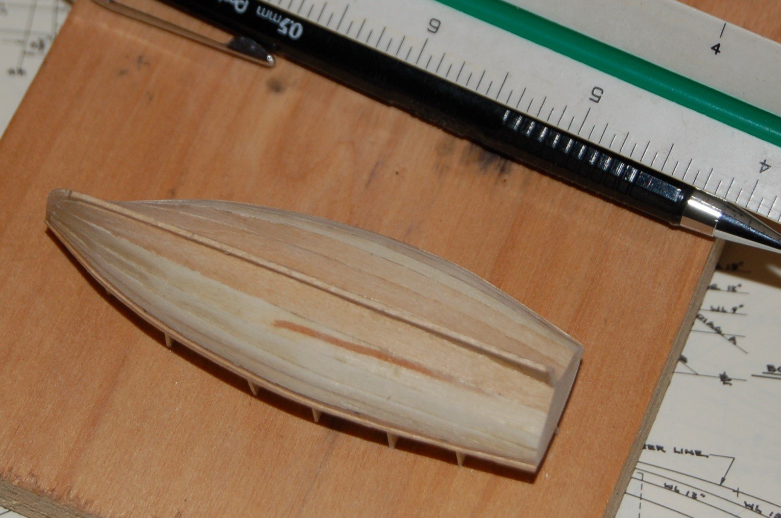
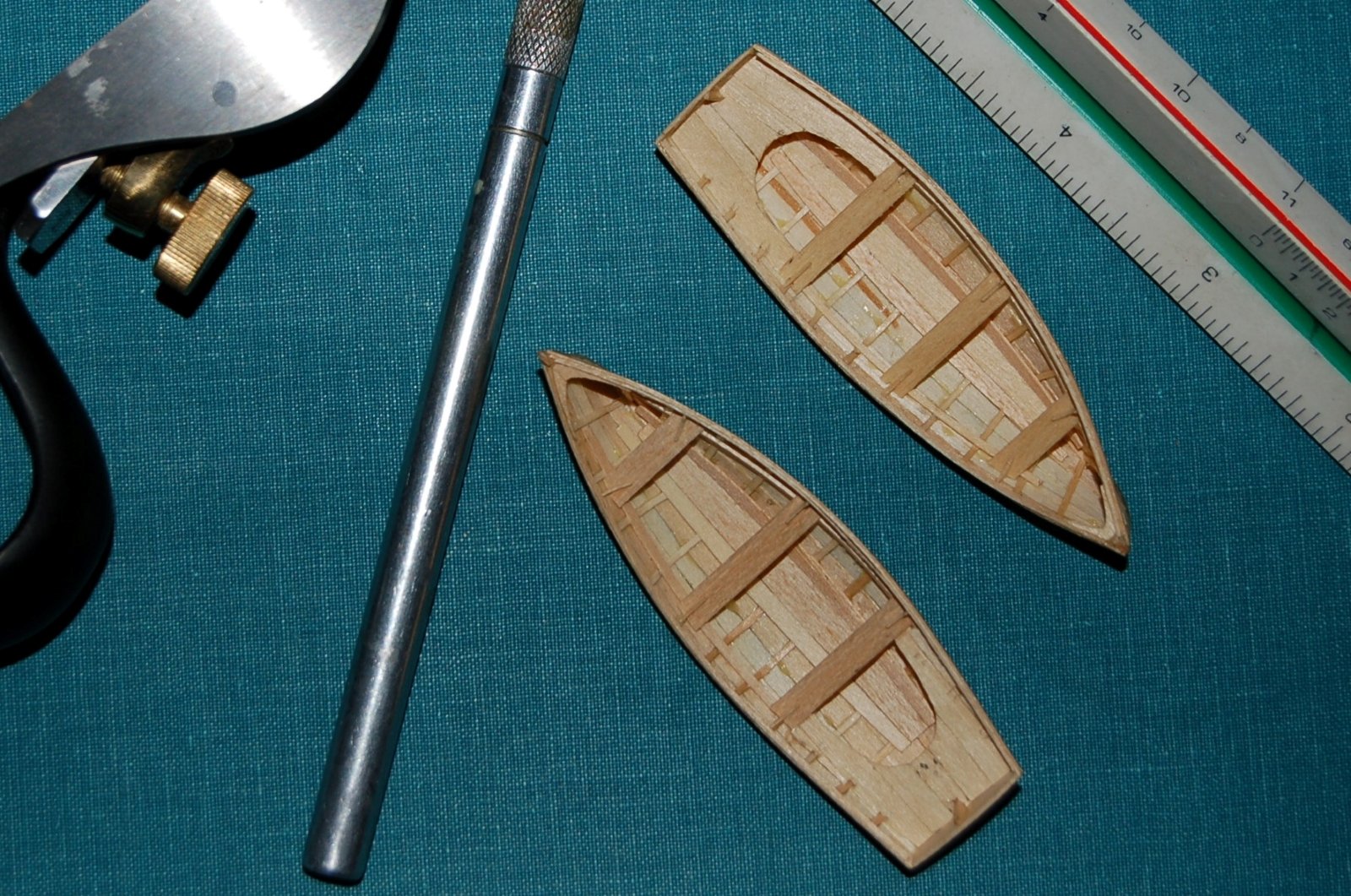
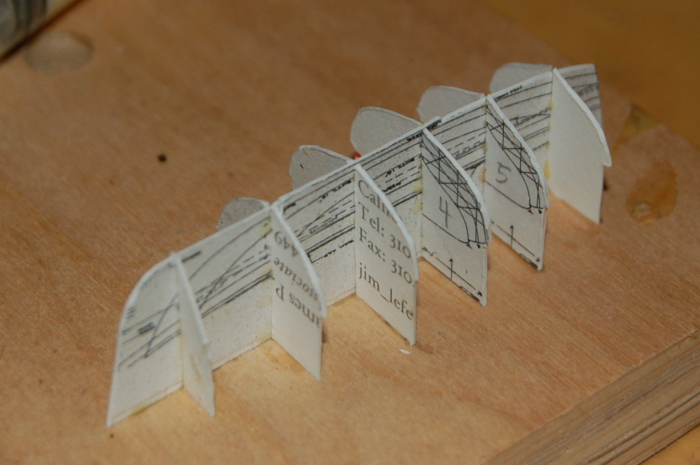
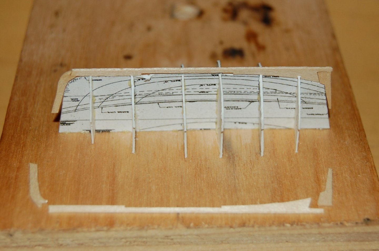
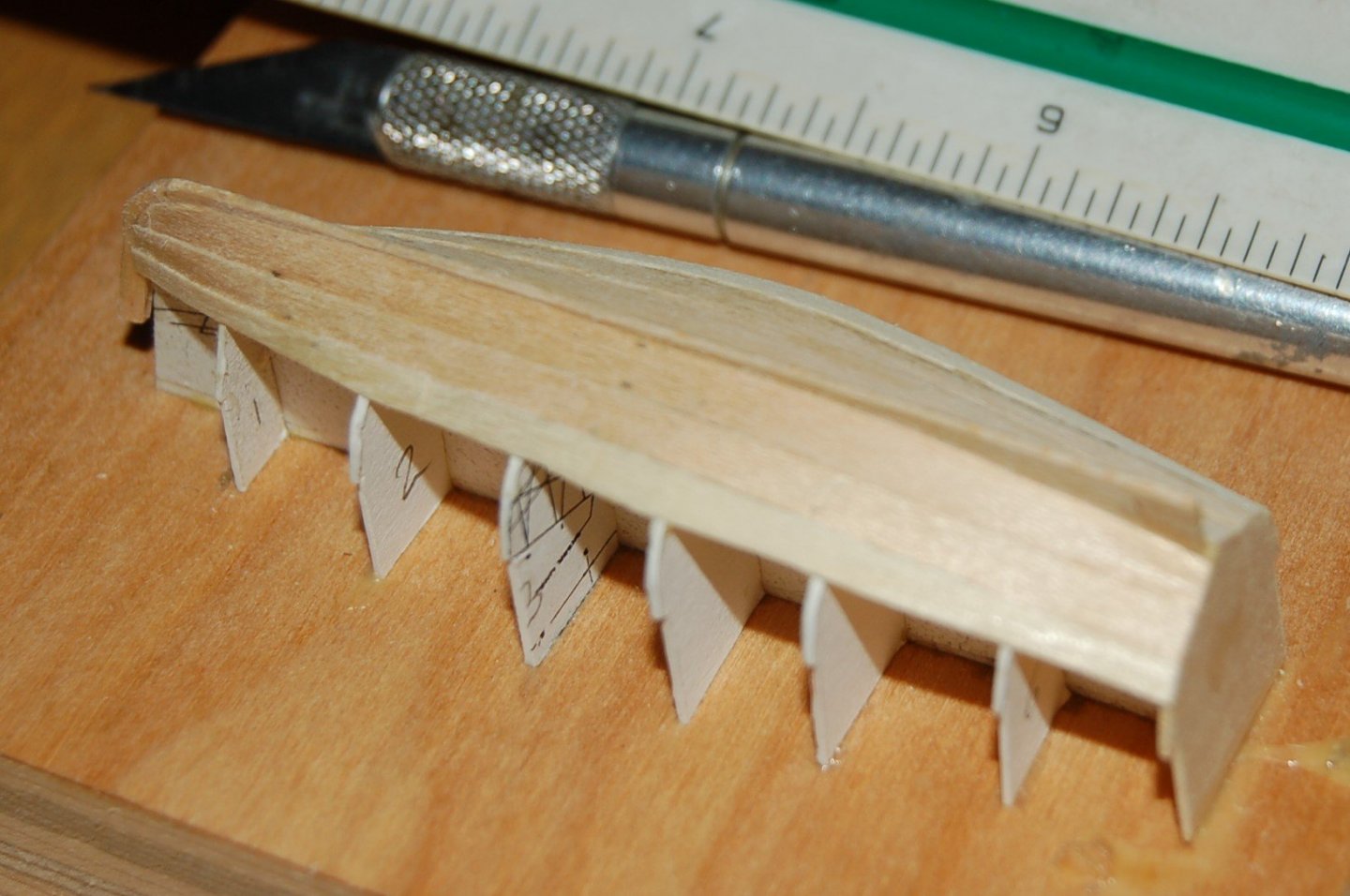
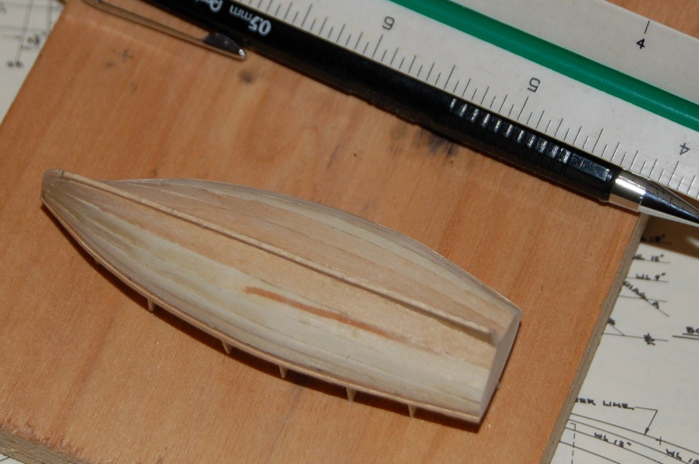
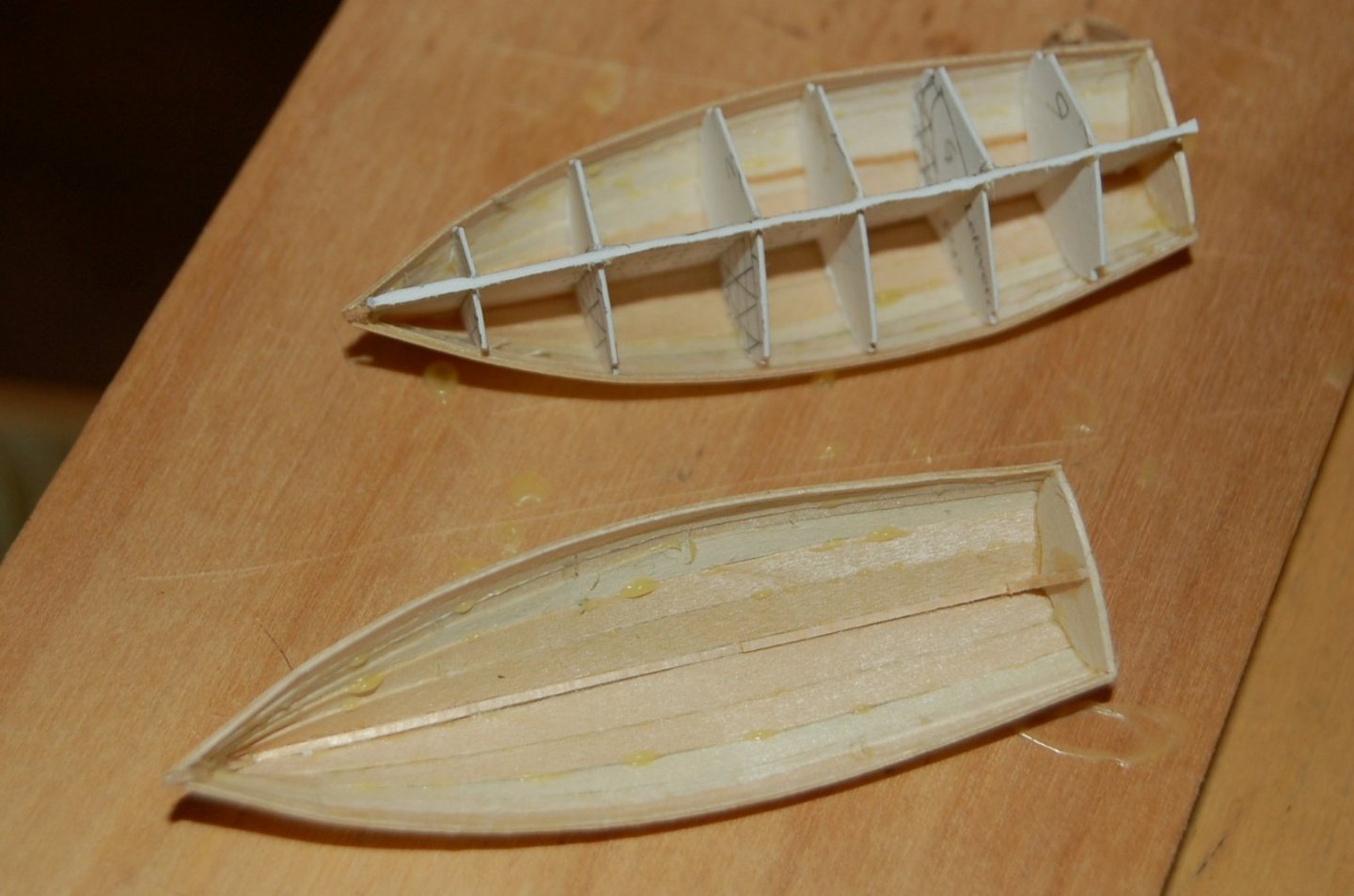
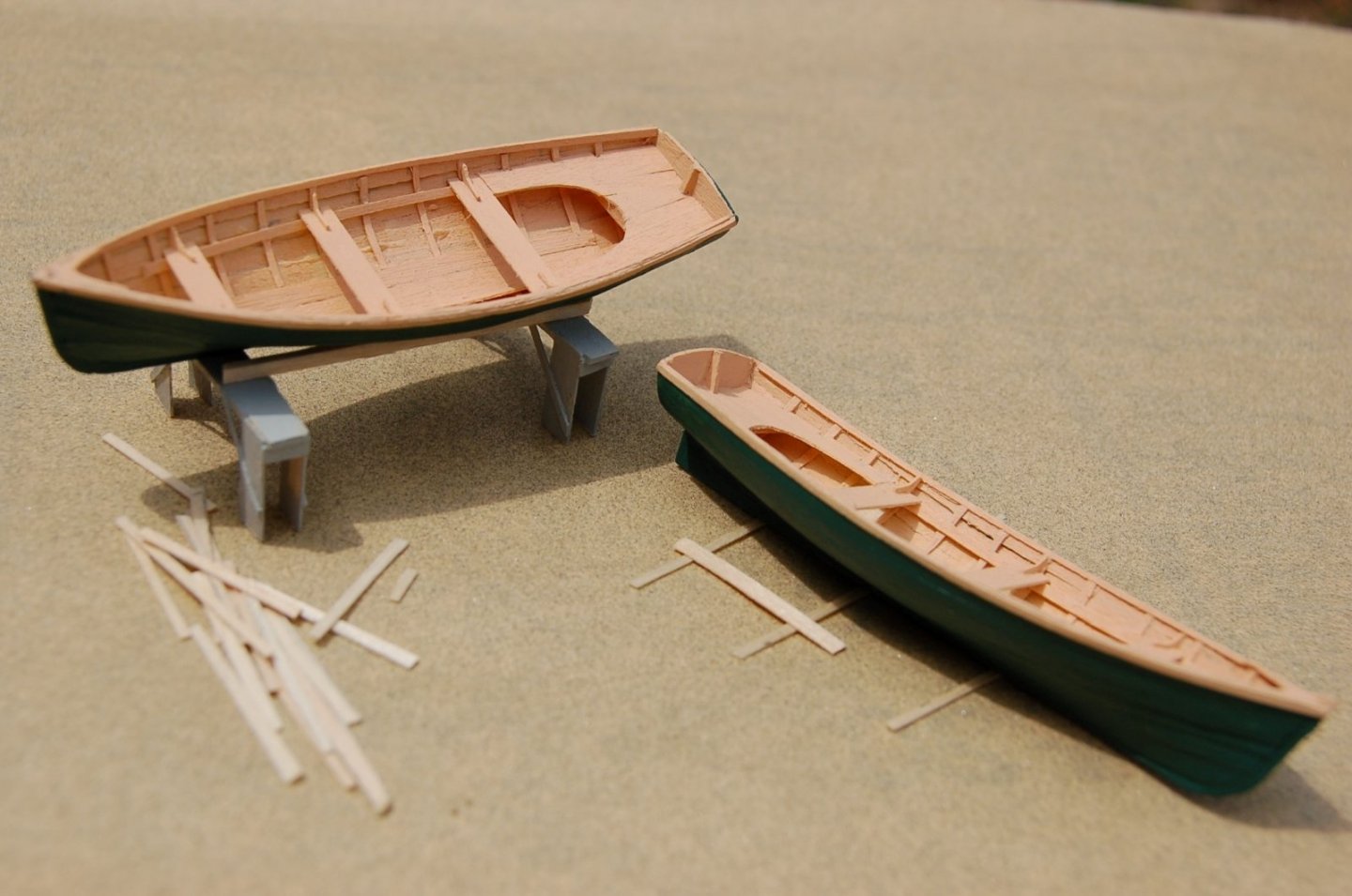
Mini Project 4 – The ship’s boat The next small project I took on was to create a ships boat for each of my Doves. Perhaps for a fisherman type schooner and for sea worthiness as well, the appropriate boat would be a dory. I’d already modeled a few dories and wanted to try something else besides a dory would be pretty big for such a diminutive vessel. From the book Watercraft by Maynard Bray describing the collection of the Mystic Seaport Museum I found the plans for an eleven-foot ten-inch Whitehall tender that looked to be both buildable and about the right size. With a little Xerox magic copies of the relevant plans were made, trimmed and spray mounted on a handful of old business cards. Figure 11‑15 - Plans for a Small Boat Plug for my model I made two copies, cut the various pieces out and glued them together on a spare piece of plywood. So, I guess, I did in the end include a plank on bulkhead model in my project. Figure 11‑16 - A plug from Business Cards Keel – A spine for my little boat In building these little boats I wanted to do my best to keep them to scale not only in the overall dimensions but also when selecting the thickness of my materials (while not always possible it is still a possibility at 1:48 scale). In many cases this meant that the woodwork was quite thin and even translucent. Ultimately, I would paint both the outside and inside of my boats to cope with this issue. Here are a handful of quite thin keel pieces (barely thicker than the cardstock) tacked to the plug with dabs of yellow glue. Figure 11‑17 - Boats Spine With the addition of a transom, I was ready to begin planking. Planking Starting from the keel and working both ways. This boat is caravel planked and thin as they are, each plank is quite flexible. They are edge glued and while I attempted to not get too much glue on the paper plug, I made no real attempt to protect the formers or prevent the glue from squeezing through the planks. Figure 11‑18 - Planking Well Underway Planked Here she is, planked to the rails and a whopping three inches long. Figure 11‑19 - First Boat Planked Unglued The paper “plugs” were throw-away elements so I simply took a scissors and snipped them off the plywood base. The edge glue used to secure the planking proved to be not much of a problem and the paper formers were soon worked loose leaving me with a solid and fairly clean shell. There were some glue dabs in the interior which I gently scrapped but in later images you will see that not all of the excess glue spots were cleared. They're more prominent when painted and in photography. Figure 11‑20 - Flipped Over and Ready to be Cleaned Fitted out for Rowing Here the little boats are seen with ribs, thwarts, floors, hooks, knees and stern sheets. All pretty thin material being basically made from wood planed down until it was nearly shavings. Three quarter inch thick wood scales to .015” thick at 1:48 scale. Figure 11‑21- Boat Interiors A light breeze will move these little models around. Finished Boats As promised, a little paint has cured the translucency issues. Figure 11‑22 - Watching the Paint Dry I still need to think about oars and oar locks but I’ve procrastinated long enough, it’s time to get on with the real modeling work with two of the most dramatic steps waiting in the wings. It’s time to cut the framed Dove free from its box and time to get on with planking both models. Once Again, Thanks for looking. Jim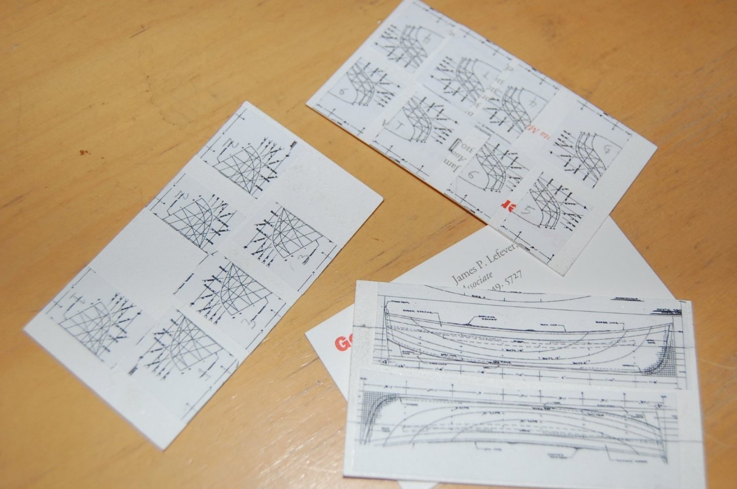

-
Dove by jlefever - 1:48 - Pinky Schooner
jlefever replied to jlefever's topic in - Build logs for subjects built 1851 - 1900
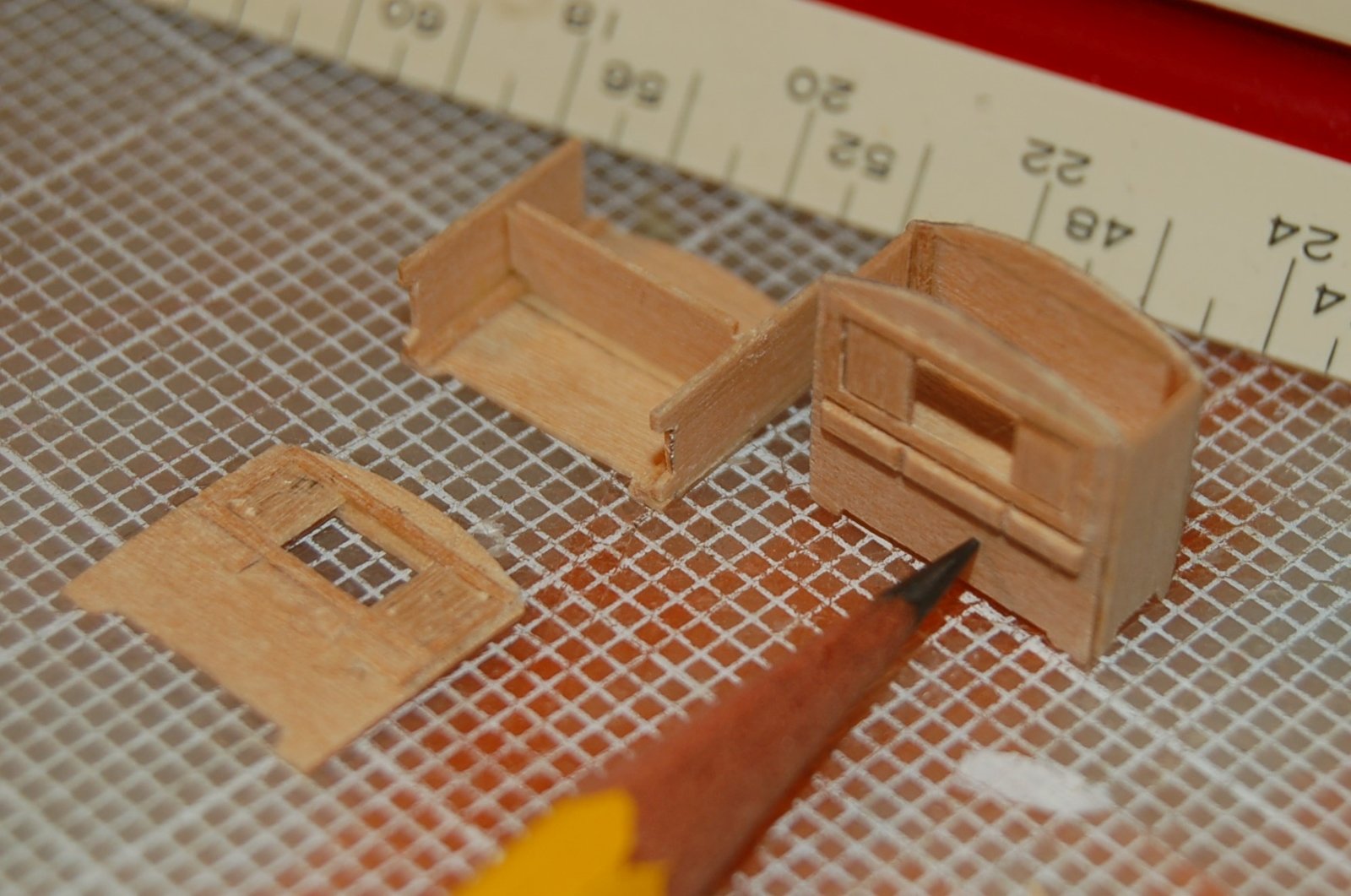
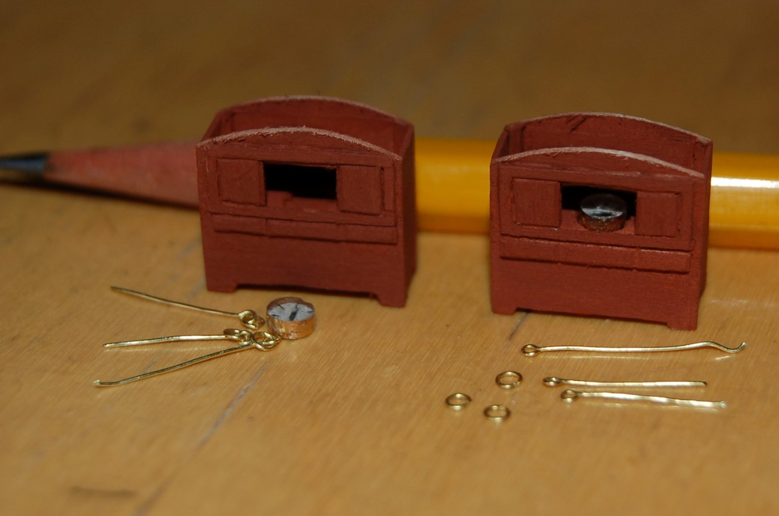
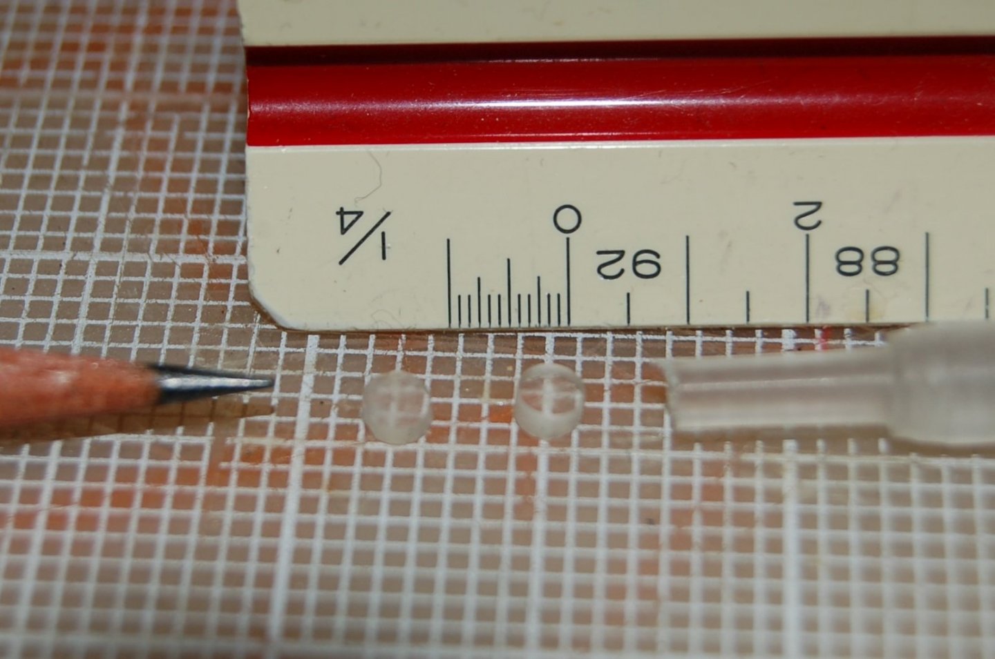
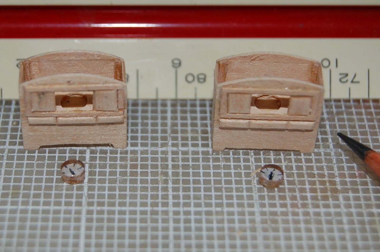
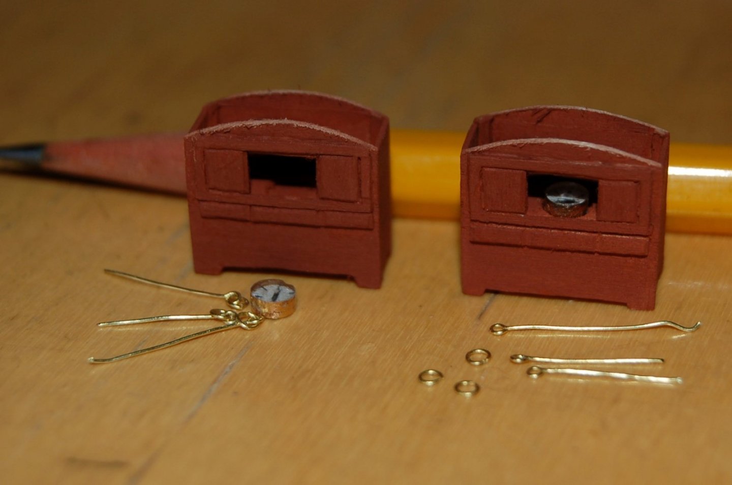
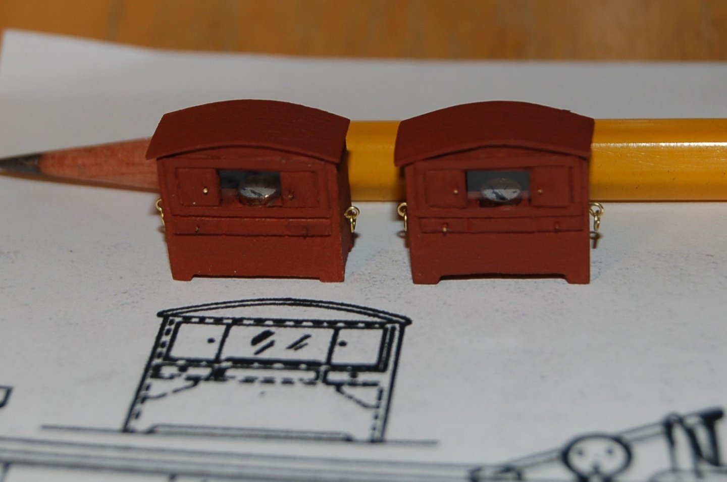
Mini Project 3 – The Binnacle Some projects are more fun than others. This was one of the more fun ones. It was small, short in duration and involved just a bit of creative thought. There wasn’t a plan for the Dove’s binnacle although the plans do include a partial side elevation of the case sitting just ahead of the tiller. Fortunately, I found a bit more information looking at the other pinky plans in Chapelle’s book which I used to “reconstruct” a binnacle for my Dove. It appears that in the case of vessels as small or old as the Dove, the binnacle was a smallish piece of cabinetry housing the compass and a light source that could be lashed to the deck when in use. I’m assuming in port the binnacle was stored below deck or simply removed to a safe location. I started with building up its tiny wood case. Figure 11‑10- Binnacle Case This little instrument was 2’-6” wide by 1’ deep and stood 2’-6” high. The actual cabinet is small, the model is tiny. Compass The Binnacle will be fitted with a six-inch diameter compass. Figure 11‑11 - Compass Blanks To create compasses for the Dove I started with a quarter inch acrylic rod and turned it down to an eight inch. The rod was sliced into small disks and the ends polished. The steps in making a compass model included: Paint the compass back white, etch a needle and compass points into the white paint, fill the etched lines with black paint, paint the sides with brass colored paint. The result six-inch diameter rough looking compasses. Figure 11‑12 - Ready to Mount Compasses Hardware The next step was to paint the cabinets, mount the compasses, glaze the opening with a thin acetate sheet and create hardware for ring and eye tiedowns. Figure 11‑13 - Binnacle Hardware I over achieved slightly. There’s only the need for two tie downs per cabinet. Finished The finished binnacles received an arched top and brass door and drawer pulls (short bits of brass wire) and acetate glazing. Figure 11‑14 - Binnacles Ready for the Sea I have one more "fun" project before I get back to work. That will come next. Jim
-
Looking really crisp and well thought out. Impressive. Jim
- 433 replies
-
- 6
-
-
- open boat
- small boat
- (and 1 more)
-
Dove by jlefever - 1:48 - Pinky Schooner
jlefever replied to jlefever's topic in - Build logs for subjects built 1851 - 1900
Thanks for the encouragement. I'll admit a bit of confusion on the length, Chapelle notes the length of the deck as 42'-11" and the plans give the same number as the length between perpendiculars. The load water line scales to about 39'- 1 1/2". Your question about the stern arrangement sent me of on a bit of a hunt but in the end I've come back to Chapelle. In his book American Sailing Craft he generally sees them as an American type becoming common in 1820 but perhaps with roots in Baltic and North sea traders. Of the stern he notes: "...the loss of it would not affect the seaworthiness..." and "The pink stern was not put on for looks..." He suggests as practical reasons to protect the helmsman and rudder, support the mainsheet horse, act as a seat of ease, to hang nets and a crotch for the main boom. Now that you mention it, it does look somewhat Asian... Jim -
Dove by jlefever - 1:48 - Pinky Schooner
jlefever replied to jlefever's topic in - Build logs for subjects built 1851 - 1900
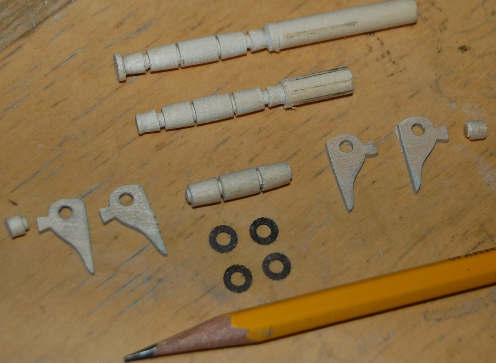
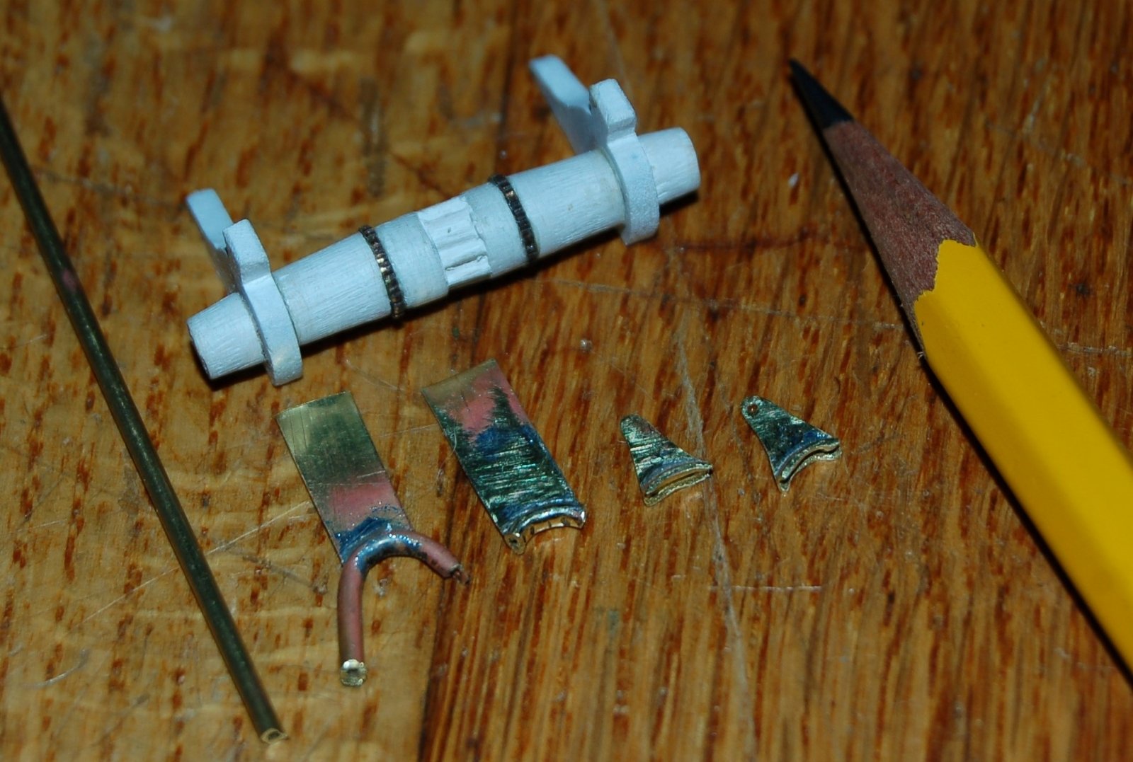
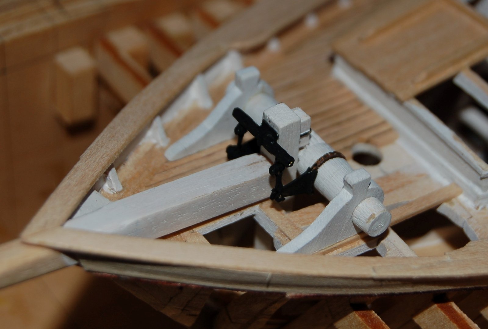
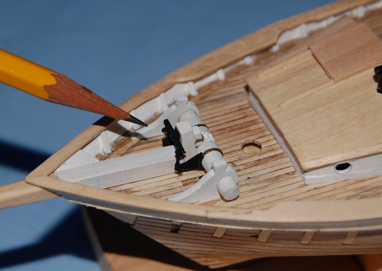
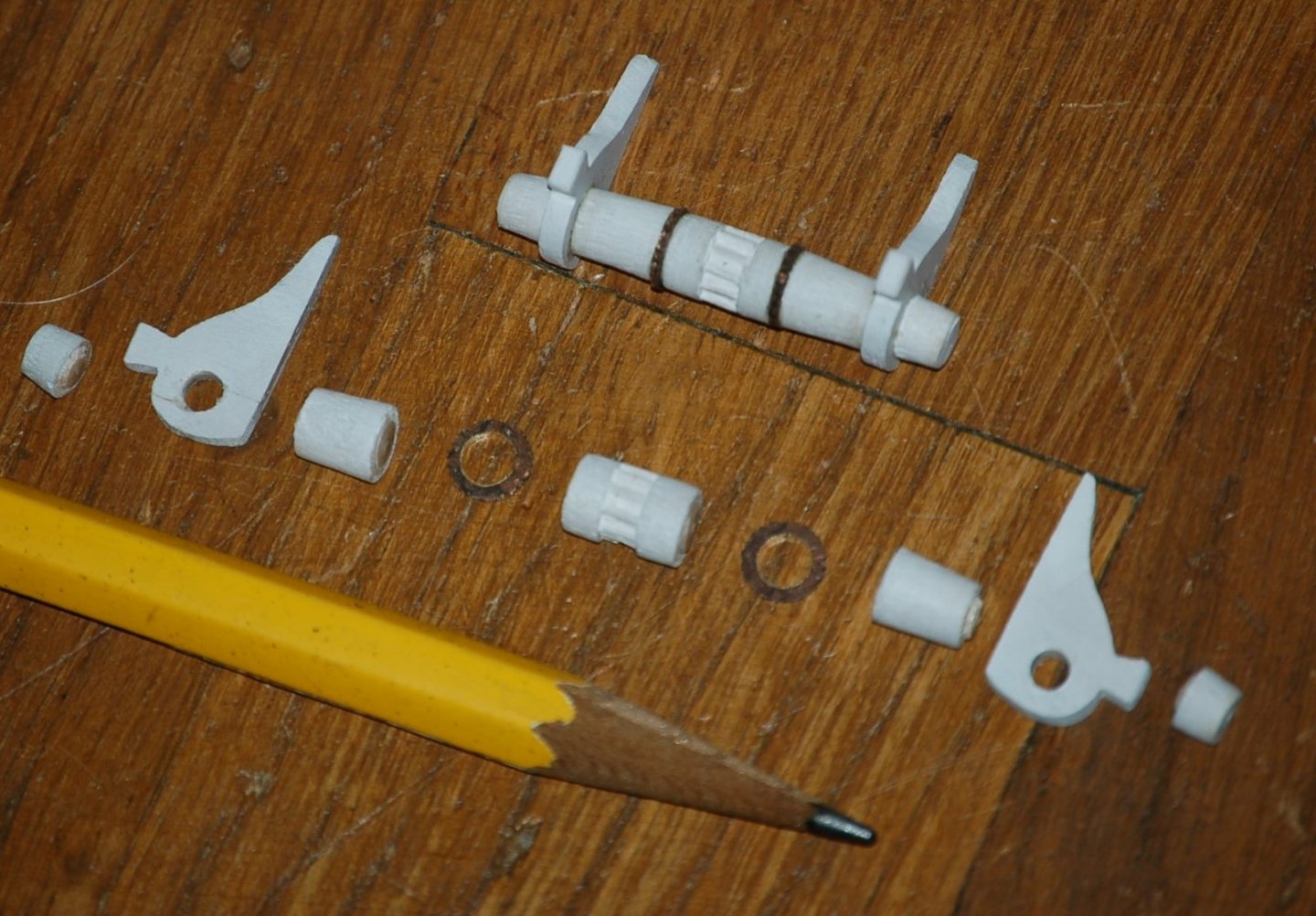
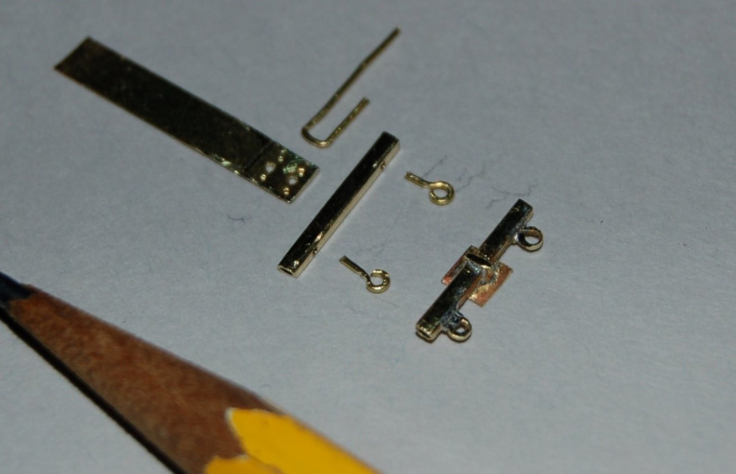
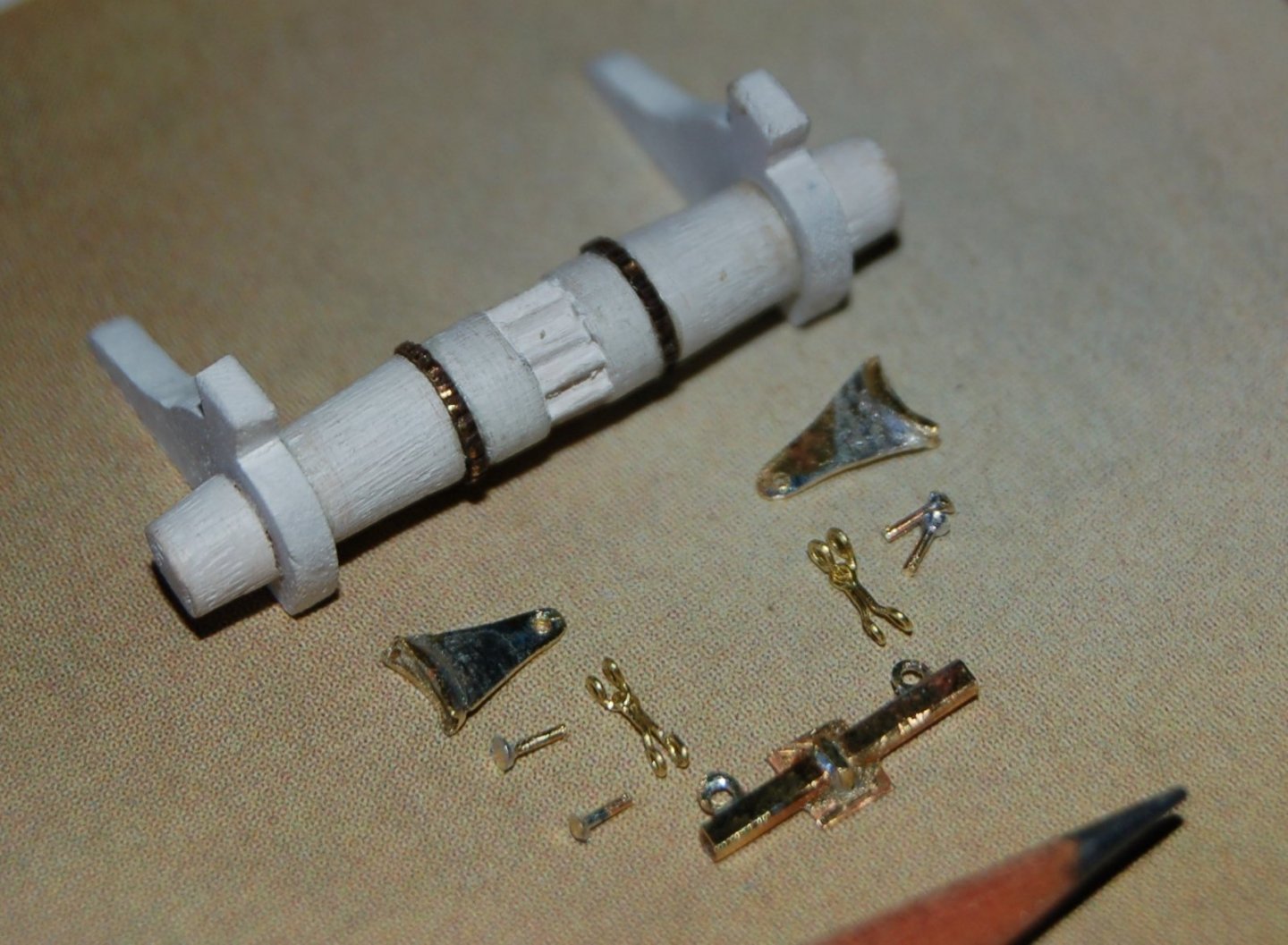
1.1 Mini Project 2 – Windlass The Dove plans show limited details on the windlass. Here’s what I see on the plans: The framing plan locates the windless bits and gives a profile for the barrel of the windless. The section shows the pawl post (king post) supporting the bow sprit and holding the windless pawl block with what appears to be a heavy staple. The sheer plan adds a bit of detail showing the attachment of the rocker assembly at the forward top of the pawl post. While there is no other plan information, I assumed this indicated the presence of a pump break type windless mechanism. I’ve based my model on that assumption. Beginning in the 1850’s fishing schooners and similar vessels began to use a pump break windlass. Essentially this type of windlass featured a rotation ratchet assembly (purchase ring and arms) driven by a rocker and brake levers much like those used to power old railroad handcars. Here’s how I approached modeling the Dove’s windlass. To make the windlass barrel, I chucked a dowel into my drill press and turned it using files and hobby saws. The bits were simply traced drilled and carved from sheet stock while the purchase rings (toothed metal rings used to rotate the barrel with a ratcheting action) were creating from brass washers into which teeth have been filed. Figure 11‑3 - Windlass Parts While it certainly isn’t the way a real windlass would be built, I elected to slice up my windlass barrel allowing me to fit the purchase rings and main bits over the barrel with some precision. Here’s one cut apart and a second glued back together. Figure 11‑4 - Windlass Barrel Assembly At the center of the barrel, notches have been chiseled into the wood. In actual practice these notches engage a sliding pawl attached to the pawl bit to prevent the barrel from spinning in reverse while it is under load. Purchase Arm Each Windlass requires two purchase arms. These are the levers that ride along the purchase rings turning it a notch at a time as they are lifted by links to the rocker above. To form the purchase arms (in reality fashioned from cast iron) I started by soldering a bent section of fine brass tubing to a tab of sheet brass. Using a grinder bit in a rotary tool and hand files half the tube was cut away leaving a semi-circular channel attached to the brass tab. The tab and channel were further hand shaped to approximate the shape of the purchase arm before, finally, a small hole was drilled in the tab to accept the link from the rocker. Figure 11‑5 - Forming the Purchase Arms Rocker Assembly The Rocker assembly consists of rocker bearing, an iron plate which will be bolted to the kingpost. The bearing includes a pivot axle which supports the rocker. The rocker has a pair of eyes which will carry links to the purchase arms fashioned above. Figure 11‑6 - Building the Rocker Assembly To model the Dove’s rocker assembly, I started with a tab of sheet brass, drilled it to accept a brass wire U and embossed it to simulate bolt holes. The rocker was created from a piece of brass tubing flattened and filed to create a rectangular section. A pair of brass eyes were soldered into holes in the bottom of the rocker. The whole assembly was then soldered together and snipped off the brass tab. A lot of detail is missing on these parts but they are quite small and will be painted black. Connecting the rocker to the purchase arms were a pair of suspended links that in turn loop through a shackle bolted through the hole in the purchase arm. Figure 11‑7 - Connecting Links and Bolts The links and shackles were fashioned out of brass wire as were the bolts that connect it all together. At this point, I was definitely improving my soldering skill set. Windlass Installed Here’s a Windlass mounted on the bow of the framed Dove. Figure 11‑8 - Framed Dove's Windlass And here is its mate, Installed on the solid hull Dove. Figure 11‑9 - On the Solid Hull Dove Clearly between the sharp bow, the mast and the cabin trunk, there wasn’t a lot of space to work the Windlass. I’m assuming the anchor, or anchors, would be lashed to the bow and the cable unshipped and stored below. My next small project will be building a binnacle for the Dove’s.


-
You are making great progress. It's interesting seeing how your work attacks problems current to all of us finding a variety of approaches to creating similar models. Your approach seems both accurate and eminently reasonable. I'm continuing to follow with keen interest. Jim