HOLIDAY DONATION DRIVE - SUPPORT MSW - DO YOUR PART TO KEEP THIS GREAT FORUM GOING! (Only 20 donations so far - C'mon guys!)
×


FriedClams
-
Posts
1,368 -
Joined
-
Last visited
Content Type
Profiles
Forums
Gallery
Events
Everything posted by FriedClams
-
 Fantastic work, Grant! She turned out great. Congratulations on its completion. Gary
 -
Excellent - another river boat and a great start, Eric. A terrific new workspace too! Will be following along with interest. Gary
-
The head repositioning is artistry, Marc. Not so much the mechanical act of it, but in visualizing what needed to be done. Gary
- 2,696 replies
-
- 3
-

-

-
- heller
- soleil royal
- (and 9 more)
-
If you haven't already, check your local hardware/building supply outlets as this sort of tape is often used on sheet metal ductwork to prevent air leaks. Varying widths and possibly thicknesses. Excellent (and fast) progress on your model, Nils! Gary
-
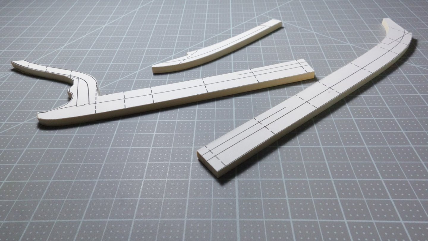
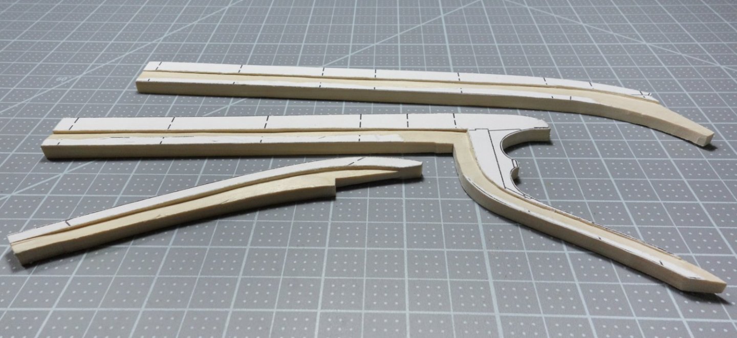
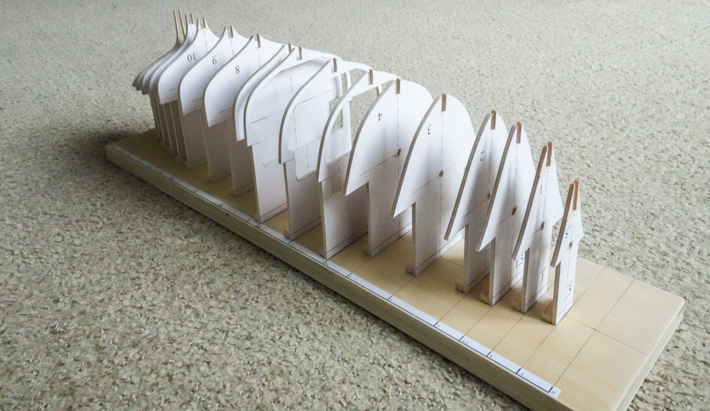
Greetings, Here's the current state of the model. The backbone drawing template was printed out in three sections onto full sheet label paper. The wood for the backbone is poplar and was cut to the required thickness using my full sized table saw. The templates were affixed to the poplar and cut out with a scroll saw. The rabbet was then carved into both sides. Below, the backbone is sitting temporarily on the station forms, waiting to be permanently attached. This model is being placed on temporary hold and it will be some time before I post again. I thank all of you for your interest in it and I hope to report some progress by the end of the year. Thanks. Stay well. Gary

-
A great start to another creative and interesting build, Glen! Looking forward to following along. Gary
- 290 replies
-
- 3
-
-
- Quinquereme
- Finished
- (and 1 more)
-
Sad to hear of your heart attack and so glad to hear of your recovery, Michael. It's great to see (and marvel) at your wonderful work once again. You have been missed. Welcome back. Gary
-
Nicely done, Mark - she looks great! Congratulations on completing her. Gary
- 505 replies
-
- 6
-
-
-
- vanguard models
- Sphinx
- (and 1 more)
-
Just went through your log and what an amazing build. Superb work, congrats on finishing her. Gary
-
Another miniature marvel in progress. Good to hear from you, Patrick. Gary
-
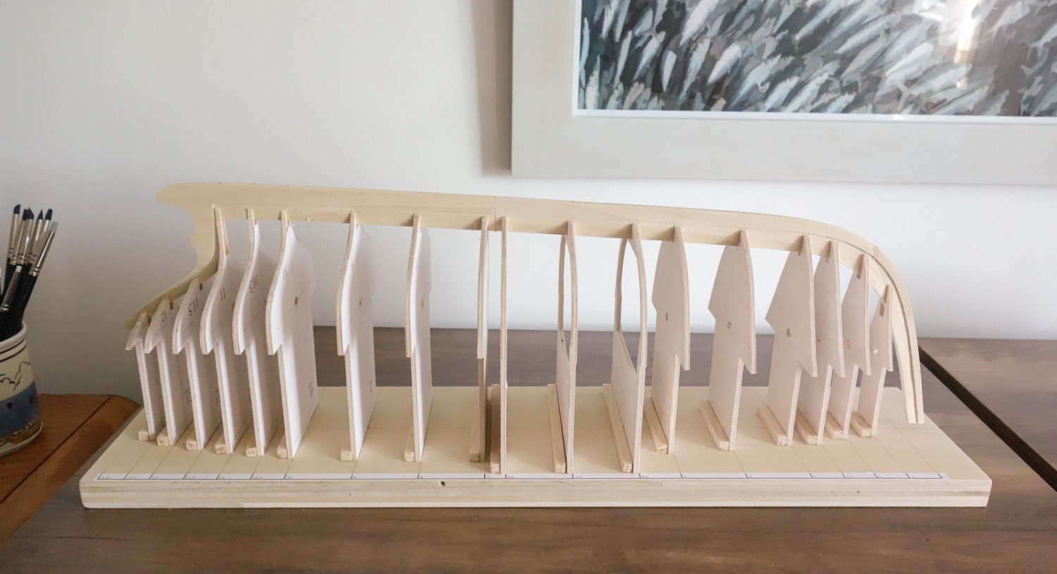
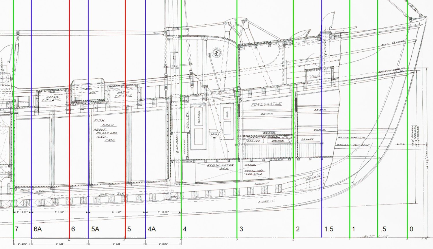
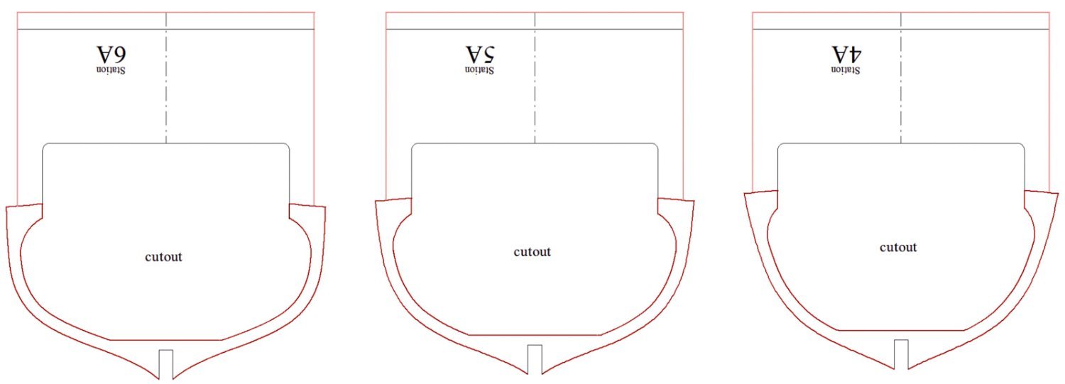
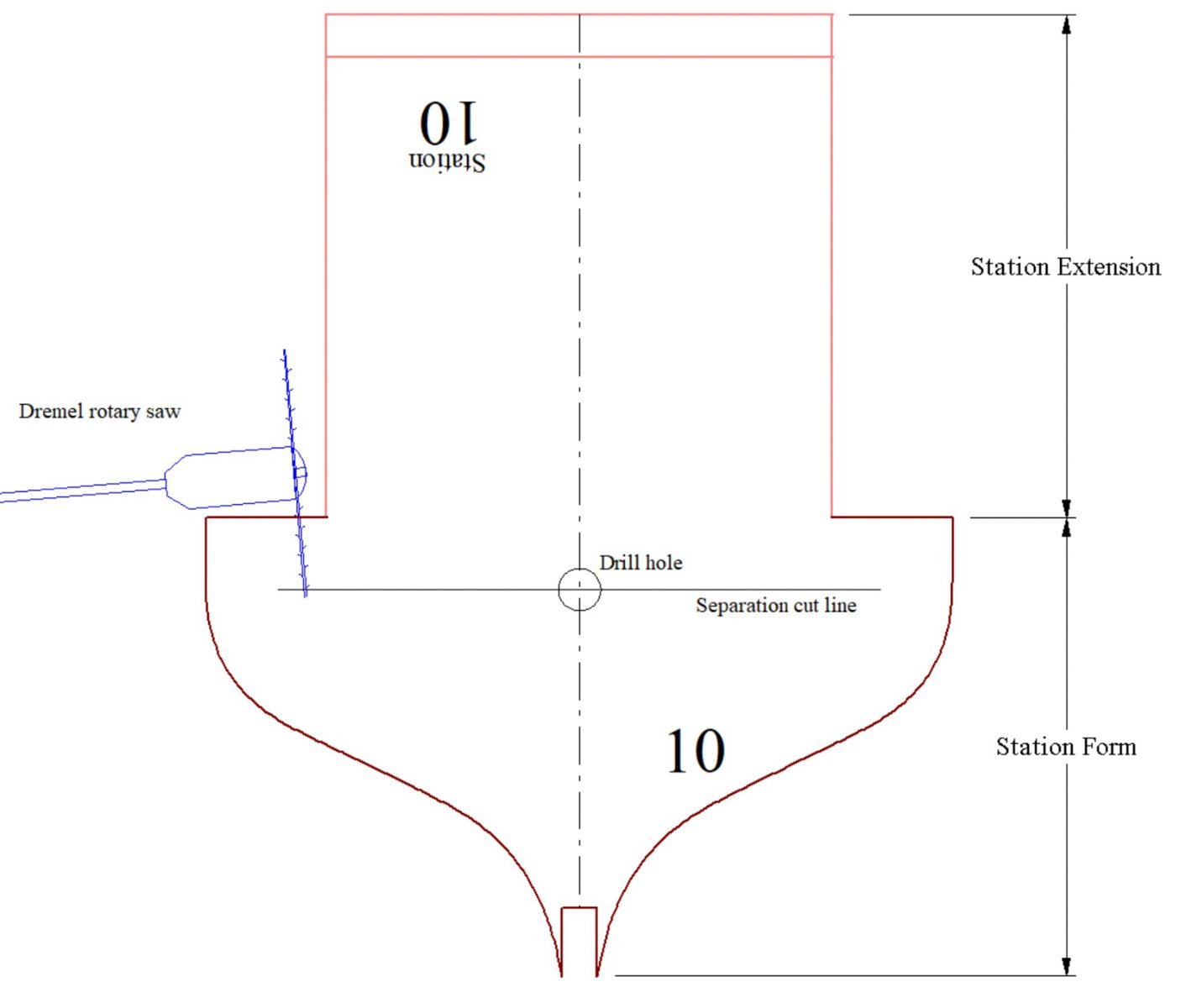
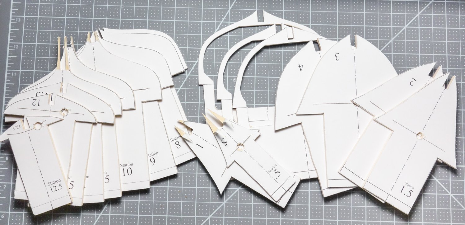
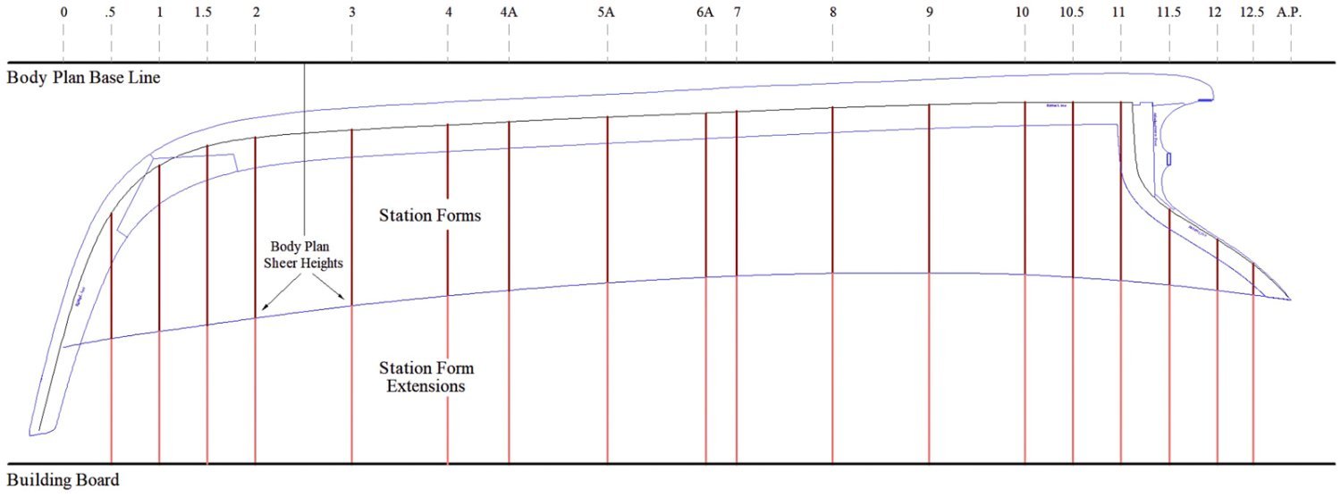
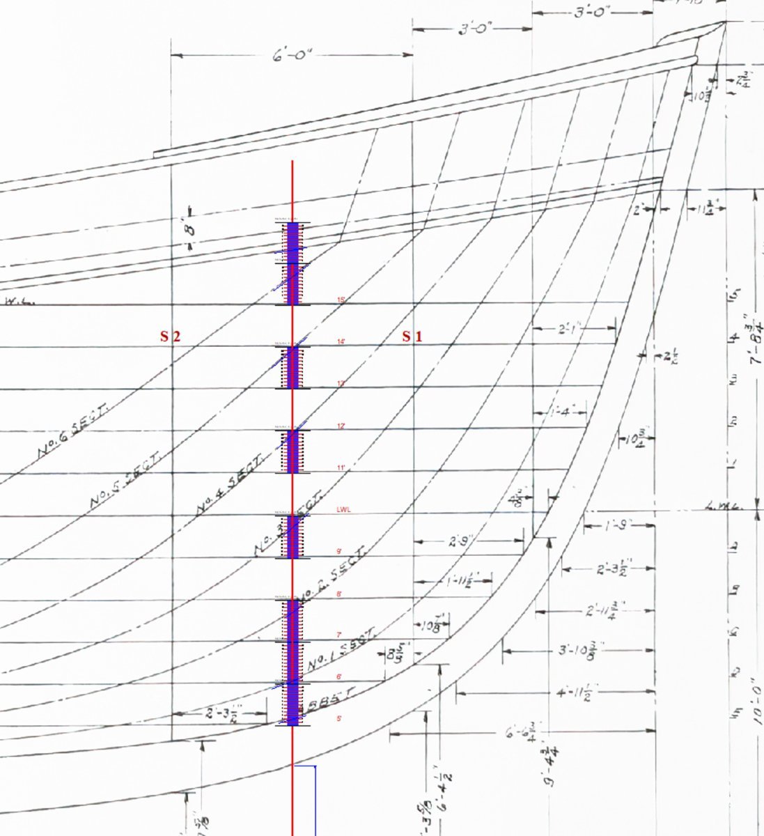
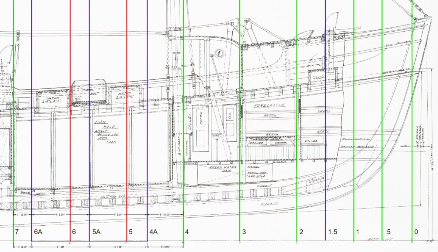
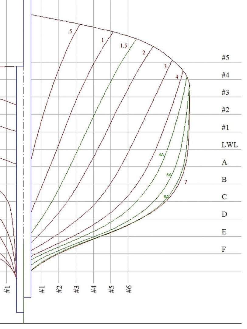
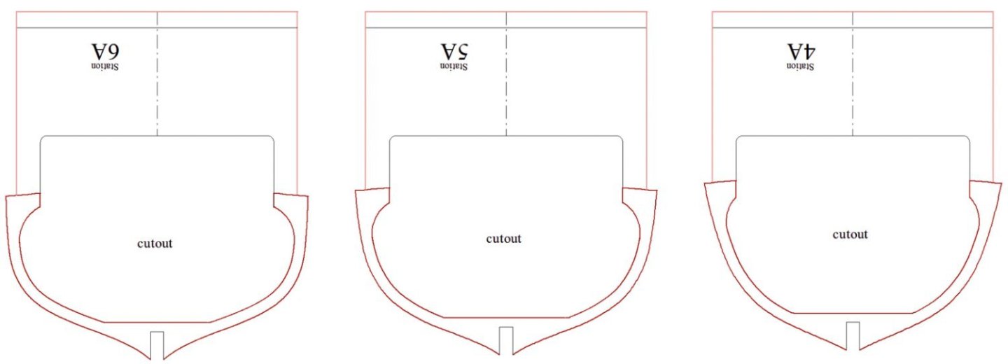
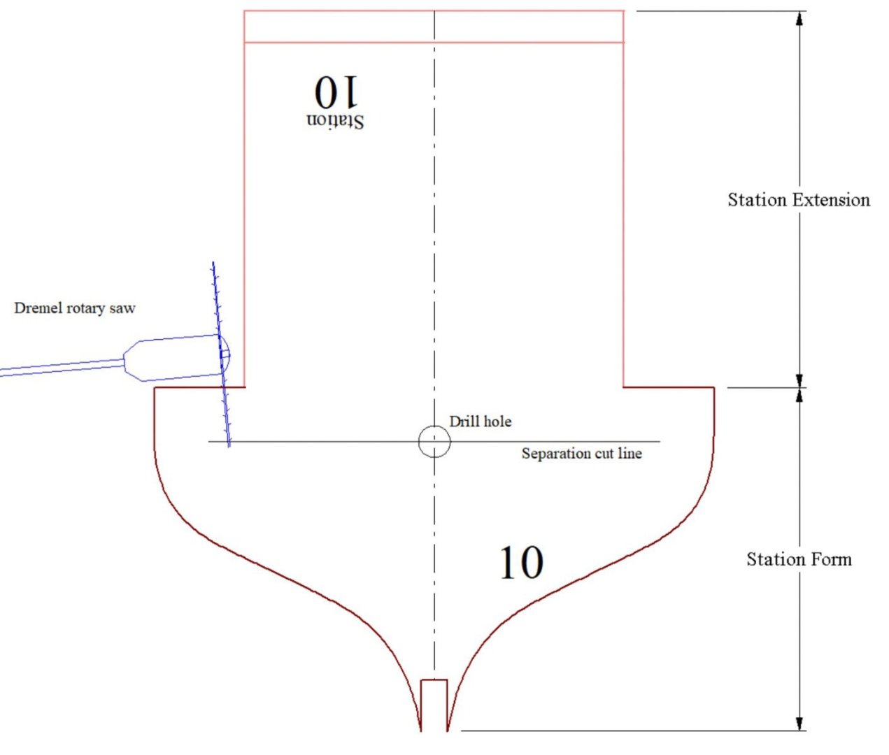
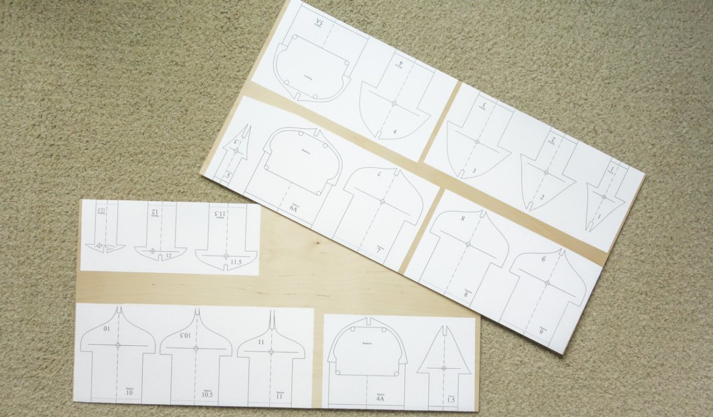
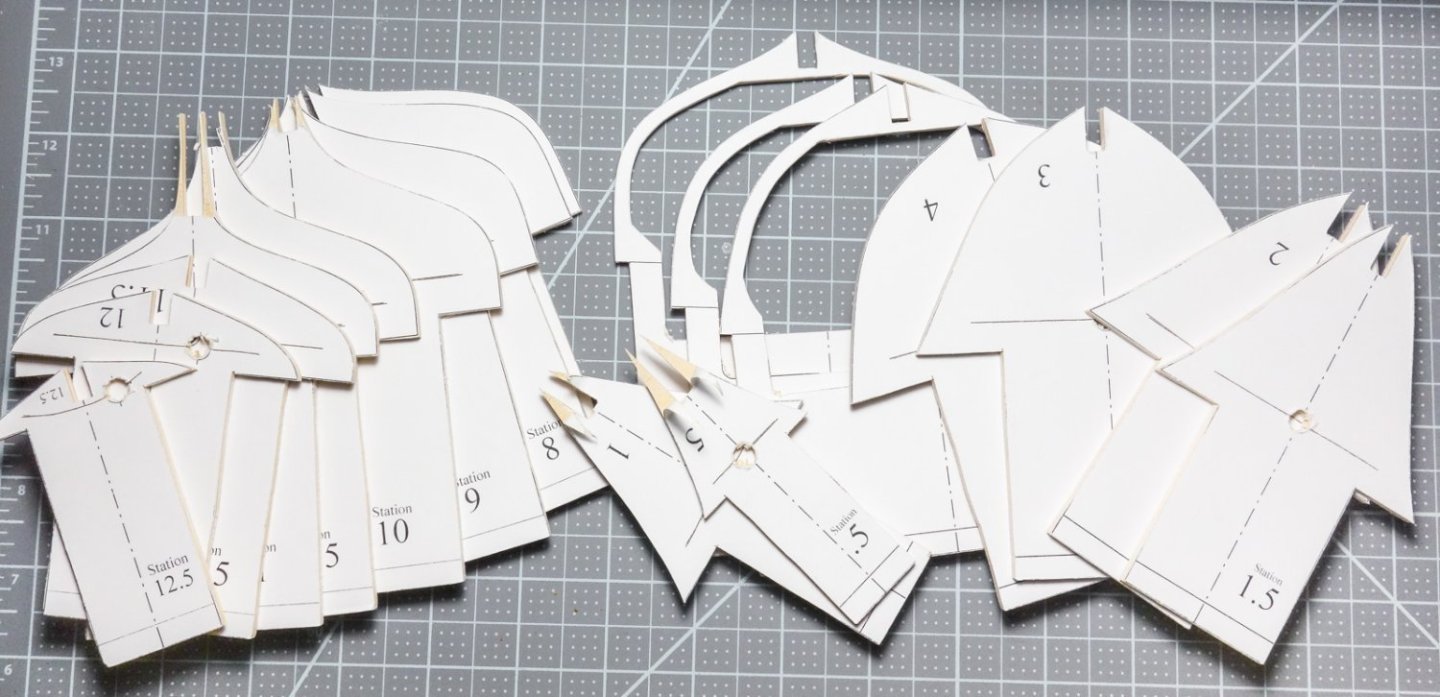
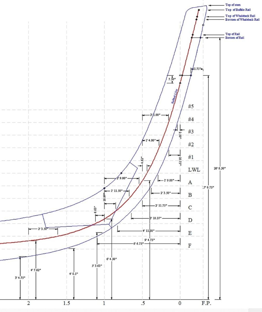
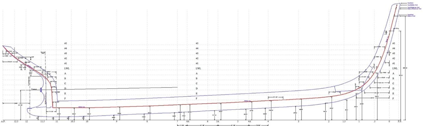
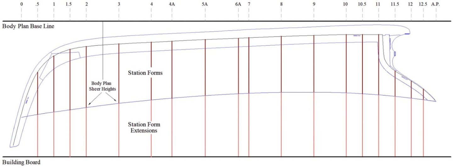
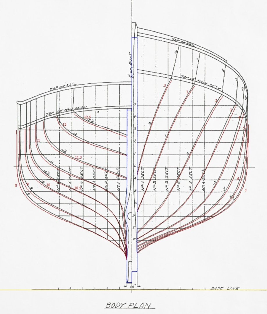
Greetings all and thanks for the kind comments and the "likes". Before moving on to the backbone, the station curves on the body plan need to be completed and developed into station bulkhead form patterns, printed, cut from plywood and finally arranged on a building baseboard. The model will be displayed with the fish hatches open and probably a bunker plate removed to allow a peek into the dimly lit partitioned hold below. The positioning and spacing of the stations as indicated on the original plans are provided only to define the shape of the hull and of course, do not reference any structural element. But because I'm using those stations as bulkhead locations, where they land within the fish hold area is of consequence. As luck would have it, station # 5 intersects the forward hatch and #6 lands on a coaming timber at the aft hatch. So those stations needed to be removed and three new modified stations added in replacement. In the drawing below, the vertical red lines are the removed stations #5 and 6. The blue lines are the replacement stations 4A, 5A and 6A, which as you can see do not interfere with the hatch openings and will provide a landing spot for the hold outer wall planking. Body plan curves for three new stations were generated from the "lines" drawing in the same way station #1.5 was done in my previous post. Stations #5 and 6 were removed from the body plan and 4A, 5A and 6A were added. The added station forms were hollowed out to the width determined by the hull framing at each cross section. Deck beams will eventually strengthen these openings and be installed after the form extensions are cut from the hull and the fish hold is planked and partitioned. The remainder of the station bulkhead forms were then drawn up. Each one has a drill hole mark and separation cut line that will allow the forms to be detached from their extensions once the hull is fully planked. One end of the scroll saw blade will be inserted through the drilled-out hole and used to cut along the separation line. A Dremel rotary saw will be used to make the final separation. I printed the forms on full sheet adhesive labels and affixed them to two 12” x 24” sheets of 1/8” craft plywood taking advantage of the factory cut edge. Scroll sawed, filed and sanded. Attached to the baseboard. Next came the backbone drawings. The original plans show very detailed dimensioning describing the shape of these timbers, so it was mostly just an exercise of re-plotting this data onto a newly created grid. Rather than tracing an imported CAD image, I took this extra step because I already knew the original photocopies were slightly skewed and the import process would have only exaggerated the problem. Here's how the backbone will sit on the station forms shown in profile. Before I physically cut and assemble the backbone, I'll make a cardboard mock-up and test fit it to the forms. It would be beyond irritating to say nothing of embarrassing to spend hours carefully making a backbone that doesn't quite fit because I botched the drawing. I look forward to the end of this preliminary work and to begin actually building the model. Be safe and stay well. Gary

-
Congratulations Andrew - she looks great - very nicely done! Gary
-
Wonderful brass work as always, Valeriy! Small, but efficient looking shop. Nice. Gary
-
Sort of a wood/card hybrid. Always enjoy watching your progress on these card models, Chris. Gary
-
Nice work Jeff! I particularly like the finial rust staining running down the roof valleys and the subtle rust coloration below the stove smoke jack. The roof patches are a convincing addition also. It’s the details that keeps a viewer looking. Gary
-
US 6” gun by RGL - FINISHED - Panzer Concepts
FriedClams replied to RGL's topic in Non-ship/categorised builds
Beautiful work Greg - exceptional paint and weathering. Gary -
Interesting subject, Nils. I well remember your Kaiser Wilhelm der Grosse build and I look forward to following this new project of yours. Gary
-
Thanks, Roger Ok, Keith and Mark - why are you guys yanking my chain? I’ve been following both of you and your wonderful work for several years now and I haven’t seen any of this hacking you speak of. Your work is top notch. You both are always kind, helpful and supportive to so many of us here at MSW, and a true credit to the forum. And certainly not hacks. Gary
-
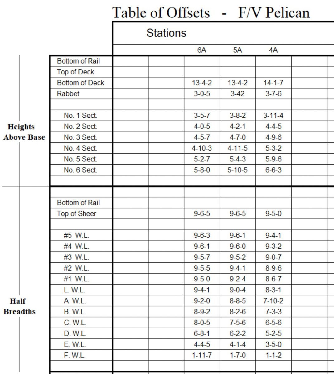
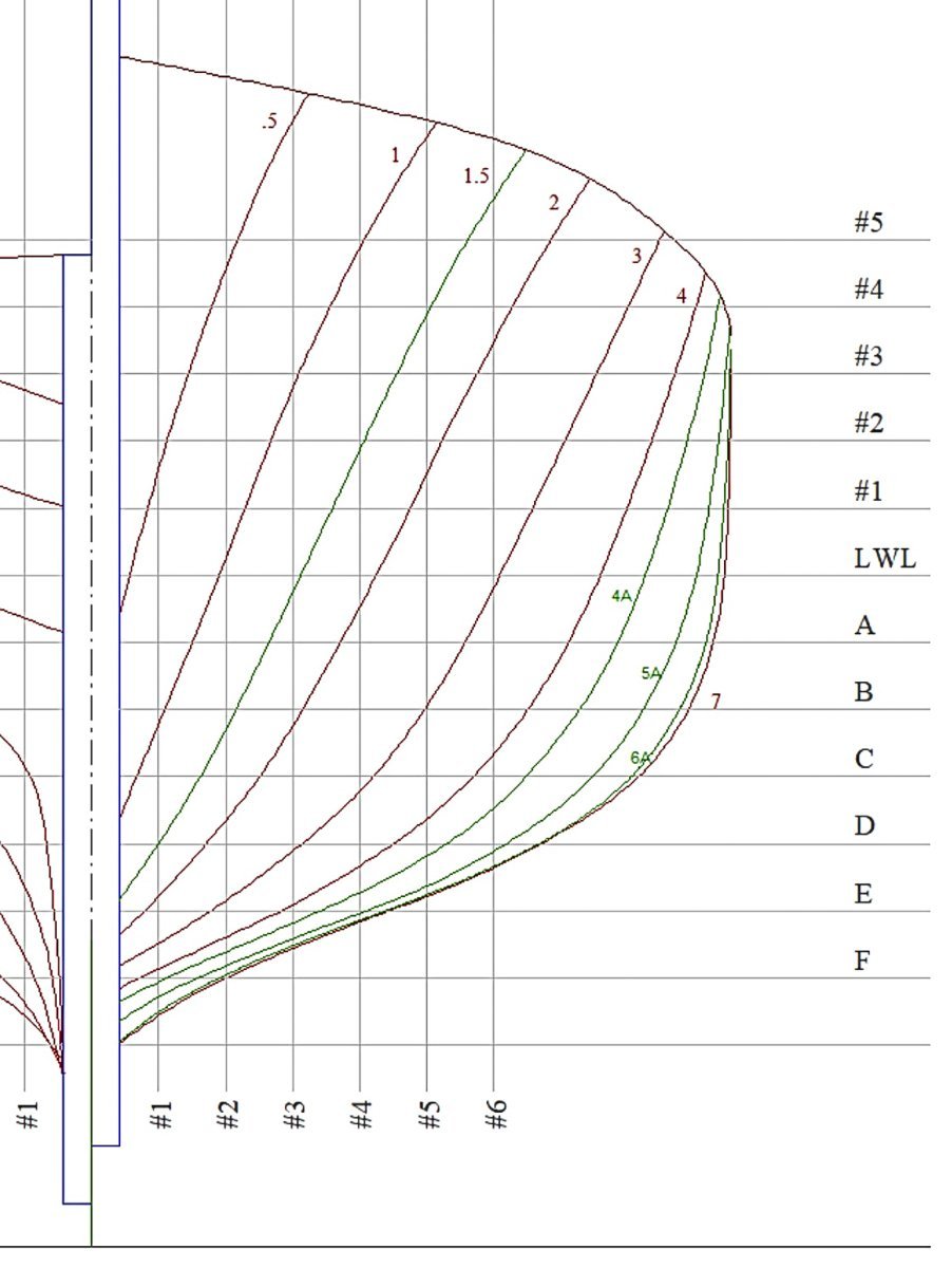
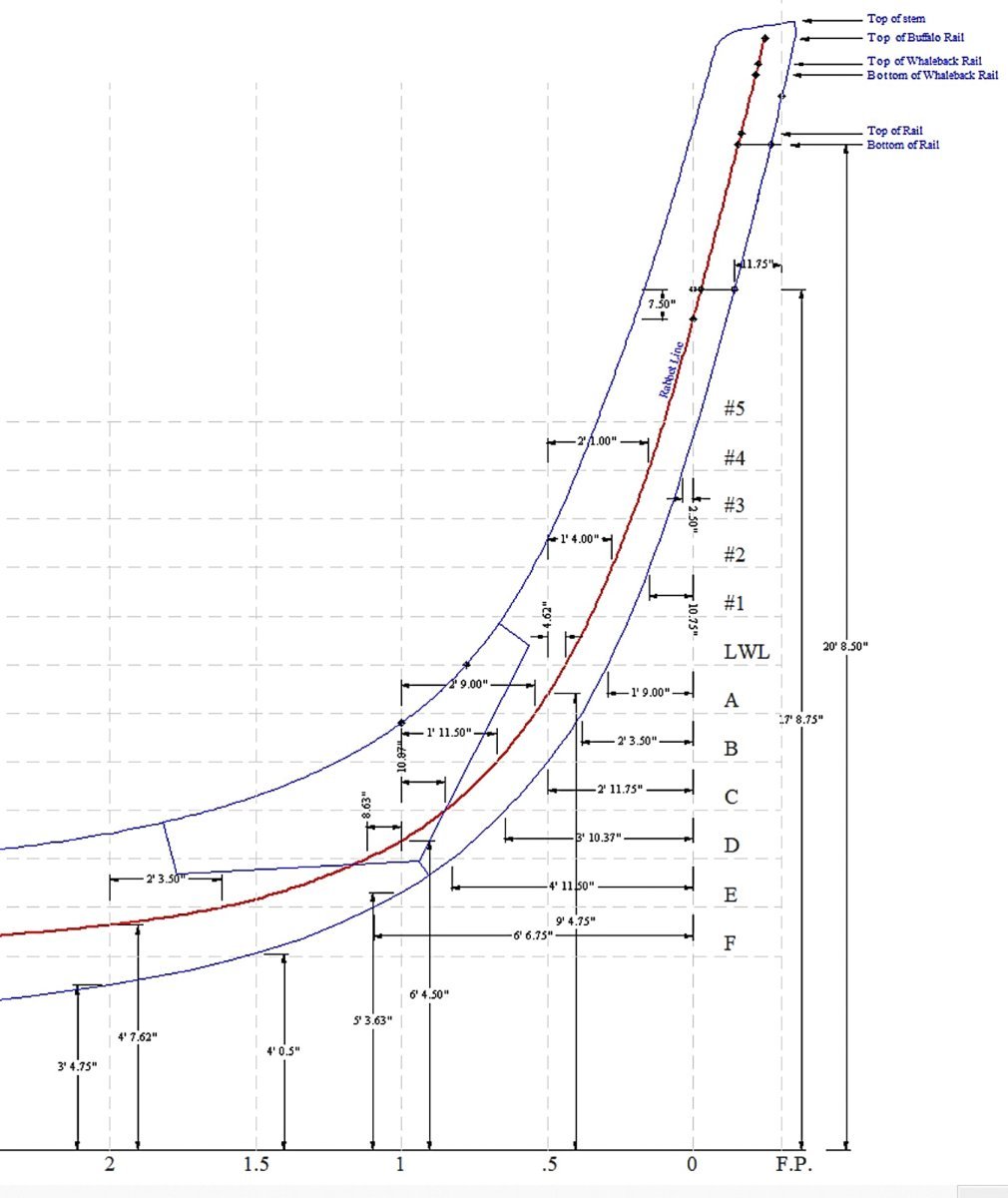
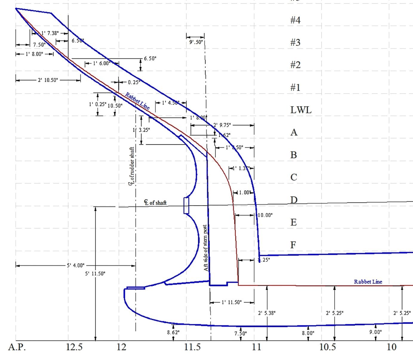
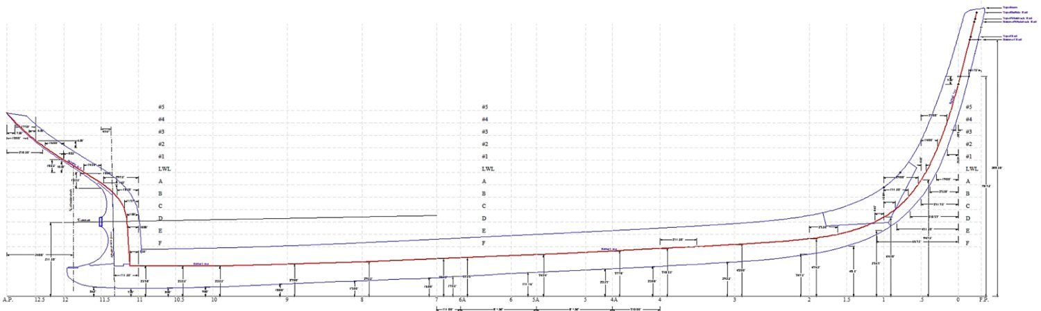
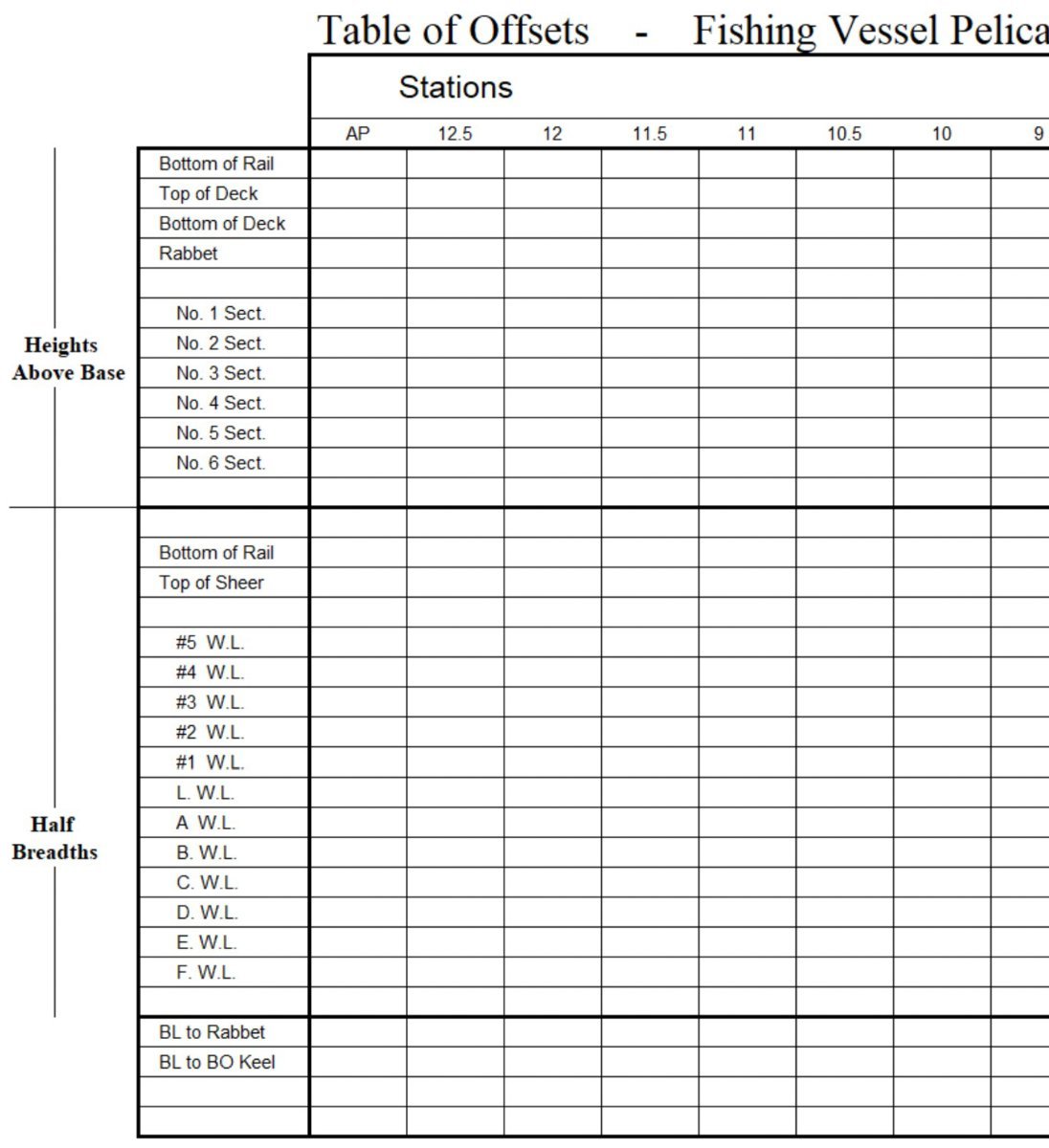
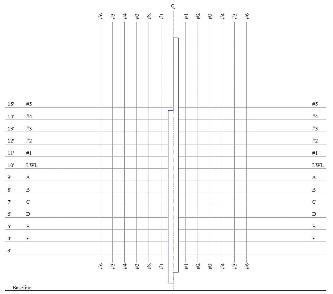
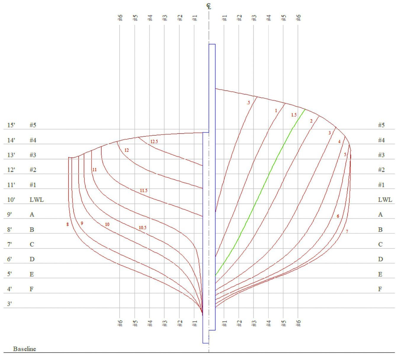
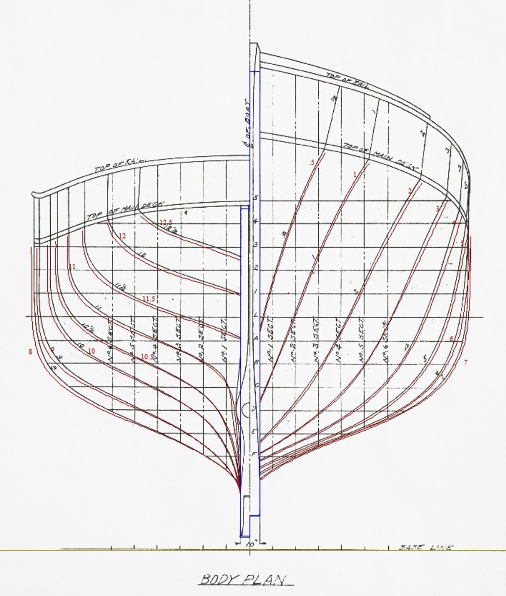
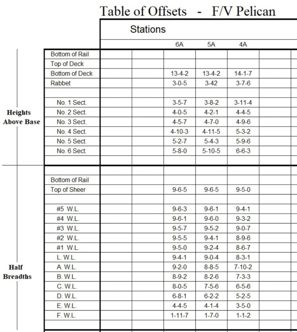
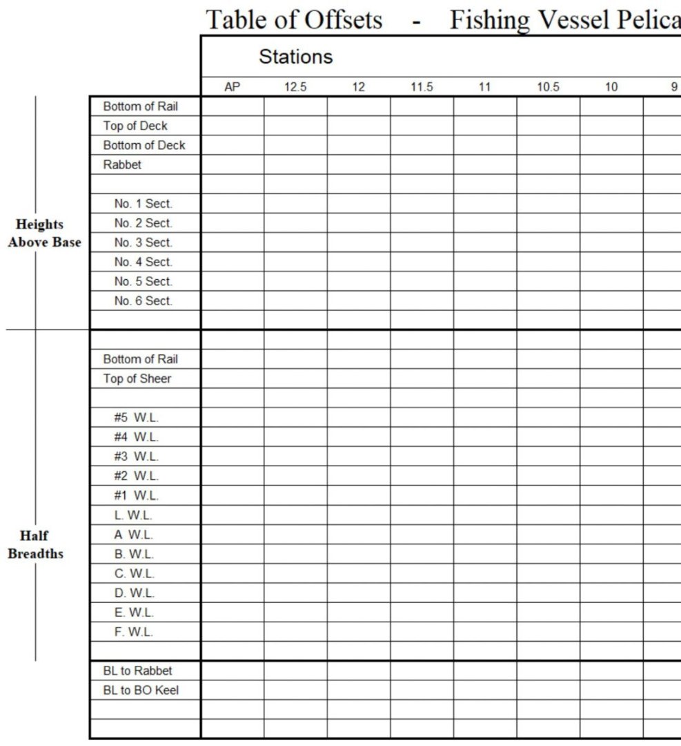
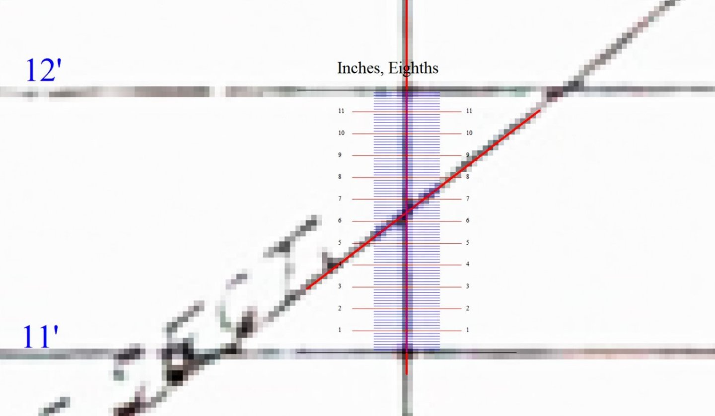
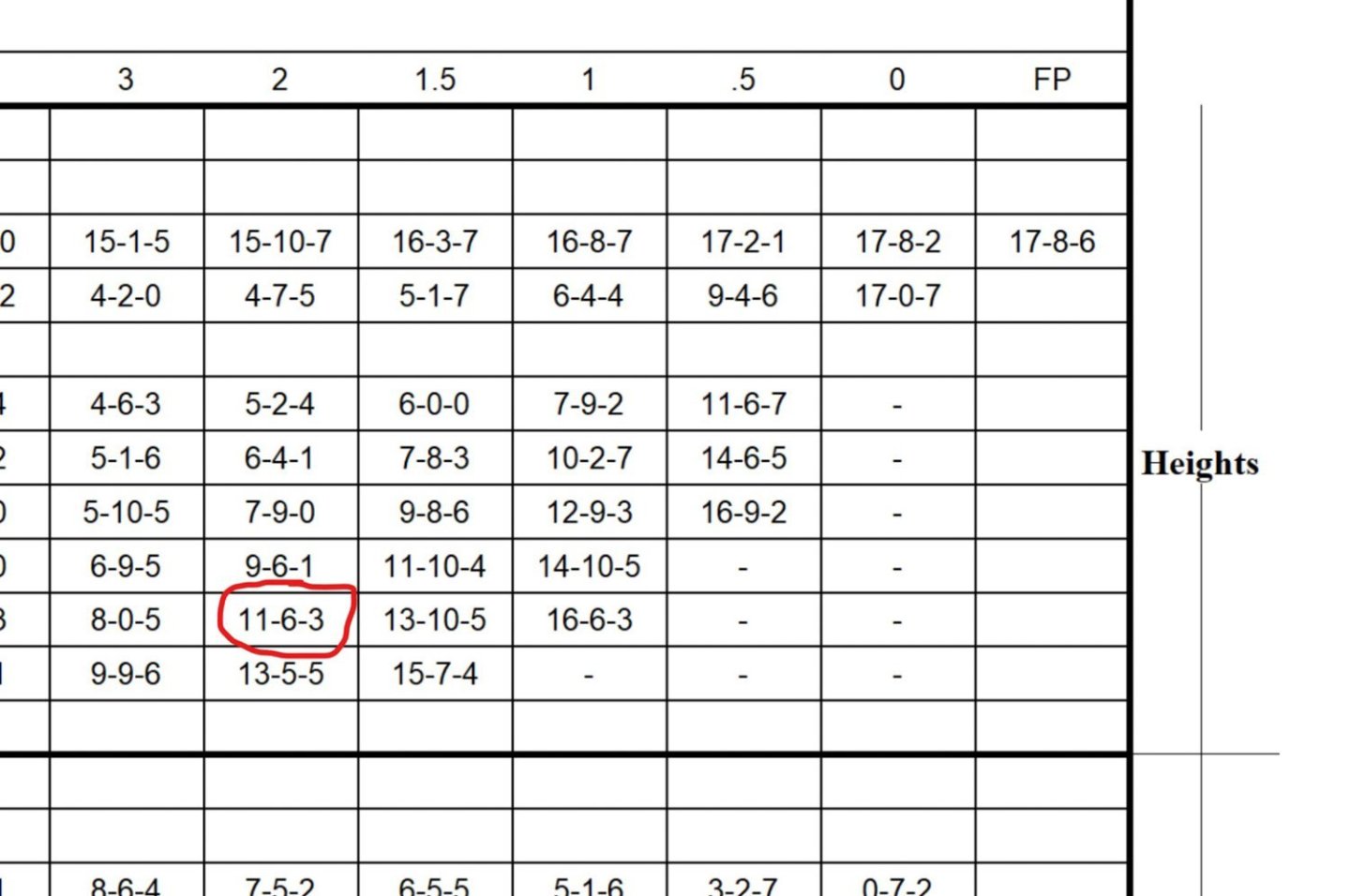
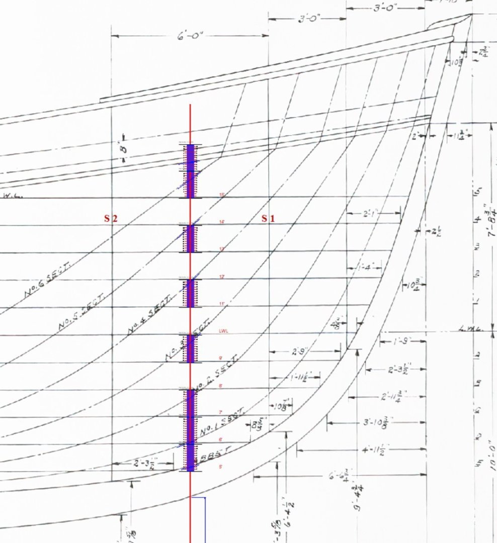
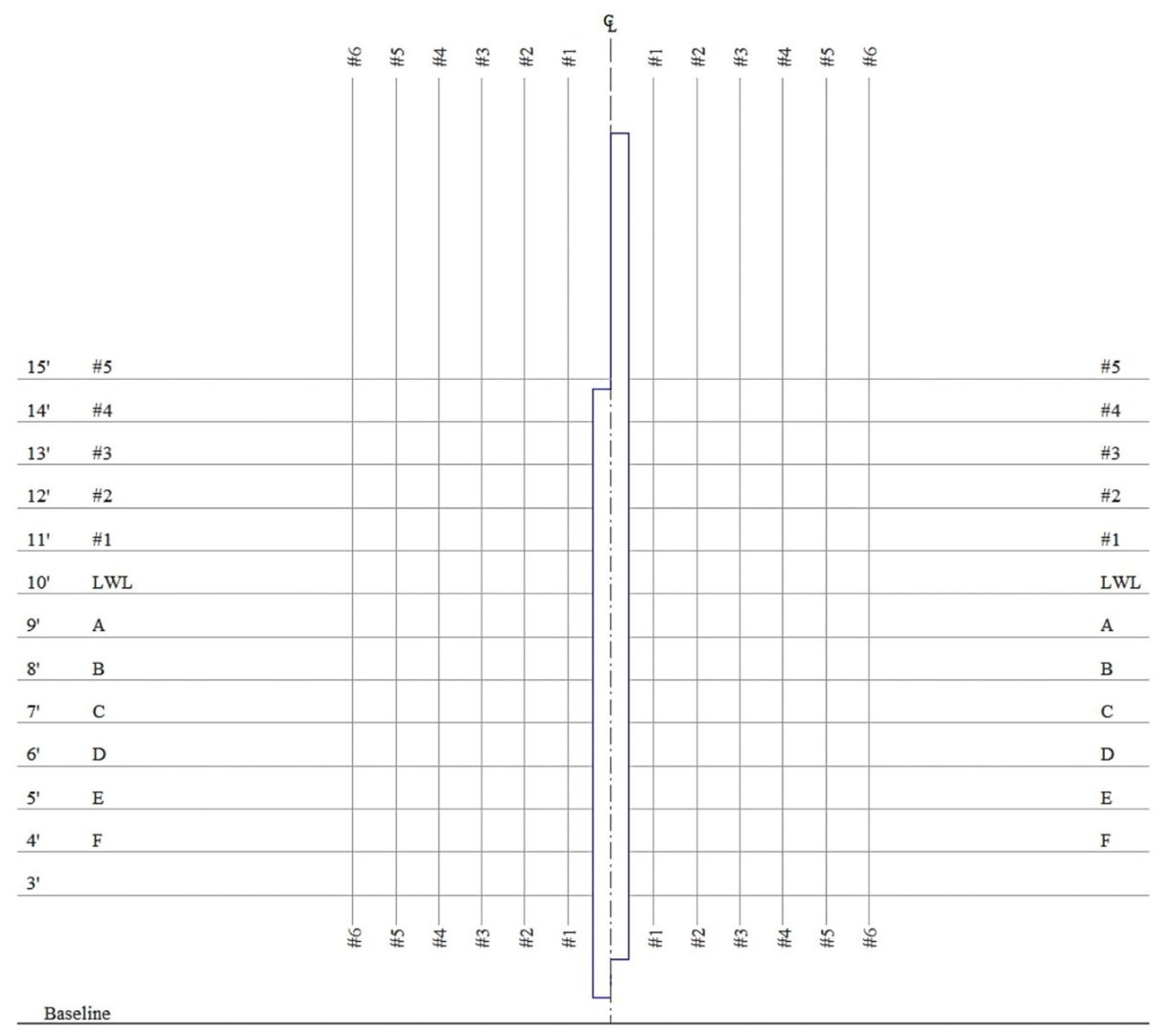
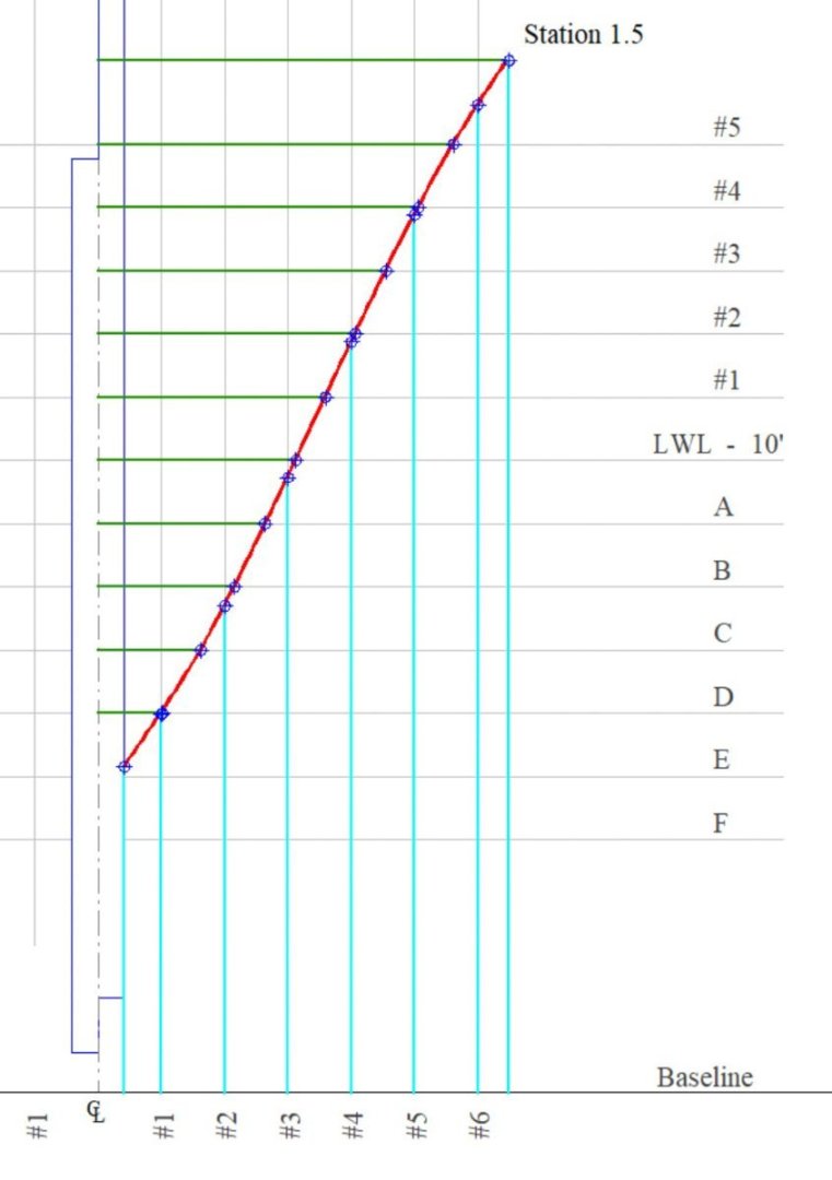
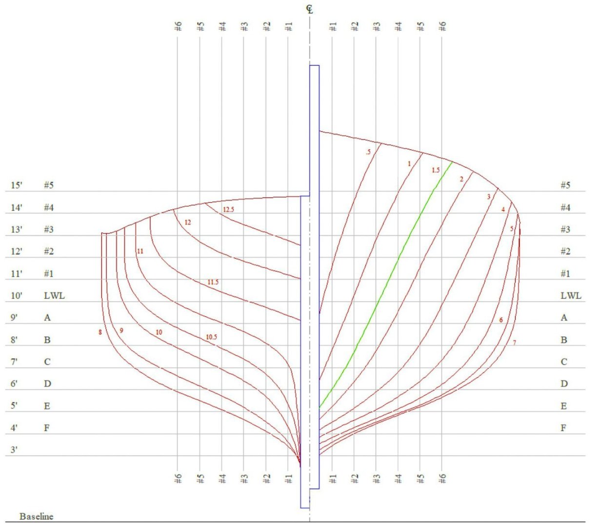
Greetings all, Druxey and Alexander - thanks for your interest in this build and for the nice words! It's so appreciated, and thanks to all for the likes. Plans for this boat came from the Mystic Seaport Research Center. They contain the outboard and inboard profiles, transverse sections, deck and arrangement below, deck framing and the lines. Unfortunately, there is no table of offsets for this boat and even though the catalog lists it - none could be found. And speaking of the boat plans catalog, it is available to view on the Mystic Seaport website, but it isn't downloadable. Here is the link to a digital pdf version that is. Boat Plans at Mystic Seaport - Digital Edition from OffCenterHarbor.com My copies of the plans are quite nice, but as I began working with them, I found the imprints are a little out of square. It's as if the paper sheets had slipped slightly through the copier rolls, not to great extent, but enough to throw what should be straight lines out of whack. Placing a 4' straight edge along a baseline shows the line hooking up or down - a mild curve rather than a straight line, and perpendicular lines veer out of square a short distance from their intersections. Because I imported these plans into CAD for dimensioning and scale printing, the photo process compounded the problem. After much spot checking and obsessing over the accuracy of the skewed lines, I decided to forgo tracing the keel and body plan and instead opted to generate replacements from scratch. This is something of a fool's errand because the differences wouldn't be evident in the final result, even if I were capable of modeling to that degree of precision, which I'm not. But I don't want to begin a new project with inaccuracies already built in. I prefer to create my own inaccuracies and errors, and pepper them throughout the build as I go. I began the process by entering points of intersection on the “half breadths” and “sheer” plans into a “table of offsets” from which to create a new body plan. This was a little time consuming but a straightforward process. First, I created a blank table in a spreadsheet to record all the heights and widths for every hull station. A partial view of that table is shown below. The sheet containing the “lines” is roughly 52” wide by 22” in height, and the greater the distance between any two points on the drawing the more unreliable the measure. So, when I measured the heights of section line crossings at individual stations, I took those measurements from the closest reference rather than the baseline. For the heights, that reference is the waterlines. To assist in that process, I created a macro in CAD that places a measuring ruler between two points of my choosing. It defaults to precisely one foot in length if I set only one insertion point, but it will stretch or shorten to redefine what constitutes 1' when I insert two points. I know the distance between waterlines is one foot, so I set the ruler to span the gap between waterlines at every station where a section line intersects it. In some locations, the default 1' ruler spanned the distance between waterlines precisely, while in other locations it fell short, and I ended up having to define those distances to be 1' by setting the second point. In the example above, the vertical line is station #2 where the #5 section line (buttock) crosses it between WL #1 and #2. In the U.S., offset data points are typically stated in feet-inches-eighths, so this height is 11-6-3 and I entered it into the offset table. I repeated this at every location where a section line crosses over a station line. Then I did the same for the half breadths on every station line where there is a waterline crossing. I also recorded rabbet heights, “bottom of deck at side” and “top of sheer” for every station. I decided to add an extra station between #1 and #2 because I'm concerned about a possible flat spot at that area. So, I struck a vertical line equidistant between stations 1 and 2 and recorded those heights also. I did the same for the half breadths. I created a body plan grid with a center line, horizontal water lines and vertical section lines. Then on to the process of plotting the offset points and connecting the dots with a curve. Below is the added station between #1 and #2 which I cleverly named #1.5. The green lines show half breadth distances, and the turquoise lines are the heights. Then I did the same for all the rest. I did have to nudge quite a few of the points around to obtain fair lines, but not nearly as many as I had anticipated. These nudges in most cases represented 1/4” corrections or less (on the full-size boat}, although I did have a point that was off by more than an inch. And I sloppily made several recording errors, transposed numbers and so on, but those were easy to find. Here's the station curves layered over the original plan sheet. This was before I added the station at 1.5. The match-up is actually closer than it appears because the original is warped in a way that explains some of the differences, but not all of them. Still, after checking and re-checking, I feel confident it will look like a boat in the end. This was an interesting and oddly enjoyable exercise although it didn't practically need to be done. But I'm glad I worked through it just the same. Next comes the backbone. Thanks for looking. Be safe and stay well. Gary
-
Missed this build log somehow but caught up now. Nice looking riverboat. Best of luck on this build and in the construction of your new shop. Hope you and the misses are back to normal. Gary
-
Nice looking little fishing boat, Maurino and she's coming along nicely. I like the ageing effects on the lamp also. Gary
-
Although I had heard of the RCMP schooner St. Roch, I knew very little about her. After searching her out on the web, I find she has a very interesting history indeed and is a good choice for a scale model. You're doing some very nice work on her so far and I look forward to future updates. Gary