

tlevine
-
Posts
1,966 -
Joined
-
Last visited
Reputation Activity
-

 tlevine reacted to dvm27 in Frayed lines
I'm afraid you're in a world of hurt Dindsy. I would treat one of the lift lines with a 50% white glue/water solution and see what it looks like after it dries. But I'm not optimistic. Being a cross-section, re-rigging it should not take much time at all and I would use the opportunity to upgrade the blocks and rigging line to Syren Models products. Your second effort will look far better and you'll be much happier in the long term.
Now, take a scissors and cut the main shrouds across the middle and you're committed to ship modelling excellence!
-
tlevine reacted to Stuntflyer in Sloop Speedwell 1752 by Stuntflyer (Mike) - Ketch Rigged Sloop - POF
Hull Planking, cont. .
It seems like forever since my last post. I had some personal matters to attend to amongst a few other things. Anyway, I'm looking forward to getting things back up to speed.
I'm working on a tricky part of the hull planking, those cutouts around the gun ports and sweep port lids. I really had to take my time here in order to avoid re-dos. The reveal around the gun ports is somewhere between 1/64"-1/32". A pillar file comes in really handy. It only cuts on one edge thus allowing for clean corner cuts. https://contenti.com/grobet-extra-narrow-pillar-files I use either a "0" and "2" cut.
I haven't done any sanding on the planking and as you can see it's a bit of a mess. The red color is Winsor & Newton "Crimson". In the past I would add a bit of Burnt Umber in order to darken the color. The two colors would often separate which I found to be a pain, so I decided to keep it simple this time around.
Mike
-
tlevine reacted to giampieroricci in HMS PEGASUS by giampieroricci - Scale 1:36 - Swan-Class Sloop from plans by David Antscherl & Greg Herbert
The belfry: technical implementation tests:
Final version in ebony wood:
-
tlevine reacted to Chuck in Sloop Speedwell 1752 by Chuck - Ketch Rigged Sloop - POF - prototype build
Thank you guys...we leave tomorrow.
Yes I am headed out to the north and south fork of Long Island. Gonna check out some maritime stuff including some museums that have small boat collections. Still researching that block island Cowhorn. There is supposed to be a nice one in the museum there. I will be online using my phone though....me always needs some MSW time....lol.
Planking has started...today.
The facstle is completed. Nothing to really add except that I followed the planking scheme provided on the plans. You can see that here. You guys may of course change it. I cut these from a 3/64" sheet following the plans rather than use strips. There is quite a pronounced curve to these and they are small enough so it wasnt a chore. I basically traced the plan sheet. Tweaked and sanded to suit. I used a #4H pencil to simulate the caulking between the planks.
Progress below. One plank at a time. The outermost planks are the hardest but not terrible.
-
.jpg.d84ec4dad1d7791e855dca06210ab6f3.thumb.jpg.f45209242e851d4409eca1a09293165b.jpg) tlevine got a reaction from hollowneck in NRG Rigging Project by tlevine - FINISHED
tlevine got a reaction from hollowneck in NRG Rigging Project by tlevine - FINISHED
I made the top by laminating two layers of 1/32” basswood sheeting, each at 90 degrees to each other. The kit will have a plywood template to trace the shape onto the basswood. This gave the correct thickness and added strength. On a real ship, the top was made up from tongue and grooved wood slats. I drew the edges of the slats onto the top with a #11 blade.
The top’s rim was made next. I used template to trace the curved section onto sheet basswood. The rim overlaps the edge of the top so draw another line onto the basswood 3.5” outwards from the first line. I made a second template by outlining the top and drew another line 3.5” inwards from the edge of the template on the curved edge and both sides. The template was trimmed at the inner line (see arrow below) and positioned on the basswood sheet 7” inwards from the first line. This gave me the shape of the curved part of the rim.
The rim was glued onto the top and weighted down until dry.
The front edge of the rim is raised. I used a 3 mm chisel to remove one-third of the thickness of the rim. If you do not have a chisel, you could use a sanding stick to shape the rim. The inner edge of the rim was feathered so that only one-third the thickness was left where it met the top.
The side pieces also they extend 3.5” beyond the edge of the top and their thickness tapers to one third the thickness on its inside edge. Because this piece is straight and with the grain, the tapering was done before it was glued to the top. When you turn the top upside down, you can see the overhanging edges fore and both sides.
The top has multiple slats extending from the edge to the center opening. The number depends on the size of the top. I have penciled in the locations of the slats for this top (see two pictures down). The slats that abut the curved portion of the rim have an unusual shape. They are cut away to allow them to rest on top of the rim and tapered to a point as they approach the center opening. Since they are all slightly different in shape, they were made individually. The slat does not extend over the raised edge. In the next picture I have incorrectly cut the side edges with a 45 degree bevel. It should be a straight cut.
The side slats pass through openings cut into the rim, and taper towards the center opening. I laminated six pieces of wood together and shaped them into a triangle. The height of the slat is flush with the rim. The slats were unglued, openings were cut into the rim and they were installed.
The aft slats are also triangular and extend to the edge of the top. Lastly, a gunwale was glued on top of the aft slats and the side rim. Take a look at this much later picture to see the relationships between the gunwale, side rim and aft slats.
-
 tlevine got a reaction from thibaultron in NRG Rigging Project by tlevine - FINISHED
I use a straight needle with a blunt tip. This is the kind typically used in counted cross-stitch.
-
 tlevine got a reaction from thibaultron in NRG Rigging Project by tlevine - FINISHED
The futtock staves were made from 3” served rope and are located as far below the trestle trees as the top of the mast is above the trestle trees, approximately seven feet. For ease of installation, I used served 24 gauge wire, rather than rope. They were lashed to the shrouds. The picture on the left shows the lashing in white for clarity and the finished product on the right.
And now it is time for the dreaded ratlines. There are some lines on a ship that are a do not change with the size of the ship, such as the footropes and ratlines, both of which must hold a seaman’s weight. The ratlines are made of tarred 1.5” rope. At this scale, I simply tied, rather than lashed, them to the outer shrouds. They are secured to the inner shrouds with clove hitch knots, a drawing of which is below. This picture is also from The Boy’s Manual.
Ratlines are spaced 12-15” apart and are parallel to the waterline. The easiest way to keep them even is to make a line jig. There is a tendency to pull the shrouds inward as the ratlines are added. I like to secure a brass rod or stick to the outer shrouds to keep them straight. This is my setup. The clips are holding the line jig in place. The ratlines are parallel to the waterline, not to the deck. After several hours, 220 knots and fifteen scale feet of rope, the ratlines were finished.
Catharpins are ropes with an eye at each end which extend across and are seized to the shrouds at the level of the futtock staves. According to Steel, sloops were not equipped with catharpins but I included them in the kit to illustrate their construction. I made them from 22 gauge wire with a loop on each end. As there is no tension on them, I did not solder the loops closed. The catharpins are served and the ends are painted black to simulate the eye splice. The first catharpin is located just aft of the mast and the other two are spaced out evenly along the futtock stave.
This completed the standing rigging of the lower mast. As mentioned earlier, because this is a cross section model, lines that would not terminate on the model, such as the stays and backstays, were omitted.
-
tlevine got a reaction from thibaultron in NRG Rigging Project by tlevine - FINISHED
The shrouds were installed next. The starboard shroud is always placed first and are they are installed from fore to aft. Because this ship has an odd number of shrouds, the first shroud is single; the rest are double. The first shroud is served its entire length, protecting it from the lower sail. The starboard and port first shrouds are secured to each other with a cut splice, just as was done with the pendant tackle.
The remaining paired shrouds are served where they could be chafed: the center 20-25%, based on the ship being rigged. I cut a two foot piece of line and marked the midpoint and 10% the length of the shroud on either side of the midpoint, in this case 1.2”. This is the area that was served. The doubled shrouds were secured with a throat seizing tight to the mast head. The lower ends of the served portion of the shrouds should be level when they are installed. This means that the throat seizing is not exactly in the middle of the served section, but offset enough to allow this to occur. You can see this in the next picture. The aft shroud seizing is slightly longer than the fore.
The shrouds were installed, alternating starboard and port, taking care to stack them neatly. The topmast is temporarily installed in the following pictures.
The next step was to attach the upper deadeyes to the shrouds. The distance between the upper and lower deadeyes is a constant. The easiest way to ensure this is to make a spacer jig. You will actually need ten, five for each side. The picture shows two jigs. The one on the left is made by soldering the two wires together. The other one uses twisted wire. The prongs go through the two inner deadeye holes.
I started by inserting the prongs through the upper holes of the lower deadeye and bent the wire around the back of the deadeye to prevent it from coming out. Next, I wrapped the shroud around the upper deadeye and adjusted the shroud length so that the upper deadeye could be threaded onto the jig. These shrouds are cable laid (left twist), so the short end of the shroud went on the aft side of the shroud. If the shrouds were rope (right twist), the short end would be on the fore side. I secured the shrouds to the deadeyes with alligator clips. I find it important to leave the model alone for several hours at this point. This allows the rope to stretch and helps prevent sagging in the future.
The upper deadeyes are secured with three seizings. A cross seizing was placed where the shroud crossed over itself next to the deadeye. I marked the location of the cross seizing on both sides of the shroud and removed the deadeye. If left in, the loop is too big. After making the cross seizing, the deadeye was reinserted and the middle and end round seizings were added. The drawing shows a round seizing.
And the picture illustrates the relative location of the seizings, using white thread to make it easier for you to see.
Brown paint was used to represent the leather cap at the end of the shroud.
The shroud lanyards were installed next. They are considered running rigging and are not tarred. A knot was tied at the end of the lanyard and it was inserted through the back of the upper deadeye in the foremost hole. After reeving it through the deadeye, excess line was kept for tying off. Once they were done, the lanyards were gradually tightened, making sure the mast was straight. Just like with the shrouds, I gave it a few hours to allow the line to stretch. To tie off the lanyard, the rope was passed between the shroud and the deadeye (below left) and looped under the last line of the lanyard (below right). The lanyard was wrapped around the shroud a few times and finished by inserting it under the last loop.
-
tlevine reacted to Chuck in Sloop Speedwell 1752 by Chuck - Ketch Rigged Sloop - POF - prototype build
Just a quick follow up....All of the coamings and hatches and partners are now glued onto the model. Not much to see but here are the details.
The mast partners went in first. Really important was to get them down the center line so your masts arent slanted or crooked. It is best to use a dowel or even any strip of wood near the same diameter as the masts to also check the rake of the masts to determine the position of the partners. I dont have a picture of that but you guys mostly know this already.
The main mast partners needed to have the pump tubes made before I could glue it on the model. I am only making the pump tubes below deck at this time much like Greg did on his model. I used a 1/4 x 1/4 cedar strip and marked it out to become octagonal. I used the 7-10-7 template provided on the plans. You can see it in the picture below. Then I drew lines down each side so I could begin shaving the corners. I just use a sharp #11 blade to carefully shave the corners down to the lines. Just before the lines actually. Then I use a sanding stick to finish it off. Some of you may have some machines that could do this more accurately but this works just fine.
You will notice a small length of 19 gauge black wire I inserted into the top end. This will be inserted into the holes laser cut in partners. The pump tubes are not vertical...so when glued into the bottom of the mast partner I created the slant for these using the plans as a guide.
Then it was just a matter of gluing the main mast partners onto the model. You can barely see these pump tubes under the partners but here is a bad photo showing them entering the well below deck. We will make the top half of the pumps much later and the same holes on the mast partners will be used to register them so they look continuous through the deck. So dont make the wire too long on the top of the tubes. Make them short enough so some room remains to do the same when we add the top of the elm tree pumps later.
The other gratings and hatches were added down the center line permanently.
The last remaining issue was the capstan partners. We need to make the capstan drum below deck. This is easy enough. Its just a round drum that tapers. I started with a 3/8 x 3/8 strip of cedar. Then I converted that into an octagon just like we did for the pump tubes. I have provided another 7-10-7 template for this strip so you can proceed to make it an octagon.
Here is a photo after I rounded it off and tapered the octagon. I just dis this by hand but you can chock it in a hand drill or if you happen to have a lathe....have at it. The length can be taken from the plans as well as the diameter at the bottom so it fits in the capstan step below deck.
Once completed I glued the capstan partner onto the center line of the deck so the drum sits in the step nicely. You might also notice that I made the drum a certain length so there was still room in the hole of the capstan partners. This will allow me to register the actual capstan above deck after we make it. Hope that makes sense.
Thats it for now as I am off to the beach for a few days to recharge....and decompress. I will be back sometime next week ......or maybe not....
-
tlevine reacted to Chuck in Sloop Speedwell 1752 by Chuck - Ketch Rigged Sloop - POF - prototype build
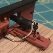
the rings are made in the usual manner. Wrapped around a 47 drill bit and parted with a razor saw. The bent wire is much lighter and thinner gauge. In my case here…24 gauge for the split rings and 28 gauge for the codder pin bent and inserted into the deck.
-
 tlevine got a reaction from CiscoH in NRG Rigging Project by tlevine - FINISHED
I made the top by laminating two layers of 1/32” basswood sheeting, each at 90 degrees to each other. The kit will have a plywood template to trace the shape onto the basswood. This gave the correct thickness and added strength. On a real ship, the top was made up from tongue and grooved wood slats. I drew the edges of the slats onto the top with a #11 blade.
The top’s rim was made next. I used template to trace the curved section onto sheet basswood. The rim overlaps the edge of the top so draw another line onto the basswood 3.5” outwards from the first line. I made a second template by outlining the top and drew another line 3.5” inwards from the edge of the template on the curved edge and both sides. The template was trimmed at the inner line (see arrow below) and positioned on the basswood sheet 7” inwards from the first line. This gave me the shape of the curved part of the rim.
The rim was glued onto the top and weighted down until dry.
The front edge of the rim is raised. I used a 3 mm chisel to remove one-third of the thickness of the rim. If you do not have a chisel, you could use a sanding stick to shape the rim. The inner edge of the rim was feathered so that only one-third the thickness was left where it met the top.
The side pieces also they extend 3.5” beyond the edge of the top and their thickness tapers to one third the thickness on its inside edge. Because this piece is straight and with the grain, the tapering was done before it was glued to the top. When you turn the top upside down, you can see the overhanging edges fore and both sides.
The top has multiple slats extending from the edge to the center opening. The number depends on the size of the top. I have penciled in the locations of the slats for this top (see two pictures down). The slats that abut the curved portion of the rim have an unusual shape. They are cut away to allow them to rest on top of the rim and tapered to a point as they approach the center opening. Since they are all slightly different in shape, they were made individually. The slat does not extend over the raised edge. In the next picture I have incorrectly cut the side edges with a 45 degree bevel. It should be a straight cut.
The side slats pass through openings cut into the rim, and taper towards the center opening. I laminated six pieces of wood together and shaped them into a triangle. The height of the slat is flush with the rim. The slats were unglued, openings were cut into the rim and they were installed.
The aft slats are also triangular and extend to the edge of the top. Lastly, a gunwale was glued on top of the aft slats and the side rim. Take a look at this much later picture to see the relationships between the gunwale, side rim and aft slats.
-
 tlevine got a reaction from Seventynet in NRG Rigging Project by tlevine - FINISHED
I made the top by laminating two layers of 1/32” basswood sheeting, each at 90 degrees to each other. The kit will have a plywood template to trace the shape onto the basswood. This gave the correct thickness and added strength. On a real ship, the top was made up from tongue and grooved wood slats. I drew the edges of the slats onto the top with a #11 blade.
The top’s rim was made next. I used template to trace the curved section onto sheet basswood. The rim overlaps the edge of the top so draw another line onto the basswood 3.5” outwards from the first line. I made a second template by outlining the top and drew another line 3.5” inwards from the edge of the template on the curved edge and both sides. The template was trimmed at the inner line (see arrow below) and positioned on the basswood sheet 7” inwards from the first line. This gave me the shape of the curved part of the rim.
The rim was glued onto the top and weighted down until dry.
The front edge of the rim is raised. I used a 3 mm chisel to remove one-third of the thickness of the rim. If you do not have a chisel, you could use a sanding stick to shape the rim. The inner edge of the rim was feathered so that only one-third the thickness was left where it met the top.
The side pieces also they extend 3.5” beyond the edge of the top and their thickness tapers to one third the thickness on its inside edge. Because this piece is straight and with the grain, the tapering was done before it was glued to the top. When you turn the top upside down, you can see the overhanging edges fore and both sides.
The top has multiple slats extending from the edge to the center opening. The number depends on the size of the top. I have penciled in the locations of the slats for this top (see two pictures down). The slats that abut the curved portion of the rim have an unusual shape. They are cut away to allow them to rest on top of the rim and tapered to a point as they approach the center opening. Since they are all slightly different in shape, they were made individually. The slat does not extend over the raised edge. In the next picture I have incorrectly cut the side edges with a 45 degree bevel. It should be a straight cut.
The side slats pass through openings cut into the rim, and taper towards the center opening. I laminated six pieces of wood together and shaped them into a triangle. The height of the slat is flush with the rim. The slats were unglued, openings were cut into the rim and they were installed.
The aft slats are also triangular and extend to the edge of the top. Lastly, a gunwale was glued on top of the aft slats and the side rim. Take a look at this much later picture to see the relationships between the gunwale, side rim and aft slats.
-
 tlevine got a reaction from druxey in NRG Rigging Project by tlevine - FINISHED
I made the top by laminating two layers of 1/32” basswood sheeting, each at 90 degrees to each other. The kit will have a plywood template to trace the shape onto the basswood. This gave the correct thickness and added strength. On a real ship, the top was made up from tongue and grooved wood slats. I drew the edges of the slats onto the top with a #11 blade.
The top’s rim was made next. I used template to trace the curved section onto sheet basswood. The rim overlaps the edge of the top so draw another line onto the basswood 3.5” outwards from the first line. I made a second template by outlining the top and drew another line 3.5” inwards from the edge of the template on the curved edge and both sides. The template was trimmed at the inner line (see arrow below) and positioned on the basswood sheet 7” inwards from the first line. This gave me the shape of the curved part of the rim.
The rim was glued onto the top and weighted down until dry.
The front edge of the rim is raised. I used a 3 mm chisel to remove one-third of the thickness of the rim. If you do not have a chisel, you could use a sanding stick to shape the rim. The inner edge of the rim was feathered so that only one-third the thickness was left where it met the top.
The side pieces also they extend 3.5” beyond the edge of the top and their thickness tapers to one third the thickness on its inside edge. Because this piece is straight and with the grain, the tapering was done before it was glued to the top. When you turn the top upside down, you can see the overhanging edges fore and both sides.
The top has multiple slats extending from the edge to the center opening. The number depends on the size of the top. I have penciled in the locations of the slats for this top (see two pictures down). The slats that abut the curved portion of the rim have an unusual shape. They are cut away to allow them to rest on top of the rim and tapered to a point as they approach the center opening. Since they are all slightly different in shape, they were made individually. The slat does not extend over the raised edge. In the next picture I have incorrectly cut the side edges with a 45 degree bevel. It should be a straight cut.
The side slats pass through openings cut into the rim, and taper towards the center opening. I laminated six pieces of wood together and shaped them into a triangle. The height of the slat is flush with the rim. The slats were unglued, openings were cut into the rim and they were installed.
The aft slats are also triangular and extend to the edge of the top. Lastly, a gunwale was glued on top of the aft slats and the side rim. Take a look at this much later picture to see the relationships between the gunwale, side rim and aft slats.
-
tlevine reacted to Chuck in Sloop Speedwell 1752 by Chuck - Ketch Rigged Sloop - POF - prototype build
Thank you Jim...
I have completed all of the hatches, gratings and partners to be placed on deck. You have seen how the gratings were made. The two hatches are pretty similar. The only difference is they have cover boards rather than gratings within in the coamings.
The photo below shows the laser cut coamings assembled. There is no need to remove the laser char from the lap joints at the corners. In fact it probably isnt a good idea at all. They are precision cut so you end up with a perfectly squared up coaming the correct size. You can and should sand both sides of the sheet before removing these laser cut parts to clean the char from those sides. Just glue them up using the same right angle jig provided earlier. Then sand the char off the top of the completed coaming being careful to keep the round-up consistent.
You can see the smaller hatch completed. The larger one shows the three cover boards also laser cut waiting to be glued into position. But this you will also note the ledge created on the inside of the coaming that the cover boards will sit into. These are laser cut for you and can be glued on the port and starboard insides of the coaming.
This photo shows the three coverboards in the coaming. They are pretty thick, but only so they are flush with the center of the coaming to allow for the round-up. The round-up along the sides of the coverboards should be sanded flush to the top edge of the coamings along the P & S sides. I know some folks like to show one or two coverboards off the coaming. You can do this if you want to. But then you should sand that roundup into the bottom of the coverboards as well. But I will show them all in place like the contemporary model.
To finish off the hatches...round off the corners using the right angle jig like you did for the gratings. Trim them down to the top of the deck planking. The bolts were added using black fishing line in the same way. The iron ring for handles were made just like those on the lower platforms. Exactly the same.
Also shown in the photo above are the mast and capstan partners. These are completely laser cut for you. They have etched lines to show the separate sections. All you have to do is sand them clean and round off the corners as described earlier for the capstan partners only. Soften the top edges as well. Add the fishing line bolts and the eye bolts on the main mast partners. Now some of these can be glued onto the model. They are all ready to go so you can start planking the decks.
BUT there are a some like the main mast partners and capstan partners that need some extra work. I will describe that next. For example the elm pump tubes below the main mast partners and the capstan drum as well.
More to follow...but here is a photo with the all of the hatches, coamings and partners simply test positioned on the model. They are not glued into position yet. I did however glue the smaller grating and coaming on the forecastle deck in permanently....those are all finished up. Its getting there!!!
-
tlevine reacted to mtaylor in 18th-Century Merchantman Half-Hull Planking Project by mtaylor - NRG
Another update. Slow going with RL getting in the way at the moment. Got the bulwark tops trimmed and am pretty happy. I know the photo appears to show all the tops trimmed below the line but that's the camera angle's fault. A square shows me it's spot on.
-
tlevine got a reaction from thibaultron in NRG Rigging Project by tlevine - FINISHED
I made the top by laminating two layers of 1/32” basswood sheeting, each at 90 degrees to each other. The kit will have a plywood template to trace the shape onto the basswood. This gave the correct thickness and added strength. On a real ship, the top was made up from tongue and grooved wood slats. I drew the edges of the slats onto the top with a #11 blade.
The top’s rim was made next. I used template to trace the curved section onto sheet basswood. The rim overlaps the edge of the top so draw another line onto the basswood 3.5” outwards from the first line. I made a second template by outlining the top and drew another line 3.5” inwards from the edge of the template on the curved edge and both sides. The template was trimmed at the inner line (see arrow below) and positioned on the basswood sheet 7” inwards from the first line. This gave me the shape of the curved part of the rim.
The rim was glued onto the top and weighted down until dry.
The front edge of the rim is raised. I used a 3 mm chisel to remove one-third of the thickness of the rim. If you do not have a chisel, you could use a sanding stick to shape the rim. The inner edge of the rim was feathered so that only one-third the thickness was left where it met the top.
The side pieces also they extend 3.5” beyond the edge of the top and their thickness tapers to one third the thickness on its inside edge. Because this piece is straight and with the grain, the tapering was done before it was glued to the top. When you turn the top upside down, you can see the overhanging edges fore and both sides.
The top has multiple slats extending from the edge to the center opening. The number depends on the size of the top. I have penciled in the locations of the slats for this top (see two pictures down). The slats that abut the curved portion of the rim have an unusual shape. They are cut away to allow them to rest on top of the rim and tapered to a point as they approach the center opening. Since they are all slightly different in shape, they were made individually. The slat does not extend over the raised edge. In the next picture I have incorrectly cut the side edges with a 45 degree bevel. It should be a straight cut.
The side slats pass through openings cut into the rim, and taper towards the center opening. I laminated six pieces of wood together and shaped them into a triangle. The height of the slat is flush with the rim. The slats were unglued, openings were cut into the rim and they were installed.
The aft slats are also triangular and extend to the edge of the top. Lastly, a gunwale was glued on top of the aft slats and the side rim. Take a look at this much later picture to see the relationships between the gunwale, side rim and aft slats.
-
 tlevine got a reaction from KentM in NRG Rigging Project by tlevine - FINISHED
I made the top by laminating two layers of 1/32” basswood sheeting, each at 90 degrees to each other. The kit will have a plywood template to trace the shape onto the basswood. This gave the correct thickness and added strength. On a real ship, the top was made up from tongue and grooved wood slats. I drew the edges of the slats onto the top with a #11 blade.
The top’s rim was made next. I used template to trace the curved section onto sheet basswood. The rim overlaps the edge of the top so draw another line onto the basswood 3.5” outwards from the first line. I made a second template by outlining the top and drew another line 3.5” inwards from the edge of the template on the curved edge and both sides. The template was trimmed at the inner line (see arrow below) and positioned on the basswood sheet 7” inwards from the first line. This gave me the shape of the curved part of the rim.
The rim was glued onto the top and weighted down until dry.
The front edge of the rim is raised. I used a 3 mm chisel to remove one-third of the thickness of the rim. If you do not have a chisel, you could use a sanding stick to shape the rim. The inner edge of the rim was feathered so that only one-third the thickness was left where it met the top.
The side pieces also they extend 3.5” beyond the edge of the top and their thickness tapers to one third the thickness on its inside edge. Because this piece is straight and with the grain, the tapering was done before it was glued to the top. When you turn the top upside down, you can see the overhanging edges fore and both sides.
The top has multiple slats extending from the edge to the center opening. The number depends on the size of the top. I have penciled in the locations of the slats for this top (see two pictures down). The slats that abut the curved portion of the rim have an unusual shape. They are cut away to allow them to rest on top of the rim and tapered to a point as they approach the center opening. Since they are all slightly different in shape, they were made individually. The slat does not extend over the raised edge. In the next picture I have incorrectly cut the side edges with a 45 degree bevel. It should be a straight cut.
The side slats pass through openings cut into the rim, and taper towards the center opening. I laminated six pieces of wood together and shaped them into a triangle. The height of the slat is flush with the rim. The slats were unglued, openings were cut into the rim and they were installed.
The aft slats are also triangular and extend to the edge of the top. Lastly, a gunwale was glued on top of the aft slats and the side rim. Take a look at this much later picture to see the relationships between the gunwale, side rim and aft slats.
-
 tlevine got a reaction from _SalD_ in NRG Rigging Project by tlevine - FINISHED
I made the top by laminating two layers of 1/32” basswood sheeting, each at 90 degrees to each other. The kit will have a plywood template to trace the shape onto the basswood. This gave the correct thickness and added strength. On a real ship, the top was made up from tongue and grooved wood slats. I drew the edges of the slats onto the top with a #11 blade.
The top’s rim was made next. I used template to trace the curved section onto sheet basswood. The rim overlaps the edge of the top so draw another line onto the basswood 3.5” outwards from the first line. I made a second template by outlining the top and drew another line 3.5” inwards from the edge of the template on the curved edge and both sides. The template was trimmed at the inner line (see arrow below) and positioned on the basswood sheet 7” inwards from the first line. This gave me the shape of the curved part of the rim.
The rim was glued onto the top and weighted down until dry.
The front edge of the rim is raised. I used a 3 mm chisel to remove one-third of the thickness of the rim. If you do not have a chisel, you could use a sanding stick to shape the rim. The inner edge of the rim was feathered so that only one-third the thickness was left where it met the top.
The side pieces also they extend 3.5” beyond the edge of the top and their thickness tapers to one third the thickness on its inside edge. Because this piece is straight and with the grain, the tapering was done before it was glued to the top. When you turn the top upside down, you can see the overhanging edges fore and both sides.
The top has multiple slats extending from the edge to the center opening. The number depends on the size of the top. I have penciled in the locations of the slats for this top (see two pictures down). The slats that abut the curved portion of the rim have an unusual shape. They are cut away to allow them to rest on top of the rim and tapered to a point as they approach the center opening. Since they are all slightly different in shape, they were made individually. The slat does not extend over the raised edge. In the next picture I have incorrectly cut the side edges with a 45 degree bevel. It should be a straight cut.
The side slats pass through openings cut into the rim, and taper towards the center opening. I laminated six pieces of wood together and shaped them into a triangle. The height of the slat is flush with the rim. The slats were unglued, openings were cut into the rim and they were installed.
The aft slats are also triangular and extend to the edge of the top. Lastly, a gunwale was glued on top of the aft slats and the side rim. Take a look at this much later picture to see the relationships between the gunwale, side rim and aft slats.
-
 tlevine got a reaction from theoracle09 in NRG Rigging Project by tlevine - FINISHED
I made the top by laminating two layers of 1/32” basswood sheeting, each at 90 degrees to each other. The kit will have a plywood template to trace the shape onto the basswood. This gave the correct thickness and added strength. On a real ship, the top was made up from tongue and grooved wood slats. I drew the edges of the slats onto the top with a #11 blade.
The top’s rim was made next. I used template to trace the curved section onto sheet basswood. The rim overlaps the edge of the top so draw another line onto the basswood 3.5” outwards from the first line. I made a second template by outlining the top and drew another line 3.5” inwards from the edge of the template on the curved edge and both sides. The template was trimmed at the inner line (see arrow below) and positioned on the basswood sheet 7” inwards from the first line. This gave me the shape of the curved part of the rim.
The rim was glued onto the top and weighted down until dry.
The front edge of the rim is raised. I used a 3 mm chisel to remove one-third of the thickness of the rim. If you do not have a chisel, you could use a sanding stick to shape the rim. The inner edge of the rim was feathered so that only one-third the thickness was left where it met the top.
The side pieces also they extend 3.5” beyond the edge of the top and their thickness tapers to one third the thickness on its inside edge. Because this piece is straight and with the grain, the tapering was done before it was glued to the top. When you turn the top upside down, you can see the overhanging edges fore and both sides.
The top has multiple slats extending from the edge to the center opening. The number depends on the size of the top. I have penciled in the locations of the slats for this top (see two pictures down). The slats that abut the curved portion of the rim have an unusual shape. They are cut away to allow them to rest on top of the rim and tapered to a point as they approach the center opening. Since they are all slightly different in shape, they were made individually. The slat does not extend over the raised edge. In the next picture I have incorrectly cut the side edges with a 45 degree bevel. It should be a straight cut.
The side slats pass through openings cut into the rim, and taper towards the center opening. I laminated six pieces of wood together and shaped them into a triangle. The height of the slat is flush with the rim. The slats were unglued, openings were cut into the rim and they were installed.
The aft slats are also triangular and extend to the edge of the top. Lastly, a gunwale was glued on top of the aft slats and the side rim. Take a look at this much later picture to see the relationships between the gunwale, side rim and aft slats.
-
 tlevine got a reaction from Canute in NRG Rigging Project by tlevine - FINISHED
I made the top by laminating two layers of 1/32” basswood sheeting, each at 90 degrees to each other. The kit will have a plywood template to trace the shape onto the basswood. This gave the correct thickness and added strength. On a real ship, the top was made up from tongue and grooved wood slats. I drew the edges of the slats onto the top with a #11 blade.
The top’s rim was made next. I used template to trace the curved section onto sheet basswood. The rim overlaps the edge of the top so draw another line onto the basswood 3.5” outwards from the first line. I made a second template by outlining the top and drew another line 3.5” inwards from the edge of the template on the curved edge and both sides. The template was trimmed at the inner line (see arrow below) and positioned on the basswood sheet 7” inwards from the first line. This gave me the shape of the curved part of the rim.
The rim was glued onto the top and weighted down until dry.
The front edge of the rim is raised. I used a 3 mm chisel to remove one-third of the thickness of the rim. If you do not have a chisel, you could use a sanding stick to shape the rim. The inner edge of the rim was feathered so that only one-third the thickness was left where it met the top.
The side pieces also they extend 3.5” beyond the edge of the top and their thickness tapers to one third the thickness on its inside edge. Because this piece is straight and with the grain, the tapering was done before it was glued to the top. When you turn the top upside down, you can see the overhanging edges fore and both sides.
The top has multiple slats extending from the edge to the center opening. The number depends on the size of the top. I have penciled in the locations of the slats for this top (see two pictures down). The slats that abut the curved portion of the rim have an unusual shape. They are cut away to allow them to rest on top of the rim and tapered to a point as they approach the center opening. Since they are all slightly different in shape, they were made individually. The slat does not extend over the raised edge. In the next picture I have incorrectly cut the side edges with a 45 degree bevel. It should be a straight cut.
The side slats pass through openings cut into the rim, and taper towards the center opening. I laminated six pieces of wood together and shaped them into a triangle. The height of the slat is flush with the rim. The slats were unglued, openings were cut into the rim and they were installed.
The aft slats are also triangular and extend to the edge of the top. Lastly, a gunwale was glued on top of the aft slats and the side rim. Take a look at this much later picture to see the relationships between the gunwale, side rim and aft slats.
-
 tlevine got a reaction from rcweir in NRG Rigging Project by tlevine - FINISHED
I made the top by laminating two layers of 1/32” basswood sheeting, each at 90 degrees to each other. The kit will have a plywood template to trace the shape onto the basswood. This gave the correct thickness and added strength. On a real ship, the top was made up from tongue and grooved wood slats. I drew the edges of the slats onto the top with a #11 blade.
The top’s rim was made next. I used template to trace the curved section onto sheet basswood. The rim overlaps the edge of the top so draw another line onto the basswood 3.5” outwards from the first line. I made a second template by outlining the top and drew another line 3.5” inwards from the edge of the template on the curved edge and both sides. The template was trimmed at the inner line (see arrow below) and positioned on the basswood sheet 7” inwards from the first line. This gave me the shape of the curved part of the rim.
The rim was glued onto the top and weighted down until dry.
The front edge of the rim is raised. I used a 3 mm chisel to remove one-third of the thickness of the rim. If you do not have a chisel, you could use a sanding stick to shape the rim. The inner edge of the rim was feathered so that only one-third the thickness was left where it met the top.
The side pieces also they extend 3.5” beyond the edge of the top and their thickness tapers to one third the thickness on its inside edge. Because this piece is straight and with the grain, the tapering was done before it was glued to the top. When you turn the top upside down, you can see the overhanging edges fore and both sides.
The top has multiple slats extending from the edge to the center opening. The number depends on the size of the top. I have penciled in the locations of the slats for this top (see two pictures down). The slats that abut the curved portion of the rim have an unusual shape. They are cut away to allow them to rest on top of the rim and tapered to a point as they approach the center opening. Since they are all slightly different in shape, they were made individually. The slat does not extend over the raised edge. In the next picture I have incorrectly cut the side edges with a 45 degree bevel. It should be a straight cut.
The side slats pass through openings cut into the rim, and taper towards the center opening. I laminated six pieces of wood together and shaped them into a triangle. The height of the slat is flush with the rim. The slats were unglued, openings were cut into the rim and they were installed.
The aft slats are also triangular and extend to the edge of the top. Lastly, a gunwale was glued on top of the aft slats and the side rim. Take a look at this much later picture to see the relationships between the gunwale, side rim and aft slats.
-
 tlevine got a reaction from robert952 in NRG Rigging Project by tlevine - FINISHED
I made the top by laminating two layers of 1/32” basswood sheeting, each at 90 degrees to each other. The kit will have a plywood template to trace the shape onto the basswood. This gave the correct thickness and added strength. On a real ship, the top was made up from tongue and grooved wood slats. I drew the edges of the slats onto the top with a #11 blade.
The top’s rim was made next. I used template to trace the curved section onto sheet basswood. The rim overlaps the edge of the top so draw another line onto the basswood 3.5” outwards from the first line. I made a second template by outlining the top and drew another line 3.5” inwards from the edge of the template on the curved edge and both sides. The template was trimmed at the inner line (see arrow below) and positioned on the basswood sheet 7” inwards from the first line. This gave me the shape of the curved part of the rim.
The rim was glued onto the top and weighted down until dry.
The front edge of the rim is raised. I used a 3 mm chisel to remove one-third of the thickness of the rim. If you do not have a chisel, you could use a sanding stick to shape the rim. The inner edge of the rim was feathered so that only one-third the thickness was left where it met the top.
The side pieces also they extend 3.5” beyond the edge of the top and their thickness tapers to one third the thickness on its inside edge. Because this piece is straight and with the grain, the tapering was done before it was glued to the top. When you turn the top upside down, you can see the overhanging edges fore and both sides.
The top has multiple slats extending from the edge to the center opening. The number depends on the size of the top. I have penciled in the locations of the slats for this top (see two pictures down). The slats that abut the curved portion of the rim have an unusual shape. They are cut away to allow them to rest on top of the rim and tapered to a point as they approach the center opening. Since they are all slightly different in shape, they were made individually. The slat does not extend over the raised edge. In the next picture I have incorrectly cut the side edges with a 45 degree bevel. It should be a straight cut.
The side slats pass through openings cut into the rim, and taper towards the center opening. I laminated six pieces of wood together and shaped them into a triangle. The height of the slat is flush with the rim. The slats were unglued, openings were cut into the rim and they were installed.
The aft slats are also triangular and extend to the edge of the top. Lastly, a gunwale was glued on top of the aft slats and the side rim. Take a look at this much later picture to see the relationships between the gunwale, side rim and aft slats.
-
 tlevine got a reaction from BenD in NRG Rigging Project by tlevine - FINISHED
I made the top by laminating two layers of 1/32” basswood sheeting, each at 90 degrees to each other. The kit will have a plywood template to trace the shape onto the basswood. This gave the correct thickness and added strength. On a real ship, the top was made up from tongue and grooved wood slats. I drew the edges of the slats onto the top with a #11 blade.
The top’s rim was made next. I used template to trace the curved section onto sheet basswood. The rim overlaps the edge of the top so draw another line onto the basswood 3.5” outwards from the first line. I made a second template by outlining the top and drew another line 3.5” inwards from the edge of the template on the curved edge and both sides. The template was trimmed at the inner line (see arrow below) and positioned on the basswood sheet 7” inwards from the first line. This gave me the shape of the curved part of the rim.
The rim was glued onto the top and weighted down until dry.
The front edge of the rim is raised. I used a 3 mm chisel to remove one-third of the thickness of the rim. If you do not have a chisel, you could use a sanding stick to shape the rim. The inner edge of the rim was feathered so that only one-third the thickness was left where it met the top.
The side pieces also they extend 3.5” beyond the edge of the top and their thickness tapers to one third the thickness on its inside edge. Because this piece is straight and with the grain, the tapering was done before it was glued to the top. When you turn the top upside down, you can see the overhanging edges fore and both sides.
The top has multiple slats extending from the edge to the center opening. The number depends on the size of the top. I have penciled in the locations of the slats for this top (see two pictures down). The slats that abut the curved portion of the rim have an unusual shape. They are cut away to allow them to rest on top of the rim and tapered to a point as they approach the center opening. Since they are all slightly different in shape, they were made individually. The slat does not extend over the raised edge. In the next picture I have incorrectly cut the side edges with a 45 degree bevel. It should be a straight cut.
The side slats pass through openings cut into the rim, and taper towards the center opening. I laminated six pieces of wood together and shaped them into a triangle. The height of the slat is flush with the rim. The slats were unglued, openings were cut into the rim and they were installed.
The aft slats are also triangular and extend to the edge of the top. Lastly, a gunwale was glued on top of the aft slats and the side rim. Take a look at this much later picture to see the relationships between the gunwale, side rim and aft slats.
-
 tlevine got a reaction from Nirvana in NRG Rigging Project by tlevine - FINISHED
The mast cap has two openings: a round one for the topmast and a square one for the lower mast head. There are four eyebolts that extend all the way through the mast cap. I raided my scrap box for a contrasting color piece of wood. Both openings were made with a regular drill. The square opening was then shaped with a chisel and the round one was enlarged with sandpaper wrapped around a dowel. It will not be installed until much later.
Although it also will not be installed for a while, I made the topmast next. The dimensions of the topmast are determined by the diameter of the lower mast. The lower end of topmast is 7/10 the diameter of the mast and the upper end is 11/20. This will be a stub topmast as the actual length of this mast would be 8” on the model. Its shape is more complicated than the lower mast. The lowest section (the block) is octagonal, the next section is (the heel) square, followed by another octagonal section. The upper part of the topmast is round, tapering as it goes to the head. There are three openings in the mast; the middle one is for the fid (the rectangular peg which prevents the mast from falling between the trestle trees) and the other two are for sheaves. The kit will contain a template for the topmast.
Starting with a ¼” square dowel, I marked out the mast for the various transition points. Using the 7:10:7 ratio for determining the corners of the octagon, I drew the lines for those two sections. The mast taper begins at the end of the upper octagon. The blue line is the centerline and the red lines are the corners of the octagons. Just as was done for the main mast, I taped off the square section to protect it from errant chisel cuts. The pictures shows a completed topmast above a square dowel. There is extra wood on the top and bottom of the dowel for ease of handling.
I used a saw to cut a shallow groove between the octagonal and square areas on the corners of the square section (circled area). This transition should stay sharp. The lower octagonal section was shaped with a sanding stick.
The upper octagon and round area were both shaped as octagons, without any taper.
Another piece of tape was used to protect the upper octagon and the upper part of the mast was rounded and tapered.
After removing the tape, the transition between the octagonal and round sections and between the square and upper octagonal sections were smoothed.
Making the holes for two sheaves and the fid was next. The upper and lower sheave openings are in the octagonal sections and are 90 degrees to each other and 45 degrees to the fid hole. The dimensions for the fid opening are one-third the mast diameter high and one-quarter the mast diameter wide, in this case 3” x 2.5”. The opening was formed from multiple drill holes, squared off with a #11 blade. The fid was made slightly smaller than the size of the opening and long enough to span the trestle trees.
The sheave openings are 8” long and 1.5” wide. I simulated the sheaves on this model. These were trickier to drill accurately because they are on angled faces. Here is how I made them. The sheave opening was marked on both sides of the mast. I put the mast in a vise, clamping it in the upper octagonal area, just above the sheave opening. A small hole was drilled near the top and bottom of the sheave opening but I did not drill completely through the mast. The mast was repositioned in the vise and the holes on the other side were drilled. The holes on each side were enlarged to the correct width of the opening. I did this slowly, working a little bit on one side and then switching to the other side. The holes eventually met. Then, using a #11 blade, a shallow groove representing the sheave was formed between the two holes and the “sheave” was painted. The final step was to cut off the excess wood at the top and bottom of the topmast and apply a finish.
This is how it looked installed.
-
 tlevine got a reaction from gjdale in NRG Rigging Project by tlevine - FINISHED
I made the top by laminating two layers of 1/32” basswood sheeting, each at 90 degrees to each other. The kit will have a plywood template to trace the shape onto the basswood. This gave the correct thickness and added strength. On a real ship, the top was made up from tongue and grooved wood slats. I drew the edges of the slats onto the top with a #11 blade.
The top’s rim was made next. I used template to trace the curved section onto sheet basswood. The rim overlaps the edge of the top so draw another line onto the basswood 3.5” outwards from the first line. I made a second template by outlining the top and drew another line 3.5” inwards from the edge of the template on the curved edge and both sides. The template was trimmed at the inner line (see arrow below) and positioned on the basswood sheet 7” inwards from the first line. This gave me the shape of the curved part of the rim.
The rim was glued onto the top and weighted down until dry.
The front edge of the rim is raised. I used a 3 mm chisel to remove one-third of the thickness of the rim. If you do not have a chisel, you could use a sanding stick to shape the rim. The inner edge of the rim was feathered so that only one-third the thickness was left where it met the top.
The side pieces also they extend 3.5” beyond the edge of the top and their thickness tapers to one third the thickness on its inside edge. Because this piece is straight and with the grain, the tapering was done before it was glued to the top. When you turn the top upside down, you can see the overhanging edges fore and both sides.
The top has multiple slats extending from the edge to the center opening. The number depends on the size of the top. I have penciled in the locations of the slats for this top (see two pictures down). The slats that abut the curved portion of the rim have an unusual shape. They are cut away to allow them to rest on top of the rim and tapered to a point as they approach the center opening. Since they are all slightly different in shape, they were made individually. The slat does not extend over the raised edge. In the next picture I have incorrectly cut the side edges with a 45 degree bevel. It should be a straight cut.
The side slats pass through openings cut into the rim, and taper towards the center opening. I laminated six pieces of wood together and shaped them into a triangle. The height of the slat is flush with the rim. The slats were unglued, openings were cut into the rim and they were installed.
The aft slats are also triangular and extend to the edge of the top. Lastly, a gunwale was glued on top of the aft slats and the side rim. Take a look at this much later picture to see the relationships between the gunwale, side rim and aft slats.