

tlevine
-
Posts
2,020 -
Joined
-
Last visited
Reputation Activity
-

 tlevine got a reaction from flying_dutchman2 in Utrecht by tlevine - FINISHED - HiSModel - 1:72
I hope to have the build log started shortly. Until then, this is the completed model.
-

-
-
tlevine reacted to giampieroricci in HMS PEGASUS by giampieroricci - Scale 1:36 - Swan-Class Sloop from plans by David Antscherl & Greg Herbert
The steering wheel: my personal method of construction:
-
tlevine reacted to MBerg in Norwegian Sailing Pram by MBerg - Model Shipways - 1:12
On to my second build, and the second in the progressive Shipwright series by David Antscherl.
I spent some time looking into this one a bit more first, and I find it particularly exciting. First, I have a designated spot to display it, and secondly, it's based on a boat with prints. As mentioned in my previous build, this hobby has given me the drive to build a full-sized boat. I bought the plans which will help in building the model, but is also something I think would be nice to build with my daughter when she's older. Having both a full sized and a scale model of the same boat makes this build all the more interesting! (Even if it's the better part of a decade before I start).
I'm not too deep into the build, and I don't expect either my work or personal schedule to lighten up much until after September so progress won't be quick. On a positive note, I seem to be done with medical tests and appointments for the foreseeable future and have successfully navigated the slow recovery from my most recent procedure. Of course I hurt my neck and back on the weekend working in the yard which has been ruining my sleep. I seem to be having a rough few months.
Log #1
The full plans designed by Simon Watts were only $30 (USD) and have already helped quickly clarify things 2 or 3 times before barely getting started. I have them up on a room divider close to my workstation. Three of the drawings were E sized and so far those are the only ones I've printed.
After cleaning up the transom parts I needed a sturdy way to bevel the edges. I find the bevel guide a great idea and a very helpful addition to the kit. I used the build board from the dory, and some rubber cement to attach a piece of sandpaper to it. The biggest thing to note here was the incorrect instructions that specified to face the etch marks away when beveling the lower aft transom. However, pictures and other build logs (as well as the full sized drawings) determined this was wrong.
This worked very well for the bow and lower aft transom; however, I was getting a rolling bevel on the upper aft transom so I switched to a sturdier block. This was possibly due to it's larger size and I also noticed a slight curve in the build board I was using to sand.
Center-lines are marked and knees are glued. Another thing that the drawings helped clarify was the orientation of the transom knees. I also needed verification that the lower aft transom knee was going on the right piece since it appears shorter and doesn't appear to reach the top of that piece in the instruction pictures.
The next time I get back to it, the glue will be dried, I will drill out the transom hole, bevel all the edges and complete the aft transom by attaching both pieces. Then it's just a matter of assembling the building board and planking will be right around the corner.
The only thing confusing me tonight was the note on making two angled razor saw cuts in the lower transom. It's kind of just glossed over, but after looking at it about three times I think they're trying to tell me to make it the same angle as the bevel. The sole purpose being to separate the side bevels from the center tab. This makes far more sense than some of my first thoughts. I'll double check some other logs or comments here before going ahead with that to be sure.
Thanks for looking,
Matt
-
tlevine reacted to Chuck in Syren Ship Model Company News, Updates and Info.....(part 2)
OK slight confession....the blocks you see me working on above are not boxwood. I am working on a speedier alternative. The tricky part is making them look like wood. This will also be a much much cheaper alternative.
These blocks are all 3d printed. No painting required...they will come like this straight out of the bag.
I have the boxwood or natural blocks all figured out and they look really good. I hope you agree. I just need to get the darker shade chosen. Color and finish is the tricky part of this.
Clue blocks, sheet blocks, sister blocks, violin blocks, hearts deadeyes.....the possibilities are endless.
Chuck
Early tests....good prints but bad resin. It wouldnt dye the correct color and was too shiny.
-
 tlevine got a reaction from michael mott in HMS Bellona 1760 by SJSoane - Scale 1:64 - English 74-gun - as designed
To a large extent, what type of magnification you employ is a matter of personal taste (and budget). It also depends on what your vision is and if you wear bifocals. I own an ancient Zeiss operating microscope which I brought home after closing my practice. It has all the magnification levels you could desire. But with any microscope, you need to remove your glasses and hold your eyes a certain distance from the oculars. I hate taking my glasses on and off and so rarely use it. Optivisors come in different magnifications. The lenses are interchangeable. But the higher the magnification, the closer you must be to the object. The nice thing about an Optivisor is that I can easily flip up the lens and still be able to see because I am wearing my glasses. Druxey is right about lighting. Not only does a headlight prevent you from appreciating how light and shadow will interplay in the finished piece, but it will make everything look two dimensional during the carving process. That is fine for certain applications, like microsurgery or dissecting a frog, but it really is a detriment when you are creating a 3-D object from a flat surface.
-
tlevine reacted to MBerg in Lowell Grand Banks Dory by MBerg - FINISHED - Model Shipways - 1:24 - First Build
Completed Pics and final word
Interesting how different the base stain looks when putting it on something dark.
Finally, I enjoyed this build and wouldn't hesitate to suggest this kit as someone entering the hobby. I've decided to go onto the pram next and bought the plans for the real boat as well. Building this dory has inspired me to not only continue this hobby, but also think about one day building a real boat. In some years when my daughter is older, I think the life sized version of the pram would be a great project for us.
Thank you all for the comments, the encouragement, the help and for following along. I'm looking forward to starting the pram and will be opening a build log soon. I'm still struggling a bit with my health issues, but I'm hoping to be over the worst.
Matt
-
tlevine reacted to MBerg in Lowell Grand Banks Dory by MBerg - FINISHED - Model Shipways - 1:24 - First Build
Log #12 - Complete
The dory was completed quite a few days ago. It's taken many days to get the base completed as long stretches go before I'm able to get back to it to apply another coat of stain or clear coat. I assembled it tonight and will update my final log. I'll made a second post with the end result immediately after.
Unfortunately, the steps I took since the previous posts aren't fresh in my mind anymore, but I'll do my best to remember.
I started painting both the thwarts, gunwales and hull at the same time, alternating back and forth. The tip to use tape to hold down the smaller parts worked great. I can't remember if I mentioned this, but I used a print out and placed the correct thwarts in their correct locations accounding to the drawing as to not mix them up. Other than that, painting is painting. I don't think there's a whole lot I can say about it. I did, however, decide to paint the thwarts green to match the top of the transom and the gunwales. This was inspired by a thread on here regarding dory reference photos. (I'll see if I can come back and link it for those interested)
I initially thought I would wet bend the gunwales, but after some thought and playing with them I realized that would be a little difficult to get them better than they are, and they're also quite thin so easily 'formed' while dry if taking it one step at a time.
As per the instructions, I glued the first section, allowed it to cure some, then glued more, and continued my way aftwards (is that a word?). I made some comments on types of glue earlier. This is a step where yellow glue is preferred over white glue (maybe even CA, if you're crazy). Reason being is the cure time is reduced and the strength is increased. This reduces a lot of worries over it coming loose when conforming it with the boat as you go along.
I did scuff up the paint to ensure there would be the best fit. I'm not knowledgeable here so I sanded, scraped with a sharp knife and made some random pin pricks to make sure the wood had ample contact with bare wood. I made a slight error by scuffing up part of the inwale in one spot that the gunwale initially wasn't going to fully cover, but just shifting the gunwale 1/64th or so while fitting it hid that blemish nicely.
Note: I feel some incredibly thin tape to mask this off would have been beneficial.
As I got closer, I started trimming the aft end.
The side cutters/flush cutters that came with the toolkit worked very well for this. I ended up even using them to make a little notch where they meet the cleat. I wouldn't particularly suggest this as I almost screwed up by cutting with the grain. The wood split beyond where I was cutting and had it not held together well or split further I would've lost a check of it.
From here, I went with the instructions suggestion of making some wood filler for where the gunwales meet at the bow (re: previous post). This worked okay, and would've worked better had I used more. I thought I put enough in, but I suppose it may have shrunk (or I thought wrong). It ended up painting on some primer, that I feel I should have thinned a bit more as it went on quite thick and gave that area a bit of a plasticy look. I also meant to very carefully apply it only to the filler, but I lost concentration for 0.05 milliseconds and got some of the gunwale so I did my best to even it out.
The paint was struggling a bit to cover the primer so it took a few coats, but looked decent enough in the end. From the side I did, however, notice that it dipped down a bit (re: not enough filler). I also used a piece of painters tape to protect the stem.
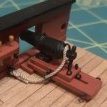
Making the thole pins was a little tedious, but not too bad. Parking out a piece of tape the correct length and rolling the knife across to score and break/cut them worked well. A few times I pushed a little too hard and the piece flew off into oblivion, but they give you enough material for many extras. Turning the square strip into a round dowel wasn't my favorite task, but it worked well enough. I just held it in one hand, sandpaper in the other and spun it around. Some sort of drill used as lathe would probably be nicer.
I actually made these first, but then decided to add the beckets first before fitting these thinking they would get in the way and I'd be snapping them off. I'm glad a did because the beckets were a pain.
First off, I saw many logs replacing the kit thread from something smaller. That was not my plan, I figured it could be scales as some thick 1.5" manila rope or something. The thread was tight, but I used the kit supplied drill bits to ream out the holes a little bit. I got the transom becket in without too much issue and started working on the bow/strake holes. The first one went in okay, but trying to get it through the second one that's threaded from the inside was the worst. Some notes on that:
The thread is 1.5mm if I remember right. The largest bit supplied in the toolkit is 1.4mm 🫠 The thread is nylon (I believe) and I didn't realize it at the time, but I far prefer other materials (natural). I spent about 1.5 hours over 3 different sessions fighting with this thread. I found it difficult to get a clean cut. In the end, I got frustrated enough at the bow that I ended up yanking it out and dug some 0.8mm cotton thread out of a different kit. This was a dream to work with by comparison, and obviously the smaller size allowed it to fit easier through the holes. It wasn't quite the color I wanted for it, but it was close enough and after finishing, I completely forgot about it.
The transom thread was cut off and replaced as well. Once I got the new thread in. I glued the knots with some diluted white glue and let it dry while I applied the thole pins.
I just need to fit the thwarts and I'm done. As I'm putting them in, something is wrong. The thwart on the fourth frame isn't sitting right. I thought maybe I mixed up the #2 and #4.... Impossible, I had that genius idea of taping them to the drawing in their correct locations! It did fit well in the #2 spot, but so did the #2 thwart.... No thwarts fit will in #4.
Then I realized what happened. Somehow I ended up beveling and finishing it upside down. When I flip it over, the frame slots line up. The paint job underneath was not as clean as the other side so I sanded it down and put another coat of paint. I sort of beveled it back in the other direction and dabbed some paint on. It fit in nicely and other than this record, nobody will ever know.
Fixed:
-
 tlevine got a reaction from robert952 in NRG Masting and Rigging Project
The NRG Masting and Rigging Project is now available for purchase in the NRG store. https://thenrgstore.org/collections/plans-and-projects/products/masting-and-rigging-kit The purpose of this kit is to teach the novice and intermediate model builder the basics of how to mast and rig a ship. The subject for this project is a waterline 1:48 scale cross-section of a late eighteenth-century British sloop of war. All the materials necessary to build the kit are included. We are pleased to provide the highest quality materials available. All of the line is from our sponsor Ropes of Scale. There are no square blocks in this kit!
For more details about the model, follow the build log.
-
tlevine reacted to giampieroricci in HMS PEGASUS by giampieroricci - Scale 1:36 - Swan-Class Sloop from plans by David Antscherl & Greg Herbert
I definitively fixed the swivel guns:
-
tlevine reacted to KORTES in Brig Le FAVORI 1806 by KORTES - 1:55
I need to blacken the metal and assemble.The carronades will have to be refined due to some mistakes in dimensions.
-
tlevine reacted to KORTES in Brig Le FAVORI 1806 by KORTES - 1:55
Lately , i dont have much free time. The work on the shipyard is going slow. Several shots of the work on the carronade carriage.
-
tlevine reacted to Rustyj in Sloop Speedwell 1752 by Rustyj - Syren Ship Model Company - 1:32 Scale - POF Sloop
I had mentioned earlier I had a medical issue that needed to be addressed. I met with the doctor and the
good news is I've been given a clean bill of health.
The bad news is I've been given a clean bill of health and have to return to work! 🤣
Work will slow considerably now. 😢
And the adventure continues,
I've now set 7 "tall" frames and 4 "short" frames. I've also added 2 sweep ports and 2 gun port sills on each side.
I used the supplied template to ensure that the spacing and height is correct.
As Mike mentioned earlier toothpicks were used on the jig for minor adjustments to fine tune the frame spacing.
My plan is to now add all the forward tall and short frames. I'll then use the template to adjust them to their correct position.
Once I confirm they are placed correctly, I'll start adding the sweep port blanks and the gun port sills.
-
tlevine reacted to Stuntflyer in Sloop Speedwell 1752 by Stuntflyer (Mike) - Ketch Rigged Sloop - POF
Upper bulwark planking
With the hull planking completed I decided to hold off on the wales and do some upper bulwark planking.
I made the hance pieces in three layers rather than two. I might have gotten away with two but it would have been close regarding width. I added the first two upper bulwark planks at the forecastle. Around the area of the bowsprit there is a tight 3/4" radius. Those 3/32" cedar caps are just sitting on top of the shear to give you an idea of what they would look like once I add them.
Mike
-
 tlevine got a reaction from BenD in Utrecht 1:72 by HiSModel
Our newest sponsor HiSModel is primarily a retailer of kits from several manufacturers. Their first in-house ship model kit is Yacht Utrecht 1746. Kurt was sent a copy of this kit for an open box review. The review can be seen in the latest issue of the Nautical Research Journal. I agreed to build the model from the perspective of a kit construction review.
First, some background information. The Dutch yachts were built to transport important individuals to official meetings and ceremonies. They were typically heavily decorated. According to HiS, this model is based on the original plans by the designer Pieter van Zwijndregt. A replica was built between 1998 and 2003. It’s primary use now is as an event space. https://statenjacht.nl/
As with any kit review, the following are photos of what is included in the kit. Not shown are flags, twenty-six resin decorations and rigging components (line, deadeyes, blocks, etc.). Yes, this is a plastic kit! I have not built any type of plastic kit in over 15 years, and that was an airplane I built to learn how to use an airbrush (and promptly threw away). And my first and last plastic ship model was Revell’s Constitution back in the late 70”s. It is a little hard to tell from the pictures but there is a lot of detail molded into the parts. All of the decorative elements are crisp. Unfortunately, the port head timbers were molded incorrectly. As this is a kit construction review, I decided to build it completely out of the box, with no modifications to the components provided.
The kit comes in two levels, basic and Premium. We were sent the Premium version. This has sewn sails, rather than a bolt of cloth, a wood deck, metal cannon in addition to the plastic ones, a few extra flags and a legal-sized poster of the boat. The decking is scribed for planking but the grain is very out of scale. The actual ship had a painted quarter deck but the kit included wood veneer without the planking scribes. The panel lines on the sails look good but the edge sewing is poorly done.
The instruction manual is designed so that there is minimal need for written instructions. There are multiple construction drawings which show where to install various parts and where to drill different diameter holes. There is one page containing six pictures of the completed model; everything else is computer generated.
Having already completed the model, I will give you my assessment before going on to the construction. This builds up into a nice-looking model. It is not without its problems, however. Some parts were not cast properly. The sails are of poor quality. There is insufficient rigging to complete the model. Some of the running rigging is shown as tarred line. The recommended paint colors do not match the replica ship. Finally, the instruction manual has a lot to be desired. I would not have known how to install the leeboards if I did not have Angarfarther’s build log to refer to. https://modelshipworld.com/topic/10401-statenjacht-utrecht-by-angarfather-136/#comment-311620 On the positive side, the resin castings are incredible. HiS should sell these separately for anyone else who wants to build Utrecht at 1:72 scale. The included blocks are the best commercial blocks I have seen. The line is fuzz-free.
I cannot recommend this kit as something to be built out of the box. There are just too many small issues. I also do not recommend the Premium version. The coarse deck grain is distracting, the sails are of poor quality and the metal guns are not necessary. The plastic guns included are of very high quality and do not need replacing with metal. But for someone who would like to kit-bash this model, I strongly recommend the kit. It is not overly large (35 cm long and tall) and I was able to complete her in just over one hundred hours, including research. The condensed build log can be found under the kits build section.
-
 tlevine got a reaction from archjofo in NRG Rigging Project by tlevine - FINISHED
To prevent damage, the top rail was made last. There are four balustrades that fit into the holes previously made in the top and a top rail. The rail extended almost to the edges of the top and is 4” wide. This was cut from 1/32” sheet wood and the edges were smoothed over. The rail was placed on the top’s gunwale and the locations of the balustrade holes were transferred to it.
The balustrades are two feet long and 2 inches square. The two ends of the balustrade are square and the center section is round. You can see the transition marks for the top and bottom pins, and between the square and round sections drawn onto the wood. I used an 11 blade, files and sandpaper to round the center section. The transition from square to round was shaped with a half-round file. The end pins are square.
The balustrades were inserted into the rail after enlarging the drill holes. Then they were glued into the holes in the top. The rail is angled 90 degrees to the water line. Once dry, the protruding pins were sanded flush with the rail.
As a final step, I applied mahogany veneer to the exposed frames. All that was left was to clean things up. Thank you for following along!
-
 tlevine got a reaction from CiscoH in NRG Rigging Project by tlevine - FINISHED
To prevent damage, the top rail was made last. There are four balustrades that fit into the holes previously made in the top and a top rail. The rail extended almost to the edges of the top and is 4” wide. This was cut from 1/32” sheet wood and the edges were smoothed over. The rail was placed on the top’s gunwale and the locations of the balustrade holes were transferred to it.
The balustrades are two feet long and 2 inches square. The two ends of the balustrade are square and the center section is round. You can see the transition marks for the top and bottom pins, and between the square and round sections drawn onto the wood. I used an 11 blade, files and sandpaper to round the center section. The transition from square to round was shaped with a half-round file. The end pins are square.
The balustrades were inserted into the rail after enlarging the drill holes. Then they were glued into the holes in the top. The rail is angled 90 degrees to the water line. Once dry, the protruding pins were sanded flush with the rail.
As a final step, I applied mahogany veneer to the exposed frames. All that was left was to clean things up. Thank you for following along!
-
tlevine reacted to ferretmary1 in NRG Rigging Project by tlevine - FINISHED
17 people have purchased the kit so far (including you). Yours was shipped out less than an hour ago.
Have fun with the build!
Mary
-
tlevine reacted to ChuckCHS in NRG Rigging Project by tlevine - FINISHED
I've just purchased this amazing teaching tool. Should arive in just a few days. Just wondering if others have done the same.
Chuck
-
 tlevine got a reaction from Mr Whippy in NRG Rigging Project by tlevine - FINISHED
To prevent damage, the top rail was made last. There are four balustrades that fit into the holes previously made in the top and a top rail. The rail extended almost to the edges of the top and is 4” wide. This was cut from 1/32” sheet wood and the edges were smoothed over. The rail was placed on the top’s gunwale and the locations of the balustrade holes were transferred to it.
The balustrades are two feet long and 2 inches square. The two ends of the balustrade are square and the center section is round. You can see the transition marks for the top and bottom pins, and between the square and round sections drawn onto the wood. I used an 11 blade, files and sandpaper to round the center section. The transition from square to round was shaped with a half-round file. The end pins are square.
The balustrades were inserted into the rail after enlarging the drill holes. Then they were glued into the holes in the top. The rail is angled 90 degrees to the water line. Once dry, the protruding pins were sanded flush with the rail.
As a final step, I applied mahogany veneer to the exposed frames. All that was left was to clean things up. Thank you for following along!
-
tlevine got a reaction from archjofo in NRG Rigging Project by tlevine - FINISHED
The truss pendants are paired ropes that hold the yard against the mast. These are made from twenty feet of 4” rope with a double block stropped on one end and a thimble on the other. The end with the thimble is seized onto the yard. I spliced a thimble into one end of the line and seized the pendant onto the yard inside the quarter block, keeping the thimble on the aft side of the yard. I rotated the yard 180 degrees to gain better access to the aft side of the yard.
Once both pendants were attached to the yard, I ran the line from the starboard pendant through the top of the port pendant thimble; the process was repeated with the port pendant, passing it through the top of the starboard thimble. The result is a crossing of the two lines on the aft side of the mast.
Three-millimeter double blocks were stropped on the ends of the pendants for the pendant falls. In the picture below, the outer lines are the jeer tyes and the longer inner ones are the pendants.
The lower blocks for the pendant and jeer falls attach to the eyebolts on the mast partners. The strop for the blocks is spliced, with a loop seized at each end. The lower loop is fitted with a hook and the falls will be attached to the upper loop. It took a few tries to make hooks that looked realistic. After they were made, I opened the loop and inserted it into one of the block loops. The rope for the falls passes through the other loop and is spliced to itself to secure it.
The jeer tye falls are 2” rope. After securing it to the lower tye falls block loop, the line was passed back and forth through the upper and lower blocks and hooked to the block on the aft eyebolt, adjusting the length of rope as necessary to get a snug but not too tight line. I wrapped the line a few times around the bits and taped the ends to the back of the last frame. This allowed me to easily adjust the tension.
The pendant tye falls were rove the same way. The rope for the pendant falls is 1 3/4”. The ends were taped to frame 1. I tightened all the lines and let the model sit for a day to allow the rope to stretch from the tension. The lines were adjusted and retapes them to the frames. The jeer tye falls were finished off by making rope coils to go over the bit pin. I made my coils by taking a piece of line and wrapping it around the jaws of a caliper. The line was removed by closing the jaws. A few turns of line were wrapped around the middle of the coil.
Steel states that both the jeer tye and pendant falls tie off to bits. I tied the jeer tye falls to the bits and the pendant falls to itself to prevent the lines from rubbing against each other and to show an alternate way to tie off a line. The rope coils for the pendant falls were made on the model. My rope coil is 3.5’ long and the wrap is 4’ up from the deck. That completes the rigging.
-
tlevine reacted to No Idea in Le Rochefort by No Idea - 1/24th Scale - First POF Build
Hi All
I've not checked in for a while as I cannot get any work done on my ship at the moment. My workshop has been turned into a storage room due to a contractor letting us down to fit a complete bathroom - The bathroom is in my workshop - such is life. It looks like it's going to be this way until October so I will have to be patient.
I did start the planking and it was going on very nicely following my marking out. I did find it quite hard though as the planks are 3.2mm thick so require a lot of clamps. Here's a good indicator - the coin is a pound coin.
The bow and stern required spiling as otherwise the planks just don't fit and will not sit flat on the frames.
Now here is where I hit a really big problem. If you look at the above photo's you can see that I used a black toolmakers clamp. It was brand new and did the job great. Unfortunately what with the moisture and heat in the planks the black oil coating ran straight onto the ends of 4 planks. It didn't do this for the first 3 planks and then Boom!
I tried every kind of solvent to try and remove the blackness - it was so bad at the tips that I tried to cut away part of the tips and replace them with small scraps. I even tried diluted bleach but the results were very bad - see below (I had already removed one plank). Basically at this point I was bodging it up!
So I realised that I was trying to cut corners and I could not leave it looking like that. I removed the stained planks and that's where I'm at now. It's going to need a really good clean up but thats OK. I also have to damaged planks to use a templates too. I'll recut the rabbit and clean up the stem at the same time.
As soon as I get my workshop back I'll be at it again and hopefully never make the same mistake again. If you've followed my build this sort of thing is pretty much on par for me
Thanks Mark
-
tlevine reacted to Waldemar in Samuel 1650 – a Dutch mid-17th century trader
This thread will show the result of a conceptual interpretation and a partial reconstruction attempt of an important, very well-preserved wreck of a mid-17th century Dutch cargo ship, excavated in the Ijsselmeer basin in the north of the Netherlands. The ship has been identified as the Samuel, serving the trade with the Iberian peninsula, among others.
A very extensive archaeological record of the shipwreck can be found at:
https://beeldbank.cultureelerfgoed.nl/rce-mediabank/?mode=gallery&view=horizontal&q=e81&page=1&record=bb0c9df7-b54d-2770-7cff-2d946e245039&sort=order_s_objectnummer%20asc
Shipwreck E81 (Samuel 1650), photo by Jan Rypma
Ship’s main dimensions (as recorded, read or interpreted):
Breadth: 26 feet
Length of keel: 78 feet (3 x breadth)
Length between posts: 91 feet (3.5 x breadth)
Depth in hold: 10 feet
* * *
Keel assembly, lengthwise division & main design lines
Ratio of sternpost rake to stempost rake: 1:6 (note: stempost rake measured from the point where the rabbet line crosses the upper edge of the keel and enters the stempost)
Height of sternpost: ~2 x height of tuck (note: height of tuck at the waterline level)
Height of stempost: height of sternpost + 1 foot
Longitudinal position of master frame: 1/3 of keel length (see diagram for the determination method)
Note: the radius of the stempost in the diagram relates to the arc of the upper rabbet line.
According to the archaeological record, the following relationships and design sequence of Samuel 1650 have been found or guessed:
– the waterline level was set at eight feet, corresponding to the height of tuck (or vice versa), horizontally (as in the diagram) or, alternatively, angled to the lesser height of 7 feet at the bow,
– the length of the waterline (not including the posts) has been divided into seven parts (with a possible subdivision of 14),
– the line of the floor was set, terminating aft at the height of tuck and, at the fore, one foot below the horizontal waterline level (or at the intersection of the design waterline with the stempost for angled waterline); at the master frame deadrise has been fixed at three inches,
– the height of the greatest breadth at the master frame is 1/10 of the total length of the hull (i.e. between posts), about one foot above the design waterline,
– the wales are perfectly parallel to the line of greatest breadth (scheerstrook, scheergang).
Of note is the extensive use of logarithmic curves to define the shapes of the main design lines. These are one of the easiest types of curves (or maybe better: transformation) to use in practice, especially as they are ideally suited to achieving the contours of the frames straight away on the mould loft with a trivial simplicity, and without any real need to make any scale drawings on paper in advance. Essentially, no knowledge of theory is required, just familiarity with straightforward division operations is enough.
So much for the essentials of this rather simple design (in conceptual terms).
* * *
Cross-sections
Dimensions of master frame components (as recorded, read or interpreted):
Width of the „flat”: ~17 1/3 (2/3 x max. breadth)
Deadrise (at the master frame): 3 inches
Design depth: ~9 feet (1/10 x length)
Futtock sweep: variable radius (equal to respective breadth) or fixed radius (equal to max. breadth); note: both variants result in almost indiscernible shapes for this shipwreck,
Bilge sweep: 4 1/3 (fixed radius; 1/6 x max. breadth)
Reconciling sweep: 17 1/3 (fixed radius; 2/3 x max. breadth)
It can also be added that the transverse contours of the „flat” for all leading frames are straight lines, except for the last leading frame it is in the form of an circular arc (note: on the diagram below one more frame was drawn between the last leading frame and the sternpost). Employment of the arc is for the smooth transition of the hull surfaces toward the sternpost, providing better waterflow for at least acceptable rudder efficiency.
* * *
Possible appearance
The graphic below shows a hypothetical appearance of the Samuel 1650 once its upperworks have been recreated. The Samuel 1650 is actually almost the smallest ship for which the two-deck configuration was used. The distance between decks was taken from Grebber's table, reproduced in both Witsen's 1671 and van Yk's 1697 works. This feature, taken together with the relatively small size of the ship, make Samuel's silhouette quite tall, and despite the smallest distance adopted between these decks (about 4½ feet).
The very full shape of the underwater part of the hull, suitable for a cargo ship, is also evident. Taken together with the high freeboard, this must have made the ship very leeward, which ultimately surely contributed to her disaster, but also preserved her to our times.
The position of the masts, or rather the foremast and mainmast, was taken from the shipwreck documentation, but it must be said that it is altogether quite typical: the mainmast at the middle of the keel and the foremast above the gripe, i.e. above the junction of the keel with the stem post.
Also below are some graphics showing ships of a similar nature. While not all from the Samuel's particular period, especially the last two, they still can be relevant for various details, but also to get a better feel for this vessel’s general specifics (Dutch archives).
* * *
Reconstruction hull lines
As the below drawings are reconstruction plans, there is no need to take them too literally. For example, a 'perforated' railing may be added in the aft part to make the sheer of the ship more attractive, or the upper edge of the stern 'mirror' may be made as an arc. Some more wales with a smaller cross section above the three main ones drawn on the plan should actually be attached as well, and the sternpost possibly shortened a little, roughly to the height of the wing transom, for free entry of the tiller into the hull, etc.
The correct arrangement of the garboard strakes in Dutch convention is well shown below in the documentation of the Samuel 1650 shipwreck. Actually, in the central part of the hull, the garboard strakes are not in contact with the frame timbers at all. On the plans the garboard strakes are not drawn because these plans show the contours of the frames and not the planking. On the sheer view, however, both rabbet lines are plotted, just for this purpose.
The hull lines has been checked for fairness (as opposed to actually forming the shapes) with diagonals and waterlines.
Thank you for your attention,
Waldemar Gurgul
-
 tlevine got a reaction from tmj in NRG Rigging Project by tlevine - FINISHED
To prevent damage, the top rail was made last. There are four balustrades that fit into the holes previously made in the top and a top rail. The rail extended almost to the edges of the top and is 4” wide. This was cut from 1/32” sheet wood and the edges were smoothed over. The rail was placed on the top’s gunwale and the locations of the balustrade holes were transferred to it.
The balustrades are two feet long and 2 inches square. The two ends of the balustrade are square and the center section is round. You can see the transition marks for the top and bottom pins, and between the square and round sections drawn onto the wood. I used an 11 blade, files and sandpaper to round the center section. The transition from square to round was shaped with a half-round file. The end pins are square.
The balustrades were inserted into the rail after enlarging the drill holes. Then they were glued into the holes in the top. The rail is angled 90 degrees to the water line. Once dry, the protruding pins were sanded flush with the rail.
As a final step, I applied mahogany veneer to the exposed frames. All that was left was to clean things up. Thank you for following along!