

tlevine
-
Posts
1,960 -
Joined
-
Last visited
Reputation Activity
-

 tlevine got a reaction from herask in HMS Atalanta 1775 by tlevine - FINISHED - 1:48 scale - from TFFM plans
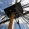
Beam set 7 includes the opening for the fore hatch. These carlings are a little larger than the standard ones. As I am building the lower deck structures as I move aft, it was time to build the aft sail room. The fore sail room is one of the small rooms on the port side near beam set 4. This was a fun little structure to make. The lateral walls have louvers to allow ventilation into the room. I do not own a mill so the mortises for the louvers were made with an 11 blade. On Atalanta, the door into this room is a slider, not a hinged door. Consequently, the door must be made wider than the opening and it will be on the outside wall of the sail room. There is a pillar on the inside wall precluding placing the door there. Not having built a sliding door before, I went over to the local stable and looked at my horse's stall door. The latch is a L-shaped bolt on the door with a U-shaped piece of metal on the door frame to receive the bolt. The bolt measured 3" x 4" x 3/8". This would require making a u-shaped channel 0.01" square. Needless to say, this is well beyond my skill set so I have a flat piece of metal on the door frame representing it instead. Decking was placed under the assembly on the starboard side. The last two pictures show the sail room assembly before and after a coat of finish.
-
 tlevine got a reaction from bdgiantman2 in La Créole 1827 by archjofo - Scale 1/48 - French corvette
The amount of detail is incredible. They look like they are ready to fire!
-
 tlevine got a reaction from paulsutcliffe in HMS Atalanta 1775 by tlevine - FINISHED - 1:48 scale - from TFFM plans
A delayed thank you to Maurey and Pavel. Druxey, the tracks are now installed and, like so many details that we add, are now almost invisible! But we all know they are there...
Beam sets 9 and 10 are in place. The only unusual items are the opposed lodging knees at the dead flat. I did not have thick enough wood with me this week to make them, so they will be installed next week. They will be identical to the ones on the lower deck. Look at page 10 of this build to see how they are shaped.
-
 tlevine reacted to archjofo in La Créole 1827 by archjofo - Scale 1/48 - French corvette
Hello,
this carronades are smaller than most people think it ...
Look for yourself ...
-
 tlevine got a reaction from Elmer Cornish in HMS Atalanta 1775 by tlevine - FINISHED - 1:48 scale - from TFFM plans
A delayed thank you to Maurey and Pavel. Druxey, the tracks are now installed and, like so many details that we add, are now almost invisible! But we all know they are there...
Beam sets 9 and 10 are in place. The only unusual items are the opposed lodging knees at the dead flat. I did not have thick enough wood with me this week to make them, so they will be installed next week. They will be identical to the ones on the lower deck. Look at page 10 of this build to see how they are shaped.
-
 tlevine got a reaction from sonicmcdude in HMS Atalanta 1775 by tlevine - FINISHED - 1:48 scale - from TFFM plans
A delayed thank you to Maurey and Pavel. Druxey, the tracks are now installed and, like so many details that we add, are now almost invisible! But we all know they are there...
Beam sets 9 and 10 are in place. The only unusual items are the opposed lodging knees at the dead flat. I did not have thick enough wood with me this week to make them, so they will be installed next week. They will be identical to the ones on the lower deck. Look at page 10 of this build to see how they are shaped.
-
 tlevine got a reaction from Richard Griffith in HMS Atalanta 1775 by tlevine - FINISHED - 1:48 scale - from TFFM plans
A delayed thank you to Maurey and Pavel. Druxey, the tracks are now installed and, like so many details that we add, are now almost invisible! But we all know they are there...
Beam sets 9 and 10 are in place. The only unusual items are the opposed lodging knees at the dead flat. I did not have thick enough wood with me this week to make them, so they will be installed next week. They will be identical to the ones on the lower deck. Look at page 10 of this build to see how they are shaped.
-
 tlevine got a reaction from Chuck in HMS Atalanta 1775 by tlevine - FINISHED - 1:48 scale - from TFFM plans
A delayed thank you to Maurey and Pavel. Druxey, the tracks are now installed and, like so many details that we add, are now almost invisible! But we all know they are there...
Beam sets 9 and 10 are in place. The only unusual items are the opposed lodging knees at the dead flat. I did not have thick enough wood with me this week to make them, so they will be installed next week. They will be identical to the ones on the lower deck. Look at page 10 of this build to see how they are shaped.
-
 tlevine got a reaction from Wintergreen in HMS Atalanta 1775 by tlevine - FINISHED - 1:48 scale - from TFFM plans
A delayed thank you to Maurey and Pavel. Druxey, the tracks are now installed and, like so many details that we add, are now almost invisible! But we all know they are there...
Beam sets 9 and 10 are in place. The only unusual items are the opposed lodging knees at the dead flat. I did not have thick enough wood with me this week to make them, so they will be installed next week. They will be identical to the ones on the lower deck. Look at page 10 of this build to see how they are shaped.
-
 tlevine got a reaction from harvey1847 in HMS Atalanta 1775 by tlevine - FINISHED - 1:48 scale - from TFFM plans
A delayed thank you to Maurey and Pavel. Druxey, the tracks are now installed and, like so many details that we add, are now almost invisible! But we all know they are there...
Beam sets 9 and 10 are in place. The only unusual items are the opposed lodging knees at the dead flat. I did not have thick enough wood with me this week to make them, so they will be installed next week. They will be identical to the ones on the lower deck. Look at page 10 of this build to see how they are shaped.
-
 tlevine got a reaction from Jason in HMS Atalanta 1775 by tlevine - FINISHED - 1:48 scale - from TFFM plans
A delayed thank you to Maurey and Pavel. Druxey, the tracks are now installed and, like so many details that we add, are now almost invisible! But we all know they are there...
Beam sets 9 and 10 are in place. The only unusual items are the opposed lodging knees at the dead flat. I did not have thick enough wood with me this week to make them, so they will be installed next week. They will be identical to the ones on the lower deck. Look at page 10 of this build to see how they are shaped.
-
tlevine reacted to rlb in US Brig Oneida 1809 by rlb - The Lumberyard - 1:48 scale - POF - Lake Ontario Warship
Continuing on with the aft coaming area--
Here the blackened brass rods are fit to the skylight sashes, and dry fit on the frame--
The skylight hinges are trimmed short. You can see where I've cut a small mortice in the skylight for them to sit--
The binnacle is started from a solid block. I've also epoxied "glass" (cut from the plastic address window of an envelope) on the underside of one skylight sash--
The center is cut out of the binnacle block. I've glued the hinges onto the skylight sashes, and you can see the effect of the glass in the skylight--
A top is made for the binnacle, and holes are drilled in the center. A larger size from the top (the width of the compass) and a smaller one all the way through, to push the compass back out from below during test fittings--
In this photo you can see two sections of brass tube soldered together. Inner tube will form a seat to glue the compass face to. For the compass, I smeared the corner of a piece of white card stock with some stain, so it wouldn't be so bright. Then I epoxied some "glass" to it. After not doing a very good job cutting a tiny circle (that's where that little cut out in the corner came from), I got the idea to file the end of a brass tube to make a punch--
The punch worked great, but I ended up making another from the next smaller tube, as this left a little gap between the brass tube and the compass face--a hint of a gimble assembly--
After much frustration and delay with the companionway doors (re-gluing hinges multiple times), everything is finally there. Some is glued, some is just sitting (the binnacle). There's no hardware (i.e. latches, knobs, etc.) on the companionway doors, or the binnacle doors. I'm still deciding whether to add anything to those. I have a hard time controlling epoxy smears, and my CA has all gone bad, so for now they'll stay as is--
The binnacle is pretty short. It's that way to stay below the companionway top, which overhangs its sides about and inch and a half.
I think the visibility through the "glass" is just about perfect--
A longer "context" shot. The deck is looking a lot more finished!
Ron
-
tlevine got a reaction from paulsutcliffe in HMS Atalanta 1775 by tlevine - FINISHED - 1:48 scale - from TFFM plans
Beam set 7 includes the opening for the fore hatch. These carlings are a little larger than the standard ones. As I am building the lower deck structures as I move aft, it was time to build the aft sail room. The fore sail room is one of the small rooms on the port side near beam set 4. This was a fun little structure to make. The lateral walls have louvers to allow ventilation into the room. I do not own a mill so the mortises for the louvers were made with an 11 blade. On Atalanta, the door into this room is a slider, not a hinged door. Consequently, the door must be made wider than the opening and it will be on the outside wall of the sail room. There is a pillar on the inside wall precluding placing the door there. Not having built a sliding door before, I went over to the local stable and looked at my horse's stall door. The latch is a L-shaped bolt on the door with a U-shaped piece of metal on the door frame to receive the bolt. The bolt measured 3" x 4" x 3/8". This would require making a u-shaped channel 0.01" square. Needless to say, this is well beyond my skill set so I have a flat piece of metal on the door frame representing it instead. Decking was placed under the assembly on the starboard side. The last two pictures show the sail room assembly before and after a coat of finish.
-
tlevine reacted to rlb in US Brig Oneida 1809 by rlb - The Lumberyard - 1:48 scale - POF - Lake Ontario Warship
Today, I did a lot of brass work, and soldering, in working on the pumps.
My basis-of-design is from Charles G. Davis in "The Built-up-Ship Model"--
Here are most of the pieces needed, various diameters of brass tubing, rod, and bar stock--
First I soldered some bent rod to scores cut in the barrel of the upper valve pieces--
These were then filed back to the diameter of the tubing--
So that the valve would slide into the pump chamber--
Loops were made at the end of lengths of brass rod, for the plunger pieces--
Out of bar stock, the rocker arm was rough cut, and filed--
Here are the pieces, just about all assembled--
The "sockets" on the ends of the rocker arm are some square tube that I hammered down a little to make it rectangular, and then soldered to the rocker arm.
After determining the correct length of the plunger rods, I soldered u-shaped attachments. I had to do this three times before I got a solder joint that held--
I also had to redo the flange pieces for the tubes. I ended up hammering down a ring cut from a larger size tube, and then, since it wasn't perfectly round after the hammering, I filed it inside and out so it would fit the tube and be round--it looks much better than what I had before--
Next will be blackening and assembling the pumps.
Ron
-
 tlevine got a reaction from Jeronimo in HMS Atalanta 1775 by tlevine - FINISHED - 1:48 scale - from TFFM plans
A delayed thank you to Maurey and Pavel. Druxey, the tracks are now installed and, like so many details that we add, are now almost invisible! But we all know they are there...
Beam sets 9 and 10 are in place. The only unusual items are the opposed lodging knees at the dead flat. I did not have thick enough wood with me this week to make them, so they will be installed next week. They will be identical to the ones on the lower deck. Look at page 10 of this build to see how they are shaped.
-
 tlevine got a reaction from garyshipwright in HMS Atalanta 1775 by tlevine - FINISHED - 1:48 scale - from TFFM plans
A delayed thank you to Maurey and Pavel. Druxey, the tracks are now installed and, like so many details that we add, are now almost invisible! But we all know they are there...
Beam sets 9 and 10 are in place. The only unusual items are the opposed lodging knees at the dead flat. I did not have thick enough wood with me this week to make them, so they will be installed next week. They will be identical to the ones on the lower deck. Look at page 10 of this build to see how they are shaped.
-
tlevine reacted to Remcohe in HMS Kingfisher 1770 by Remcohe - 1/48 - English 14-Gun Sloop - POF
Go for it guy's make lots and lots of pins They are key to position parts temporarily, I don't exaggerate but I think any particular beam in this build is taken in and out at least 100 times to position parts, mark mortices etc etc.
So today I did a little detailing of the gratings. I simulated the pins that were used by making small holes with a needle and then taking the same needle tip loaded with graphite to enhance the holes. This really takes your mind off-line after a busy day
For comparison, the 'big' bolts on the corners are 0,4 mm
Remco
-
tlevine reacted to Remcohe in HMS Kingfisher 1770 by Remcohe - 1/48 - English 14-Gun Sloop - POF
Thanks Piet.
Jan what can I say, the MSW Oracle didn't answer and I went forward taking a 50% bet I got it right
Meanwhile, more knee's opposing knee's gratings and so on. Everything is loosely fitted before marking the mortices for the ledges. Doing tasks in batches certainly speeds things up.
Remco
-
tlevine reacted to SJSoane in HMS Bellona 1760 by SJSoane - Scale 1:64 - English 74-gun - as designed
Hi everyone,
This weekend, I pushed along to finish the aft end of the gundeck (all but ledges). The first photo shows using a caul shaped to the fore and aft camber of the gundeck, which I used to level the beams as I glued them in place. Clamping the beams up to the caul ensured that they are all precisely level on the upper surface, where it counts.
I then worked on the carlings. I found an easy way to measure the angle of the end of each carling in a beam, with an angle gauge. i could then use the gauge to set the angle of the miter gauge on the sanding machine, for precise results, and flip it over to reverse the miter gauge and sand the symmetrically opposite carling in the same bay. Systematically working aft and from outboard to the center, I got them all done in a day. I still need to cut mortises for ledges in the carlings before they can be glued. I got progressively better at this as I worked along. The carling fair well fore and aft, with only one joint needing a slight adjustment from my original mortise cuts.
I also built the mizen mast core in anticipation of building the partners, and found an easy way to set the diameters at the 4 quarters, using a proportional divider set to two divisions. I set the long legs on the ruler for the total diameter at any point, and then used the short legs to mark off either side of the center line. It saved a lot of time.
I made the fore and aft standard fitting up against the wing transom and stern post. It took some fiddling to match angles and cut the slot for the wing transom. But very satisfying after all of these years to see that finishing up the aft deck. You can see on the starboard side of the aft gun deck, my first efforts at working out how a knee would finish up the deck at the rounded aft end. I have no drawings that show what this knee would look like but there has to be one to provide a landing for decking in the corner, before the decking can land on the deck transom. I can't believe that the decking would just land on the inner side of the aftmost frames with no support under it. Does anyone recall seeing a drawing of what happens here?
Best wishes,
Mark
-
tlevine reacted to Jeronimo in LE BONHOMME RICHARD by Jeronimo - FINISHED
Hi friends,
construction and installation of the pumps.
Karl
T e i l 3 8
-
 tlevine got a reaction from Geoff Matson in Micro drill holders
Ben,
I always had problems with the after market micro chucks for the Dremel. Drill Bit City sells resharpened carbide micro drills that are fantastic. (And the prices are similar to HSS bits.) Because they are carbide, they are more brittle and work best with a steady hand or in a drill press. They have a standard shaft that fits into a regular collet for the Dremel, resulting in much less wobble and a true-to-size hole. Usual disclaimers.
-
tlevine reacted to dvm27 in Speedwell 1752 by dvm27 (Greg Herbert) - FINISHED - Ketch Rigged Sloop
It's been a few months since I've posted an update to my build log of Speedwell. All four platforms are now in place, as are the shot locker and galley stove. Besides the wales, there will be very little external planking in order not to cover those wacky, fun to make shifted and cast toptimbers.
The single wale was made of holly and stained with Fiebings black leather dye (off the model).
The two completed fore platforms
The very small shot lockers accommodate the three pound cannon balls
The very small shot lockers accommodate the three pound cannon balls
The galley stove was made of brass over a holly plug
-
tlevine got a reaction from Elmer Cornish in HMS Atalanta 1775 by tlevine - FINISHED - 1:48 scale - from TFFM plans
Beam set 7 includes the opening for the fore hatch. These carlings are a little larger than the standard ones. As I am building the lower deck structures as I move aft, it was time to build the aft sail room. The fore sail room is one of the small rooms on the port side near beam set 4. This was a fun little structure to make. The lateral walls have louvers to allow ventilation into the room. I do not own a mill so the mortises for the louvers were made with an 11 blade. On Atalanta, the door into this room is a slider, not a hinged door. Consequently, the door must be made wider than the opening and it will be on the outside wall of the sail room. There is a pillar on the inside wall precluding placing the door there. Not having built a sliding door before, I went over to the local stable and looked at my horse's stall door. The latch is a L-shaped bolt on the door with a U-shaped piece of metal on the door frame to receive the bolt. The bolt measured 3" x 4" x 3/8". This would require making a u-shaped channel 0.01" square. Needless to say, this is well beyond my skill set so I have a flat piece of metal on the door frame representing it instead. Decking was placed under the assembly on the starboard side. The last two pictures show the sail room assembly before and after a coat of finish.
-
 tlevine got a reaction from Kevin in HMS Atalanta 1775 by tlevine - FINISHED - 1:48 scale - from TFFM plans
Beam set 7 includes the opening for the fore hatch. These carlings are a little larger than the standard ones. As I am building the lower deck structures as I move aft, it was time to build the aft sail room. The fore sail room is one of the small rooms on the port side near beam set 4. This was a fun little structure to make. The lateral walls have louvers to allow ventilation into the room. I do not own a mill so the mortises for the louvers were made with an 11 blade. On Atalanta, the door into this room is a slider, not a hinged door. Consequently, the door must be made wider than the opening and it will be on the outside wall of the sail room. There is a pillar on the inside wall precluding placing the door there. Not having built a sliding door before, I went over to the local stable and looked at my horse's stall door. The latch is a L-shaped bolt on the door with a U-shaped piece of metal on the door frame to receive the bolt. The bolt measured 3" x 4" x 3/8". This would require making a u-shaped channel 0.01" square. Needless to say, this is well beyond my skill set so I have a flat piece of metal on the door frame representing it instead. Decking was placed under the assembly on the starboard side. The last two pictures show the sail room assembly before and after a coat of finish.
-
tlevine got a reaction from Richard Griffith in HMS Atalanta 1775 by tlevine - FINISHED - 1:48 scale - from TFFM plans
Beam set 7 includes the opening for the fore hatch. These carlings are a little larger than the standard ones. As I am building the lower deck structures as I move aft, it was time to build the aft sail room. The fore sail room is one of the small rooms on the port side near beam set 4. This was a fun little structure to make. The lateral walls have louvers to allow ventilation into the room. I do not own a mill so the mortises for the louvers were made with an 11 blade. On Atalanta, the door into this room is a slider, not a hinged door. Consequently, the door must be made wider than the opening and it will be on the outside wall of the sail room. There is a pillar on the inside wall precluding placing the door there. Not having built a sliding door before, I went over to the local stable and looked at my horse's stall door. The latch is a L-shaped bolt on the door with a U-shaped piece of metal on the door frame to receive the bolt. The bolt measured 3" x 4" x 3/8". This would require making a u-shaped channel 0.01" square. Needless to say, this is well beyond my skill set so I have a flat piece of metal on the door frame representing it instead. Decking was placed under the assembly on the starboard side. The last two pictures show the sail room assembly before and after a coat of finish.