Hubac's Historian
-
Posts
3,314 -
Joined
-
Last visited
Content Type
Profiles
Forums
Gallery
Events
Everything posted by Hubac's Historian
-
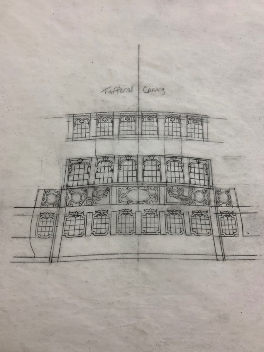
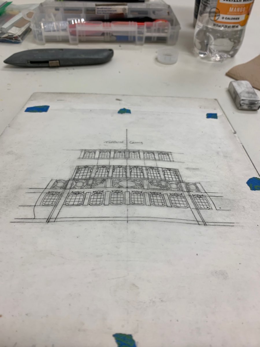
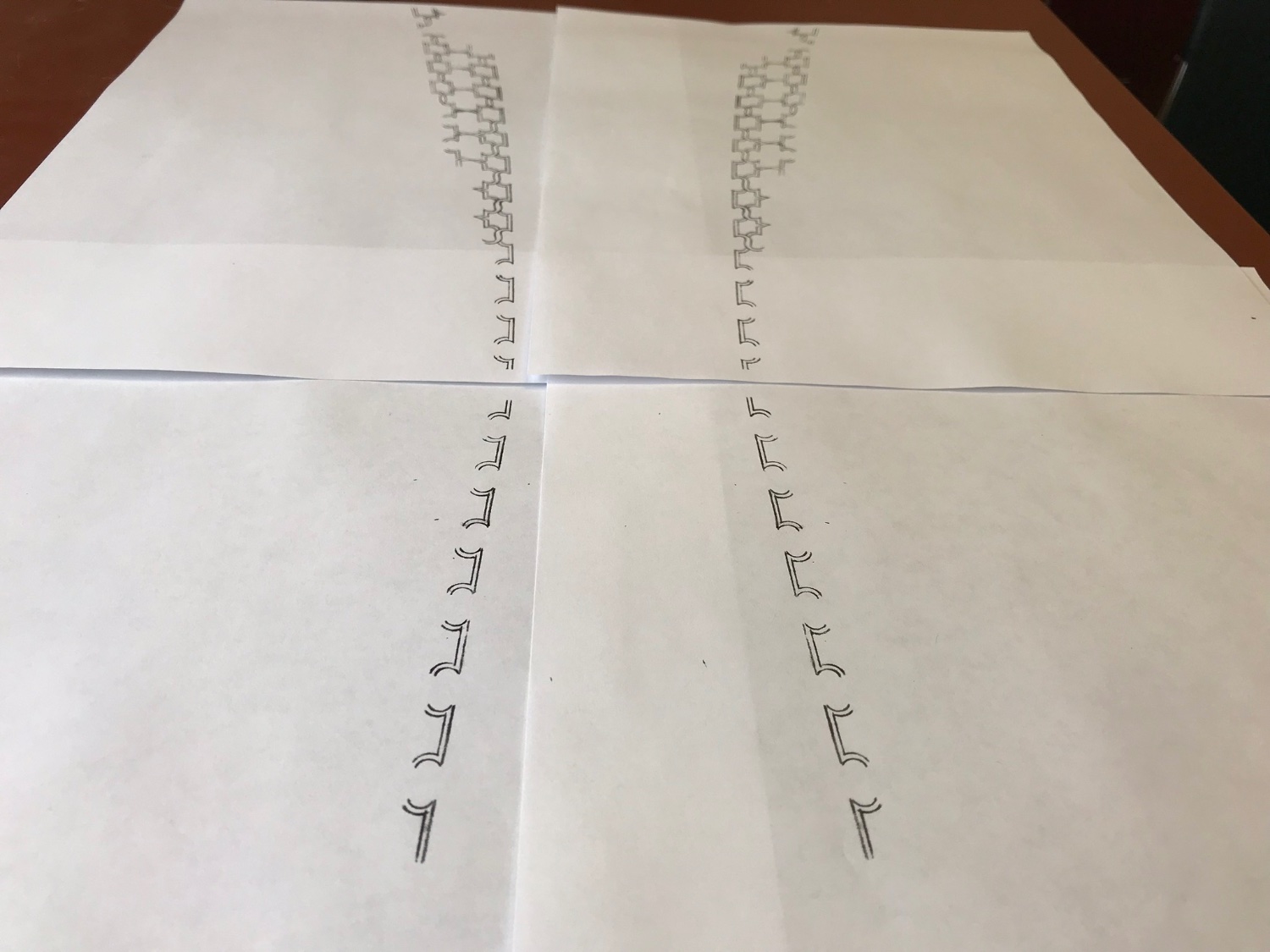
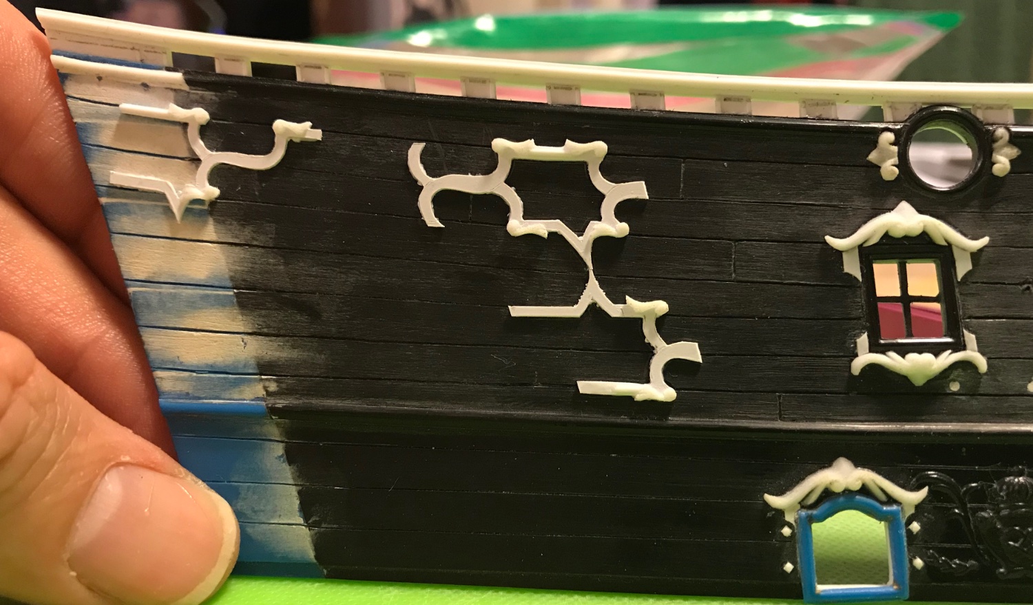
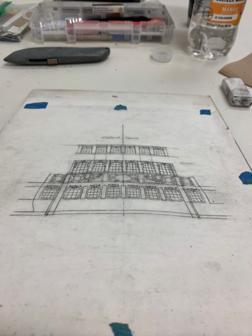
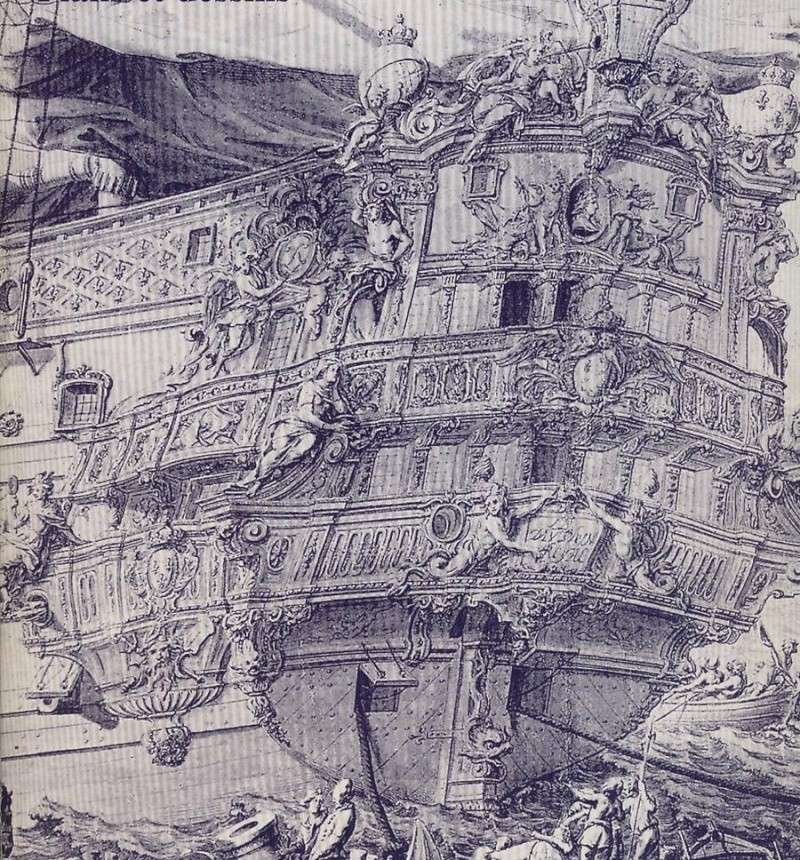
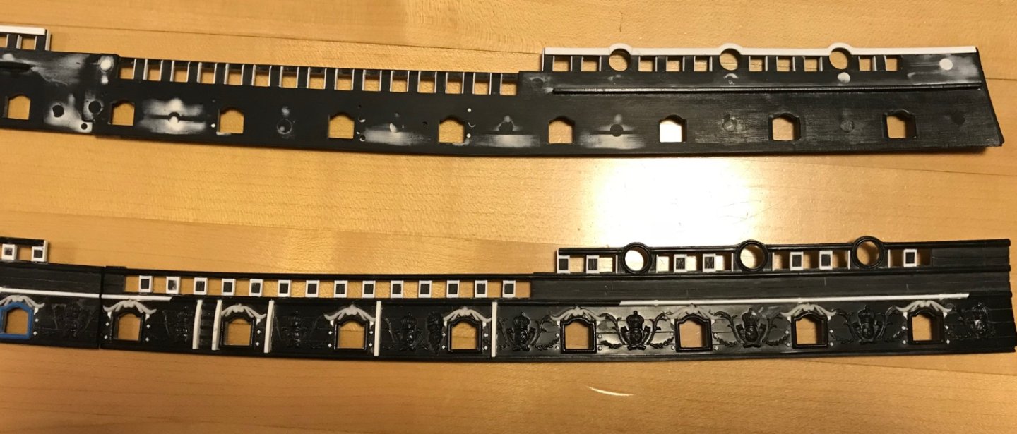
 Michael and T_C - thank you very much! And, of course, thank you all for the likes and stopping by. Painting on the headrails continues. I’ve been through a round of re-touches and I’ve applied the distress wash. If I may so so, they look pretty good. The wash does a world of wonders. Pics to follow after gilding and grey-washing of the horses. I have also been busy drafting the third and final tier of stern lights. This was interesting, for me, as I had to remind myself of a few important design considerations. Firstly, I had increased the camber of the middle-tier of lights because the arc of the lower tier would have appeared too flat (in a shorter arc segment), if I had remained consistent. It seemed like an additional increase in camber, for the top tier would not pay dividends, so I maintained the middle arc of camber. I believe this will frame a nice upward sweep to the tafferal frieze for Apollo and his chariot. What I am aiming for is best expressed by the magnificent work of Olivier Gatine on his magnificent La Belle. There is an elegance of line, IMO, that really elevates this model above any other attempt I have seen of this subject - and there have been many really good ones. He really captures something, here. I can only dare to dream and attempt to emulate the finer points of his craft. Here is where my upper tier stands for now. I have to apply this drawing to a card template so that I can really see it on the model: The drawing is a bit muddled from previous camber lines that were flatter, and subsequently fixed under hairspray. As I have always said - this model is an amalgamation of compromises, and my process has yielded a few less desirable inconsistencies. Because I have had to draw each level of the stern, as the model has become a concretely measurable thing, there is not always perfect continuity of line: I missed my opportunity to make fine adjustments in that middle tier of drafting. Here, it is readily apparent that the pilasters don’t line up very well from one level to the next. Fortunately. the balcony rails help to soothe the visual dissonance. The Four Seasons figures are also giving me a big assist, here, in obscuring these alignment problems. Comme-ci, comme-ca. It is all still a vast upgrade over the stock kit.
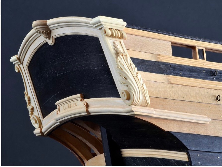

- 2,699 replies
-
- 15
-

-

-
- heller
- soleil royal
- (and 9 more)
-
Yes, same rationale for the kevels. As you approach the upper bulwarks, I encourage you to take a little extra time to fill/level injection mould marks. It’s one of the shortcomings of the kit that it is loaded with tons of these moulding artifacts - not coincidentally, that is probably why the injection-moulded detail is so crisp on this kit.
-
Yes, I glued-in the companionway supporting knees early because I wanted a strong plastic to plastic bond before paint. I also wanted really good alignment, and this was just easier to do off the model. Same with the eye bolts.
-
This is really exciting and great for me, personally. I have been searching for what my transitional project might be, and I love David and Greg's model of this pretty little ship. I know that your kit will be first-rate. It'll be a while before I dive-in, but this is exactly what I was looking for to accelerate my learning curve of POF construction.
-
I appreciate that you can hear me, without getting too ruffled about it. Always, with this kind of thing, I consider whether X, Y, or Z detail is a distraction to the model. In this case, I felt it took focus away from the model, where it should be.
-
I agree with all of the above.
-
The other consideration is that the brightness of the pedestals is at odds with the weathered appearance of the model. One approach might be to cut away the lobes of each knob so that there is a parallel center that runs closer to the keel. Then I might strip away the lacquer and use brass black to give them some patina.
-
If I’m being honest, Michael, I don’t like the brass knobs. They come-off as too heavy for the scale of the model. I’m sorry to be so blunt, but they elicit a pretty visceral reaction for me.
-
That is correct - I cut away the top-most sheer step and replaced it with a 1/2 height caprail that extended the full-length of the third sheer step. Ultimately, I am shortening the length of the poop royal deck a bit (maybe about 1/2”) to avoid this problem that Bill has encountered. Since I’m making all of the decks and bulkheads from scratch, I feel comfortable doing that. All that said, I may slant the poop royal deck so that it follows the sheer of the railing. I won’t really know for sure until I get there.
- 1,508 replies
-
- 2
-
-
- Le Soleil Royal
- Heller
- (and 1 more)
-
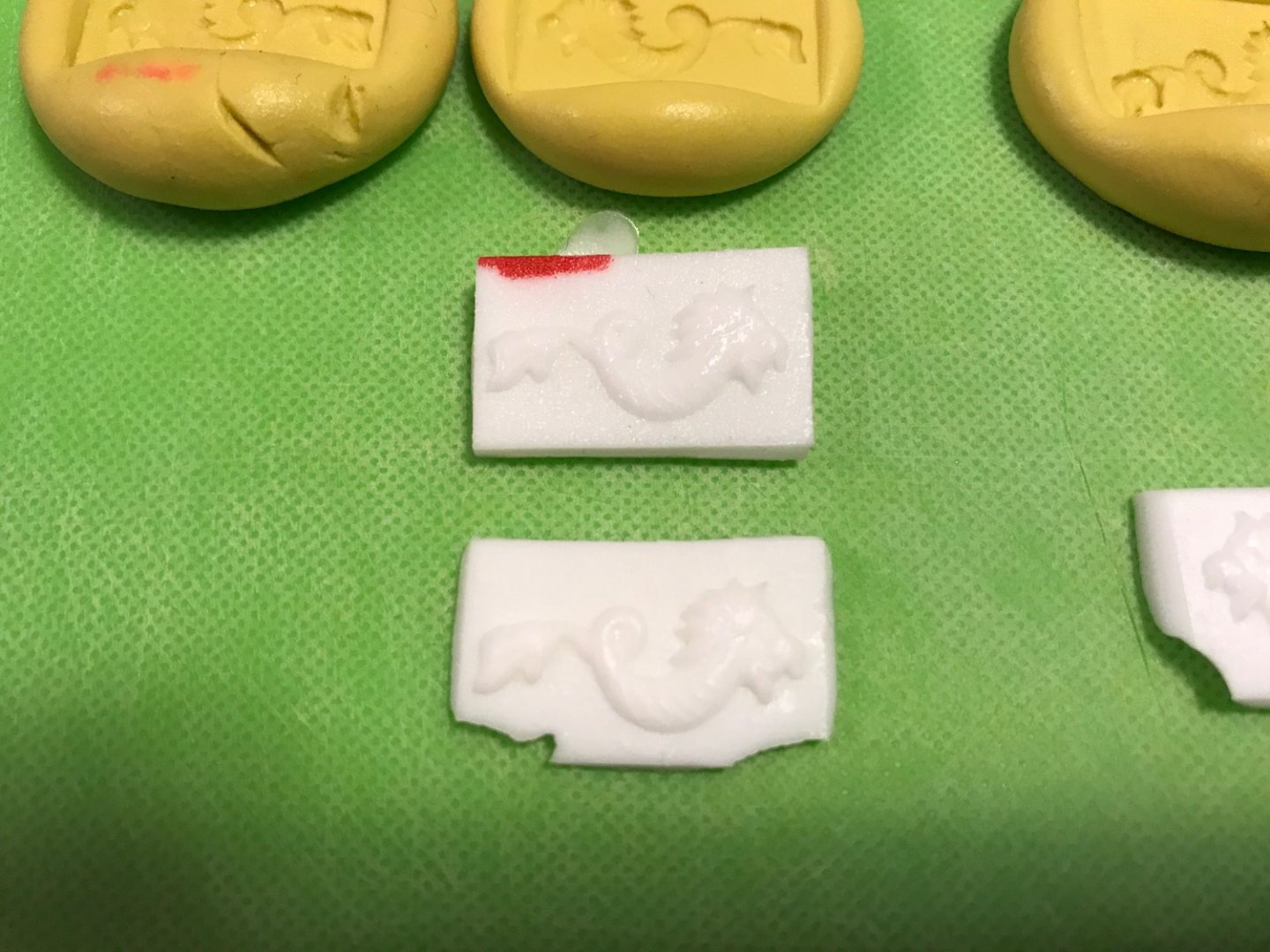
It was the same process as described above; carved a master from styrene, mount to plywood block, make a mould from latex, cast into mould.
-
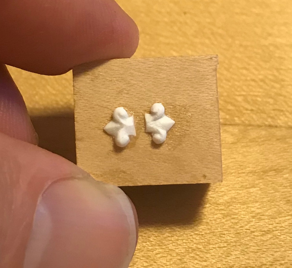
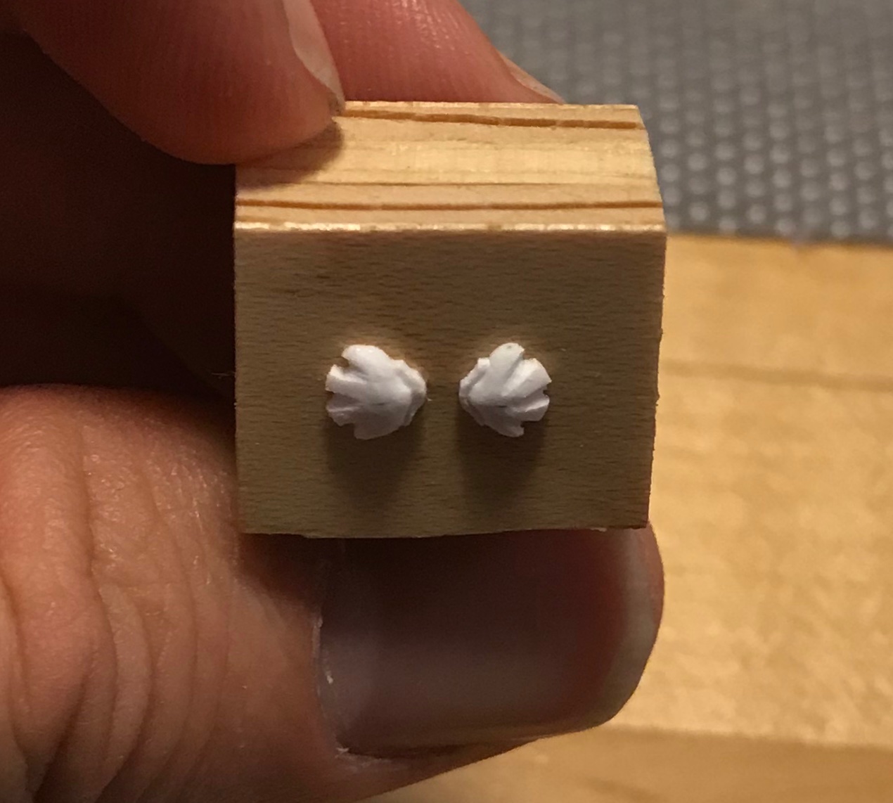
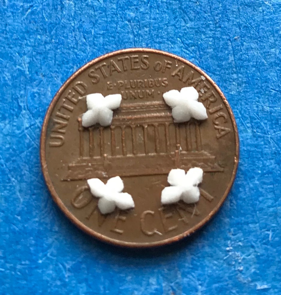
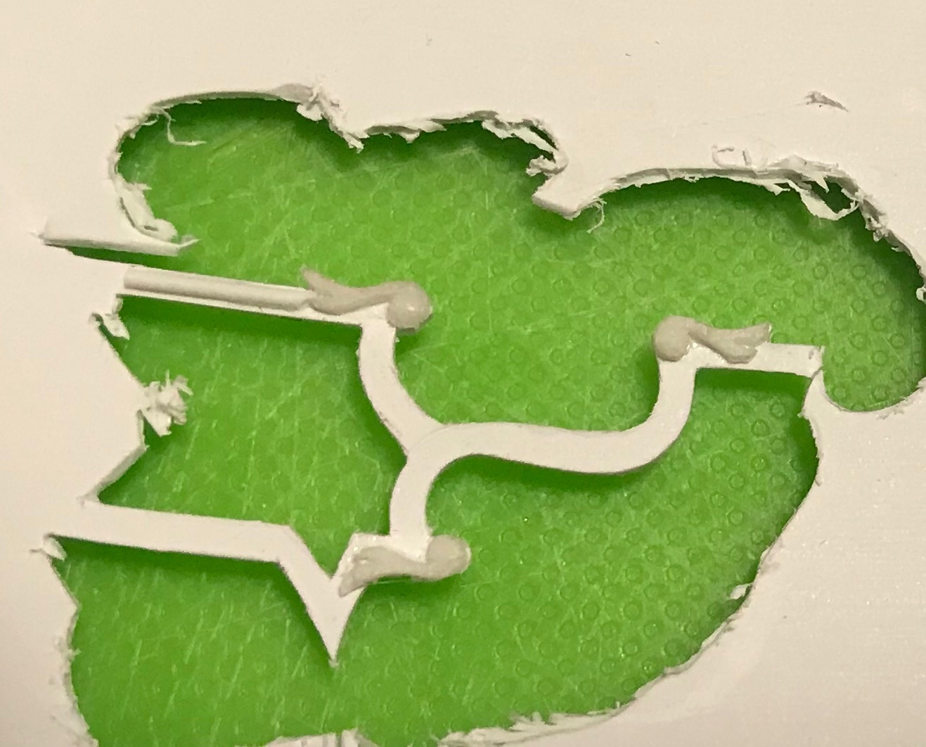
For all of the frieze ornamentation, I carved masters out of styrene and then mounted them to plywood blocks that I could then make casting moulds from with a latex mould medium. The castings themselves are a 2-part resin - Allumilite - that requires a lot if wasting to eliminate the background material, after casting. It was not an efficient process. However, it is the process I knew I could get great results with. I could never quite see bow to model carvings in Sculpy clay the way some so masterfully do. The frieze lattice was laid out on paper, transferred to .015 sheet plastic and ever so carefully cut out: It was a tremendous labor that was worth it, in the end, but I spent the better part of six months working at it - a lot of hours!


-
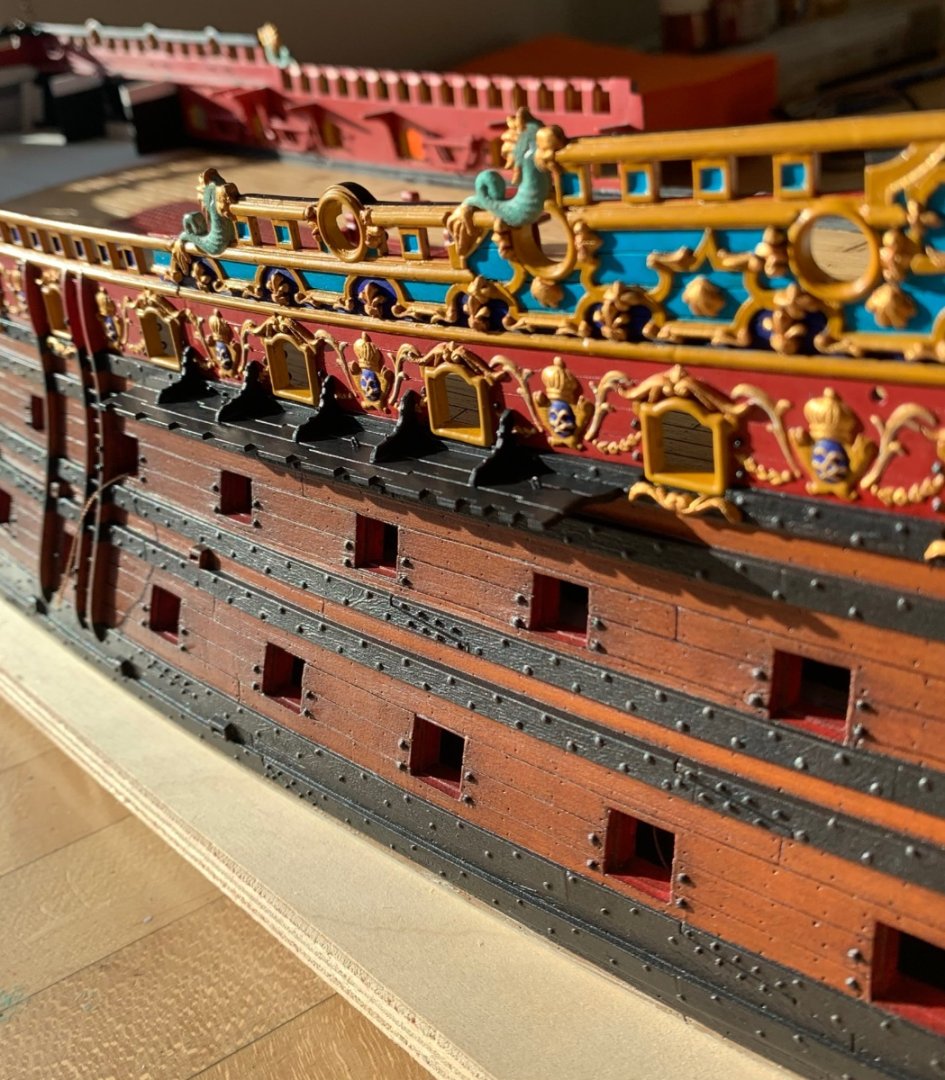
The “vertical white stripes” you are seeing on the exterior of the bulwarks are the continuation of the waist “skids,” or rub-rails that ease the raising or lowering of the ship’s boats past the wales. You can see the skids, here, on the left side of the picture:
- 1,508 replies
-
- 1
-
-
- Le Soleil Royal
- Heller
- (and 1 more)
-
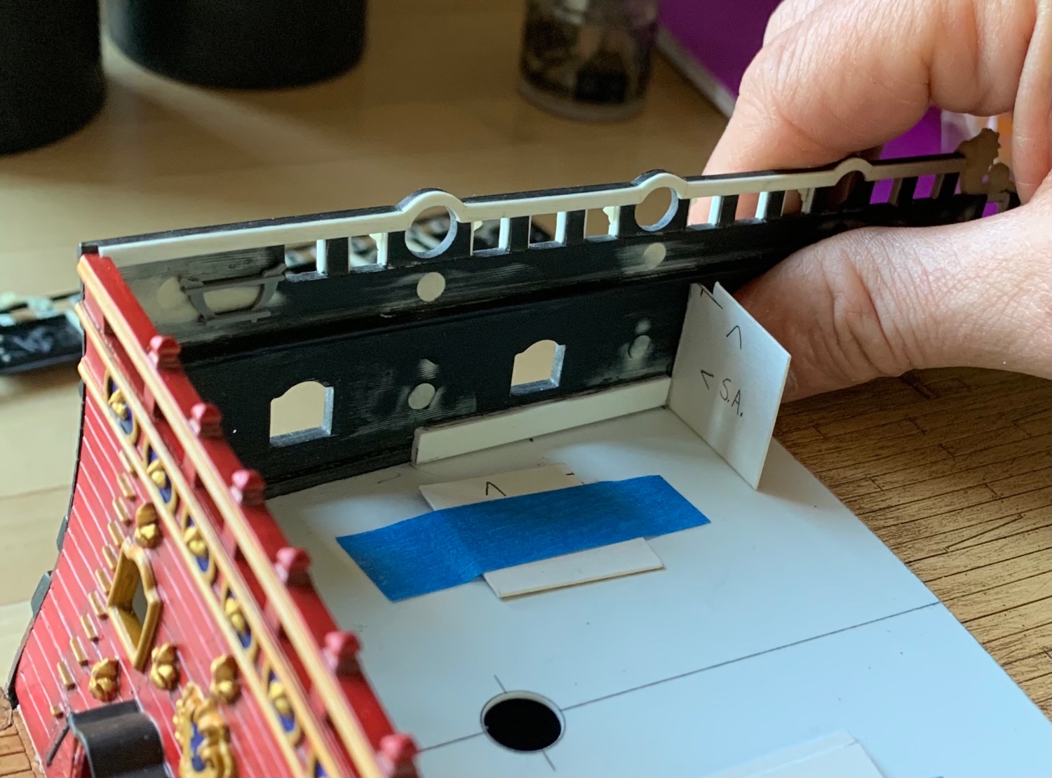
Not to be a total pain in the ***, but the Evergreen strip you are showing next to your caprail is easily twice the thickness you need it to be. Aim for .032 - .028; I’ve run out of what I used, but that’s a good approximate range. What you are seeing on the verticals (interior bulwarks), and vertically/horizontally on the exterior of the bulwarks is my attempt at visual trickery; on the standard Heller kit, the exposed timber heads, that make up the verticals of the railings, are much “taller” than they should be. My decision was to widen them, by adding styrene strip to the sides of the timberheads, but also to create a recessed panel that is visible from the outside of the bulwarks - those are the short horizontal strips. The intended effect is to focus the eye on the much smaller recessed panel, as opposed to the still too tall exposed timberheads. Making them a little wider enhances the effect. In truth, all timberhead railings should be shorter like the one I fabricated for the poop-royal rail: I did the same thing again, on the beakhead bulkhead railing - because it was easy to fill-in and do so: That’s what they should all look like. I’ve made compromises all along the way; adjust this to approximate THAT, while creating THIS to represent what it’s supposed to be. Proof of concept:


-
And, yes, the moulding of the kit has not changed at all from the mid-70’s when it was released. These parts are interchangeable.
-
This middle “narrow” section is what I mean by the waist section. It would be a mistake to add anything here because what it really represents are the exposed timberheads (that make up for the vertical members of all cap-railings), which then have an external sheer-strake nailed to them. As far as the kit is concerned, this isn’t exactly perfect proportionally, but it is correctly modeled as a detail, so I would leave that alone. Personally, I was only concerned with the sheer rails of the forecastle deck, the quarter, poop, and poop-royal decks.
-
That’s a pretty thorough accounting of what’s involved.
-
I agree with Ian on that one. What we’re referring to with Evergreen and the cap rails is to thicken the inside edge of the caprails so that they don’t look so thin. It’s the same idea is thickening the gunport openings with Evergreen. In the picture above, you can see the white Evergreen along the caprail. There it is again on the top bulwark pair. I did not do this in the waist railing, though.

-
Replacing the pins is a great idea. Yeah, I would go ahead and glue the upper bulwark halves together because you will have the beakhead bulkhead and stern plate in place for you to anchor the bulwarks to. If I recall correctly, you do need to install the beakhead and stern plate first. On my current version, I didn’t have a stern plate to anchor to, so I had to create a series of gussets that anchored to the deck and thus gave me the correct tumblehome for the aft bulwarks; this was very tricky, and frankly, a pain. The worst of it, though, was trying to fill/sand/paint the bulwark joint on the model. That was very difficult to do and still end up with a seamless paint touch-up. Lots of hours spent there! Since you can avoid all of that, you absolutely should.
-
Yeah, that isn’t too bad, but with a little patience you can close that gap to zero. The worst pieces are the forward bulwark pieces, which have to flex quite a bit to even get into position.
-
I am going to make a strong recommendation before you begin painting your upper bulwarks: take as much time as necessary to get a good fit of the UB’s to the rabbet just above the main deck. This is THE worst aspect of this build because it is so poorly fitting; SR is no Heller Victory, in this regard. Trust me - you do not want to do all this careful paint and gilding work, only to then have to handle those parts excessively to make them fit. The parts are always going to be under tension because they do not neatly conform to the X/Y curvatures of the hull. Not at all, really. On top of that, the rabbets are not clean, and to get a good bond, you’ll want to fair these with a small, hard block to which you double-stick some coarse sand-paper. Doing these things will REDUCE the amount of tricky putty work you must do, afterwards, although it will not completely eliminate it.
- 1,508 replies
-
- 2
-
-
- Le Soleil Royal
- Heller
- (and 1 more)
-
Main deck looks great, Bill! When I say that I cannibalized the kit quarter galleries, what I mean is that I pulled three small ornaments out of them to re-incorporate into the new quarters. My build-log is absurdly long, but somewhere in there details the full process of drawing the QGs, and fabricating them from wood and plastic.