


Hubac's Historian
-
Posts
3,220 -
Joined
-
Last visited
Content Type
Profiles
Forums
Gallery
Events
Posts posted by Hubac's Historian
-
-
-
Well, you have to admit that the number of times people ask to see videos of her sculpting process is a little out of control. Firstly, she always incorporates them into the log, so they can be found there, if curious minds look a little. Then, there’s her presence on YouTube where quite a number of those videos reside in one place.
I have to say that as many times as I’ve watched these videos - despite how easy she makes it seem - I had such a time replicating anything passable. I gave up, for the time being.
- popeye the sailor, mtaylor, TOM G and 2 others
-
 5
5
-
Hi Frank,
The scale of the kit guns does not bother me, and in fact, I find them to be quite nicely proportioned castings. I like them as they are. Your build had me browsing Heller Reale builds and the artillery on that kit is also quite stout.
Some have posited the opinion that the Van de Veldes, for example, may have exaggerated the scale of artillery on their ship portraits, but I do not believe this is so.
The Galleys were, in fact, intended to be fighting ships, and not merely transports for the king.
-
You know, it is so great to see her in natural light, where all of the extra detailing work you have done really pops, EJ. You really have done an incredible job of transforming this kit into something so much better than the sum of its parts.
I really love your top work, and as I’ve said before - the shrouds and ratlines are top-notch!
- md1400cs, EJ_L, popeye the sailor and 2 others
-
5
-
Hi Clark,
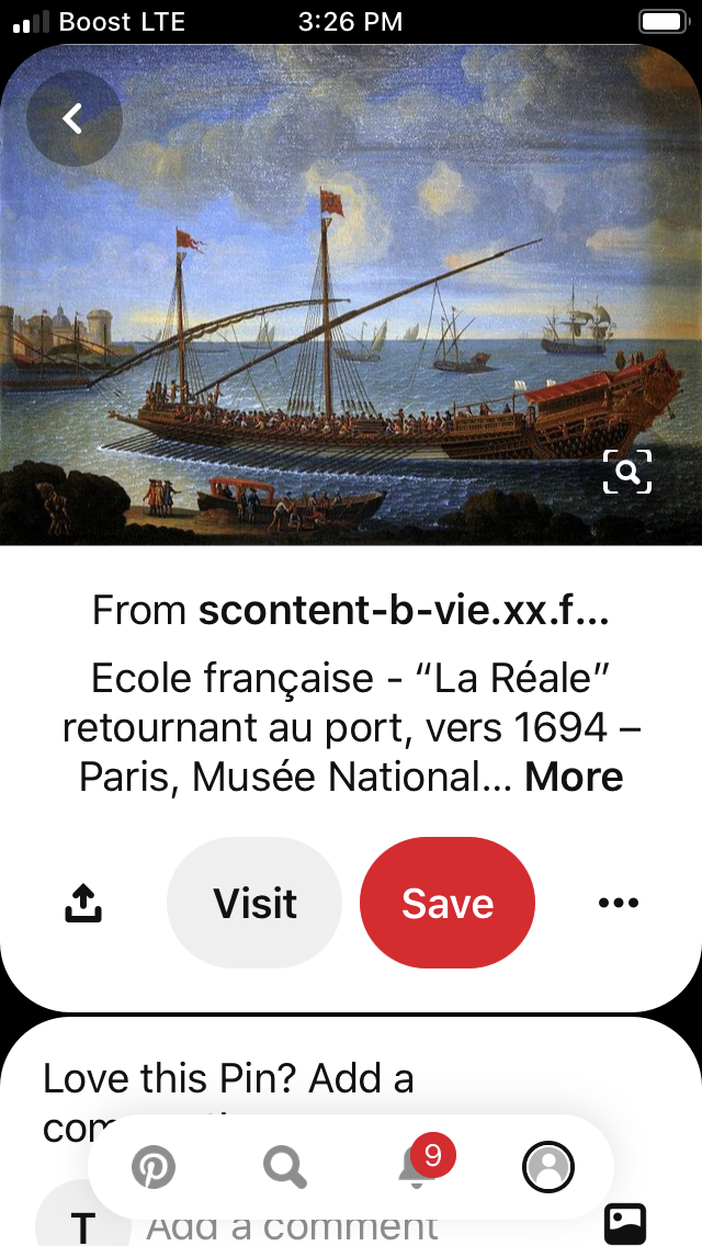
This image came from my Pinterest page, French Vaisseaux.
When I clicked the embedded link, it just took me to a blank page. All I have for you is the partial web address you see in the screen capture, above.
However, if you visit my Pinterest page, you will find nearly 900 images of French ships from the 17th and 18th century; portraits, models, etc. As far as I know, it is the most extensive database of related imagery on the web.
Check it out - there’s other Galley stuff in there, as well.
-
Hey MD - thank you for the thought and for your kind words. I know that I should probably space out my postings to reflect more generous progress, but I am very glad that this interests you, nonetheless.
What I ended up buying for the window stock was a clear poly carbonate, maybe 3/64”, but not quite a 1/16”. I’d say for sure, but I don’t want to wake my wife, rummaging around for it. Dan Pariser once told me about a marriage that went south over a very long, long build.
Anyway, when you pull away the plastic protective film, it’s just a perfect mirror glass finish. How, exactly, would the treatment you’re proposing, affect the surface sheen? I am always open to suggestion, here.
-
-
-
The last line:
Along the railing at the stern are two figures with wings recognizable. Next, an angelic figure is visible, which seems to be after the rudder (T). Furthermore -
I copied a picture of the text into my Google Translate App. This is what it came up with:
La Réale - Royal Palaces and Galley Vows by Florian Vitz The viewer sees a detailed drawing of a ship with PI. | I is numbered. Subtitled is the drawing with the words "Marine, Dessein d'une Galere à la Rame nommée la Réale" .² Based on the accompanying text from the maritime area of the Encyclopédie and the explanation at the bottom left edge of the picture, the observer learns that the drawing of M Belin was made.3 Jacques-Nicolas Belin (1703-1772) was a well-known nautical cartographer, 4 who played a major role in the creation of maritime articles such as the corresponding encyclopédie (planches) prints.5 However, the present Image panel around a copy of Belin's original drawing. Consequently, the illustrator is the Louis-Jacques Goussier (1722-1799) image-plate. He was a mathematician, draftsman and Diderot's mechanical arts assistant.7 The right side (starboard) of the ship can be seen. At the stern of the ship (A), the observer sees some elaborate engravings that can be recognized on the outside. Along the railing at the stern are two figures with wings recognizable. Next is one
-
-
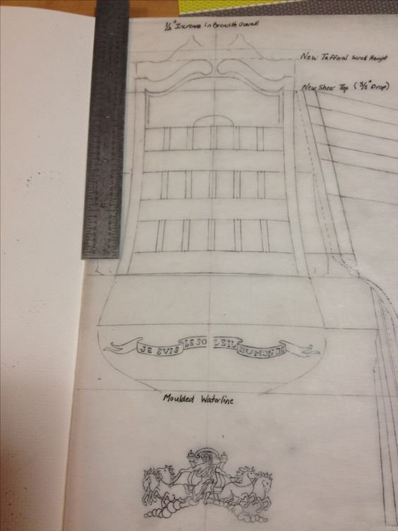
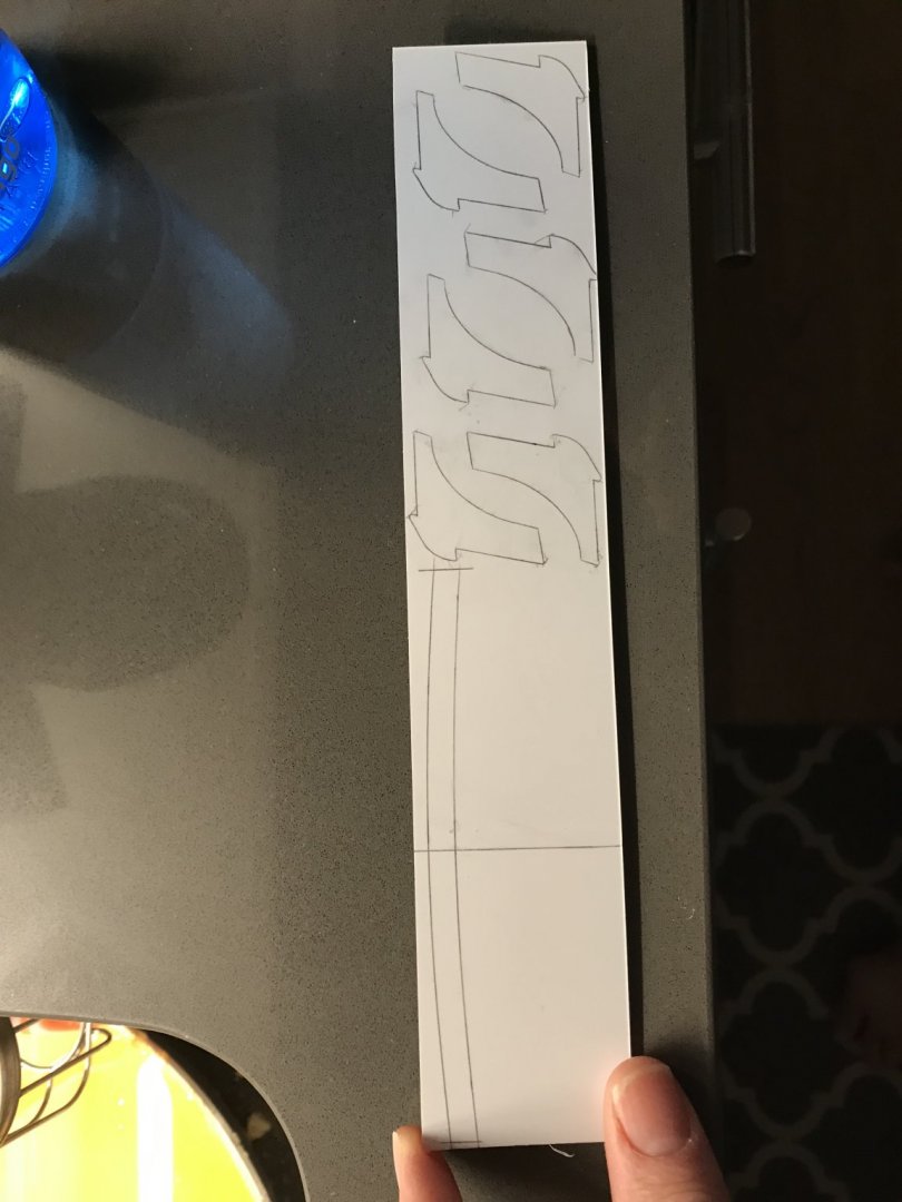
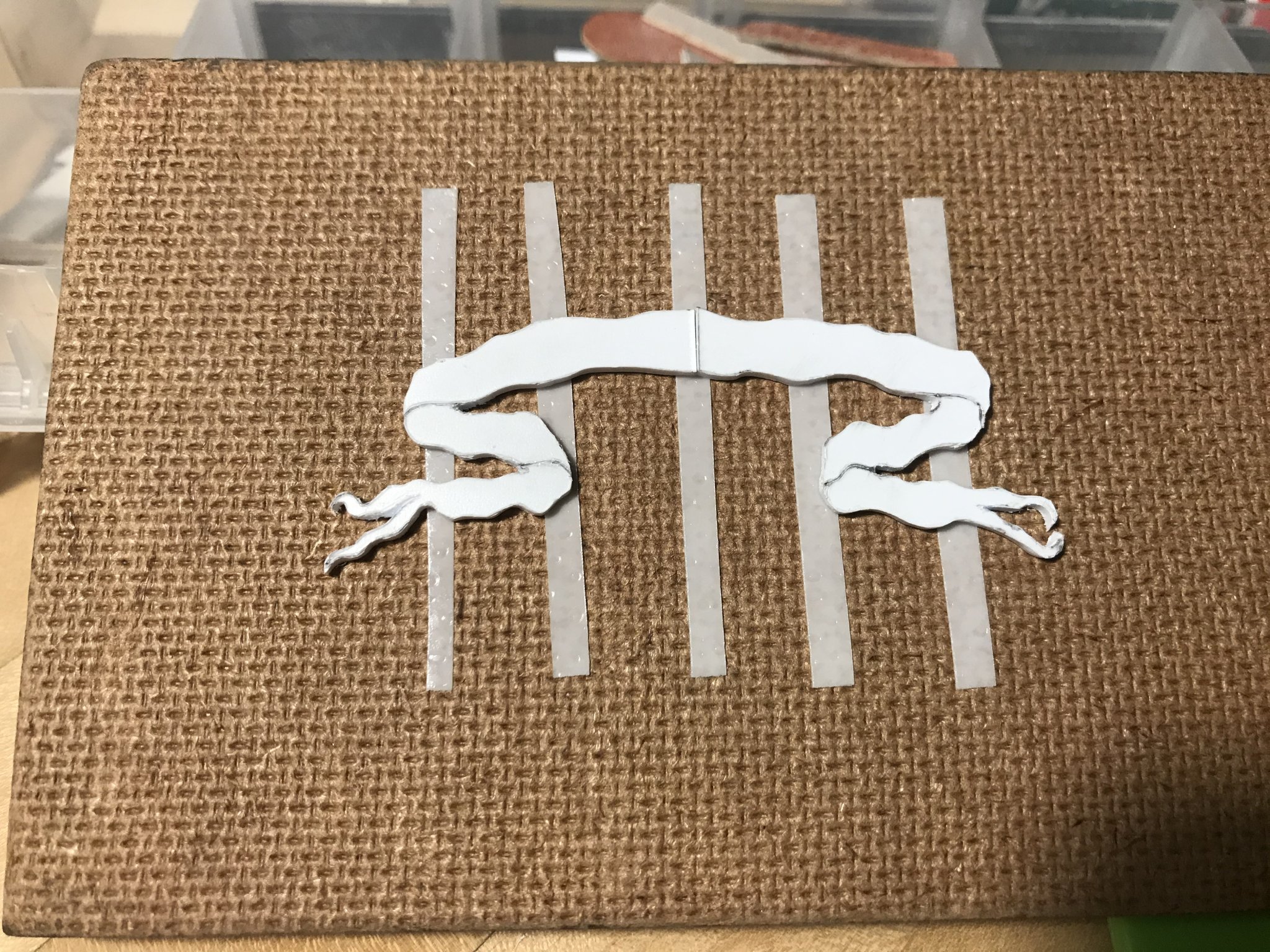
So, among other small projects - the bulkheads and the transom wale - I’ve made a start of the scrolling banner that I will carve for the area beneath the transom wale, and between the through-bolting of the transom knees.
The scrolling banner that I initially drew was always a sort of placeholder, but not one I really liked. The motto shown, here, was my own bit of authorial license, before Dan brought something much better to my attention. It’s a little too cartoonish for the French Baroque period:
Eventually Drazen Caric got around to an amazing step-by-step of the carving for the name banner on his incredible Provincien. The sense of movement that he conveys is much more the impression that I am after. If anyone is not familiar with his impeccable work, you can find it here. Posts concerning the name banner begin with post # 304:
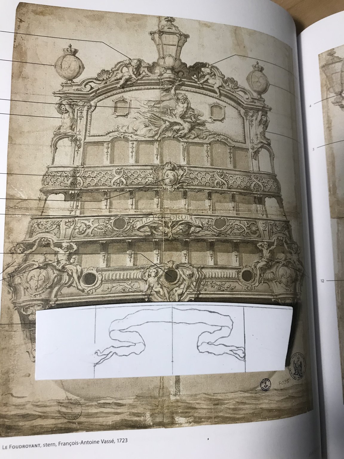
The other guiding inspiration is the name banner for the Foudroyant of 1723, which I could finally see in all of its splendor in Floating Baroque:
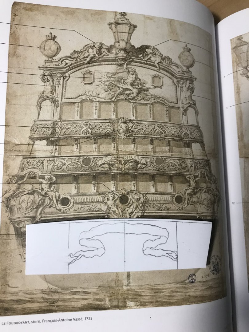
What I have patterned, here, is not an exact drawing, but it captures the overall shape and sense of movement that I think will look very good in the available space. Carving the three-dimensional undulations of the ribbon will be a fun little project. Bear in mind that there will be a 1/4” separation between the two halves, for the sternpost.
I’m thinking that I will probably draw the letters for the latin motto, NEC PLURIBUS IMPAR, onto parchment. I can then stiffen them with dilute varnish and cut them out, individually, to be affixed to the banner.
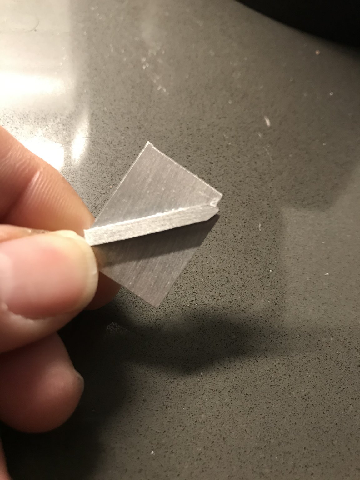
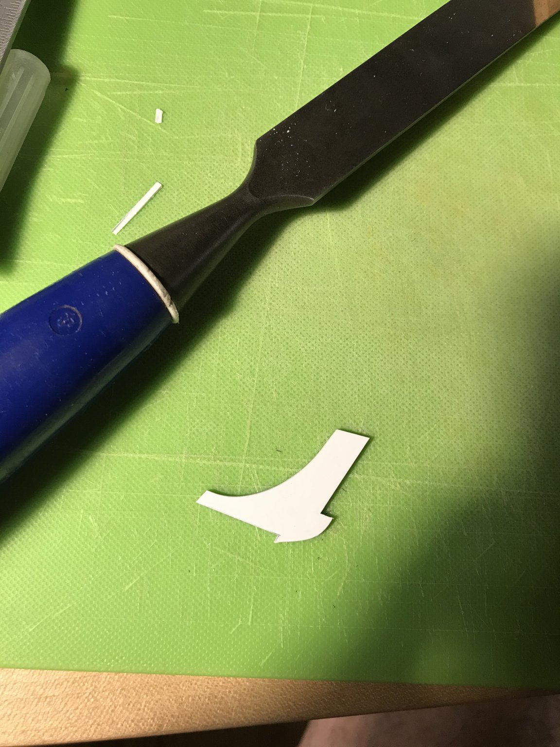
My other experiment was making a moulding scraper. My first problem is that I want to cut very small coves into the edges of my transom wale - not much larger than 1/32”. To my mind, at this scale, it is very difficult to shape that small cutting nub into a hardened steel scraper, while maintaining sharp corners. I have little idea, really, how to do that convincingly.
My first thought was that I’m scraping styrene, so maybe the scrapers don’t need to be steel. They also don’t have to last forever. Maybe, I thought, I could make them from aluminum scraps, which I have in abundance.
My second thought was that maybe the cutting nub didn’t have to be shaped into the scraper body; maybe it could be an independent part that I cyano’d in place.
So, this is what I came up with:
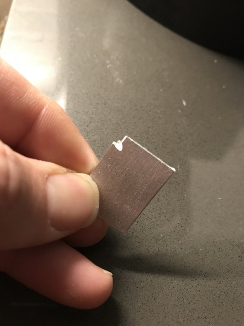
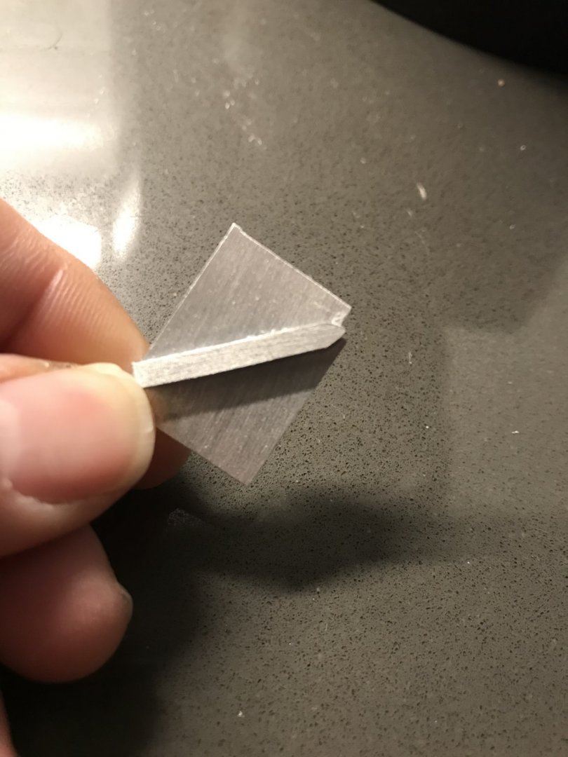
I filed a chip relief into the corner, but I did not file all the way to the very back face if the scraper. I left about a light 1/64”, and I think that even that small lip is enough to clog the action of the scraper.
It works pretty well for a few passes, and then not at all until you really clean it out.
Today, I’ll release the cuter, file back that lip, and introduce a very slight burr to the cutting edge, and we’ll see what that does.
If that doesn’t work, I’ll have to figure out how to make the one-piece, steel scrapers.
-
-
I wasn’t expecting to be in the city shop, these few days, but whenever the opportunity arises - I like to do whatever tedious pattern work that needs to get done. Access to a band saw, disc and spindle sanders, simplifies the making of the series of bulkheads that will form the counter/false balcony.
Yesterday, in the shop, I made the first bulkhead that would ultimately serve as the pattern for the others.

First, though, it had to be proof-tested on the model to ensure that it mirrored the already established camber and round-up.
I used my quarter gallery drawing as the basis for my bulkhead profile. What I discovered, though, was that there are two important notches or step-backs that needed to be cut into the bulkhead; my pattern was based on the exterior, or extreme outline, but I needed to make an allowance for the thickness of the planking.
My first bulkhead did not, initially have a notch along the bottom. Using a batten I found that it exaggerated the camber - which would then mess up the whole run of windows I just drew so carefully.
And then, after I cut back the vertical portion that supports the windows, as well as trimming back the counter profile, everything lined up properly, as it should.
Here is today’s workload: cut out my bulkheads, and cut out the basis for what will be a stacked moulding for the transom wale. The transom wale seems to be a hair on the heavy side, but I can fine-tune that, once I can offer it up to the model.
Also, now that I have a useable pattern, I could better see how the counter ornaments were going to resolve themselves. It was really handy to have the bandsaw to waste out the middle (the head and crown) of my spare counter ornament.
Now, certainly, there is too much space between the head and the acanthus scrolls. What I will do is a bit of visual trickery; I’m going to let the base of the scrolls into the last of the upper transom planking, so that it glues to the transverse bulkhead beneath. The front edge of the acanthus base will also be let into and come out flush with the facia plank (not yet installed) that covers the edge of the transverse bulkhead. Doing all of this will cut that gap in half. A little gap is okay for me.This letting into the planking is technically wrong, but if it all works out as well as I can see it in my imagination, then the wrongness won’t interfere with the perception of its rightness. As with a number of other aspects of this build - perception of reality is more important than strict reality of construction. You have to fudge things a little to make them work.
- md1400cs, popeye2sea, mtaylor and 6 others
-
9
-
-
I’ve been going back and forth over whether to modify the appearance of my rudder opening. When I framed the stern, I wasn’t thinking about the reality of how the stern post would end just above the framing of the ports, so that the tiller could pass over it, and into the hull.
I was primarily concerned with strength and tying my transverse round-up bulkheads into the sternpost. It certainly isn’t worth the extra effort, to me, to cut down the stern post, so that I can model the entry of the tiller into the hull.
While I agree with Marc and Dan about what the opening probably should look like, at least there is some scholarly thought to support what I chose to represent, at this later time in 1689.
Here is what Lemineur shows for the entry of the St. Philippe’s (1693) rudder head and tiller:

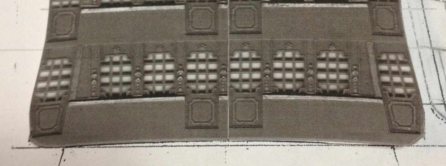
As I say, I will take this learning experience into the next model.Here is my finished lower window drawing:
I think it is definitely an improvement over the Heller layout:
The drawing of the thing is usually harder than the making of the thing.
I’m finishing up with the last of the gun carriages. Following that, I’ll make up the transom wale and my motto banner. Then, I’ll get busy making this window tier.
- popeye2sea, md1400cs, hexnut and 6 others
-
9
-
Hello, Marc! Thank you for the kind words.
I am without doubt that you are correct in this detail. I keep a large cache of Berain drawings on my Pinterest page and they all show the rectangular opening, as do these very fine Puget drawings.
Besides these drawings, though, I had no written reference to their shape, and so I ultimately modeled them after what I saw on Olivier Gatine’s model of La Belle, as well as Tusset’s model of the St. Philippe. In all likelihood, I will probably not feel sufficiently motivated to change this on this model. I will definitely, however, incorporate this into my conjectural model of SR, 1670.
That is, by the way, the best and most clear reproduction I have seen of this port-quarter portrait of Le Dauphin Royal. Thank you for that! I’ll be adding it to my image files.
There is a question I’d like to pose to you, Marc. As I am now figuring out my plan of attack for the stern lights, and the construction of the quarter galleries, I am wondering whether all of the lights in the quarter galleries, at this later time in the 17th C, would have been false lights, with lone exception, perhaps, being the Admiral’s quarters on the quarter deck level?
If that is so, I would back-paint my false lights in a stylized way to represent glass.
-
I hope that everyone enjoyed their Thanksgiving. We certainly did.
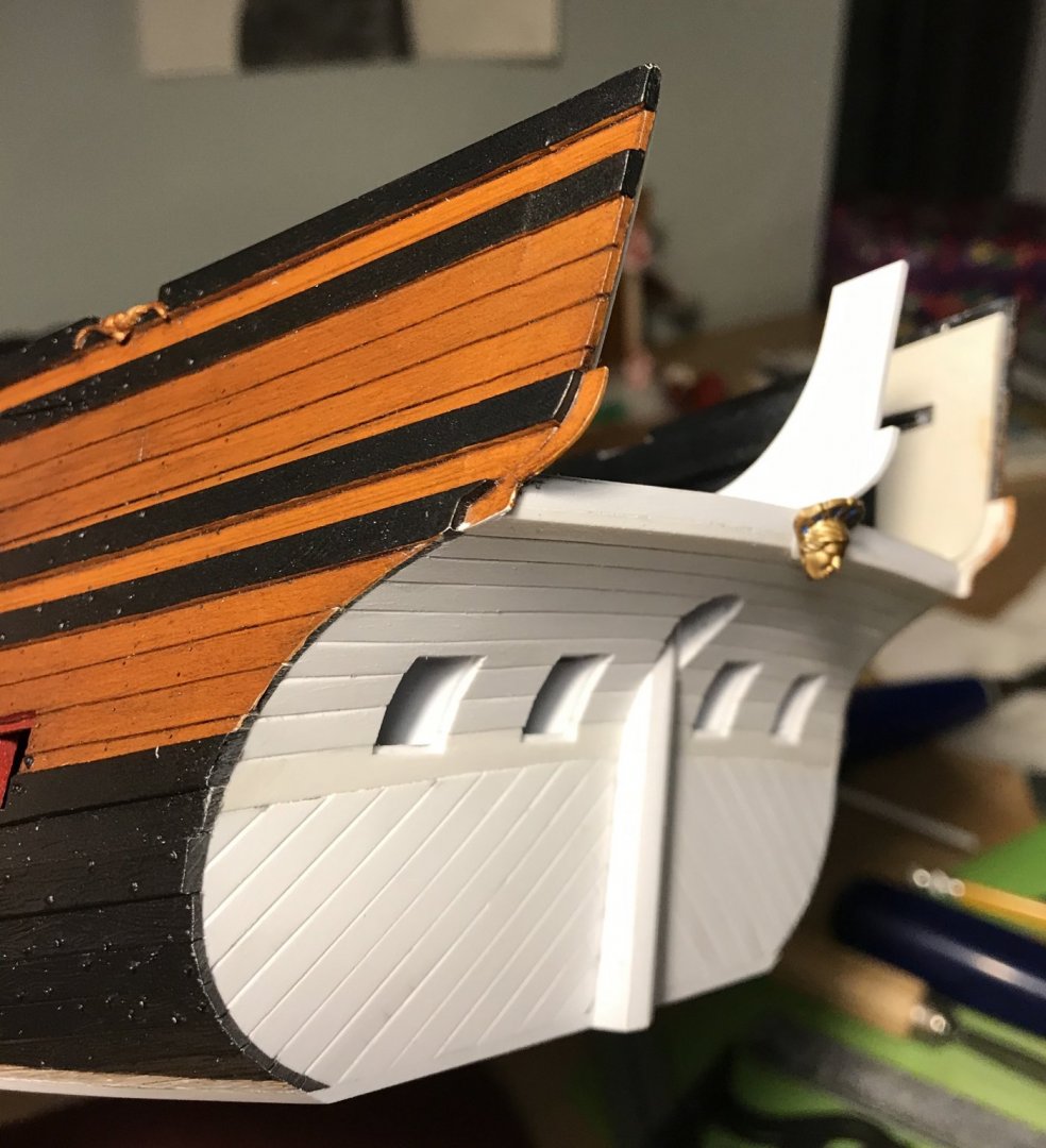
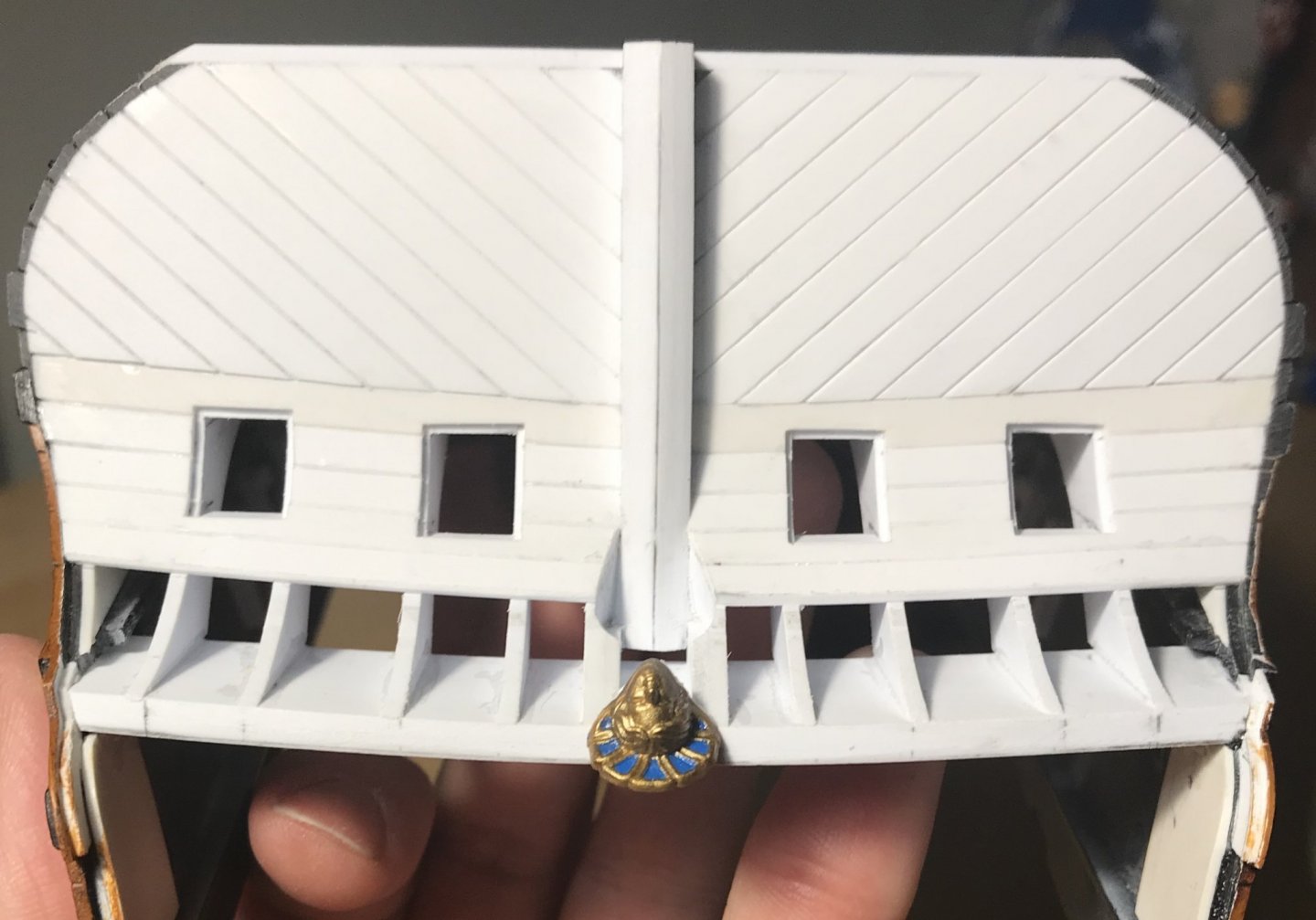
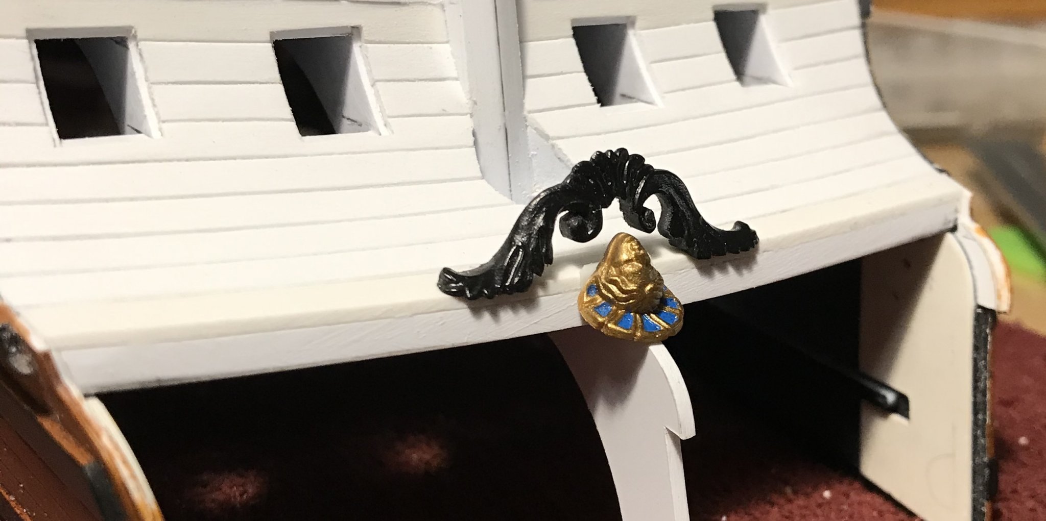
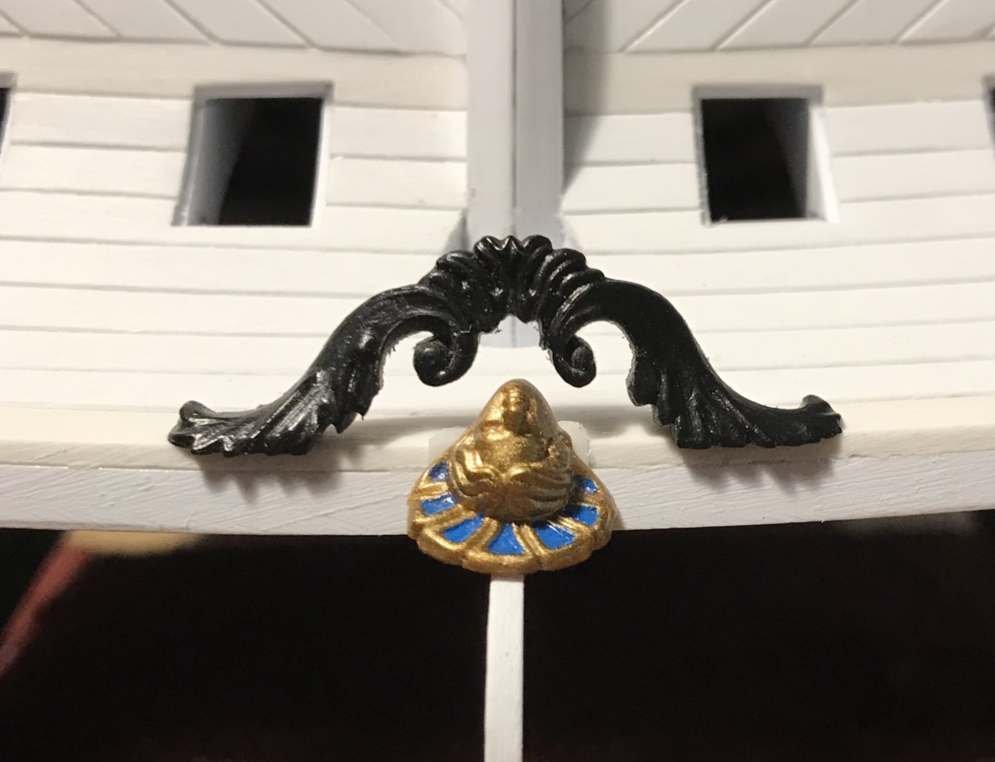
My transom planking continues, and at this point, I am planking across the opening for the rudder head. Before completing the last few strakes, leading into the stern counter, I wanted to pause and see whether I could modify one of the kit’s stock ornaments, in an attempt to present a more faithful representation of Berain’s stern.
What I am focused on, here, is the pendant ornament that drops from the lower false gallery and conceals the rudder head. For all practical purposes, I suppose that this ornament’s intended purpose was to limit the intake of water, through the rudder head opening, in a following sea. I’m not sure whether that is the truth, but it’s a theory, anyway.
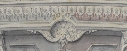
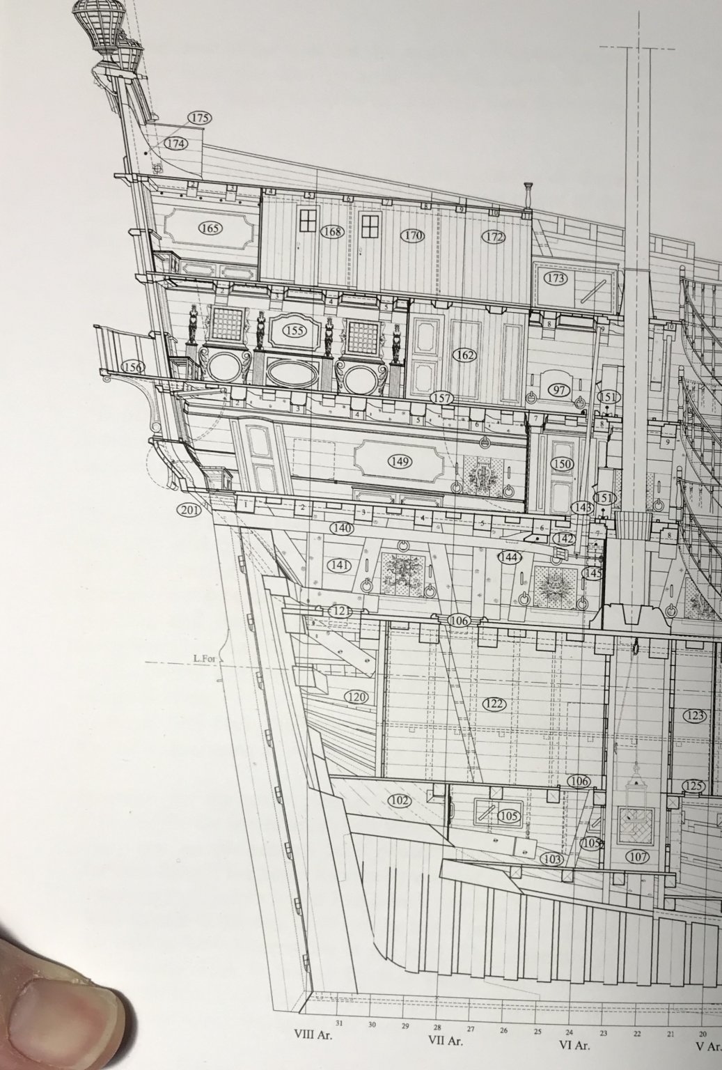
What is interesting about Berain’s drawing is the way in which the Palladian shell backdrop recesses, up into the lower false balcony.The stock Heller ornament is intended to mount beneath a walkable lower stern balcony, as seen here, on Tanneron’s model.
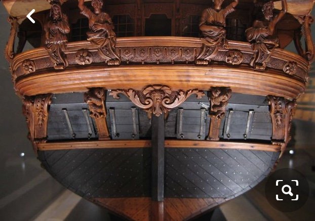
Heller reproduces this detail quite faithfully. It’s nicely done, and would be difficult to carve from scratch, in a way that suits my purposes. I do have two of these ornaments, though.By separating the Louis head and its shell backdrop from the acanthus leaf cheeks, I should be able to set the head so that the counter planking of the false stern balcony abuts it, flush all around. I would then remove the head and shell from my spare ornament and mount the acanthus cheeks just behind the head, once I’ve completed the counter planking up behind the head.
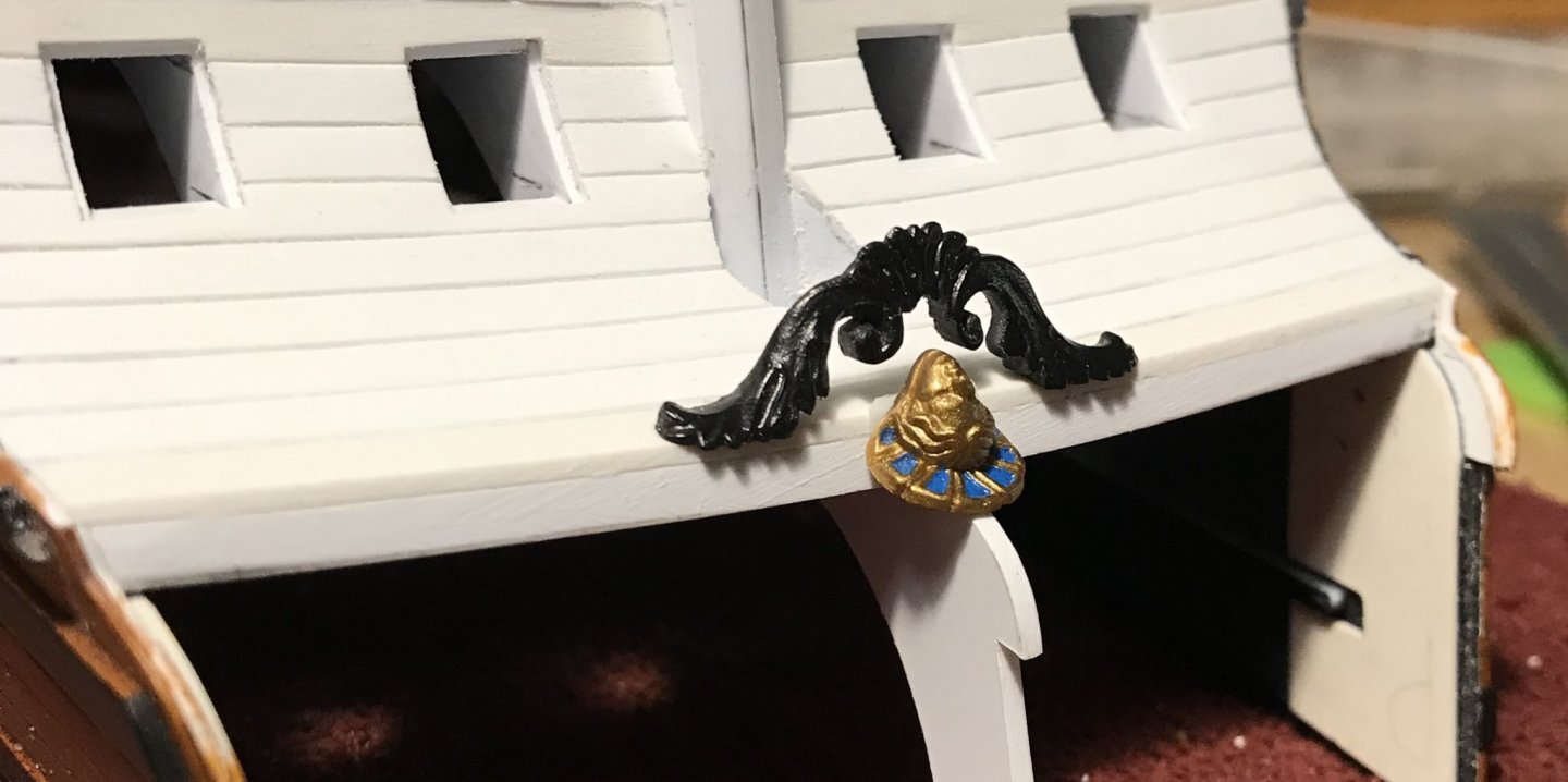
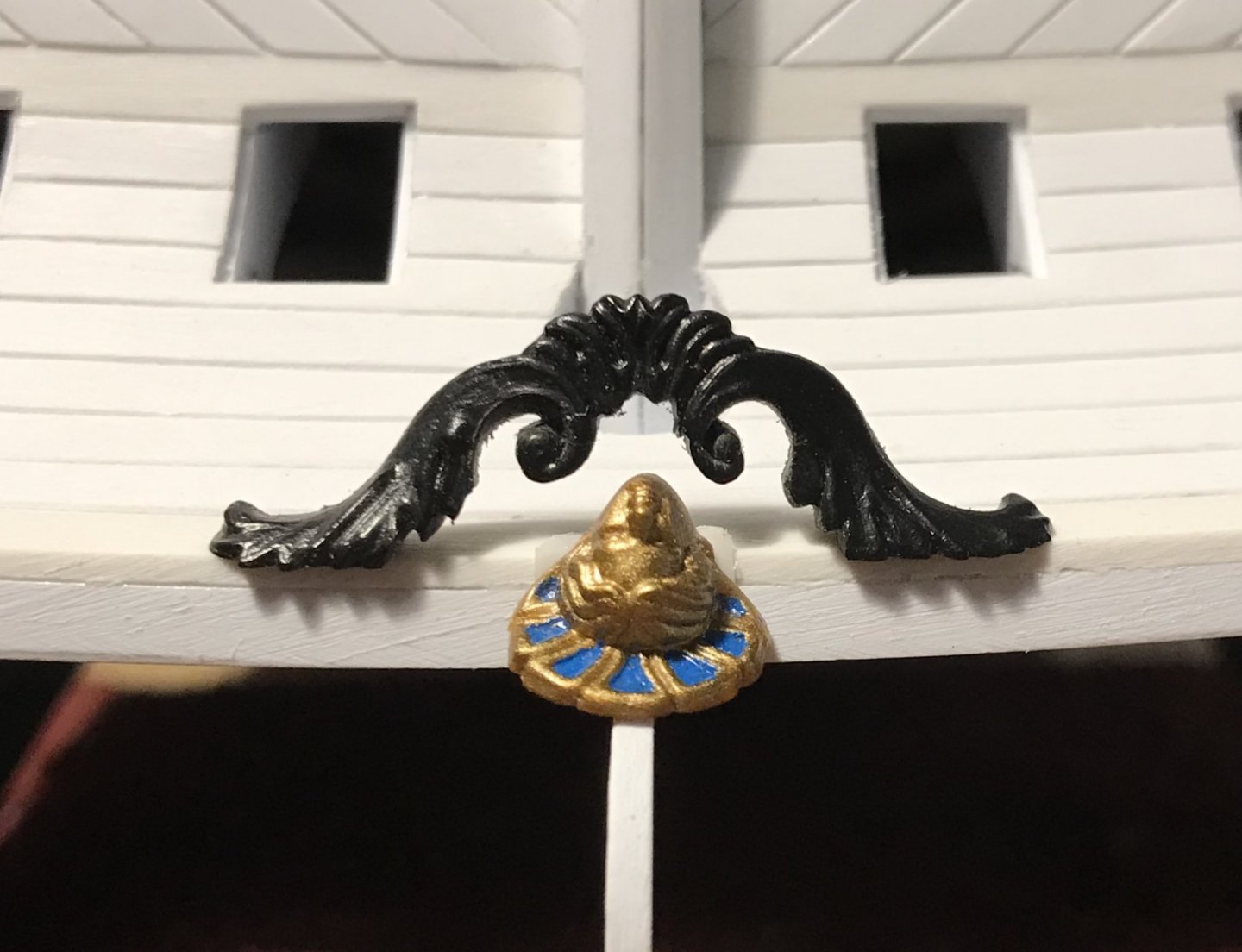
This is a difficult thing to describe, but hopefully the following few pics will make it clearer where I’m headed with this.
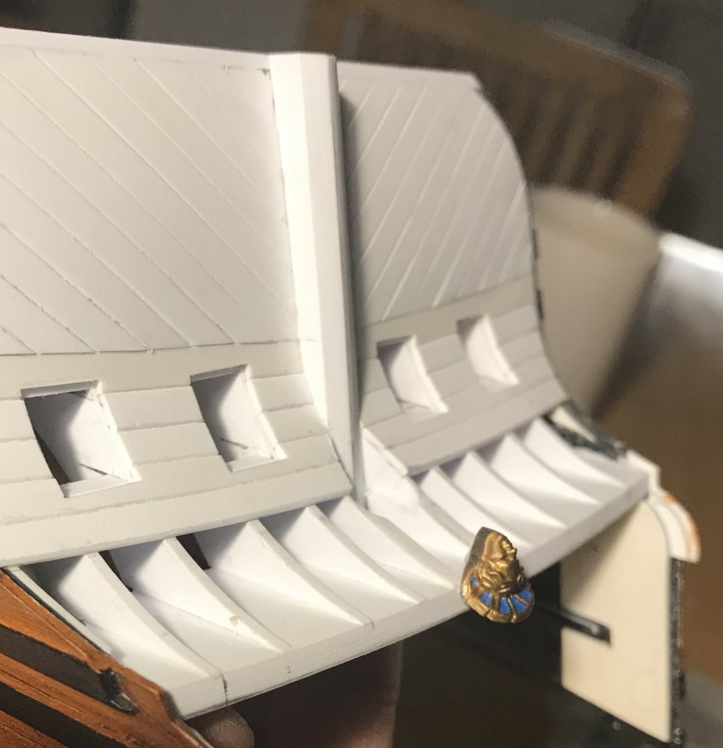
The head isn’t glued in, just yet. I’m not sure whether the new angle that I’ve filed into the back of this piece, accurately follows the run of the counter planking. That will become clearer when I make the bulkheads. This new angle that I’ve ground into the back will tip the shell background and Louis’s cherubic face up into the visible portion of the counter. I’m still not entirely sure this will work, but it’s worth the experiment.
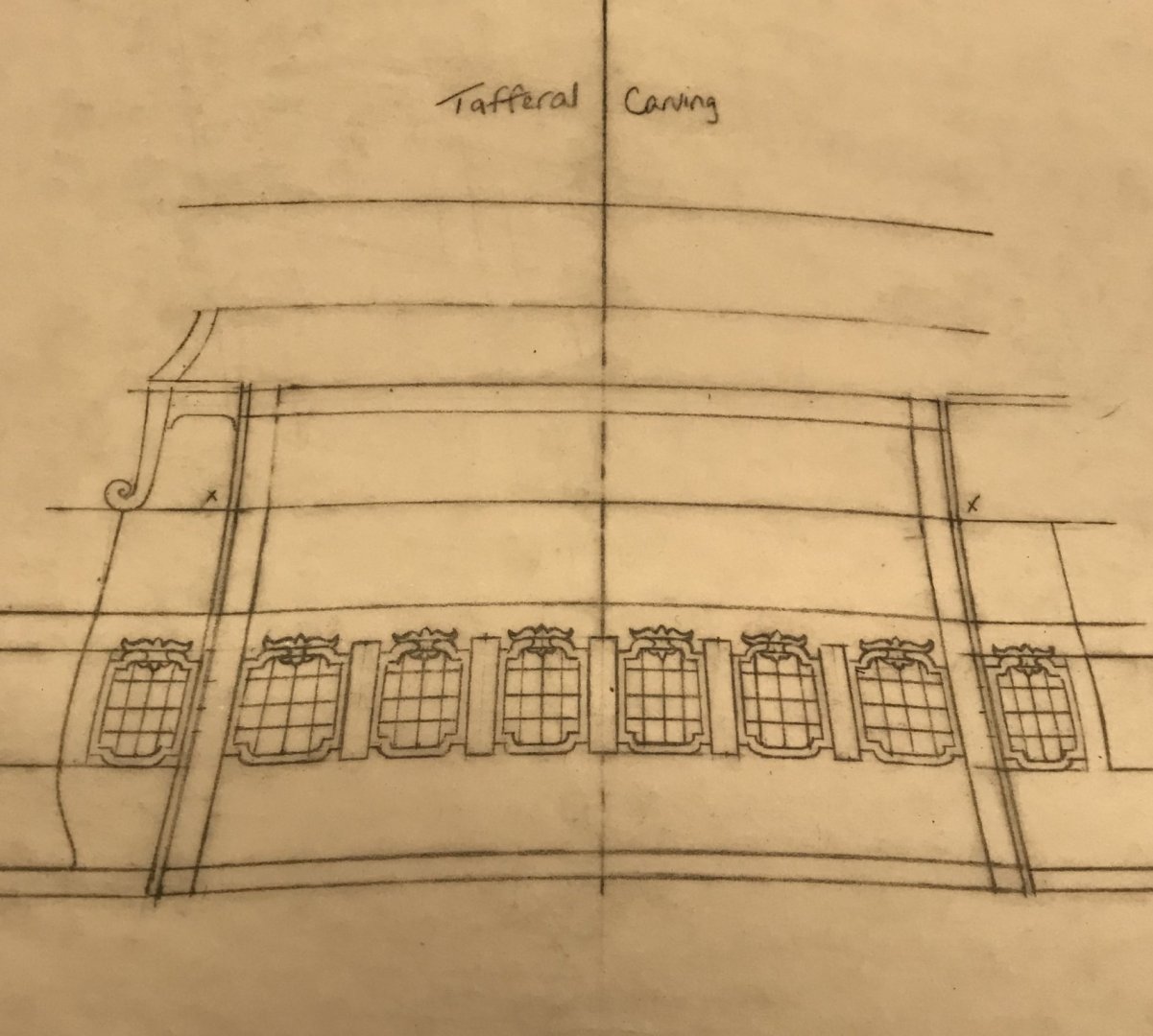
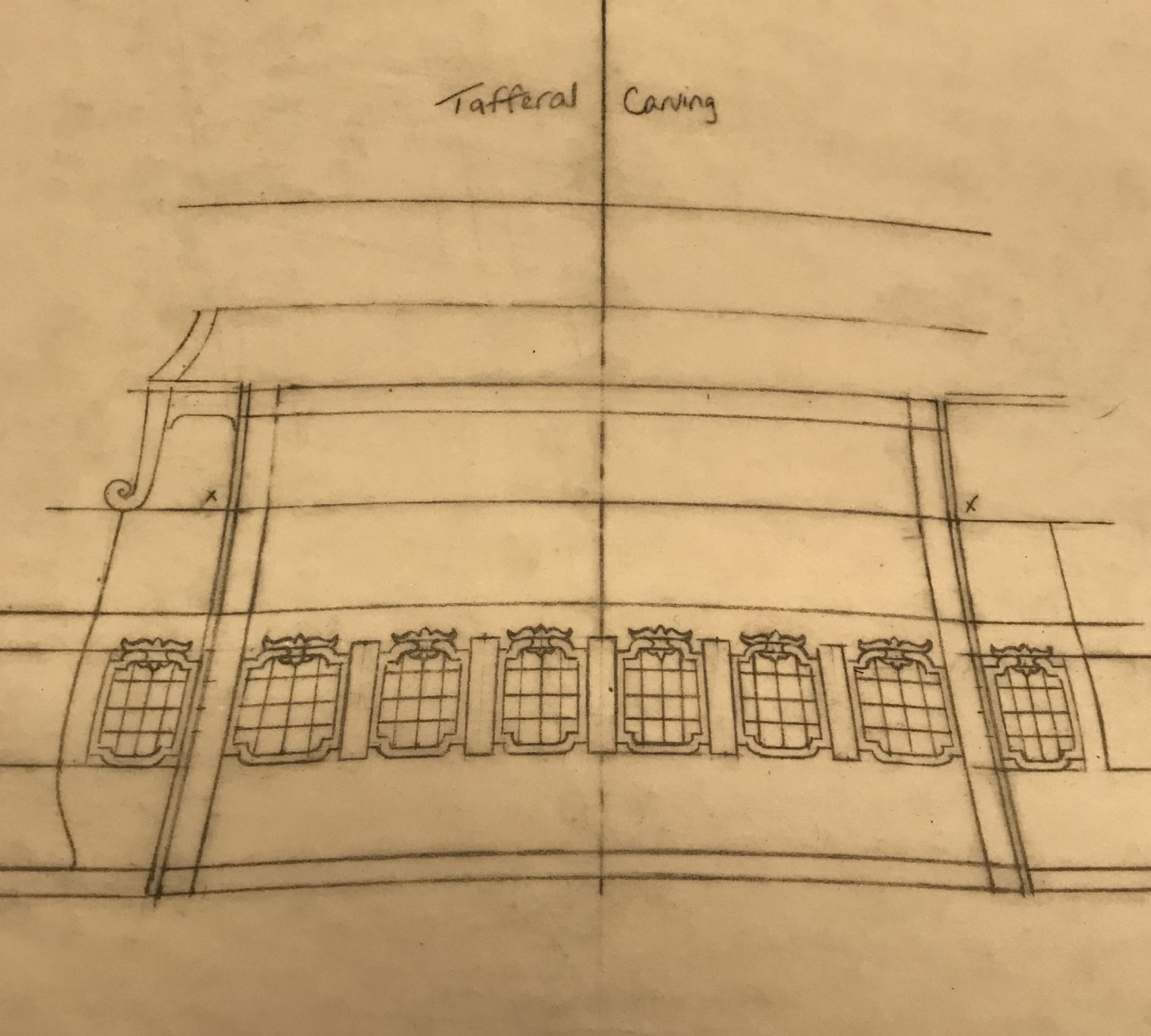
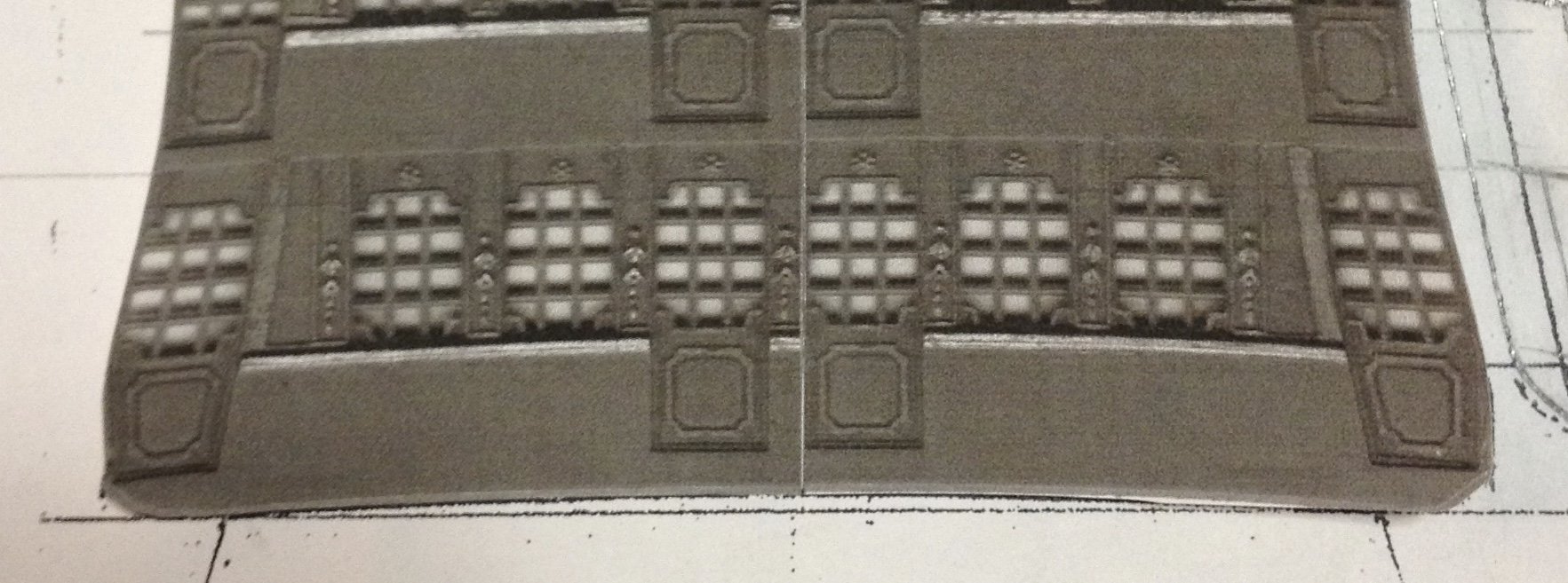
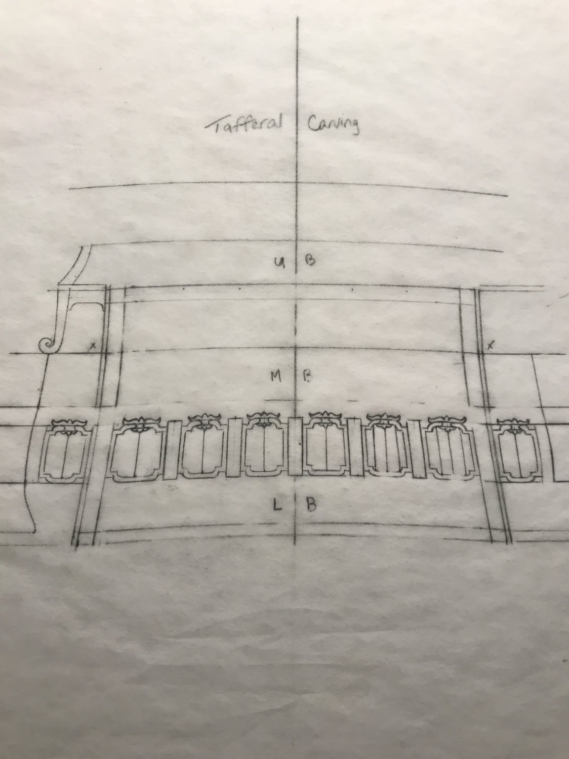
This is where the stern window drawing is at.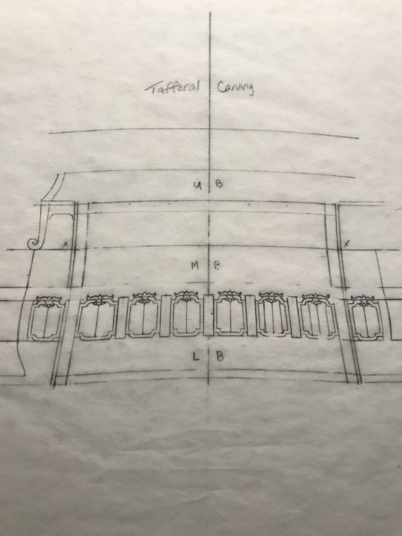
It was a lot of re-drawing to get these cartouche ornaments equally scaled, but overall I like the size and shape of the windows. No matter what, they are an improvement over the stock kit windows.
As ever, thank you all for your interest, your likes and your comments.
- GrandpaPhil, mtaylor, EJ_L and 10 others
-
13
-
As always - great work Frank, and Happy Thanksgiving to all.
I think that loading cannon balls from the front may be the key; there would be no need for haul-out tackles in that scenario. One would only need the haul-in tackles after firing.
As I know really nothing about these Galley ships, I wonder whether they are equipped with a hatchway on this short beakhead deck, through which cannon balls and cartridges might be passed.
-
Yes, I agree that that is an interesting problem. Presumably, the name would be in white, but there are a lot of relatively fine white lines in the frieze. I think the finer the lettering, the better, but I suppose it would really depend upon where the individual letters fall in the frieze. Also, maybe a light but complementary yellow ocher would give enough contrast without overpowering the frieze.
I guess it comes down to something you have touched upon in this log; is it better to be wholly accurate, including every detail, or to leave some detail out, in the interest of cleaner aesthetics?
That’s a tough one!
-
All good and well. Thanks for the insight.
-
On a separate note - I recently asked another noteworthy modeler on this site about the historic precedent for false windows in the quarter galleries, themselves. His particular specialty was also the 18th Century, and so, he wasn’t so sure about that tendency for the 17th century.
I am wondering whether you have some insight into how far back the practice of faking quarter gallery windows goes.
-
Hi Chuck - this is all fascinating to me. Your quarter gallery tutorial could not come at a better time!
The frieze is really interesting. I’m assuming that it’s printed through some process or other. What I wonder at is that - even with laser-cut parts and a very incisive group build-log, which accounts very nicely for variable results - there are going to be variable results. So, I wonder at how one maps out something with a specific artistic framing - like a frieze - so that it can accommodate a multiplicity of outcomes.All I can say is - this is incredible! I’m not asking you to tell me your secrets, but I just wonder at the engineering of the thing. The results are superb!
-
You’re as nimble on the computer as any GEN-Zer I’ve ever seen. That is dynomite, Dan, and pretty perfectly illustrates the way that I look at these images.
Also of note is the fact that both of these stern and quarter drawings are labeled, above, in the same style - as is the bow drawing (admittedly sans forecastle). This does not explicitly, in and of itself, make them all a matched set, but it would seem to indicate that the images were catalogued at the same time, and therefore contemporaneous with each other.
As ever, thank you!


Soleil Royal by Hubac's Historian - Heller - An Extensive Modification and Partial Scratch-Build
in - Kit build logs for subjects built from 1501 - 1750
Posted · Edited by Hubac's Historian
These are all good and interesting ideas for the glass, guys. I appreciate the input. I will definitely be using Druxey’s approach of scribing the mullions into polycarbonate. I may experiment with dabbing the surface of the poly, as MD suggests.
Mark, when I was thinking to recycle the kit windows, I probably would have taken your approach with some sort of liquid glazing.
Well, work continues. The banner looks really good, and the transom wale is almost complete; I just have to carve my egg and dart motif into the last half-round layer of the stacked moulding. It will look like a slightly crisper version of this sample that I finally arrived at:
Dan showed me how to make scrapers for the other sections, and the results are better than I expected.
I’m going to disappear for a while until after the holidays. When I return, the entire lower transom will be completely detailed. The counter/false balcony will be planked. A start will be made of the detailing/paneling of the lower gallery, and the next section for the lowest tier of windows will be framed in.
I will try, from here out, to exercise a little more restraint in posting. Sometimes I get carried away on my morning commutes 😉.
Anyway, until then, be well and enjoy your holidays!!