gsdpic
-
Posts
525 -
Joined
-
Last visited
Content Type
Profiles
Forums
Gallery
Events
Everything posted by gsdpic
-
Shelby 427 S/C Cobra by CDW - FINISHED - Fujimi - 1:24 Scale
gsdpic replied to CDW's topic in Non-ship/categorised builds
That last set of pictures is even better. Thanks for going to the extra effort so that we can all better enjoy your beautiful work. -
Shelby 427 S/C Cobra by CDW - FINISHED - Fujimi - 1:24 Scale
gsdpic replied to CDW's topic in Non-ship/categorised builds
Much better! Definitely a sweet looking model of a sweet looking car. -
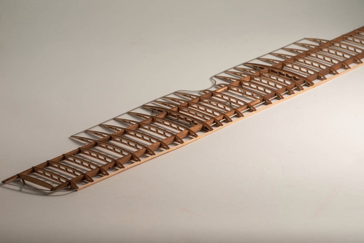
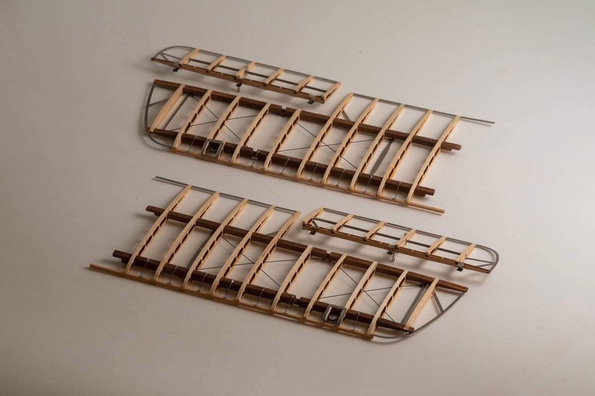
Thanks. Fortunately it is not quite as delicate as it looks. And, I think I have said this before, I am very grateful for and happy with the laser cut ribs. They fit fairly snug over the spars so that helps make the whole wing more robust.
-
Shelby 427 S/C Cobra by CDW - FINISHED - Fujimi - 1:24 Scale
gsdpic replied to CDW's topic in Non-ship/categorised builds
Wow, looks great to me! Very nicely done. It seems like there are a lot of Cobra kits out there, but I suspect that they have a lot in common with each other, and lot of the same problems. They were probably mostly created back in the 1970s too. Not sure which one would provide the best starting point for a model. The one I built....I am mostly happy with the result but there are just enough flaws that I'd like to try again, so maybe some day I'll pick up another Cobra and give it a go. Quick note on the photography...it seems like the blue base messes with the automatic color balance of your photos. The first picture that has a bit of the black background looks good to me. But many of the other pictures where there is no black background, just the blue base, the gray car has a greenish tint to me. Maybe if you have some sort of gray base, instead of the bright blue, that you could put the model on when taking pictures, you'd have truer color representation. -
Well, so much for being able to fit the completed subassemblies in a shoe box. I've been working on the upper wing and it has a span of about 21 or 22 inches. I've got about another 50 pieces of photo etch to add to the wing, plus the top and bottom of every rib will be covered with a strip of thin wood, as seen in the pictures of the lower wings. Then on to the upper wing ailerons which are pretty much identical to the lower wing ailerons. The upper wing also has some rigging to do, similar to the lower wing. Oh, I think I'll need to get more CA as well, as my bottle is just about empty. I use wood glue when gluing two wood pieces but CA to attach the photo etch to the wood.
- 91 replies
-
- 10
-

-
Shelby 427 S/C Cobra by CDW - FINISHED - Fujimi - 1:24 Scale
gsdpic replied to CDW's topic in Non-ship/categorised builds
That's unfortunate. This was a weak area of the revell kit as well. In that case, the problem was that the end of the headers did not come close to meeting up with the beginning of the side pipes. It's visible but not too noticeable looking in the open hood but very noticeable if you pick up the car and look at the underside. With your skills, I am sure you'll figure something out. -
Blocked/Missing Item
gsdpic replied to Rick01's topic in How to use the MSW forum - **NO MODELING CONTENT**
I presume that was in "Shore Leave". See the thread below. I am not an admin, just trying to help out. -
By popular demand, I have resumed a bit of work on the Sopwith Camel. No guarantees on how long that will last. I've also remembered a few of my frustrations with this kit. Ironically, I opted for this kit in part because of the additional photo etch details when compared to the Model Airways kit. But when it comes down to it, I don't particularly like working with photo etch parts. And, I've had a few fit issues with the photo etch parts as well, and they are much less forgiving than wood. Nothing major...just things like photo etch parts with a gap of 1/8th of an inch that are supposed to fit around pieces of wood that are closer to 3/16ths of an inch wide. Oh well. I've also deviated a bit from the order of the instructions. Had I been following precisely, I would have attached the lower wings to the fuselage by now. But once I do that, the half built model is both larger and more fragile. So, I am postponing that type of work...if the kit ends up back on the shelf of doom I can safely store it all in a shoe box. I've now completed the lower wings and the ailerons for those wings, as shown below. Next up I will do the upper wing, then work on the engine. Once all those bits are done, I will double back to assemble things. And in fact I also need to double back to address the rigging on the horizontal tail stabilizer that caused me issues before going on hiatus. Regardless, I believe I am about half done or maybe slightly more with this model.
- 91 replies
-
- 13
-
-
Shelby 427 S/C Cobra by CDW - FINISHED - Fujimi - 1:24 Scale
gsdpic replied to CDW's topic in Non-ship/categorised builds
Looks great. That gloss finish is very nice. I've never used 2k clear....the extra cautions/extra recommended PPE for it scares me away so I just stick with the Tamiya X-22 for now. I also recently got some of the Tamiya polishing compound. For some reason, I found that hard to acquire in the US. I added it to my Spot Model order when I ordered the MFH seatbelts to use on my Lotus 72D. Looks like the wheels fit into the wheel wells nicely now with your suspension modification. On the Revell kit I did, I had to pull the front wheels in a bit as they seemed to stick out too far. And I also trimmed down the center wheel spinners/knock offs as they were almost comically large in that kit. -
Just a quick note to say that this Sopwith Camel still resides, in the same state, on the "shelf of doom". Some day I will get back to it, as they always say..... Edit: Wow I am surprised by the number of likes this post received, thanks for the encouragement. I just finished a project (the Lotus 49) and have not decided on or started the next project. Perhaps I should drag this back out and give it a go. Though that Porsche 917K is also calling my name.
-
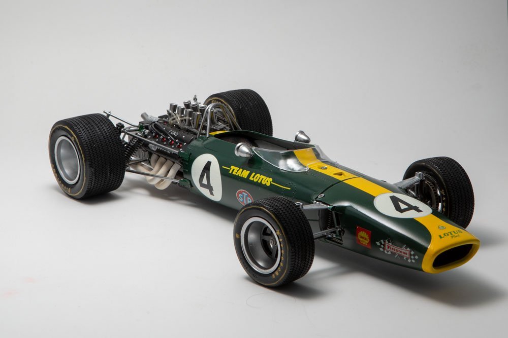
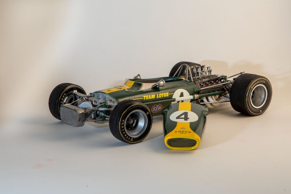
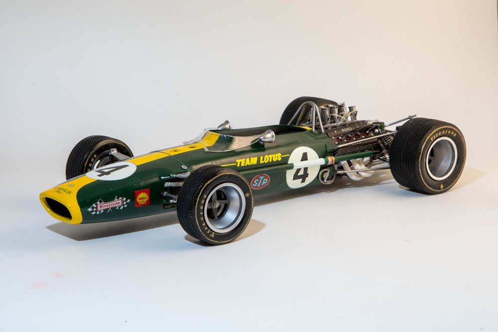
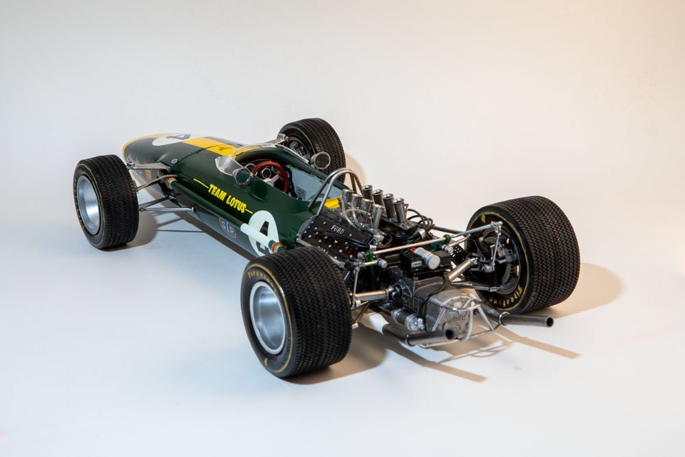
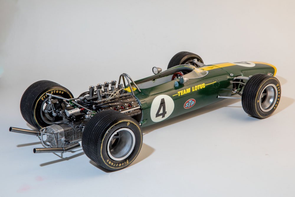
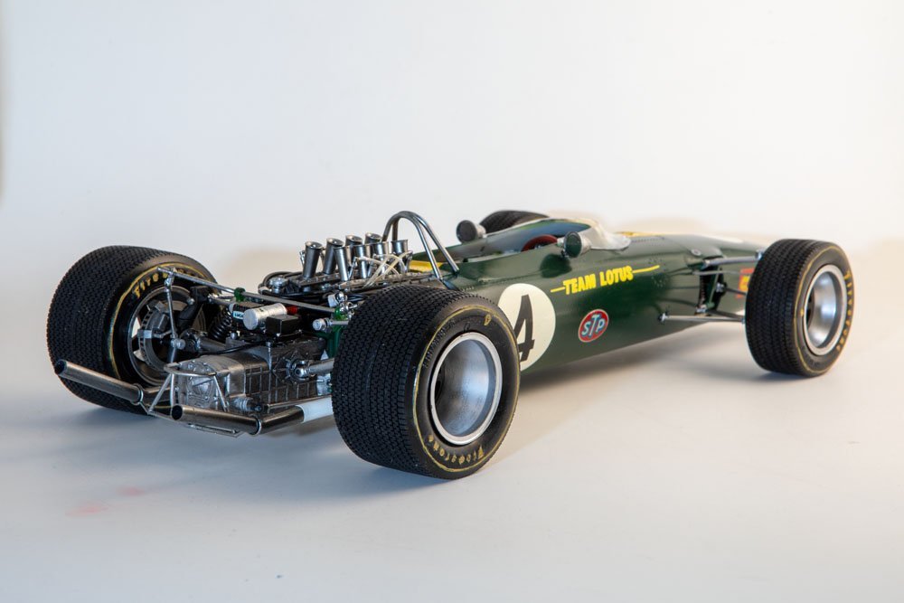
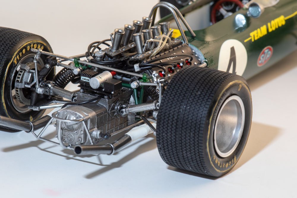
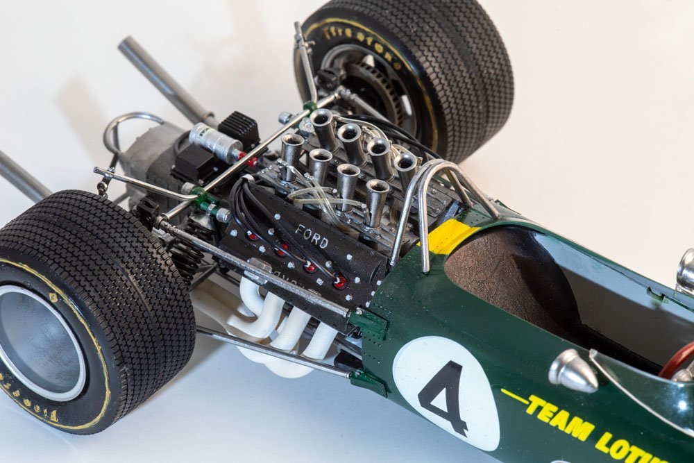
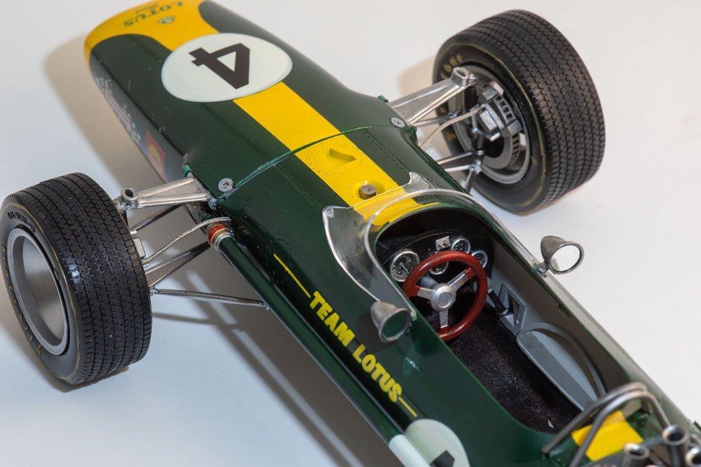
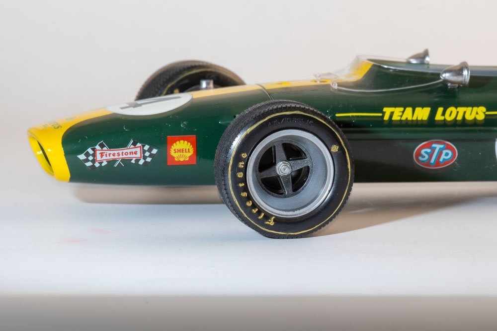
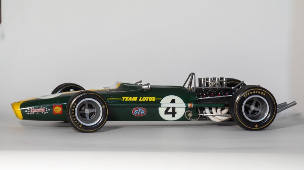
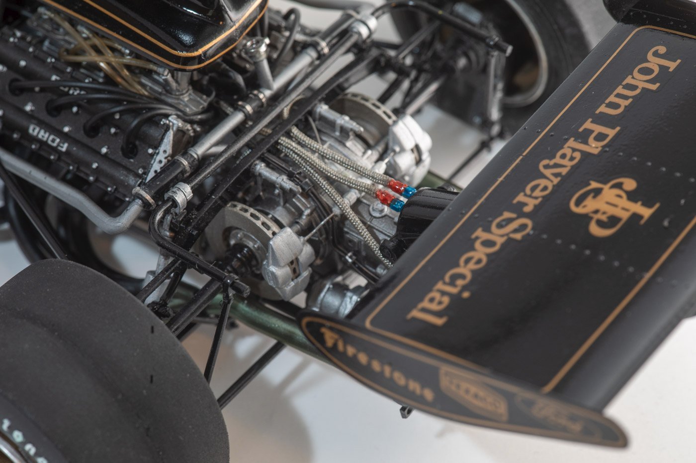
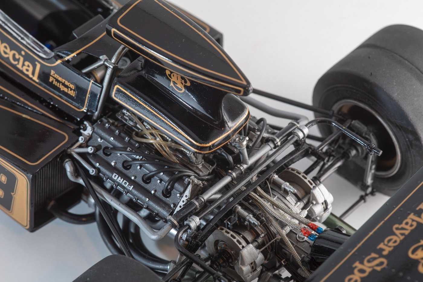
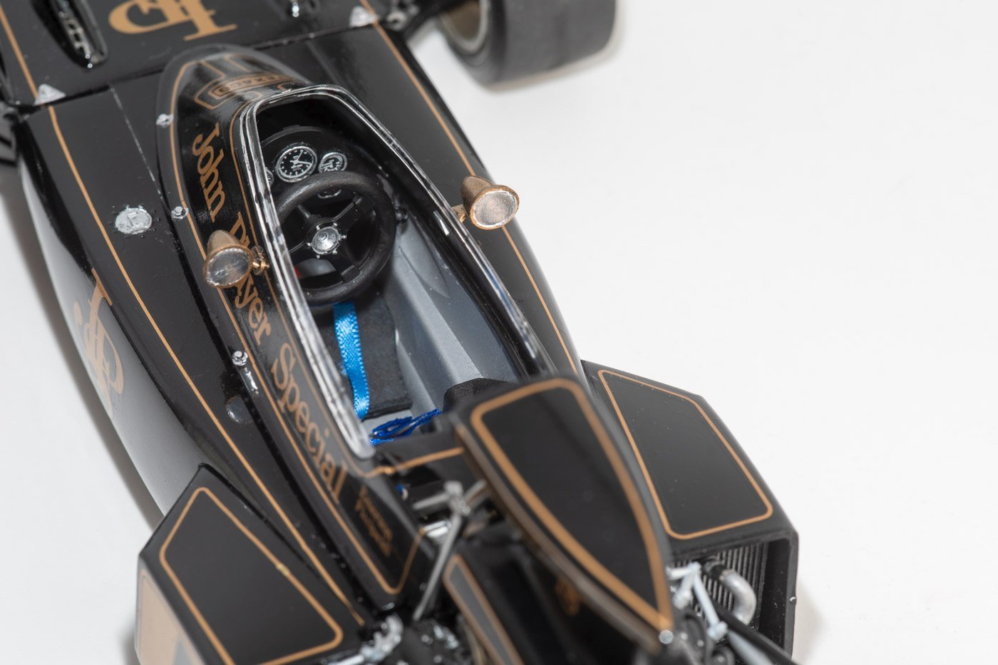
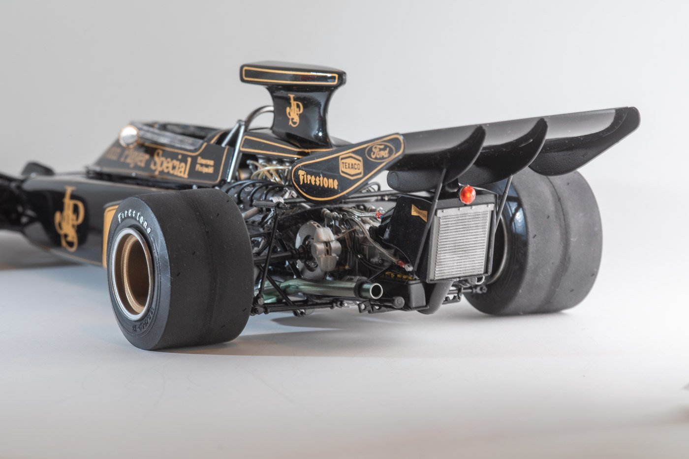
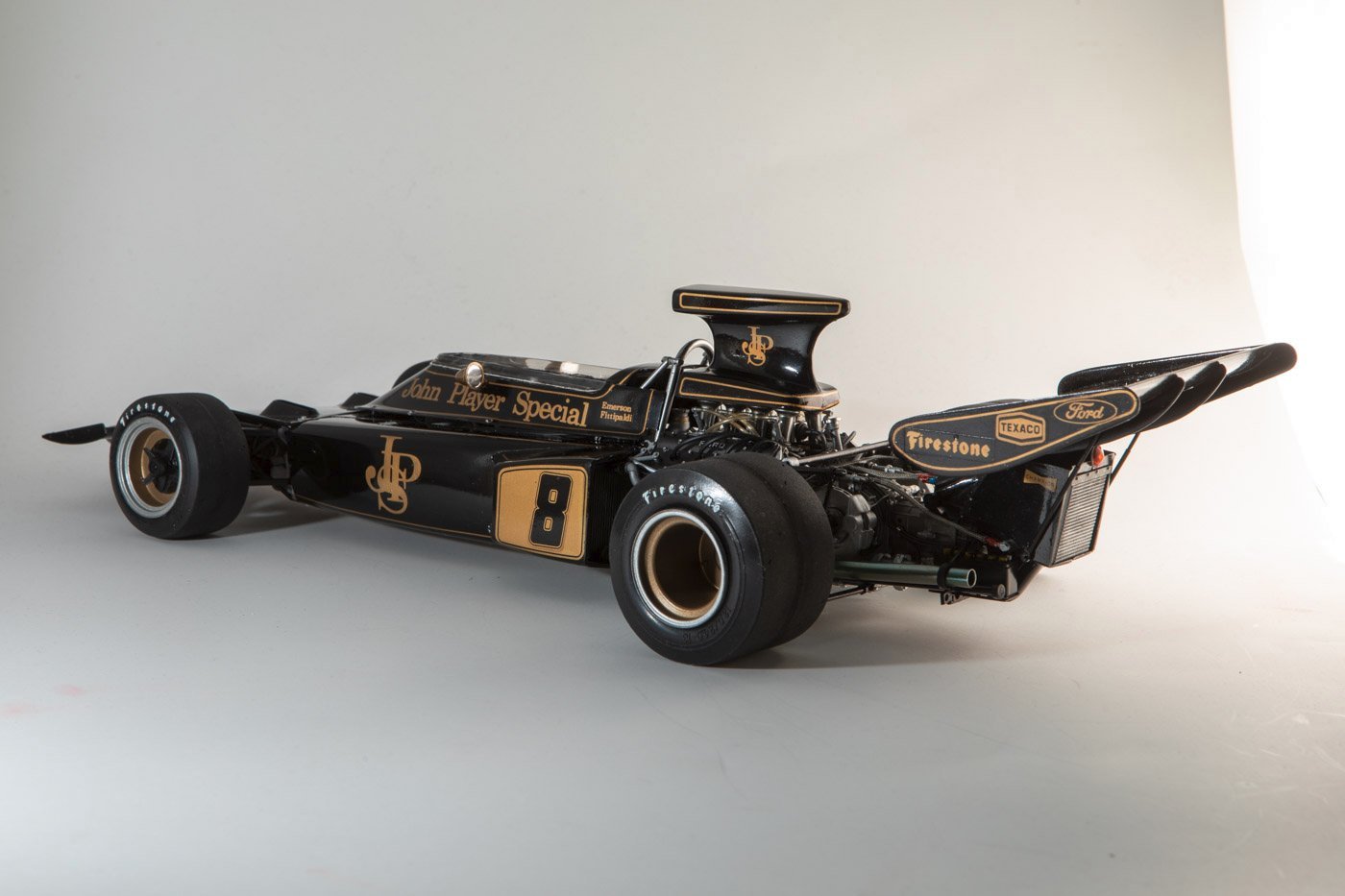
Hi All. After building the Lotus 72D, I proceeded to build the Lotus 49 from 1967, another in Tamiya's series of 1/12th scale race cars. I did not bother doing a build log, though there were times during the build I sort of regretted that choice. But I've now completed the model and done a photoshoot of it. Based on the interest in the prior build, I thought some of you might like to see it. This kit was a bit newer than the other one, though still not a recent re-issue. But it went together fairly well and I am quite pleased with the results. I mostly built it out of the box, just replacing some of the rubber/vinyl hose with braided metal lines. It was interesting that even in the model kit, you could sense how the cars were much simpler in 1967 than in 1972. And I have an unbuilt kit of the Lotus from 1978 (or maybe 1979, I forget) and just looking at the instructions and parts, it seems to be more complex still. I'll probably take a break from the old F1 cars now, though not sure what is next. Maybe even something wooden and nautical.
-
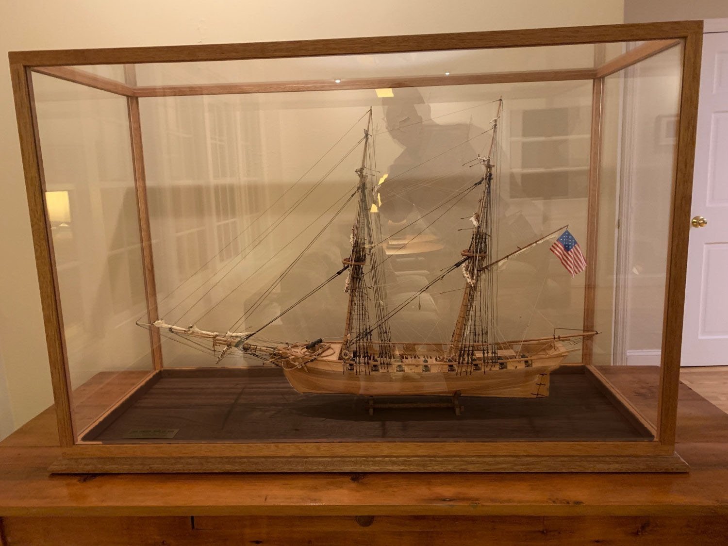
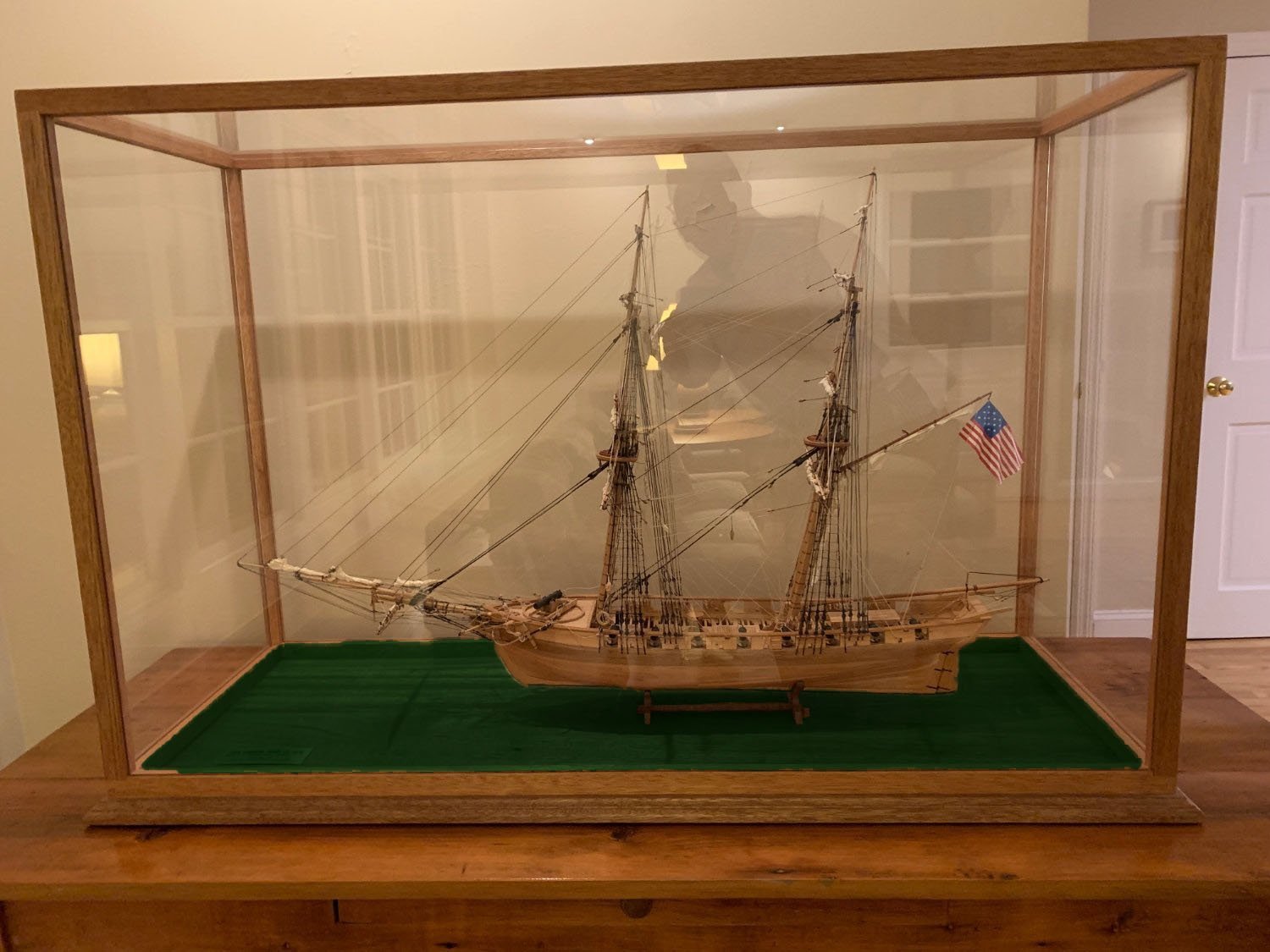
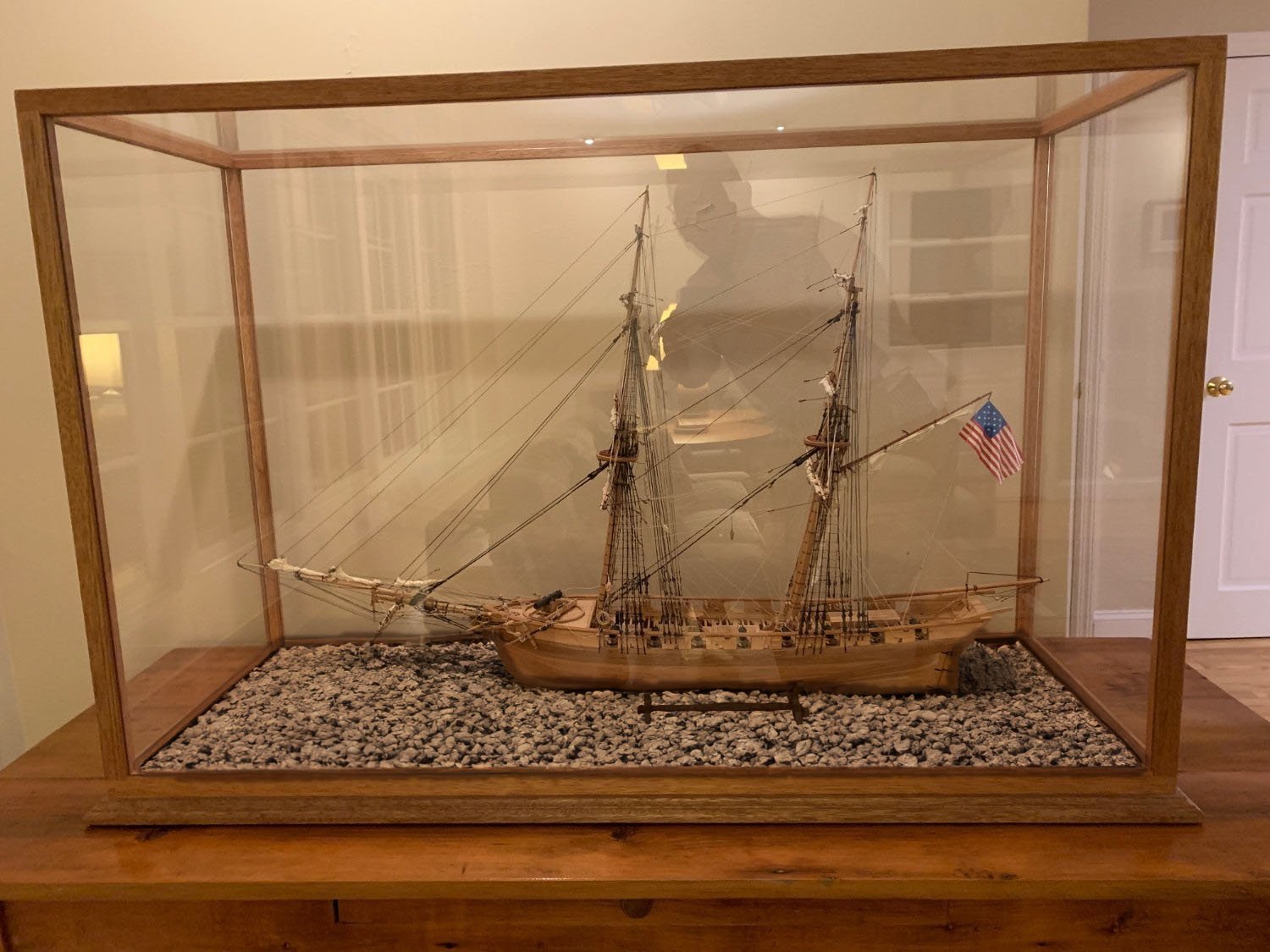
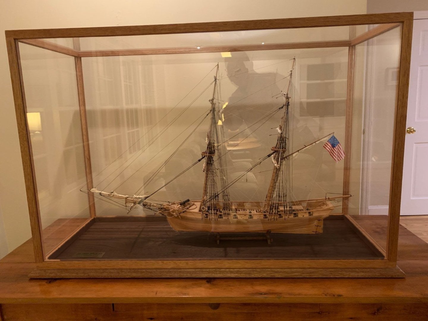
I agree that the color of the wood in the case is too similar to the color of the ship. It looks like a beautiful model but the hull gets lost a bit. Do either of these very, very quick and dirty (and sloppy) photoshop edits help? The first two I just changed the color/lightness of the base and the third I attempted to use the new "generative fill" tools to put gravel on the base, but I had trouble getting it to generate gravel as small as I wanted.


-
Shelby 427 S/C Cobra by CDW - FINISHED - Fujimi - 1:24 Scale
gsdpic replied to CDW's topic in Non-ship/categorised builds
I am both a little disappointed but also excited to see what alternative you have in mind. I did the traditional blue with white stripes on mine though when done I decided my stripes were a little too wide. I defined them with 10mm wide Tamiya tape but they should have been more like 8 or 9 mm. Looking good so far; interesting treatment on the engine block. -
It is still a bit difficult to understand what the problem is. If you are referring to gluing the frames to the base piece, there are various ways to get them square and vertical. Some people have metal blocks or metal squares that are perfectly rectangular that they clamp the frames too, others use lego blocks as their reference for 90 degrees. I built this kit many years ago before I discovered MSW. I do recall that the laser cut plank fit was not exact. In my case, the ends extended past the stem or stern a bit, at least in some cases, and they were trimmed and sanded after the hull was built. Also, I recall it being easy to get confused about which end of the plank was the bow end and which was the stern end, which also affected the fit. There are a few other build logs for this kit that you might want to search for and take a look at to see if any of them provide clarity for you. You'll see that some others struggled a bit with the planking as well.
-
I am certainly no expert, but this hull shape appears to be a bit similar to the hull shape of the coast guard cutter that I was just looking at the build log for, by @drobinson02199. You might be able to "plank" at least parts of the hull with large flat sheets of either plywood or styrene instead of individual small planks. I think John/Jim Lad was suggesting a similar approach when he mentioned using ply. The build log, linked below, might give you some ideas for how to construct your hull. Note that kit was designed to allow RC operation and that probably dictated the open frames to allow room for the RC equipment but it may be easier to use solid bulkheads and the large false keel/backbone as you did with your prototype. This looks like an interesting project of an attractive boat, and it has a bit of extra personal meaning for you. Good luck!
-
Shelby 427 S/C Cobra by CDW - FINISHED - Fujimi - 1:24 Scale
gsdpic replied to CDW's topic in Non-ship/categorised builds
Sweet, I look forward to following this. I recently built the Revell 289 Cobra race car model. It was a bit of a mish-mash. The chassis/suspension seemed to represent a 289 (i.e. transverse leaf springs) but the body was a 427 body....there was even a "427" logo molded into the front fender. The model as a whole was rather challenging. Based on the info at scalemates, it does not seem that my Revell model is related to this Fujimi one (though Revell did sell a version of this model). So, it will be interesting to see how it goes together. -
Focus Stacking
gsdpic replied to Dennis P Finegan's topic in Photographing your work. How to do this.
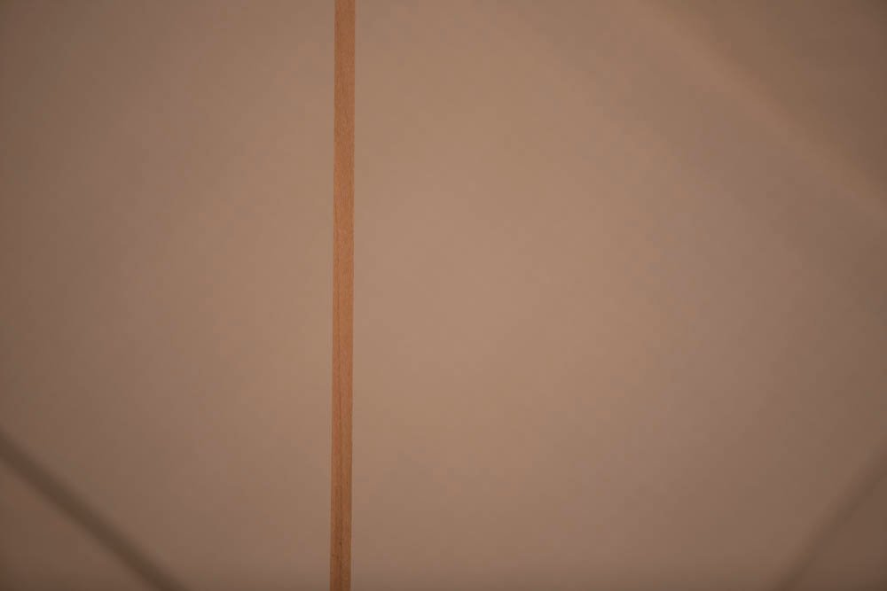
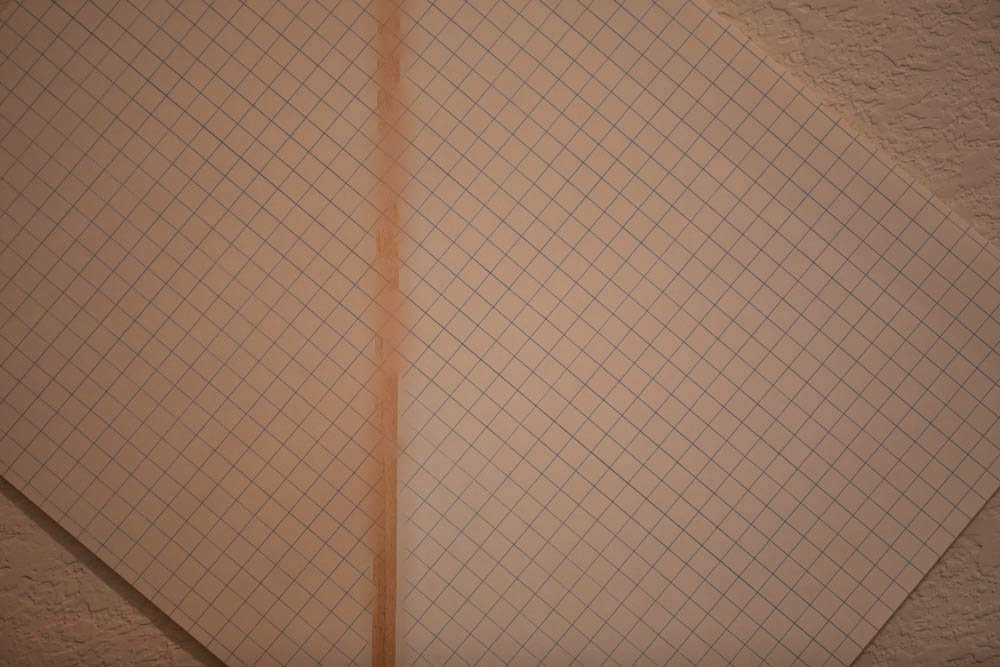
To a great extent, I think that is a limit of focus stacking. Imagine (oh, wait, you don't have to imagine, there are pictures below) an object, say a strip of basswood, sticking up in front of a piece of graph paper. It should be enough to take two photos, one focused on the stick and one on the paper, to do a focus stack. But when focused on the paper, the stick becomes a blurry smudge that is larger than it is when it is in focus. So the bits of graph paper that are immediately next to the image of the focused stick are at least partially obscured in the graph paper image. So, when the focus stack is done, there are parts of the graph paper that are not clear and unobscured in either image. I did the below experiment, all images taken with a 180mm macro lens about 5 to 6 feet from the objects, at f/3.5). The stick and graph paper were about 12 inches apart. Note that at 6 feet, f/3.5 180mm, the actual depth of field is less than one inch. First, the two source files, focused on the stick and on the graph paper. Now, the results with photoshop (the current 25.0 release). You can see it struggled. It is possible that I did not quite nail the focus on the stick but I thought it should have been close enough. Photoshop just creates a mask to combine the two images so everything here is from one image or the other with no blending. It missed much of the image focused on the stick, and you can see the places where it got the focused stick, the blue lines of the graph paper fade out near the stick, due to the blurry smudge in the graph paper image. Here's the results from Helicon Focus 8.2.2 (also current version). You can see it did a much, much better job, but the graph paper lines still fade out next to the stick. Interestingly, you can also see through the stick to the graph paper lines behind it to some extent, much like in the source image that was focused on the graph paper. I might have to try again with better focus on the stick to see if that helps photoshop any.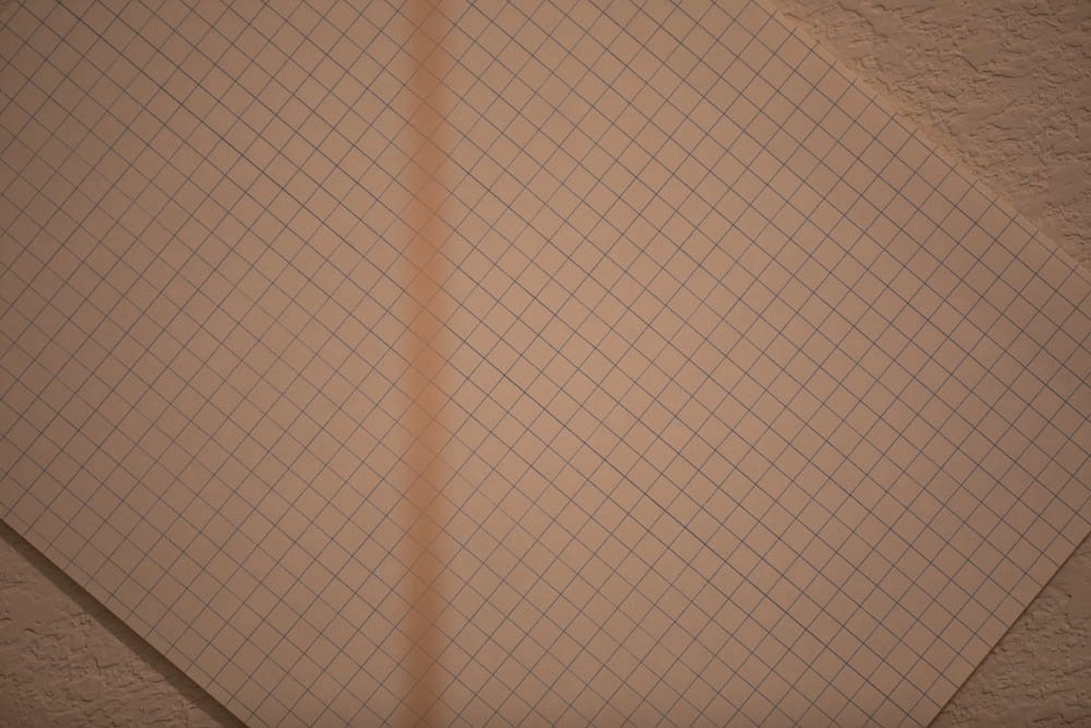
.jpg.28966ed50460c99da2443ff191733b38.jpg)
-
Bugatti Type 35B by CDW - FINISHED - Italeri - 1:12 Scale
gsdpic replied to CDW's topic in Non-ship/categorised builds
Nice! As every one else has already said, really well done. -
Excellent job painting/weathering the barrels!
-
Mini self contained airbrush
gsdpic replied to Bill Hudson's topic in Modeling tools and Workshop Equipment
I keep seeing this topic pop up from time to time. Perhaps the question would have been better asked with a link to the actual product. I've seen such a thing at Micro-mark, so here's the link: https://www.micromark.com/Micro-Mark-Self-Contained-Portable-Broad-Spray-Airbrush That one is slightly different from the one pictured above. The Micromark unit has a "MAC" valve and a slightly more ergonomic looking air tank. I've not used one, but to answer some of the questions above, based on my understanding of the description and video that micromark has... - The airbrush part is just a standard air brush that can be detached and used with a normal compressor. The unique part is the integrated tank/battery powered compressor. The air brush is likely a Chinese made imitation of one of the standard types which can be had for 40 bucks or less. The one with the micromark kit looks a lot like the Neoeco NCT SJ81 (https://neoeco-airbrush.com/products/neoeco-nct-sj81-gravity-feed-dual-action-airbrush). Neoeco is an OEM for a lot of places that resell airbrushes. I have suspected they are the ones who make one of the other airbrushes that micromark sells though that is just a guess. - The part you hold has a small tank, battery and compressor. One battery charge lasts approximately 40 minutes according to the page. Since it has a small tank that should keep the pressure relatively stable until the battery expires. I have four concerns about it. 1. The same concern that wefalck has....it seems like it would be awkward to hold and use especially if attempting some detail work. 2. It does not appear to have a method to adjust the air pressure or even a method to indicate what the current pressure is. I am no airbrush expert and have only used one in the last few years (mostly on plastic cars) and even I frequently adjust the air pressure based mostly on the type of paint used, so this seems like a big issue. 3. It seems a bit like a solution in need of a problem, at least for model building. How often do you really want the air brush to be portable so you can use it anywhere in the room? For me the answer is never, so it is not an issue to be tied to a compressor. 4. It has no moisture trap....the micromark page acknowledges this and says one could be put between the tank and the airbrush though that would likely make it even more awkward to hold. -
Looks like a handsome tug. Do you plan to do RC or just a static model?
-
The instructions are just a few PDF files on the DVD in my experience (with the Sopwith Camel). If you have no computer with DVD, the PDF files can be downloaded from the AL web site. Having said that, it is still a little bit of a pain to use that vs a paper manual though I certainly understand why they went that route.
-
Lotus 72D by gsdpic - FINISHED - Tamiya - 1/12
gsdpic replied to gsdpic's topic in Non-ship/categorised builds
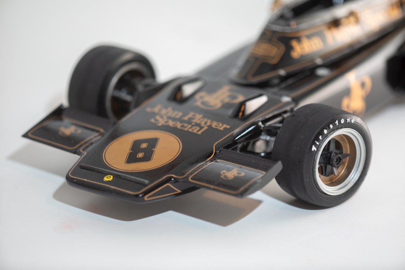
Thanks to everyone for the comments and likes/wows. @kgstakes the "wear" on the tires was mostly my marginally successful effort to remove the mold line running the circumference of the tires in the middle. Being an old kit, the tires felt a little squishy and fragile so I did not want to push it too far. When cleaning up, I also found one part that did not make it on to the model. Not sure if I can retrofit it now. The shift rod to control the transmission is shown in step 35 with a note saying not to actually put it in place until step 43. Of course by the time I got to step 43 I forgot about it. Not clear if I can get it in place now with the model complete. Oh well. I am also still undecided about the hand painted lotus logo at the front of the nose. There was a small, molded in raised circle there but no decal provided for it. Looking on the web, the car seemed to either have a lotus logo there or a gold "JPS" logo. I chose to try to replicate the yellow and green lotus logo but I sometimes think it looks a bit out of place. I guess I'll leave it but I've been tempted to try to change it at the risk of screwing it up. -
Lotus 72D by gsdpic - FINISHED - Tamiya - 1/12
gsdpic replied to gsdpic's topic in Non-ship/categorised builds
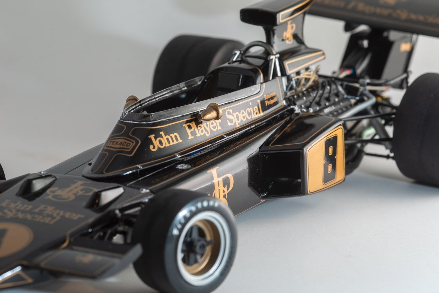
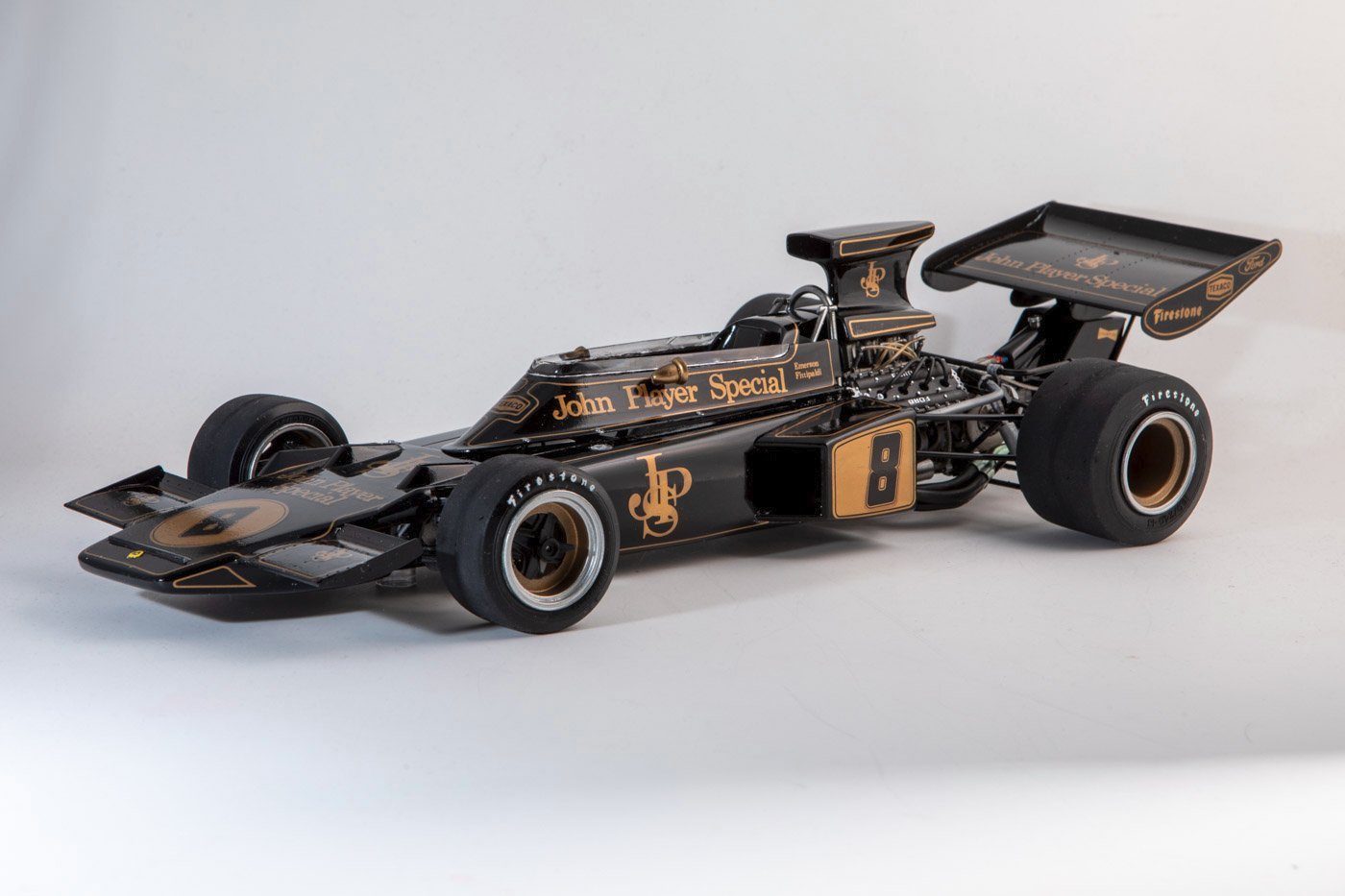
I am now declaring this one complete. For the first time for a plastic car model, I feel like I should get/make a case for this one. Thanks to everyone for following along, hitting the like button, providing comments and suggestions, I appreciate it. Below are pictures of the finished model. This model is quite large....almost too big for my homemade macro photo booth which is basically a cube of 18 inch PVC pipes. In a few cases I used (for the first time) the Photoshop "generative fill" to fill in corners and edges of the white background where the real thing was not large enough, revealing the wall behind it. That's kind of like using a sledgehammer on a fly I think. I also had to switch away from my 180mm macro lens for the overall shots because I could not get far enough from the model to include the whole thing in the frame.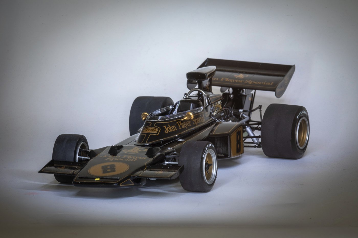
- 48 replies
-
- 11
-

-
-
Lotus 72D by gsdpic - FINISHED - Tamiya - 1/12
gsdpic replied to gsdpic's topic in Non-ship/categorised builds
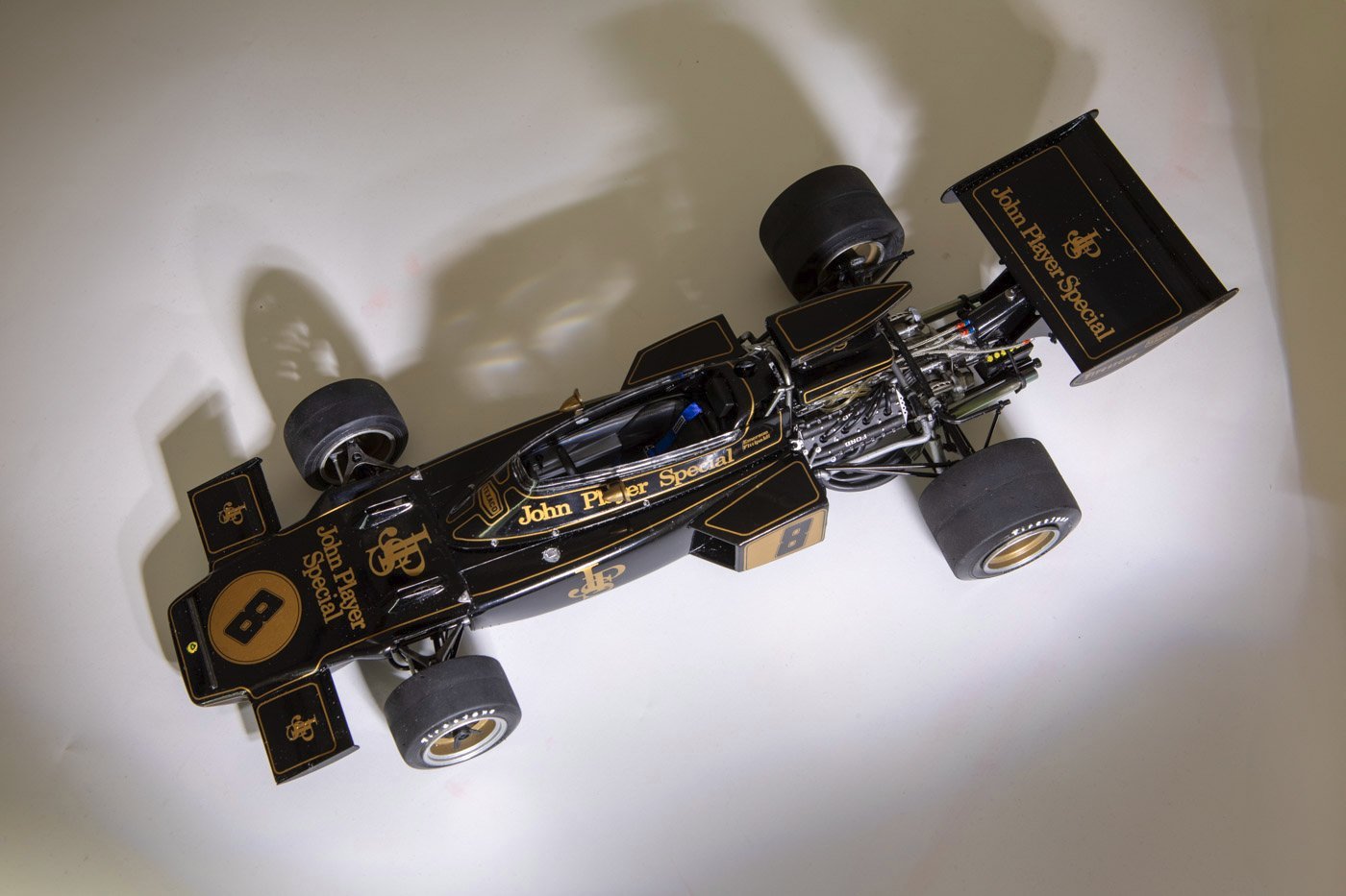
Thanks as always for the likes and wows and comments. I appreciate it. I am done except for attaching the oil lines to the oil cooler (seen here draped over the rear tire) and doing the rest of the flat black paint on the clear part. I did just a small section and it is an improvement, so I'll do the rest more carefully. As for the oil lines, I want to let the glue holding the wing cure a bit more, as that is a rather large piece hung off the back with four fairly small attachment points. So tomorrow I'll wrap that up and then do a more extensive photo shoot. But for now here is one teaser picture. Under the car, you may also see a little bit of one of two clear plastic disks on the underside of the car, supporting some of the weight of the model. I guess they did not trust the suspension pieces to hold the car indefinitely. Probably a good thing. I am also debating gluing the air induction scoop or not. The instructions indicate to glue it but it will cover up some of the engine. But if you don't glue it, the slightest bump will knock it off. The front cowl and the upper part of the cockpit both snap on and will be ok unglued. The cockpit part was a bit warped, and still is a tiny bit, so I thought I might have to glue it down as well. But I think it is close enough that it will stay on without the seams/gaps being too unsightly.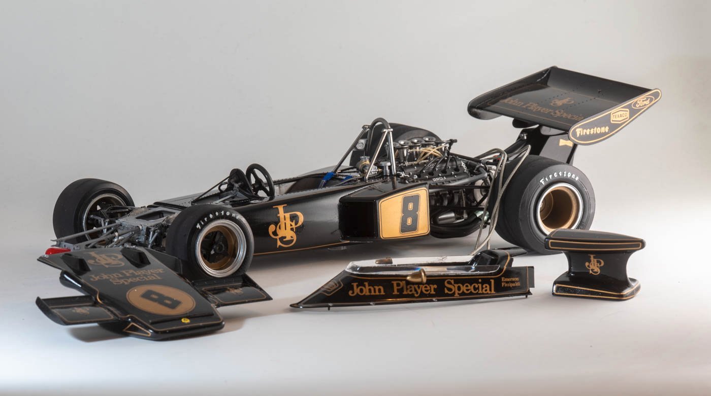
- 48 replies
-
- 10
-
-