Timmo
-
Posts
609 -
Joined
-
Last visited
Content Type
Profiles
Forums
Gallery
Events
Everything posted by Timmo
-
Pandora by marsalv - FINISHED - 1:52
Timmo replied to marsalv's topic in - Build logs for subjects built 1751 - 1800
Superb -
Great colour with that blue Jason. I hear what you say about tamiya acrylic and for that reason I've only ever sprayed it but I can't see any brush marks on yours. Those steps and rails look great. Love the full hull shot. She's a ship of great beauty.
-
Nice name there Joe. Sophie was a contender for me as I've got a daughter by that name, however with three girls I didn't want to explain to the other two why the boat wasn't named after them! Great links to the war of 1812 for an American with that vessel. That stern name plate looks very good and crisp little pumps there. Looking forward to more.
- 136 replies
-
- 2
-

-
- caldercraft
- Cruiser
- (and 2 more)
-
Lots of progress there Joe. Those platforms look great. Good move on the carronades, it opens up a world of vessels to depict.
- 136 replies
-
- 1
-
-
- caldercraft
- Cruiser
- (and 2 more)
-
That's a glorious bow Chris. The head rails really complement the figure. Well done.
- 290 replies
-
- 1
-
-
- confederacy
- frigate
- (and 1 more)
-
That's a handsome wheel there Joe and a big improvement. BE, good to know about the colour of the rudder fittings. I see a paint job on these in Harrier's future.
- 136 replies
-
- 1
-
-
- caldercraft
- Cruiser
- (and 2 more)
-
That's a superb interpretation of the stern there Jason. It's great to see the steps you've taken to bring it closer to AOTS and it sure makes a difference. Can't wait to see those carved figures - you know you want to...
-
Thanks Jerry, the side mounted servo is something I hadn't considered. I understand the concept of a drum enclosure to trap slack line but I'm with you in that it feels like there's too much reliance on what would have to be close tolerances for it to work consistently. Plenty of trial and error ahead. Jason. You are right about the jackstaff hindering the headsails. It'll have to go for sailing days and slips out easily enough.
-
Big improvement there with the cheeks Joe. Nice work.
- 136 replies
-
- 1
-
-
- caldercraft
- Cruiser
- (and 2 more)
-
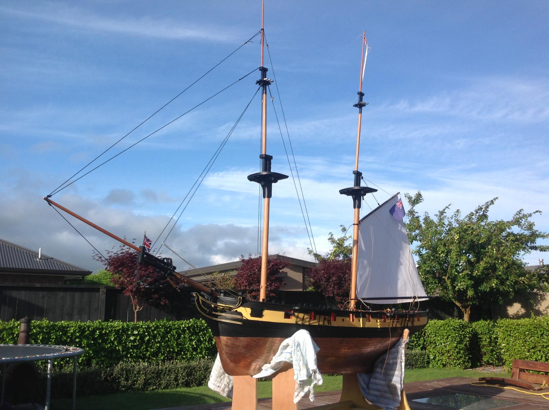
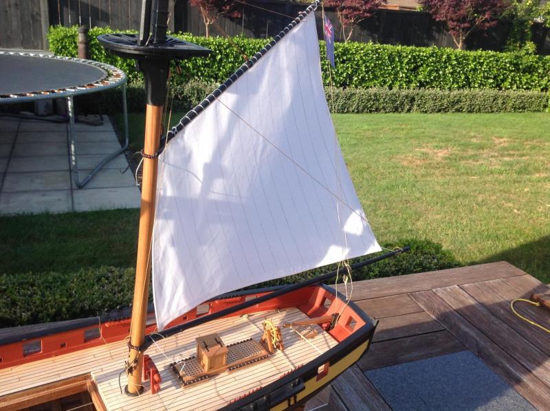
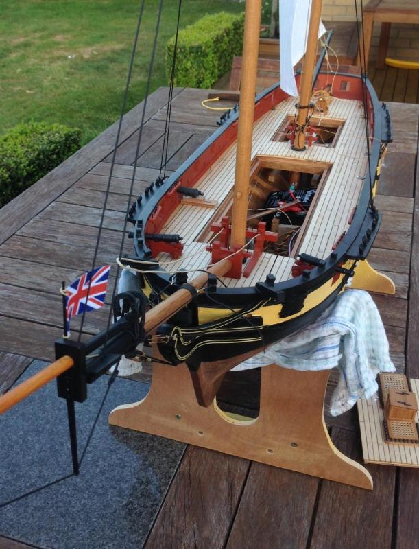
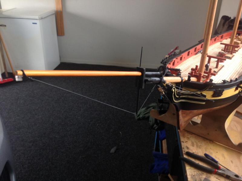
Happy new year all. Some of the cool bits that'll make this thing go have been either completed or temporarily knocked up in the last month or so. First among these is the steering rig, which was built up as per the earlier test. The servo drum was wound tight enough and is close enough to the fairlead up to the deck that it gets around the issue of tension. This all works quite well and gives about 45 degrees of rudder each direction. This was also the first opportunity to wire up the battery, receiver and use the transmitter. Lots of fun although my wiring needs some work. I've also filled my ballast tube with about 9kg of lead which works well in the bath but is awaiting testing in a friend's pool. The threaded rod mounts have been left long to allow it to be adjusted to allow it to sit either flush to the keel or hang below to increase stability if needed. This will be sorted once the amount of stiffness needed is worked out with all sails on. The other interesting bit has been rigging up a temporary spanker. This is pretty much a test of materials for the sail (not the final version) and to see how it all behaves with the rigging. It sprang out of just wanting to see some flags rigged. The servo is a simple arm arrangement with (temp arm) and works well. I wanted to use a double block arrangement on the boom as per the original but after some experimentation realised this also doubles the pull of the sheet needed for the same distance of travel. This is possible with a winch servo but results in issues of keeping tension on the line to stop tangles on the drum. Simple seems best, hence the arm and a single sheet with a dummy block for looks. I've got a plan to jury rig the foresails and servo and try a small, controlled maiden voyage so have installed some temp stays on the foremast in preparation for the this. These follow the same tent guy rope style of the martingale stay to allow for adjustment. It works so well I'll likely keep it but tidy it up to make the little slides less noticeable. This can easily be taken off as before the masts can be permanently with shrouds etc as I've still got to make underdeck blocks to guide the yard braces up from the servos. In the pic below you can see the lines for the foresail sheets emerging from the fairleads in the forward bits. I've added a little jack staff on the bowsprit with a union flag. I'm not sure it is accurate so comments welcome. A little history of the real Harrier's adventures and reason for the blue ensign to come in a future post.


- 141 replies
-
- 13
-
-
That's a good looking deck Joe. Nice tidy work on the treenails.
- 136 replies
-
- 1
-
-
- caldercraft
- Cruiser
- (and 2 more)
-
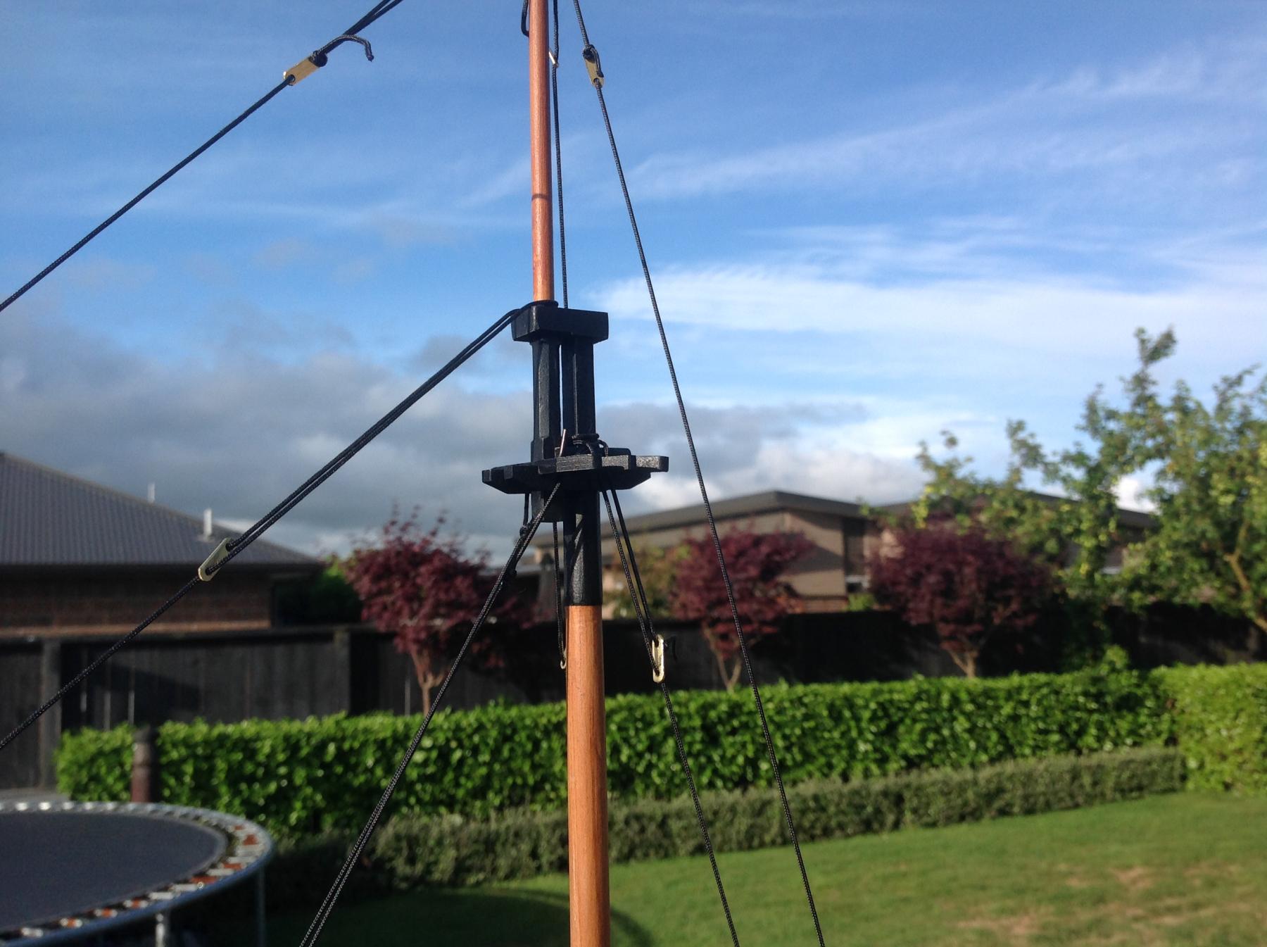
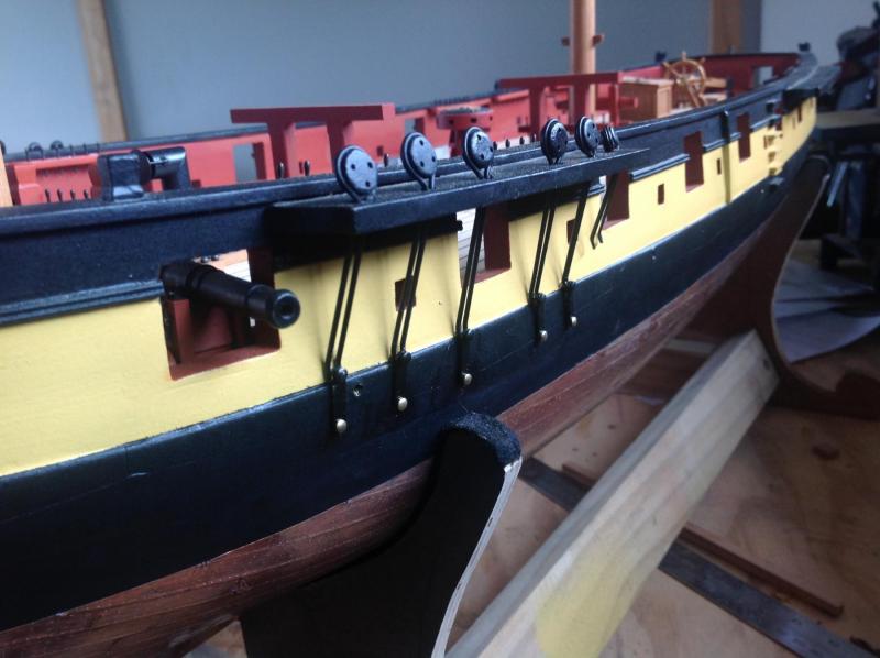
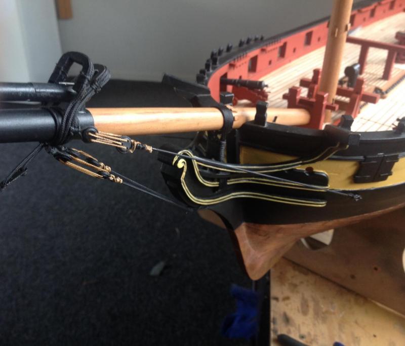
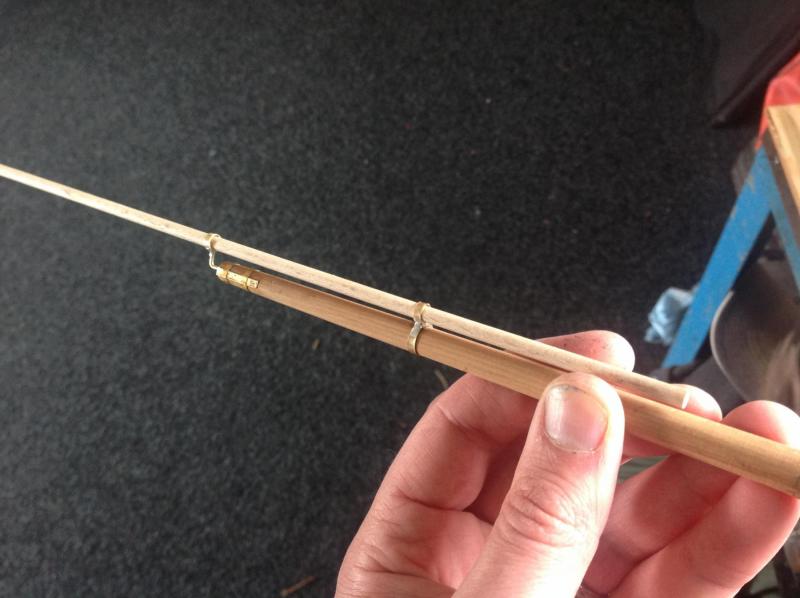
The chainplates have all been completed with about half installed. These were made as one piece of brass rod bent to shape on a simple jig (nails in a board), silver soldered and held in place with a small brass plate pinned into the hull side. It's not the multiple chains of the real thing but it's a good compromise between looks and strength. In somèthing of a milestone the first elements of rigging have been installed with the stand rigging of the bowsprit added. This is a range of synthetic braid from about 2mm on the forestay collars to 1.6 on the gammoning and 1mm for things like the bobstay and bowsprit shrouds. They range from 25-150kg breaking strain. The hemp lines are .5mm line dyed with some left over outdoor decking stain. Once installed it's all very solid with the load spread across multiple lines. It makes you realise what an exercise in physics a sailing vessel is. The forestay collars were cut from sheet acrylic left over from the clear rudder extension. Timber at that scale would not be strong enough. The martingale stay is added with an adjustable plate to change the tension on it. It's like a tent guy rope. The jib boom is removeable for transport so the stays attached can be slipped off and tightened again once reattached. One set of studdingsail irons have been made from brass for the main yard. These will serve no functional purpose but it's the sort of little detail that'll make the rigging look busy and real.
- 141 replies
-
- 18
-
-
A very helpful vid there Gerry. That brace moves very smoothly. I'm not far off mast installation and having to think about such things so I'd be very keen to think only one active set of braces per mast would do the job rather than having multiple drums etc. Would I be right in thinking if it'll work for a larger three master vessel like yours it'll work well for the Harrier brig with the same servos?
- 97 replies
-
- 2
-
-
- macedonian
- frigate
- (and 2 more)
-
ancre La Salamandre by tadheus - 1:24
Timmo replied to tadheus's topic in - Build logs for subjects built 1751 - 1800
That's a lot of detail to hide under the deck Pawel. A master builder at work there with the confidence to not have to show it off. Well done -
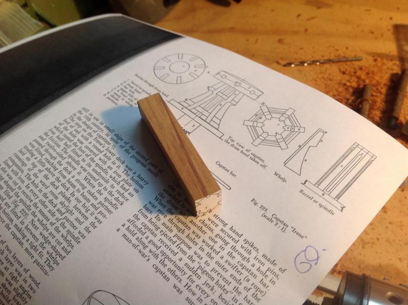
Thanks for the kind words all. Progress continues with the yards with four completed while I await more brass rod to finish the chainplates. Pics will come soonish. Once the yards are sorted I'll arrange the passage of the yard braces from the servo positions up through the deck and to the yards. This is one of the most important bits of making it all 'go'. I'll be stealing ideas from luminaries like Gerry Todd for this. Once the underdeck blocks and tubes for this are done I can install the masts. This will be a crucial step and mean I can revisit the square sails later on and possibly just get the driver and foresails rigged to get Harrier on the water in a partially rigged fashion. It's coming up 20 months into the build and time we saw some sailing action but the mad dash to Christmas is here and progress may slow. Jason, if you ever want to borrow the Irene book, just shout.
-
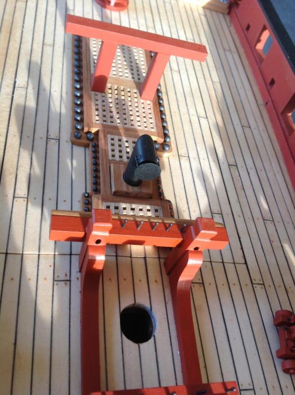
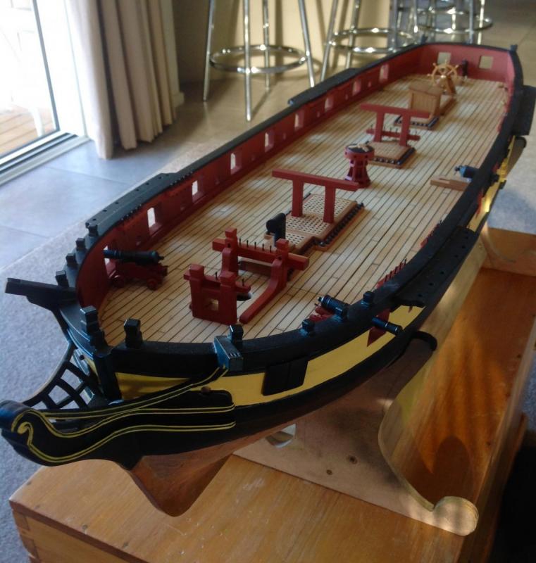
The hawse bits were made with bass tube running vertically through the uprights. . These exit facing forward and will allow the lines for the foresail and jib the travel from servo to sail. You can see the holes here The aft face of the bits has a single timber half round facing as per Petejus, his was to stope hawse chaffing. The brass chimney is painted and sits loosely to cover the ballast rod and nut when installed. . Also most of the rest of the deck furniture is installed minus the little raised windlass (proper name escapes me) aft of the main mast and the pumps. Also pinrails and belaying pins added. Chainplates are next. His majesty's brig Harrier as she stands...
- 141 replies
-
- 15
-
-
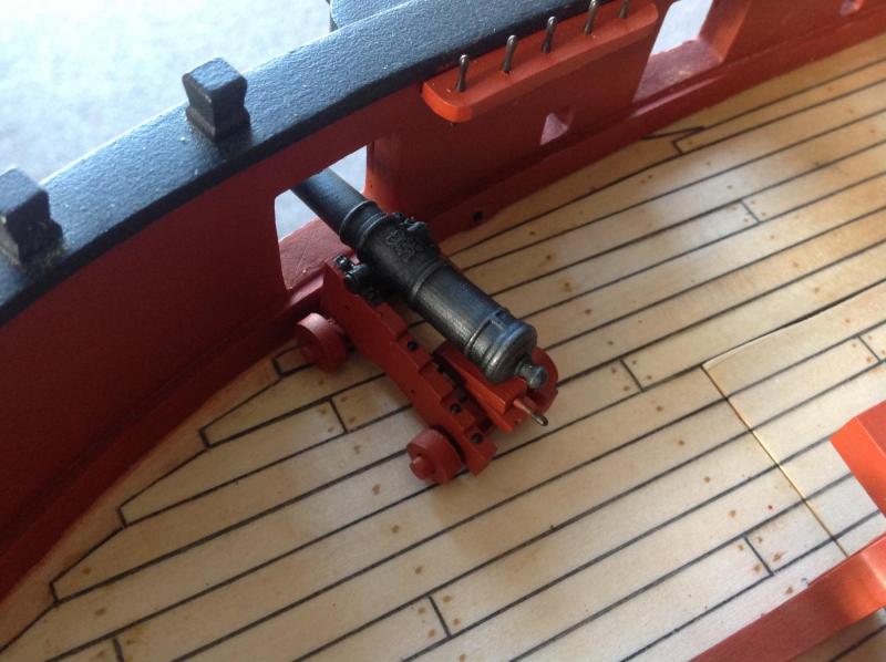
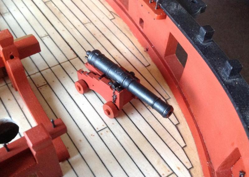
The 3D printed long guns are painted and finished minus the rigging blocks. These are quite cool. Thanks to a Tim Bowman for the files. The crest pops out nicely with a light rub of graphite. The retaining chaining is from RB models.
- 141 replies
-
- 11
-
-
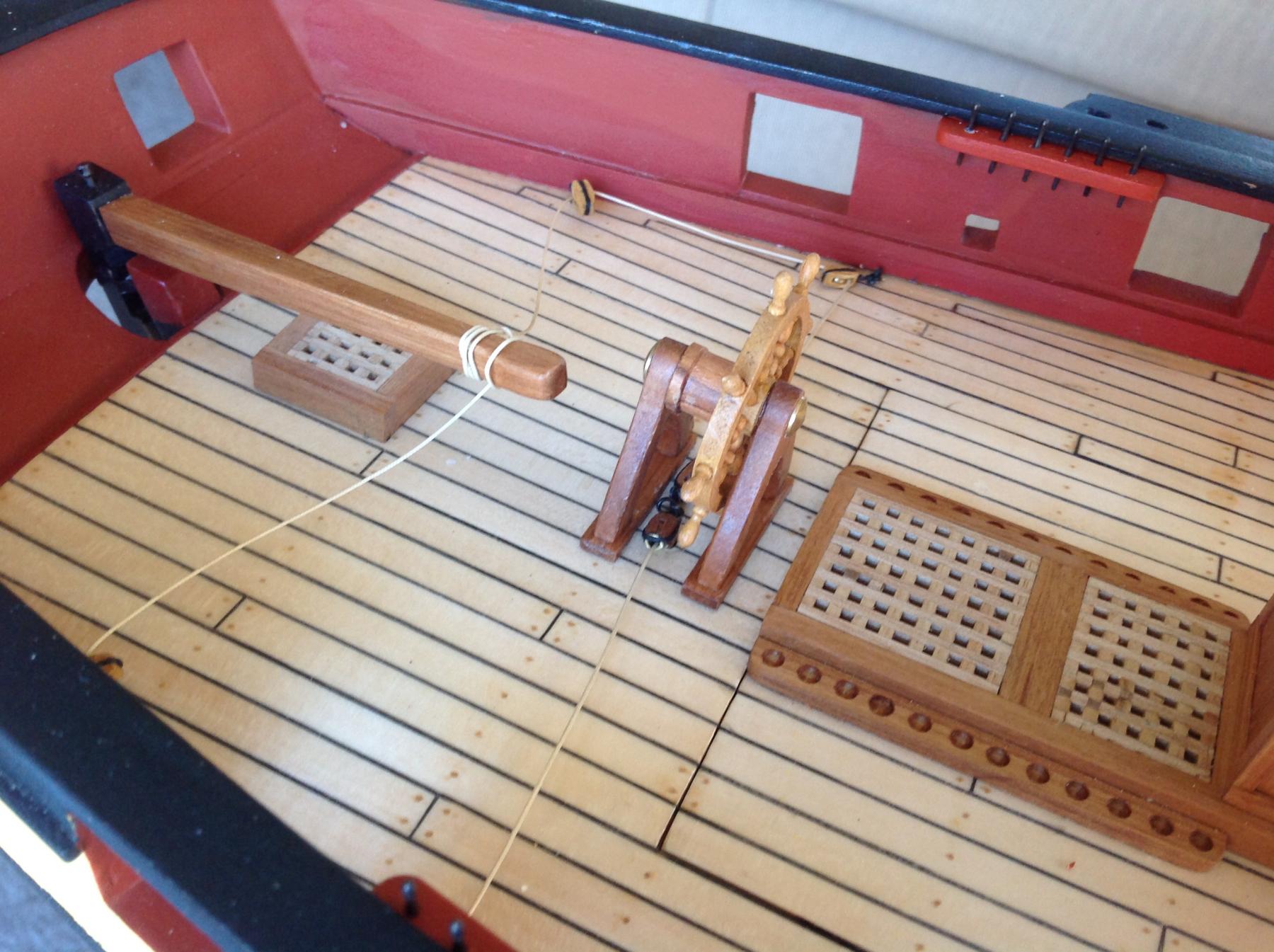
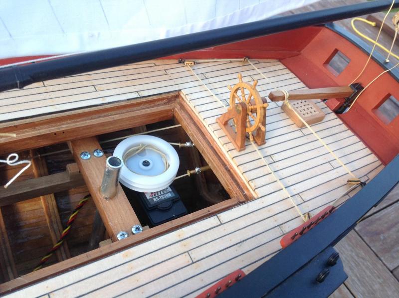
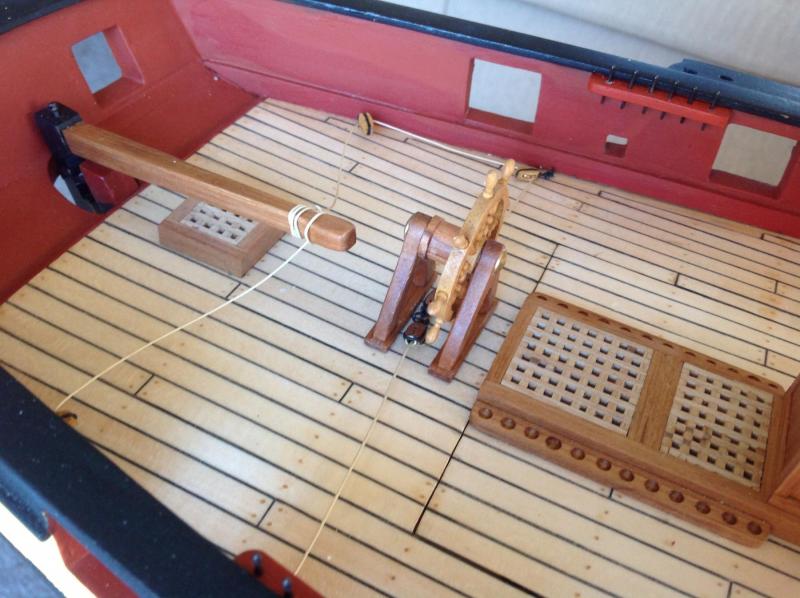
In other developments.... the steering gear has been completed with a wheel from RB models mounted on a bespoke frame. Brass tubes protrude through the deck under the wheel to deliver the cable from the servo. These are topped with wooden blocks cut to hide the tube. A fake cable will run around the wheel drum and down to the fake blocks. The live line will run from the tube/ block assembly and out through two working blocks to the tiller. I wanted I keep the exit tubes as near the centreline as possible to avoid water across the deck getting into the hull. There was a bit of test fitting to get it so the rear most carronade wasn't fouled. The proper arrangement would have another block on the tiller for extra purchase but this seems to work best without the added complexity.
-
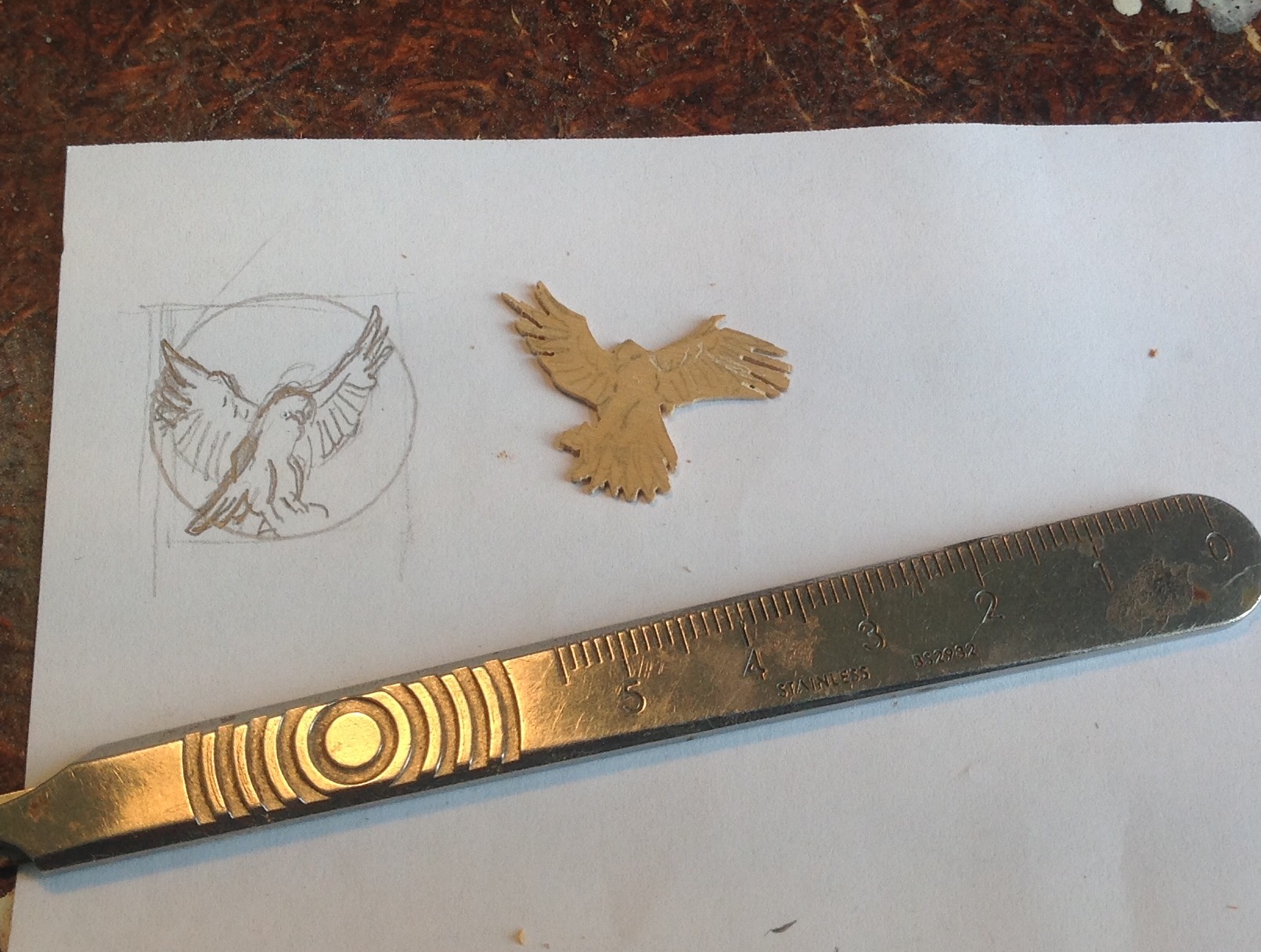
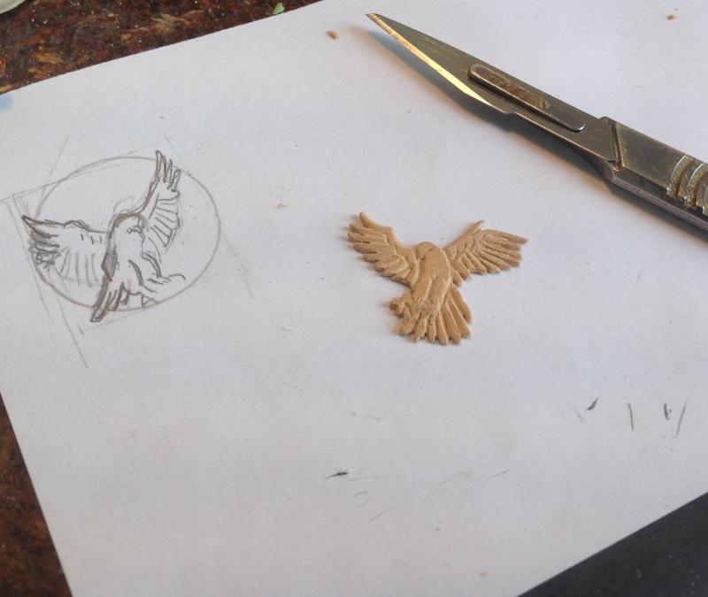
Thanks Mark, it was a bit of a test to see if carving decorations on future projects would be feasible. This is only two dimensions but an encouraging result. The base circle made of ply is a little smaller than it should be due to measuring only once rather than twice before cutting but it looks ok so not worth changing.
-
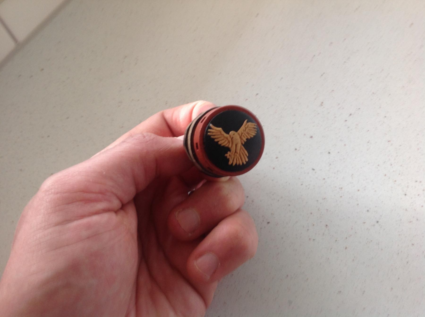
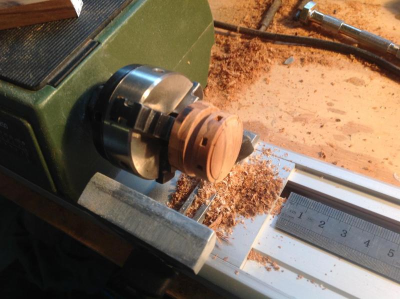
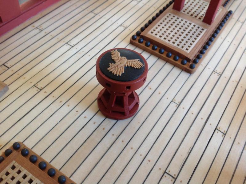
A bit of progress. The capstan drum was turned on the proxxon lathe with the square holes cut with a square and file. The axle was a simple square section filed and planed to shape with the flanges cut on the jigsaw. The fancy finishing touch is a little bespoke harrier hawk, to personalise the vessel, carved for the top of the capstan drum. This was sketched up using a bird photograph from google as a reference and draw onto a piece of Castello boxwood. It's the first time I've used a piece of this and I was very impressed with its density and ability to hold fine detail. The shape was cut with he jigsaw and and the rest carved with a no11 blade and files. The piece was sanded thin from the bottom. The final result


- 141 replies
-
- 20
-
-
Well done Jerry. She looks great on the water. It must be very fulfilling seeing her cut such a graceful line. So is there just the one set of braces running up each mast to the tops'l yards on the opposite mast? I presume the other yards just follow around by dint of being attached by the sails? Will you leave it like that or add more braces in future? I'm hoping just the one set on my brig to save stacking servos with drums as I'm not blessed with a cavernous interior.
- 553 replies
-
- 2
-
-
- sloop of war
- constellation
- (and 3 more)
-
That's a great tone on the copper Joe. Nice work without the drama I had! Mine is evening out nicely now too.
- 136 replies
-
- 1
-
-
- caldercraft
- Cruiser
- (and 2 more)
-
Great looking copper there joe. The jig worked a treat
- 136 replies
-
- 2
-
-
- caldercraft
- Cruiser
- (and 2 more)
-
That is a thing of great beauty Jason. Well done.
-
That's a shame to hear Jerry. Would have been good to see a pic of her on the water.
- 553 replies
-
- 2
-
-
- sloop of war
- constellation
- (and 3 more)