Timmo
-
Posts
609 -
Joined
-
Last visited
Content Type
Profiles
Forums
Gallery
Events
Everything posted by Timmo
-
 Good luck with the carving Mike
 -
Part of me wants to spray it for the easy way out but I have some copper tape that I'll have a go at simulating a nail pattern on for plating. I'll experiment with that as I'd love the look of an aged patina on the hull but if it doesn't look right it'll be spray.
-
Thanks for the kind words. Next step is remaking the bow port doors. I made some a couple of months back and have managed to put them somewhere safe and not be able to find them again.
-
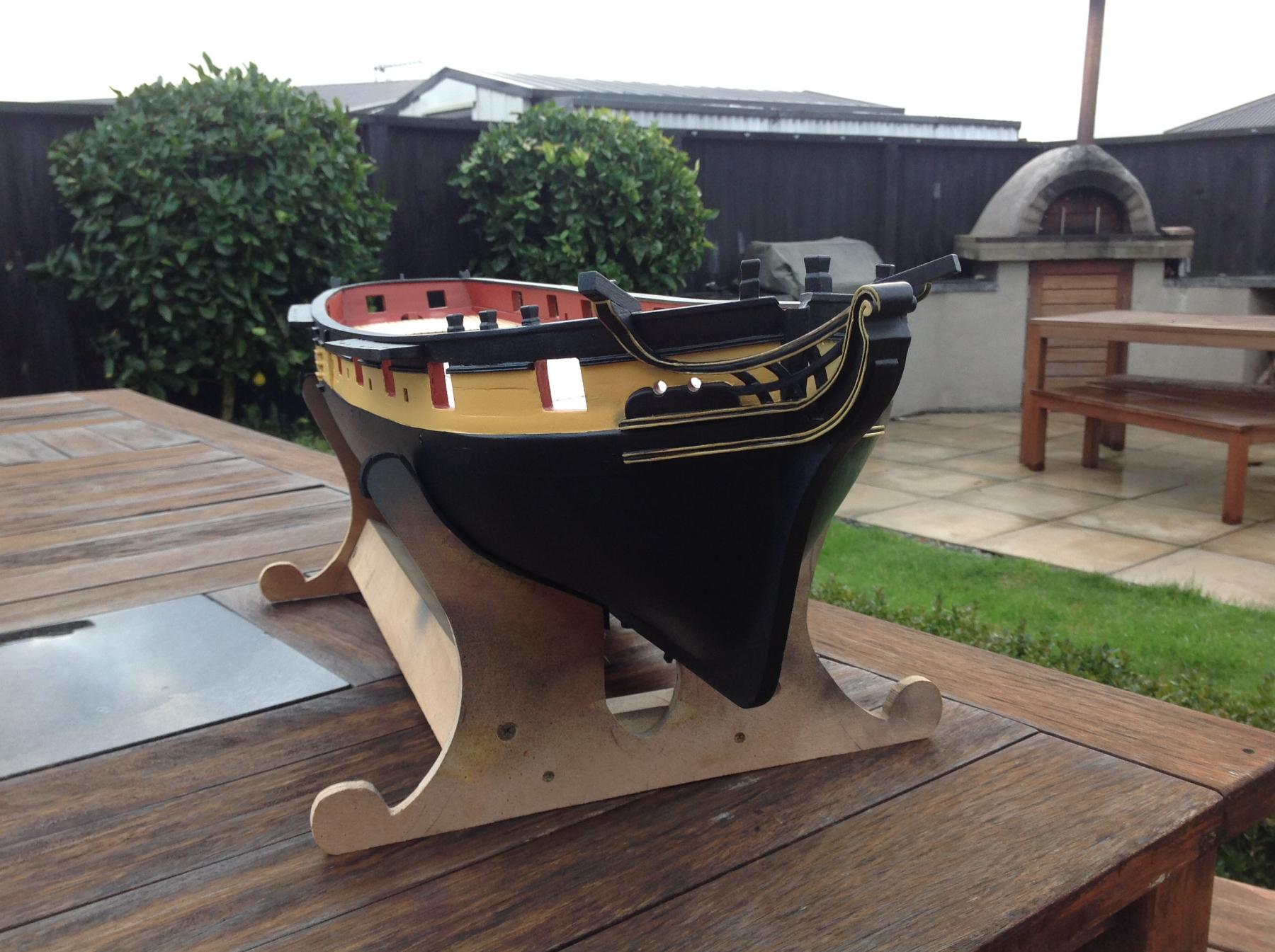
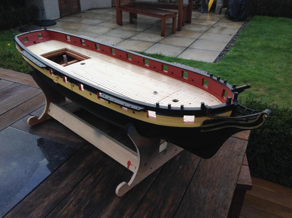
Another day of masking, spraying and finally touch ups by brush and the exterior paintwork is largely finished. It's just some overstay on the red ochre and gunports to finish. I'm faily happy with the result.

- 141 replies
-
- 18
-

-
Hi john, Nice project. What's the size of the model? Although it's cheaper here in NZ depending on quality the timber price sounds reasonably fair given postage to the US and it'll probably be a nice clean piece. It's ironic that I have bought timber for boatbuilding from the US and here you are importing something that seems relatively common to me. I guess we always want some thing exotic. Like most nz native timbers Totara is protected and can't be felled commercially anymore as vast tracts of it were on the way to disappearing before it was stopped a few decades back. Totara available now is either recycled from previous use ( there's still a lot of fence posts out there made from this lovely dense timber) or single trees from private stands. Let me know if you need any reference pics of waka. A fleet of probably the most impressive in the country are based not far from me and are brought out for a big annual regatta. They are quite a sight when on the river. The newspaper I work for has pics on file that while showing them manned and in the water should also show some carving detail. I could send some if it's any help. Wayne
-
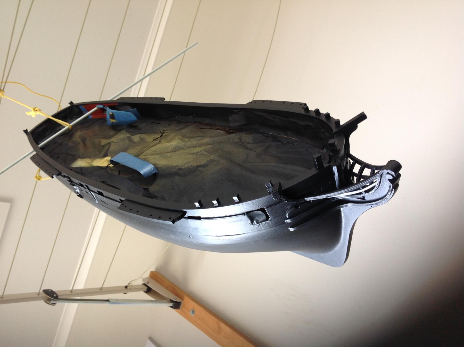
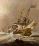
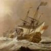
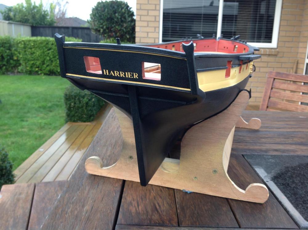
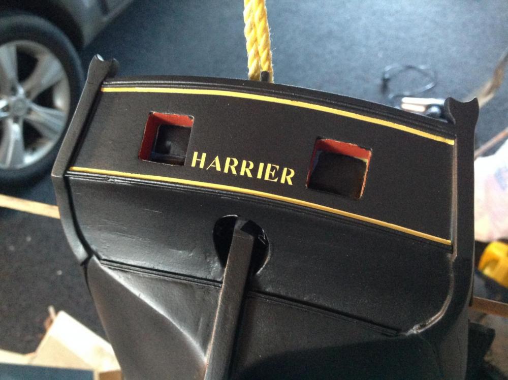
The main paint work has been applied. Yellow went on first, followed by a day's worth of masking and then the black. I'm using a brand called ironlaq which looks to be aimed at the crowd painting on the side of railway boxcars in the dead of night but it's quite good. I ran out of the black and had to use a rust-oleum black which takes much longer to dry and harden. A downside of a yellow boat was that it was easy to miss masking bits with yellow tamiya tape. Lots of spot touch ups to be done yet, especially on the head rails. I'm not showing the finished version until I'm happy with those. But in the meantime. Here's the stern, just in need of some touch ups on the lettering as it looks like a deco font without the TImes Roman serifs ...... Yes her name is Harrier. She was an active little vessel, although fir built, and served a spell in home waters before being involved in operations in the East Indies. She foundered in the Indian Ocean in about 1809, I think, with the loss of all hands. May my Harrier not share her fate.

- 141 replies
-
- 11
-
-
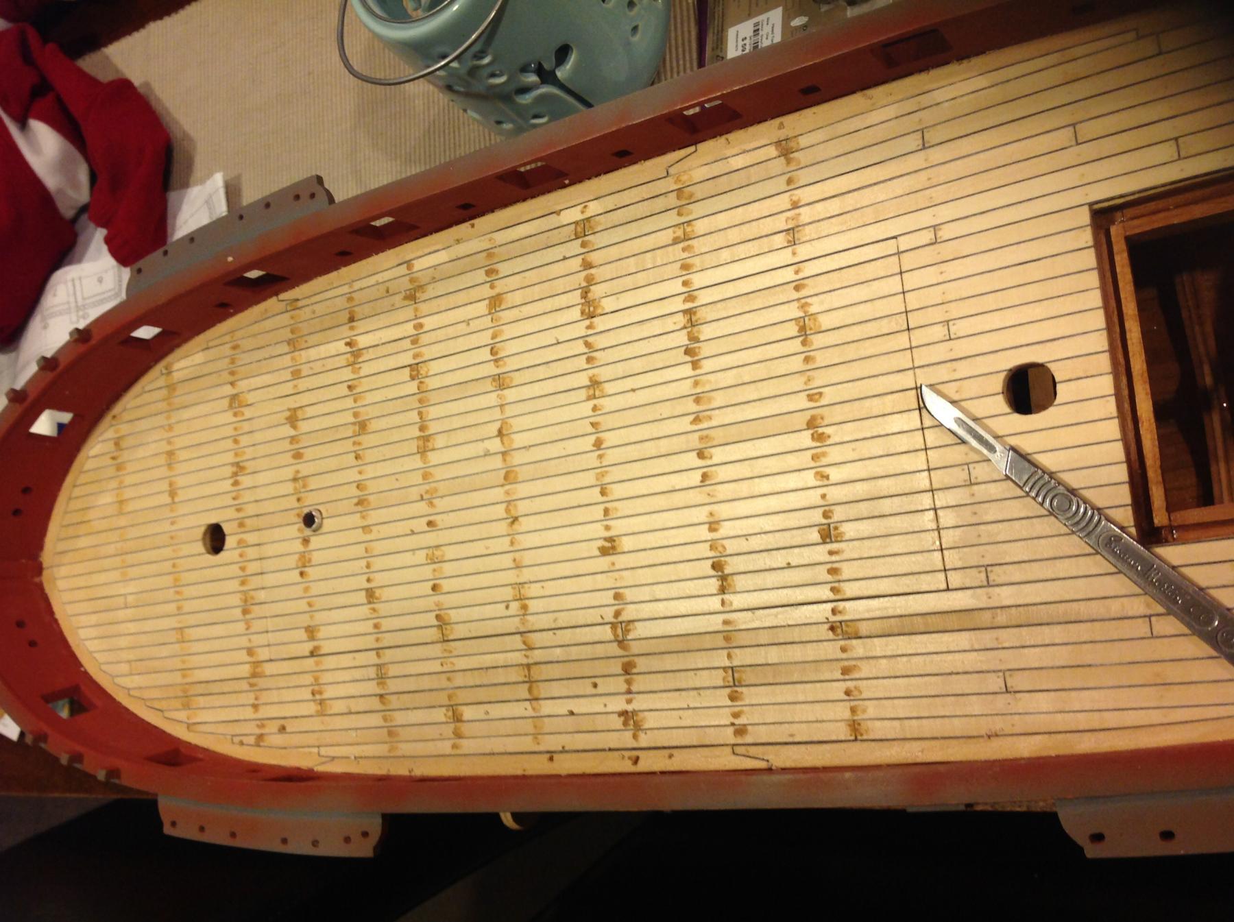
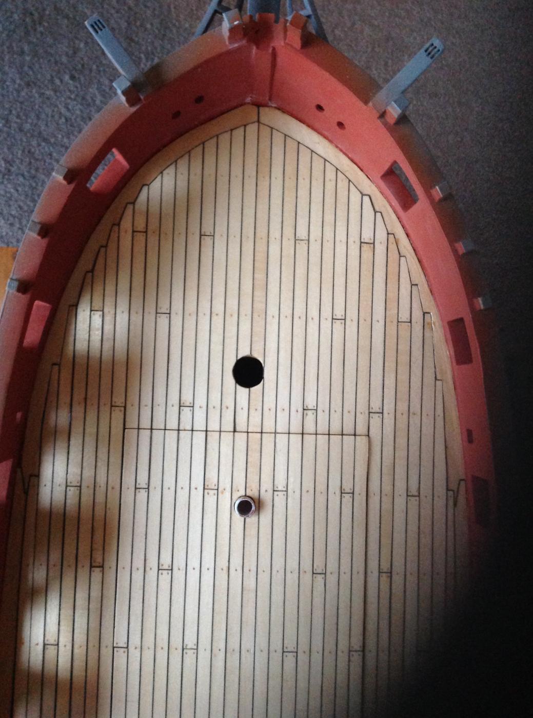
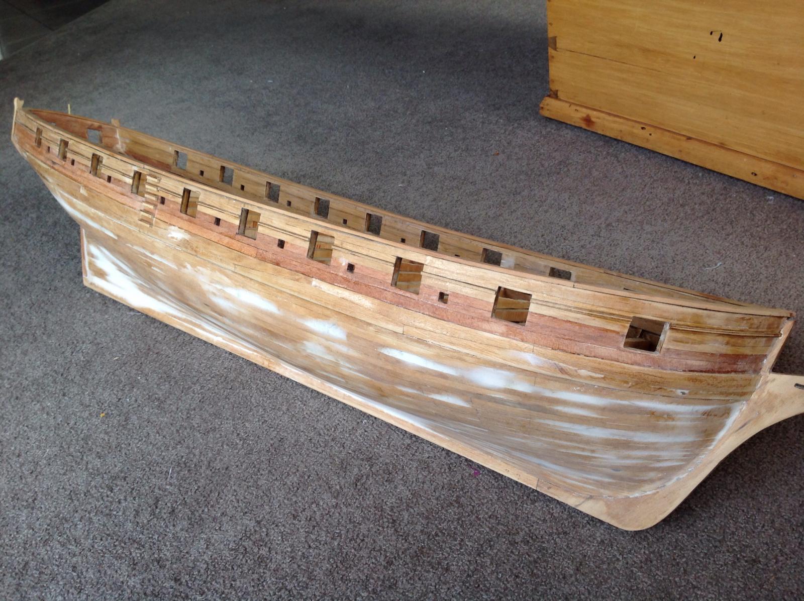
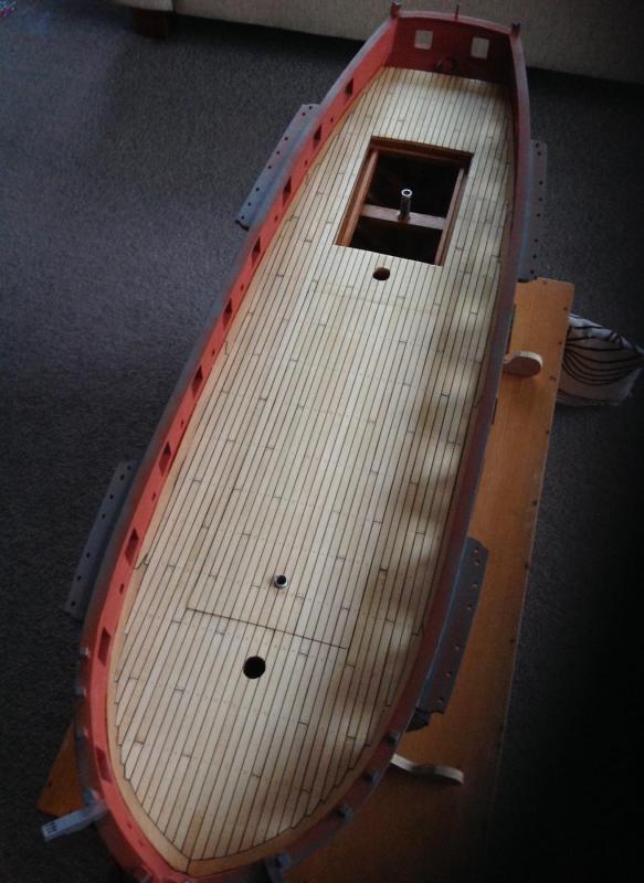
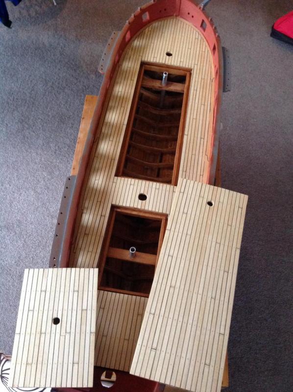
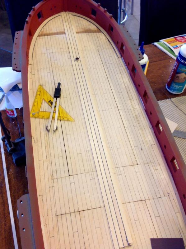
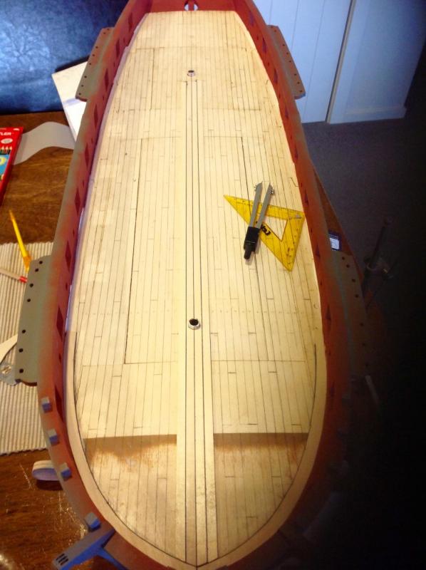
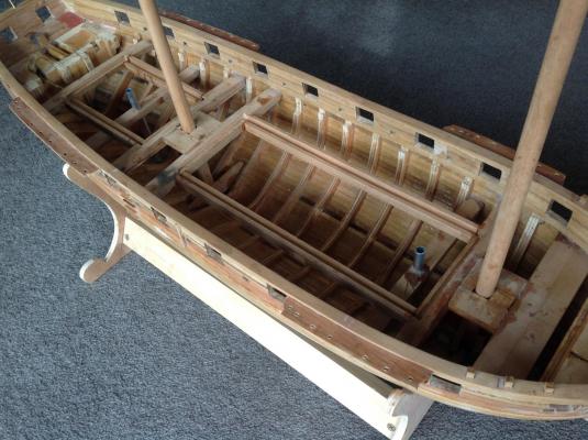
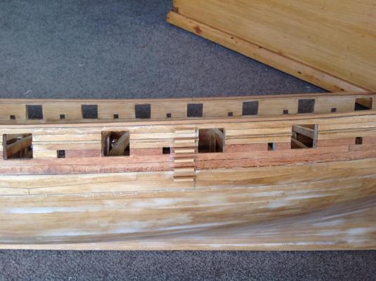
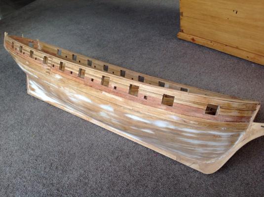
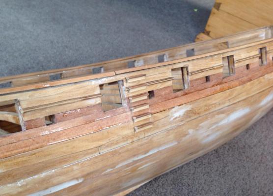
The deck is now finished. Treenails were done with holes drilled and filled with putty with the excess scraped off. I didn't want them to be overpowering so went with fairly small holes and a light coloured filler. They disappear from sight at a distance and certain angle and reappear when you change your view. It adds nice interest. The varnish has turned the grey card caulking blacker than I would have liked but waterproofed it all nicely. I'm happy with it. The join in the margin plank was a little too close to one of the plank nibs for aesthetic purposes but it'll be covered by a carronade so problem solved. Next task is adding the spirketting and scuppers and then the gratings.


- 141 replies
-
- 15
-
-
Yes, I'm enjoying the larger scale. It's a bit easier to add the detail but given the working nature of the model I'm not labouring total realism on everything. I hope I can go back to something smaller one day.
-
That's a handsome cutter with some great rig detail. Well done
- 269 replies
-
- 3
-
-
- Caldercraft
- First build
- (and 3 more)
-
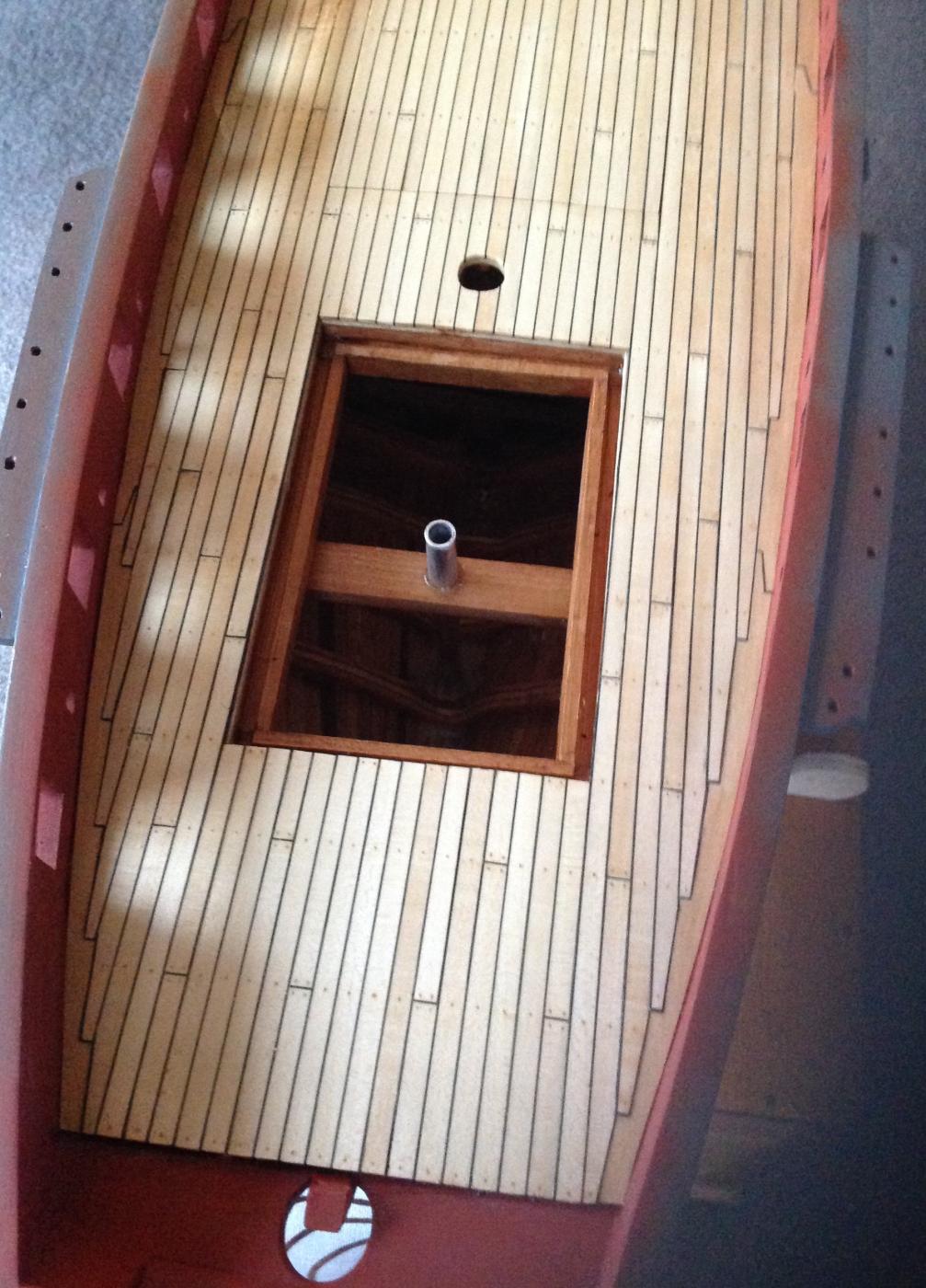
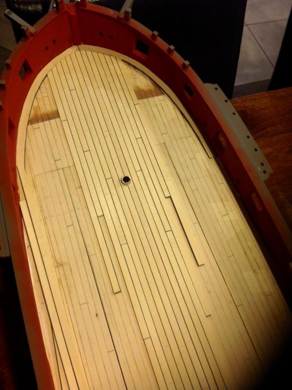
The false deck has been added with 2.5mm ply. This was done in sections and a hollow near the bow filled. The access hatches had their own ply covering and sit flush with the rest of the deck. The idea is they almost disappear when in place and planked. Planks are cut from a basswood sheet with dark grey card glued to one side. This gives a consistent line for caulking which is more of a scale colour than straight black. The wood is a bit soft but it'll have a solid covering of resin or varnish to protect it. The deck has been marked in the four butt shift pattern based on where the hatches and other deck furniture will be and the first planks laid on straight over the hatches. The hatch joints will be cut through once more planks are laid on and also mast holes recut. The central planks are laid full length as deck furniture placement means no plank joins would be visible. The margin plank was drawn on the deck and traced with the pattern transferred to a basswood sheet for cutting. Care was taken to achieve symmetry on these as at the bow as from plank 9 on either side they will be joggled into the margin plank. This pattern was drawn on the deck to make sure both sides lined up. Lots of repetitive planking ahead but it feels rewarding.
- 141 replies
-
- 12
-
-
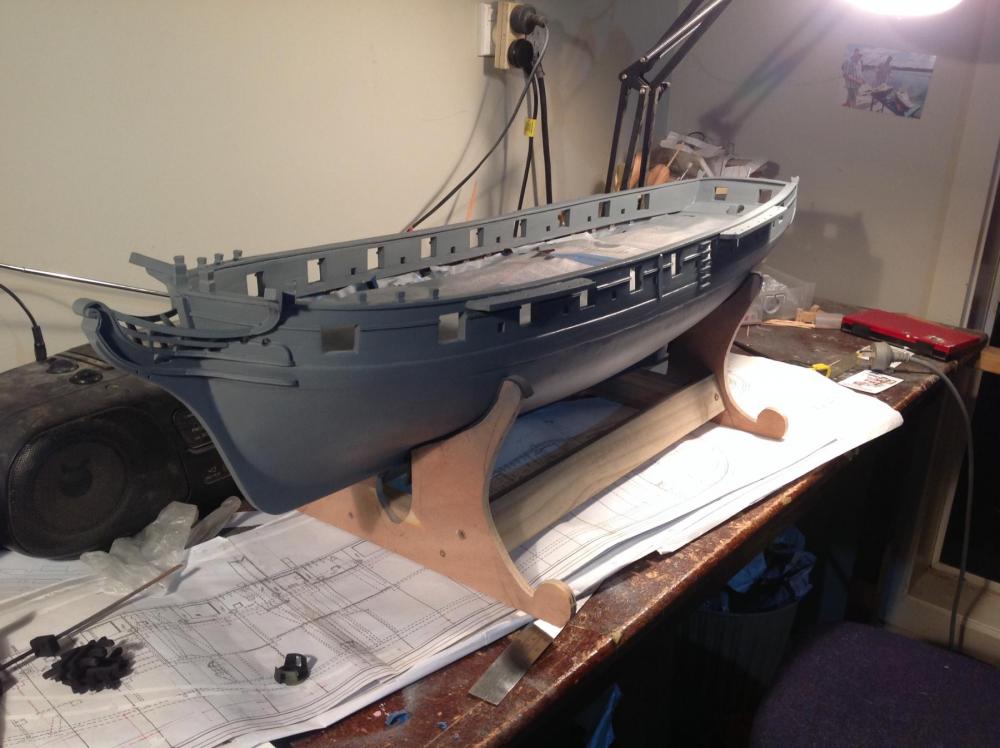
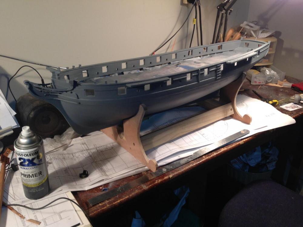
A coat of primer has been sprayed on and the major imperfections filled. Main coat of nelson's yellow on black awaits. The masts are presently varnished timber with black. I think I'll leave them like that as a nod to the fact the boat is not plastic. Mast rings etc to come.
- 141 replies
-
- 22
-
-
Thanks bob, I'm sure I obtained the idea from someone else as there are very few original ideas out there. It'll have a rubber sealing strip and some arrangement to secure them down snugly. I'm hoping to apply some paint soon which will make it look very different.
-
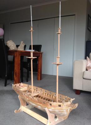
Thanks Steven, The height from keel to the mainmast tip is about 1100mm. The vessel does fit in the back of the wagon when on a lean. I thought while planning the project that it wouldn't without masts lowered but there you go. Even so with the top gallant and top masts lowered once the fids are removed it'll take at least 300mm more off so no problems on the transport front. When she finally gets on the water I've got plans to mount a go pro on her. Hopefully it won't be footage of a titanic-esq maiden voyage.
-
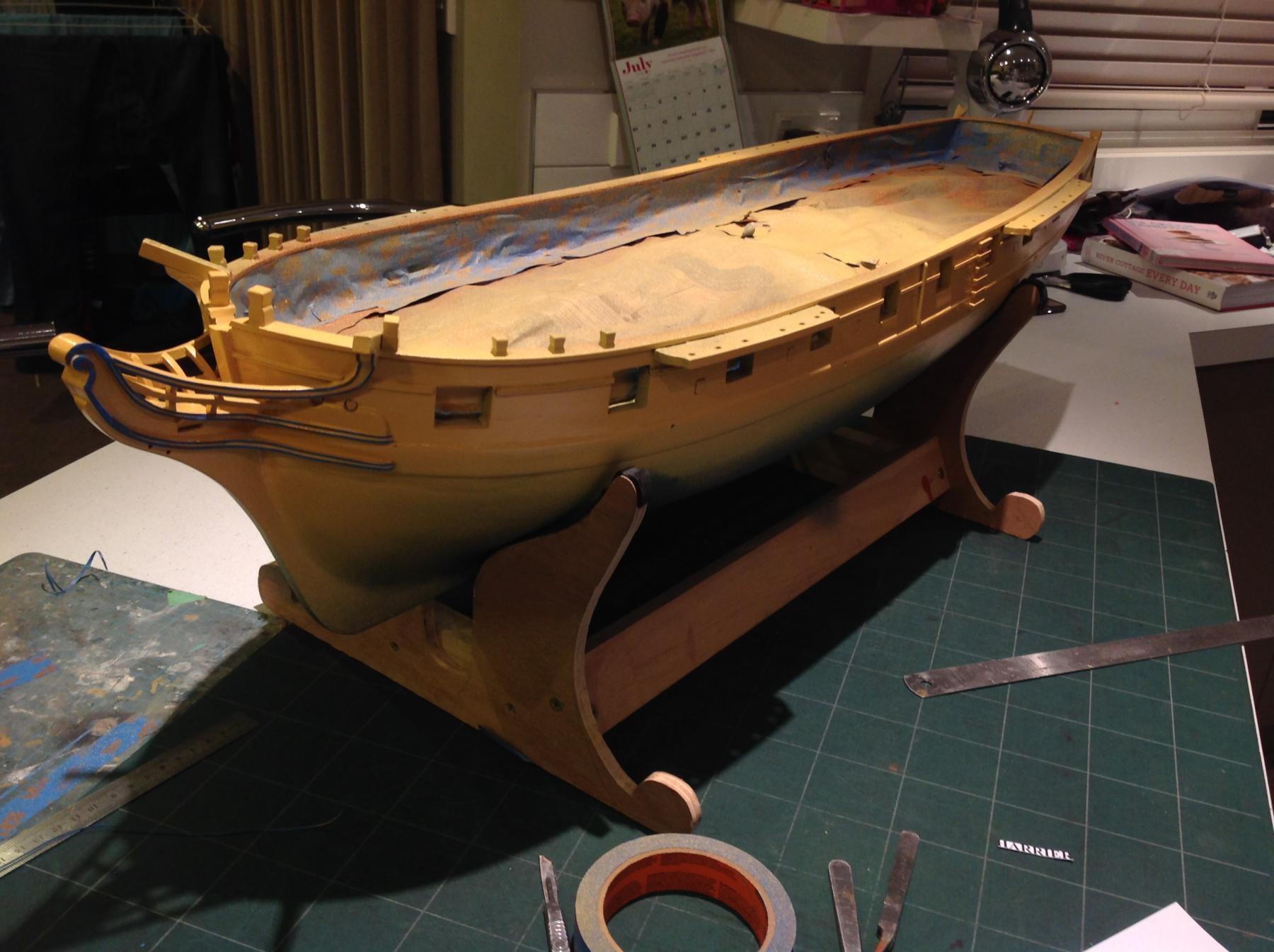
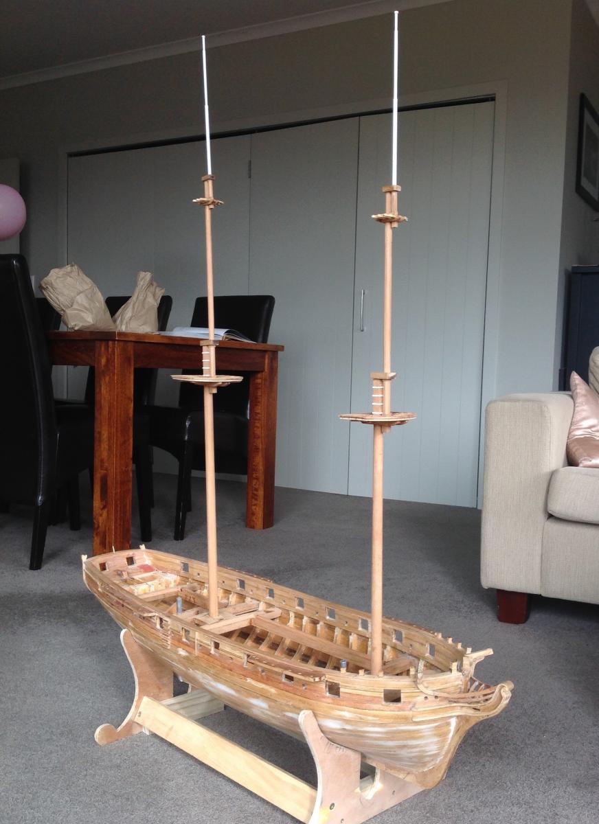
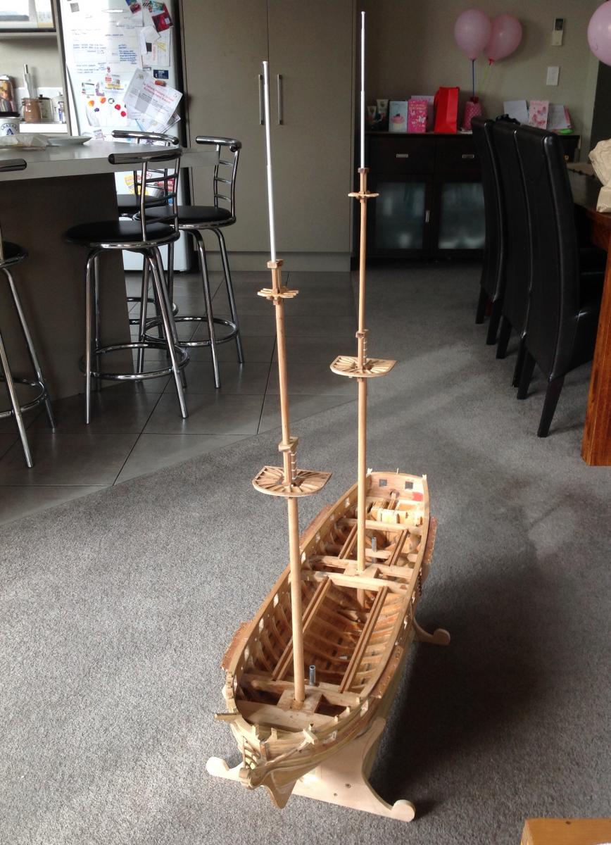
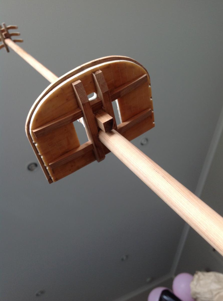
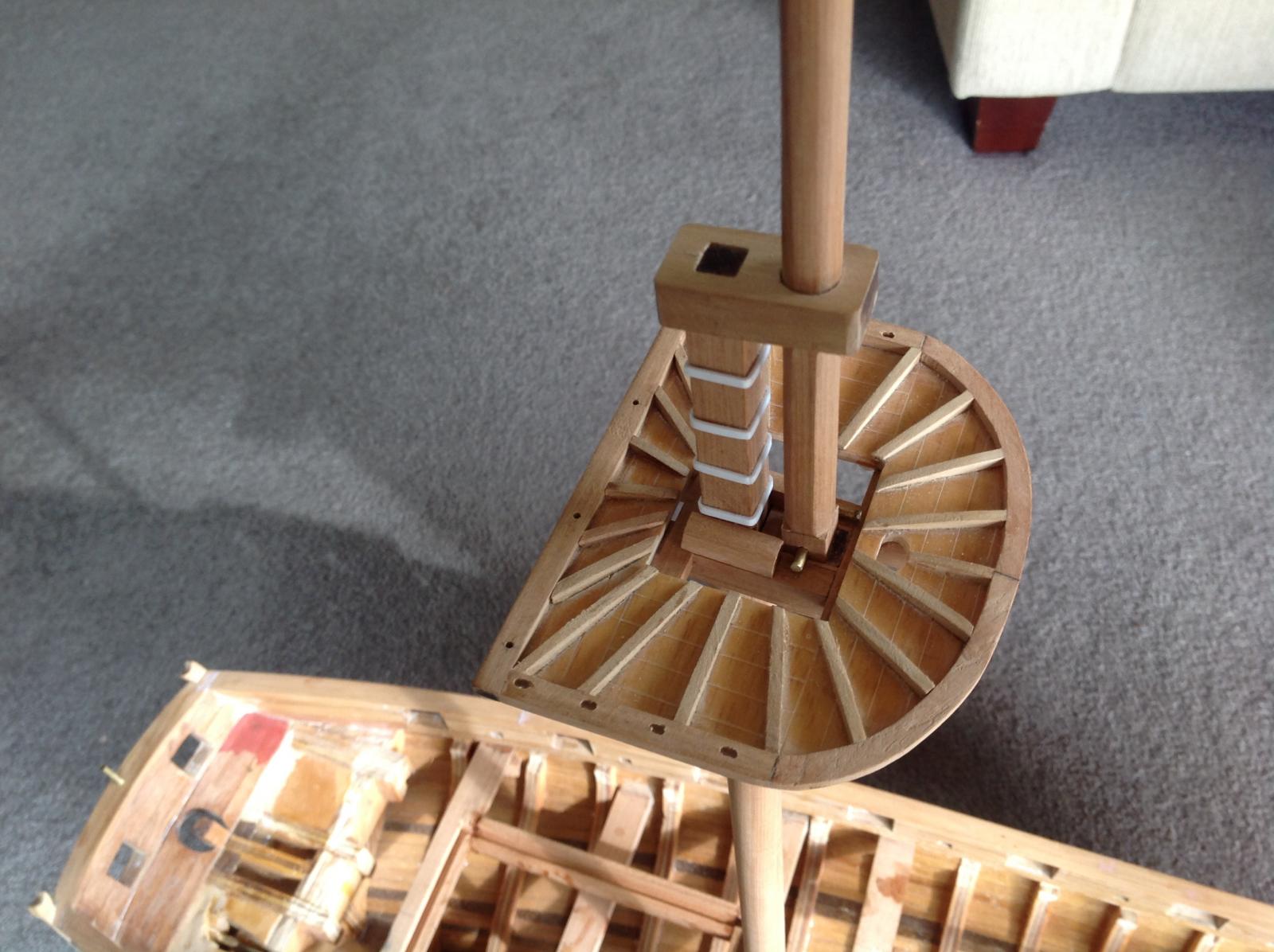
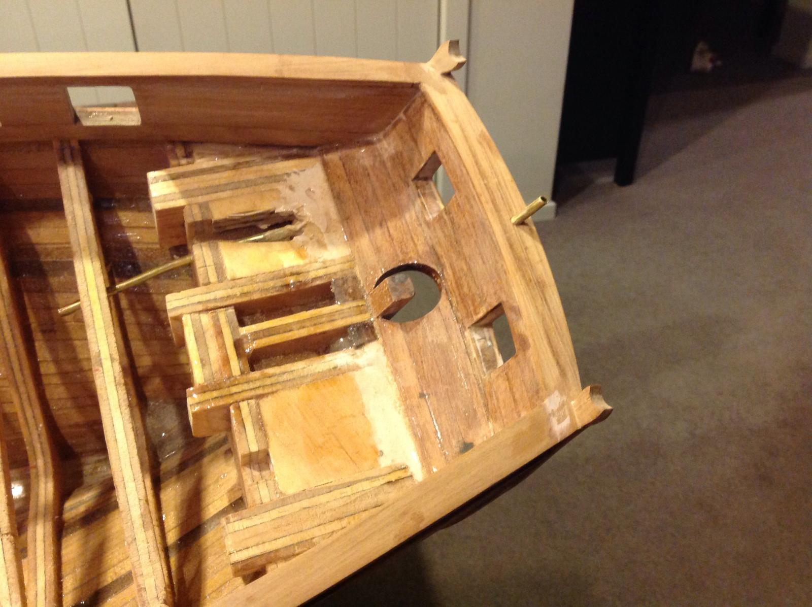
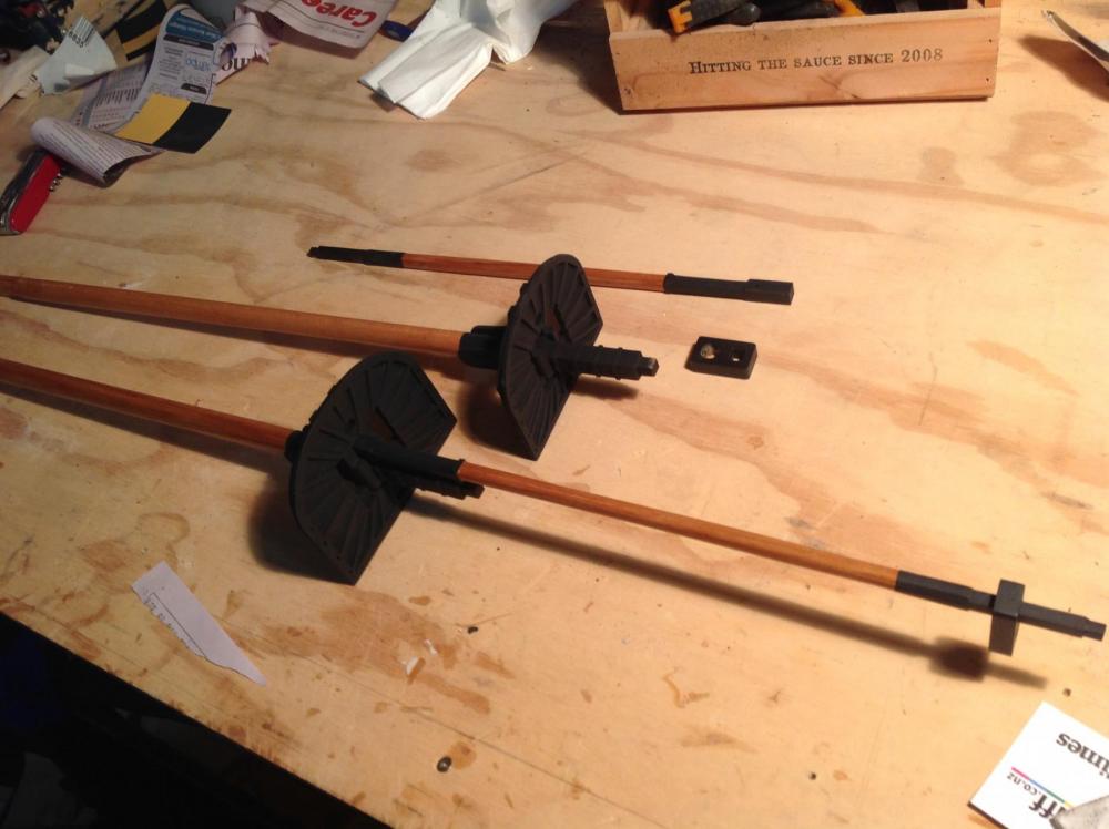
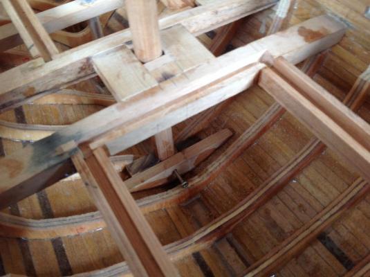
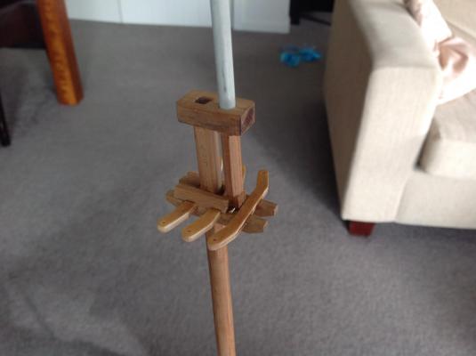
It has been a while but there has been some progress in the shipyard. With the hull largely complete attention has turned to the masts. These were again cut from matai and mainly shaped by hand with a small plane. With a diameter of 14-16mm and length of over 360mm for the lower masts they were a bit big for my small proxxon lathe. This was quite easy to do by hand and very satisfying. The top gallant masts were turned from fibreglass rod as wood would not have the strength at this scale and if anything will get damaged in transit it'll be the top masts and jib boom. The fighting tops were made from 3mm ply which was glassed on both sides for strength. These were up scaled slightly from petrejus' plans after reading about size differences among some forums of SC&H kits. The batons and trestle trees were cut with the Byrnes table saw which allowed some very close tolerances and ensure everything fits together very closely and is quite strong without being stuck together. Working fids will allow the masts to drop down for transport although a test fitting has surprisingly revealed the vessel fits (with a list) in the back of the family SUV. The hounds are yet to be added but won't take long. The masts have been stepped in boxing with the help of their square bases and secured with a wood screw so if disaster strikes it's all remove able. It isn't pretty but practical. Also the rebated frames of the access hatches have been added, giving a final indication of how much room there will be to get at the mechanical entrails - hopefully it'll be enough but I'll aim to have that planned out and largely installed before the majority of the decking goes on.


- 141 replies
-
- 22
-
-
Looking very good indeed Jason. I'm wondering why you bought the kit now this is heading into scratch build territory with such good results.
-
That's a classy case that finishes Granado off nicely Joe. Great work.
-
Thanks Jason, yes the scale is quite nice for detail. It's big enough to add the bits you like and still fudge the bits that are too difficult. The moulded effect was cut with a scraper cut and filed with a profile and an overhanging edge that could be run along one edge of the timber so it scraped a groove at a consistent distance. Small files and blades were used to define it further. The timber is a little too soft and my technique not good enough to get a super crisp edge but I'll be looking for painting to further define it.
-
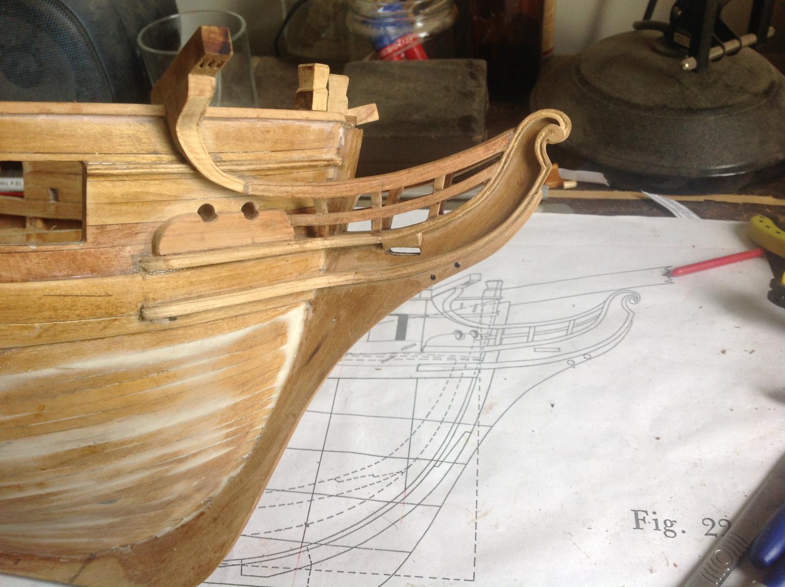
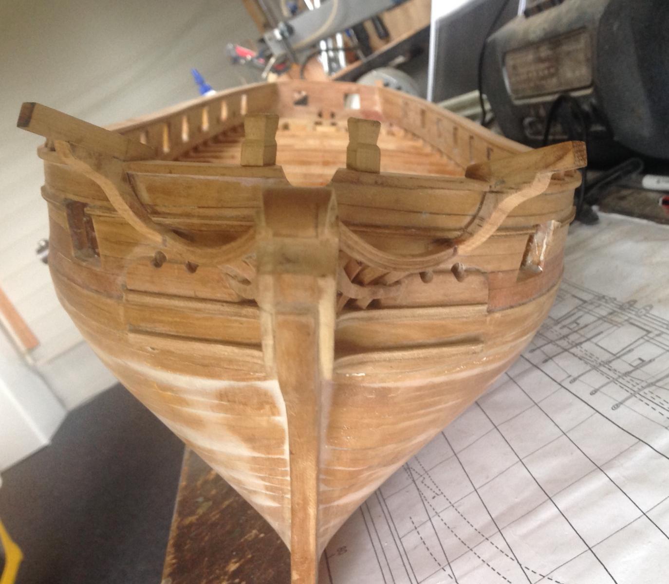
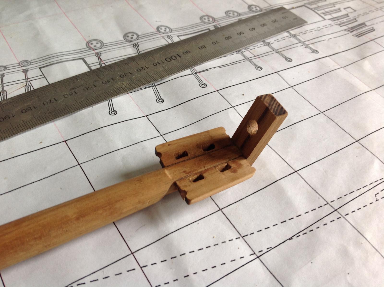
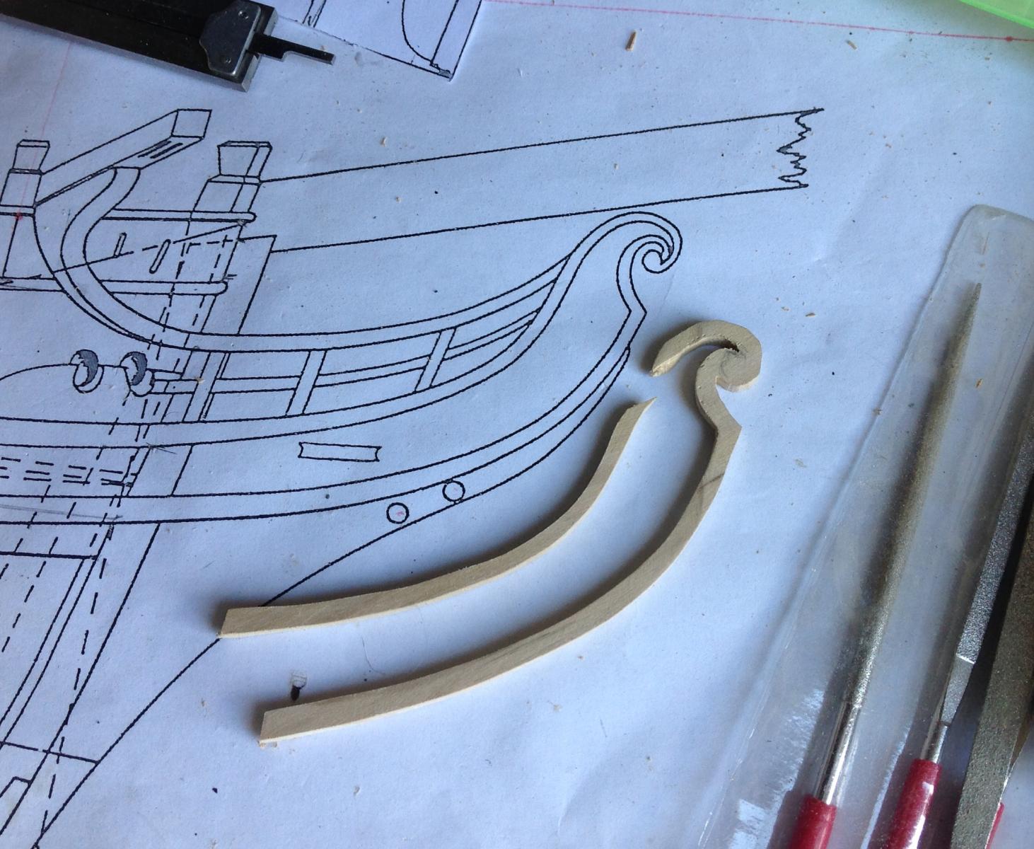
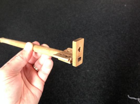
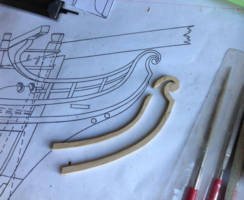
Some decent progress on the Cruiser over the Christmas/new year period with the bow largely completed with the addition of head rails and hair brackets etc. This makes her look like a proper ship. The process was started with cheeks, followed by determining positions for the catheads and hawse holes and bolsters. The catheads have slots and holes cut for anchor lifting blocks and are also pinned in place with a brass rod through each. The cathead knees were cut with the help of paper templates from a single block as per the effort on my granado build. Lots of trial and error to get them symmetrical and sitting right. The pic below makes it look like catheads are uneven and things are off but it's distortion of the iPad camera at close range. A brass strip with a moulded pattern filed out was scraped along the components for decorative edge moulding effect. The rails were cut from timber that had been fibreglassed on one side for strength. However, once the whole production is assembled it's surprisingly strong and should take a few knocks. I'll likely add a grating of some sort between the rail but am lacking any reference so will just cobble up something that looks right. A summer holiday awaits so that'll be it in the shipyard for a while. Next up are the channels, which I hope should be fairly simple. Then that's the hull pretty much done.

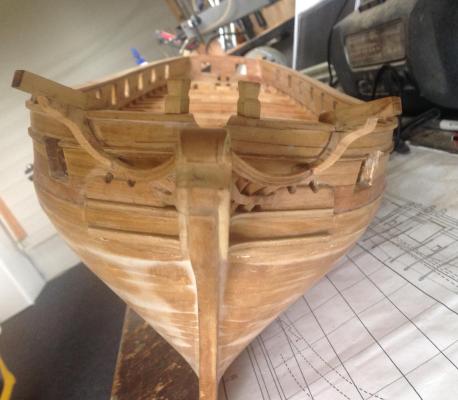
- 141 replies
-
- 19
-
-
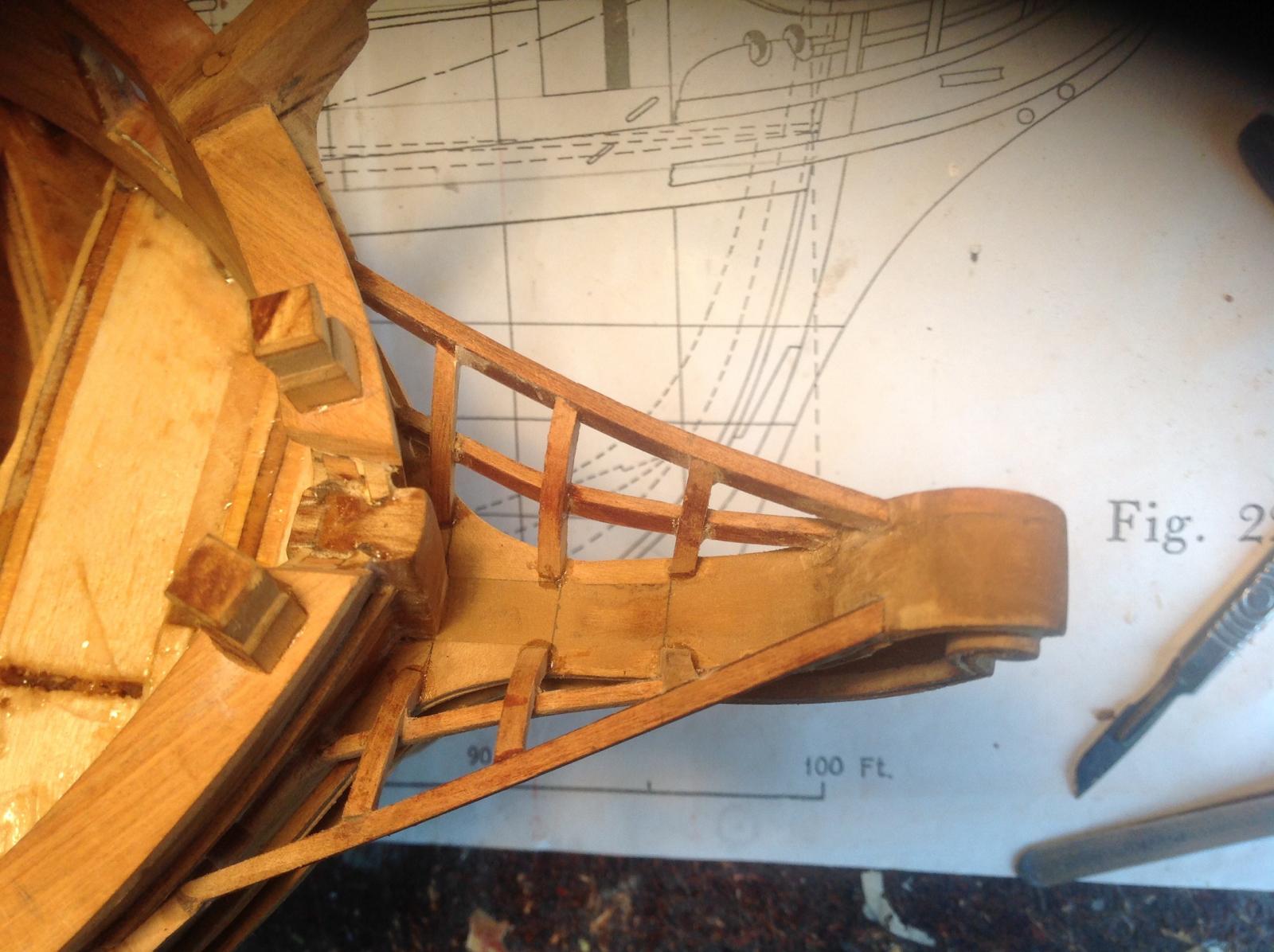
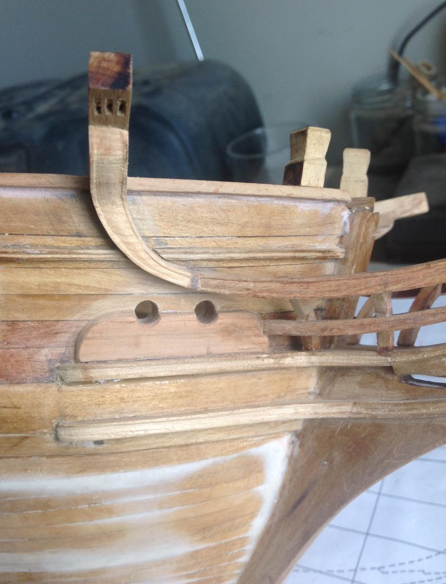
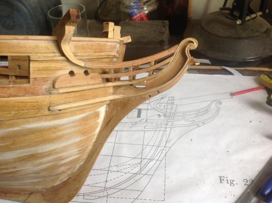
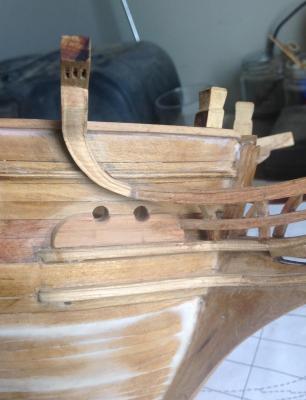
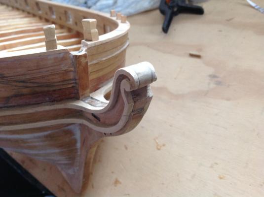
I've moved onto the head rails in order to complete the entire hull before moving on to the internal arrangement for the RC gear and ballast etc. The hair bracket for each side ( I think that's what it's called) was cut from a single piece of timber. It split on one side but this was easy rejoined and any gap will be filled later. Upper and lower cheeks have been added with templates for each cut from cardboard and a profile gauge used to get a good fit around the curve of the the bow. A scroll head was shaped into the brackets with a file. This was very quick and easy and adds a third dimension to the bow decoration. These rails will get a moulded profile scraped into them as per the hull side rail. The bowsprit has also been turned and had the bowsprit cap and bees added to the end. I've got some small brass sheaves that will be fitted to the bees later. I'll experiment with a piece of timber but I expect it'll be too fragile for the spar most likely to take knocks so fibreglass rod from the local fibreglass/ surfboard shop might be the answer, Next up is the catheads and their fiendishly complex knees and hawse holes with bolster.
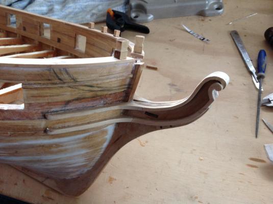

- 141 replies
-
- 19
-
-
Nice work there Mike. Your build looks great and you've sold me on getting g a milling machine when funds allow.
- 969 replies
-
- 4
-
-
- hahn
- oliver cromwell
- (and 1 more)
-
Hi Jason, yes it's Harrier but that's not confirmed as yet! There's plenty of options in 100 vessels in the class. The planking was spiled. Most of the planking lines have disappeared under the resin and paint is yet to come. I might rescribe the wale planking as it was so tortuous to do.
-
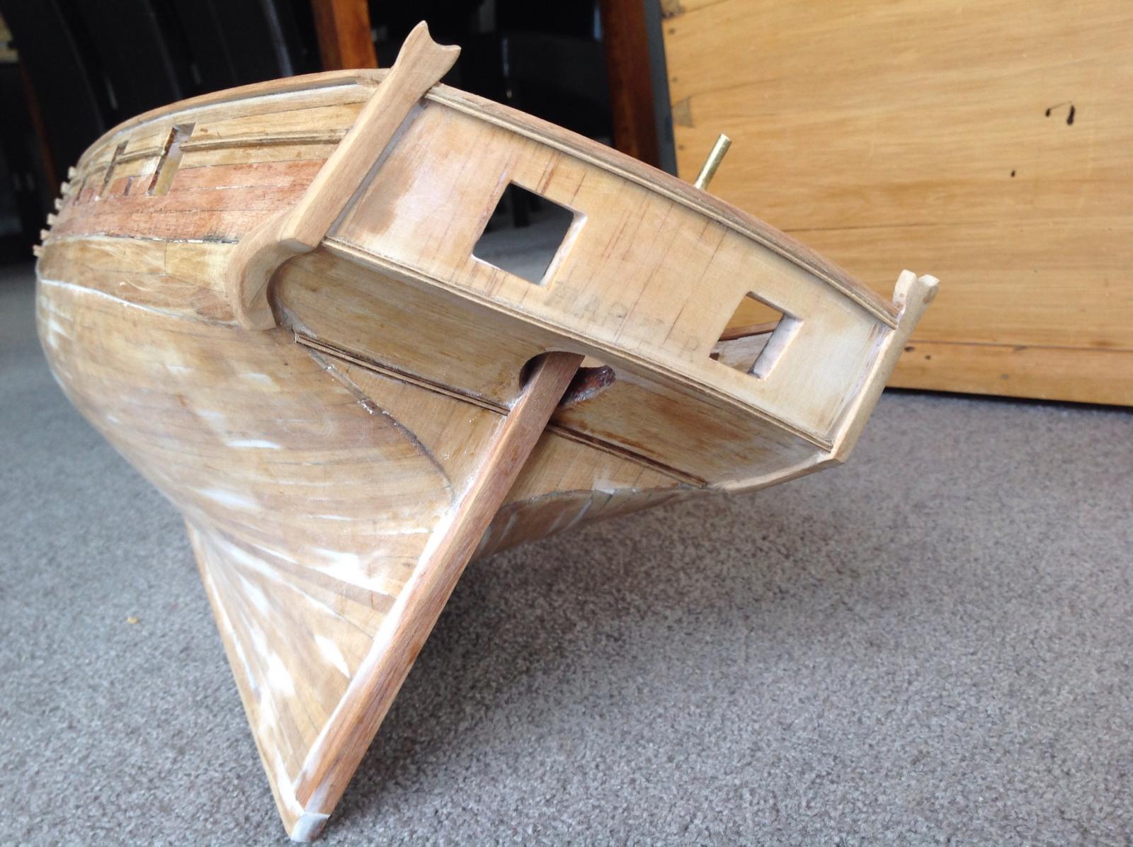
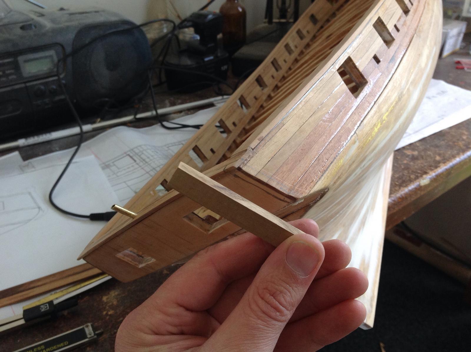
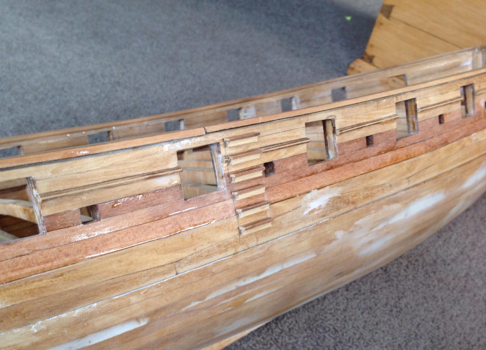
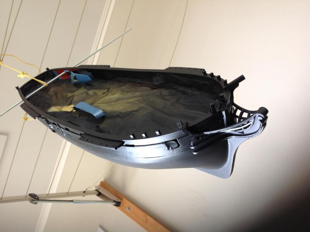
More hull work. The inside of the stern has been planked. And the capping rail added. This needs some filling still. Also on the stern the boom crutches have been added. These were shaped from a single piece on each side and a slot cut in the corner of the stern to recess it in. Once in place the fashion pieces were added with 1.5-2mm timber cut to match the curve on the rear counter side and another piece on the hull side. The seam between them was filled and sanded so it looks like one piece. I'm not skilled enough to cut this from a single pice to match the variety of curves in this piece. Also three lines of moulded strip were added at under the taffrail and faired in, at the bottom of the counter and lower down at the transom. A strip also runs the length of the hull. These were made with the shape filed into a razor blade as per Chuck and other luminaries on MSW. The entry steps had been added, these were made from two pieces- a moulded strip made as above and a flat plank step. Next it's either the head rails or strengthening the deck beams with cross members and marking out the access hatches. The later might require a bit of wrestling with the hull so it might be best to do that before the head rails are added.


- 141 replies
-
- 10
-