
Captain Slog
-
Posts
904 -
Joined
Content Type
Profiles
Forums
Gallery
Events
Everything posted by Captain Slog
-
 Hi Ken, it’s a Hakko FX-888D soldering station. I did swap out the standard conical tip to a 2C tip (2mm angled) which is good for heat transfer and access. A 1C would be helpful in some spots and will get one at some stage but 2C is a good all-rounder. It gets up to my soldering temp (380 C for my chosen solder) from cold in about 40 seconds and can maintain heat transfer during soldering and takes only a few seconds to get from my set standby 250C to 380C when ready to go again.
- 23 replies
-
- 3
-

-
- Mikasa
- Merit International
- (and 1 more)
-
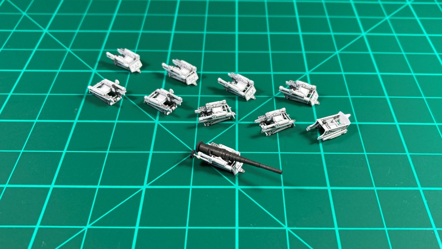
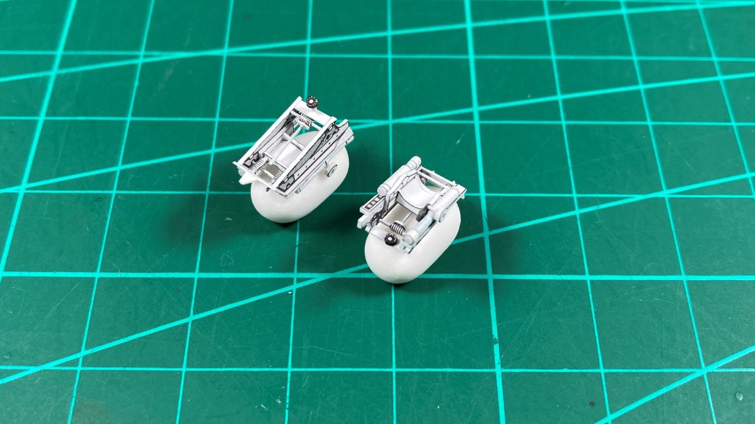
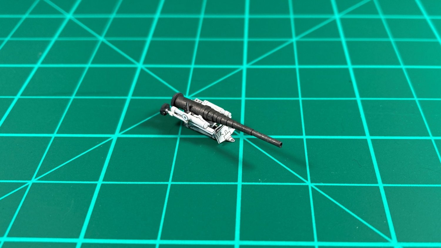
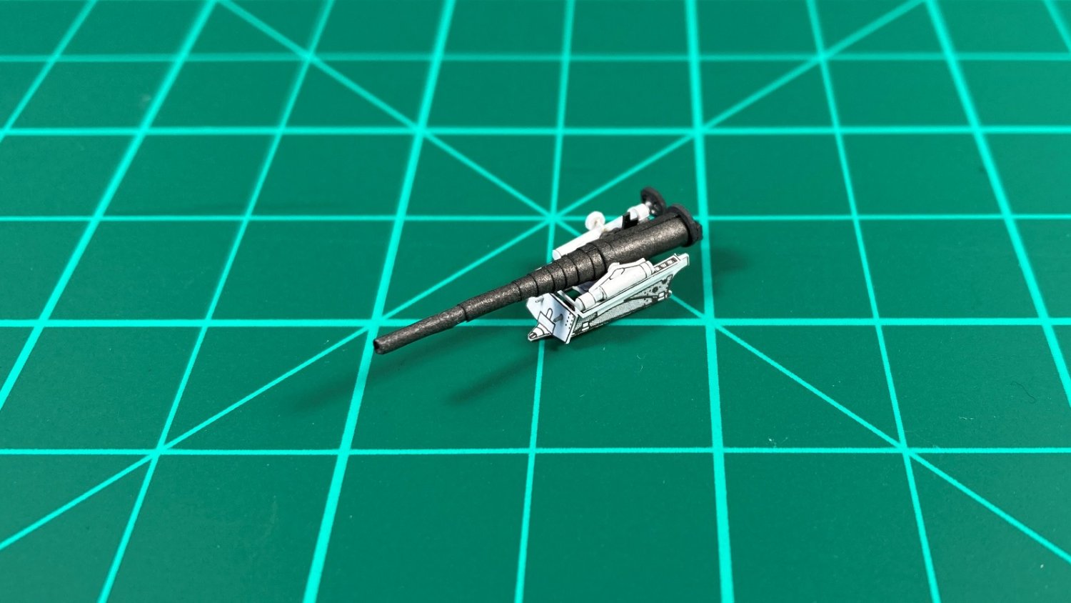
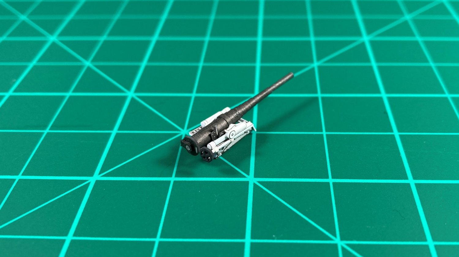
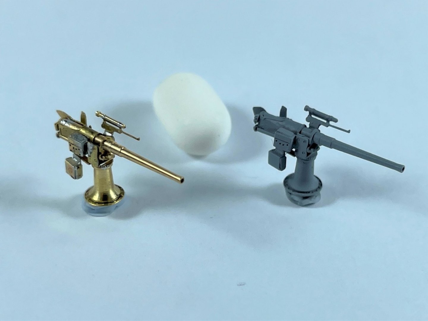
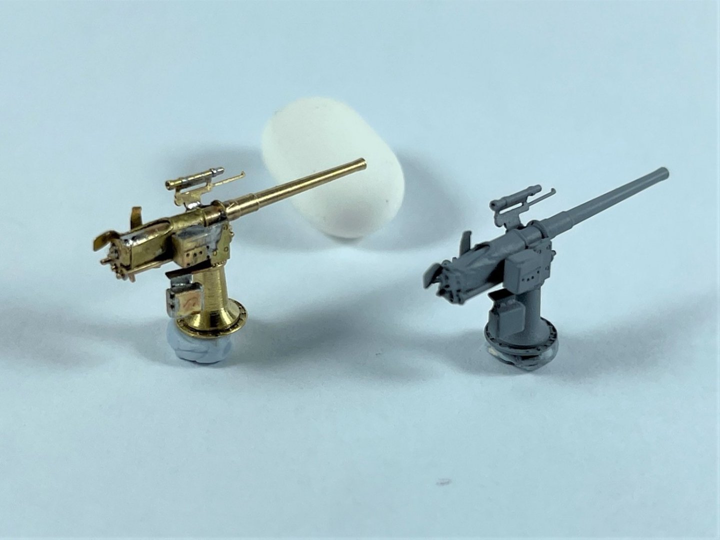
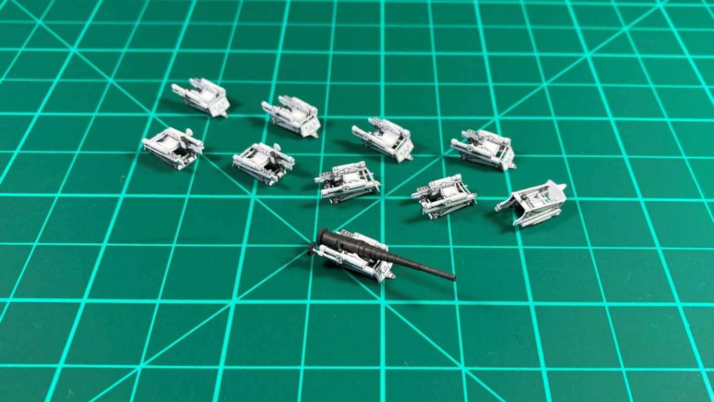
Hi all, I have been a bit slack in updating this log as progress is now up to Part 13 on YouTube but thought I would show what I have been working on for a future episode. I recently purchased a decent soldering station specifically for photo etch and have been using it successfully for items such as PE hatches but really wanted to push my abilities by using it on smaller multi-part assemblies. These are the Pontos 3” guns, which there are a total of 16 with 15 parts per gun and I completed 2 guns as a proof of concept to see if I can fully solder them which I managed to do. A few lessons learned in the order of assembly should make the subsequent ones quicker, easier and neater. The beauty for me over gluing, is that with small multi-part PE assemblies I usually end up knocking off previously glued parts when attaching new parts or sometimes just in handling. The soldering makes them very sturdy knowing they aren’t going to fall/break apart if dropped etc. Cheers Slog
- 23 replies
-
- 8
-
-

-
- Mikasa
- Merit International
- (and 1 more)
-
Hi, I'm no expert, currently working on my 1st plastic ship but will give my thoughts. I would be reluctant to keep sanding due to the amount of filler to remove but instead use a curved knife blade to scape the excess filler down to the original plastic again so as to have a fresh surface to start again. You don't mention what type of filler you used but I made sprue goo (plastic sprues dissolved with Tamiya Extra Thin, TET) and applied it very localised on the seam with a toothpick. Takes time to apply but quicker than sanding excess afterwards. The benefit of sprue goo is because it is made from TET it is 'hot' and melts into the seam line so that the seam doesn't keep reappearing again after final sanding. Then progressively sand down with finer and finer paper. I've attached the link below from my build log and if you scroll down to Part 4 you will see how I did the hull seam lines, which is in more detail in the Part 4 YouTube video linked there also. Cheers Slog
-
Scratch built chainplate
Captain Slog replied to RossR's topic in Metal Work, Soldering and Metal Fittings
Hi, I made chains out of wire and silver soldered them which was a first for me also. They were also blackened. It can be found in my Endevour build log which you would have to search for as it’s been many years since I updated it. cheers Slog -
So much life and activity going on! Outstanding!
- 200 replies
-
- 6
-
-
- Transport No. 103
- Hasegawa
- (and 4 more)
-
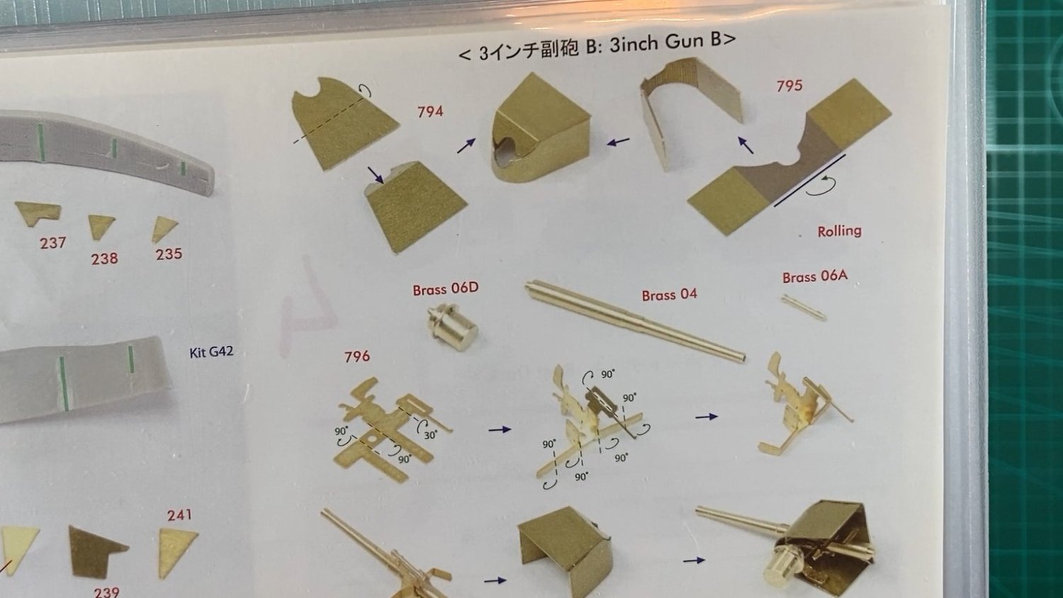
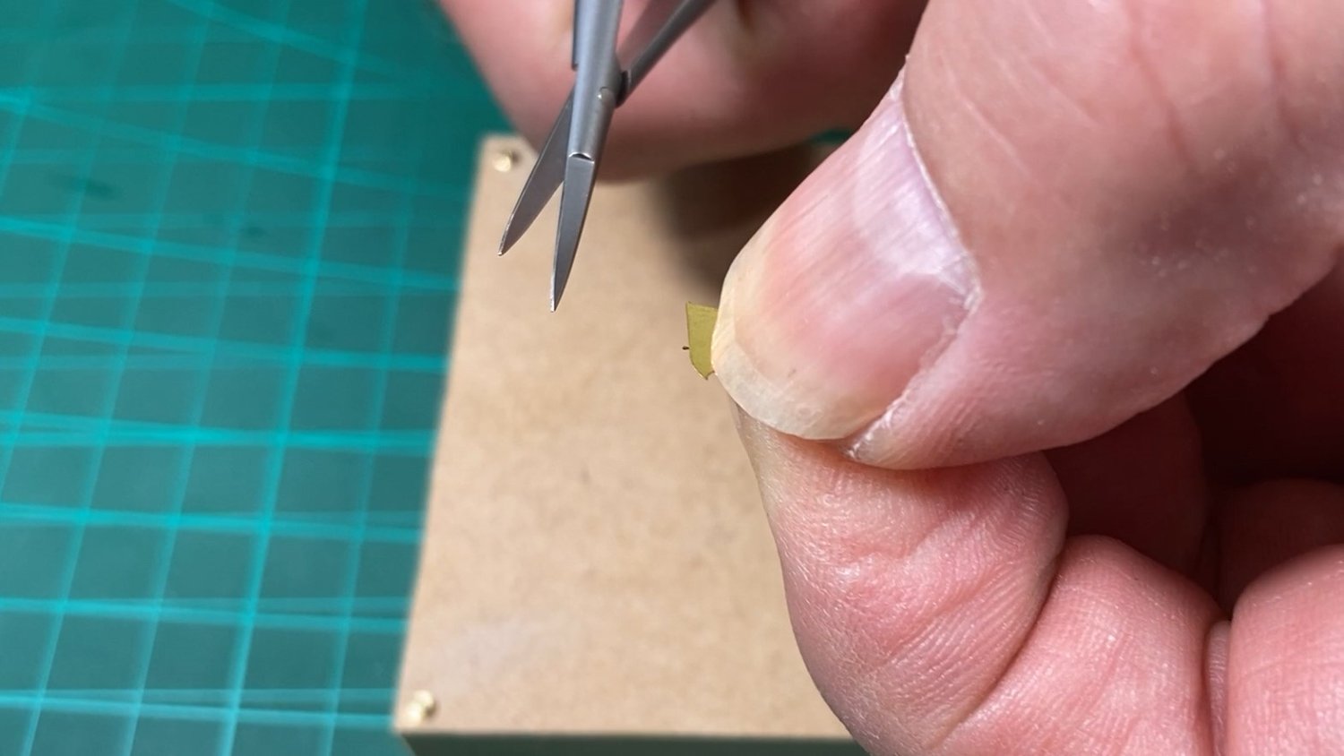
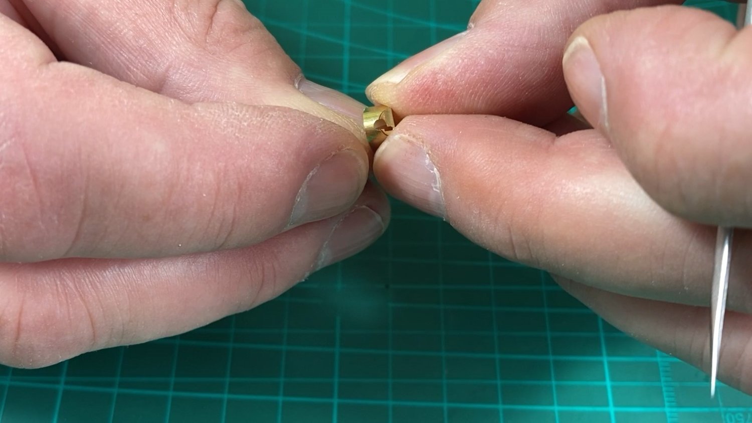
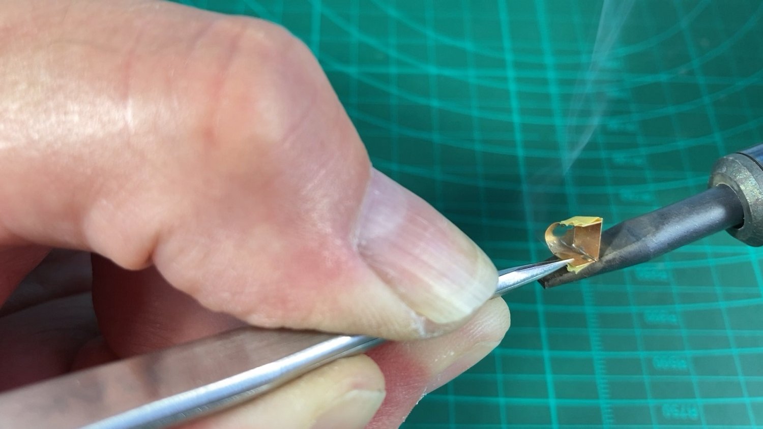
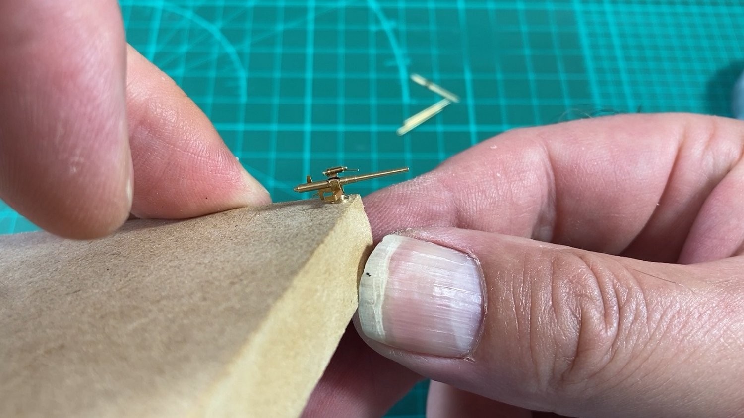
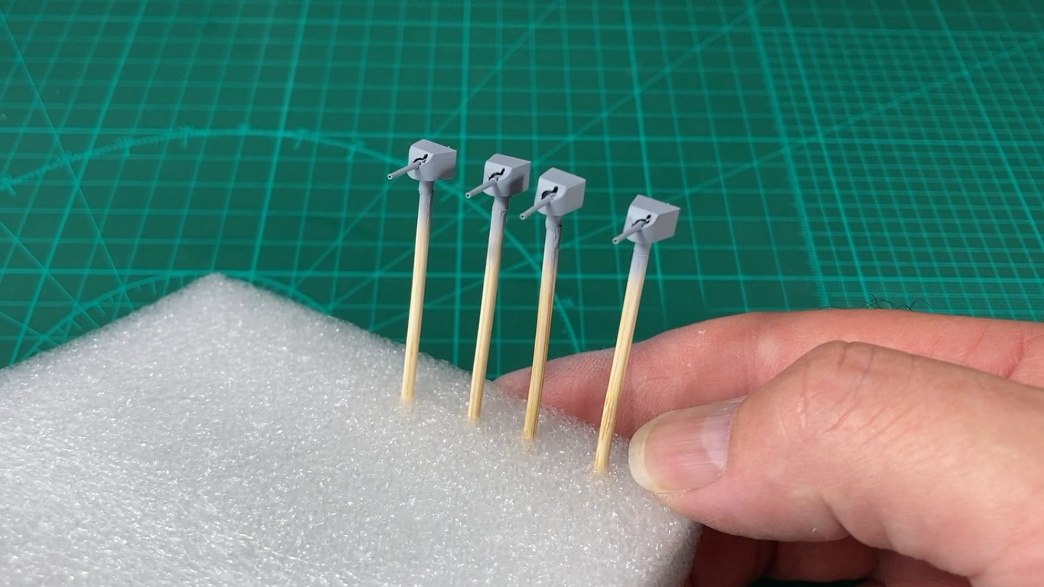
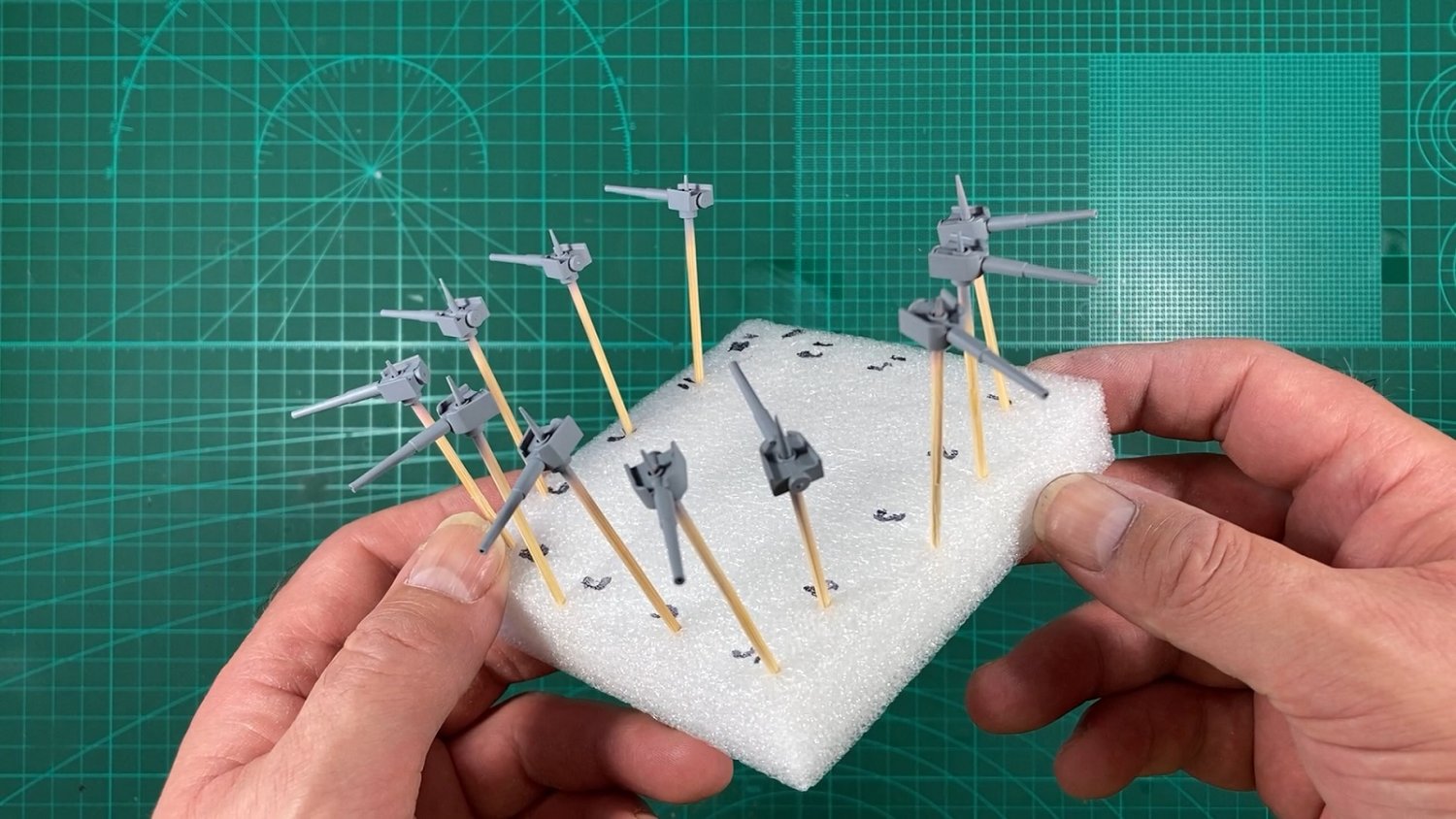
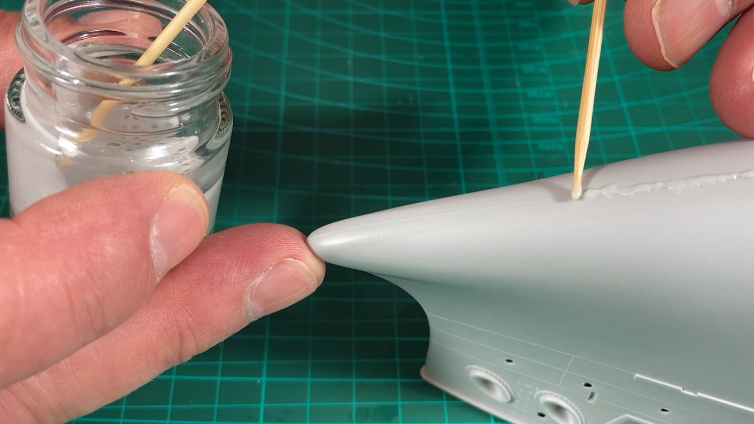
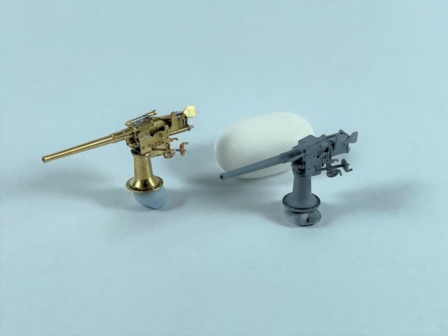
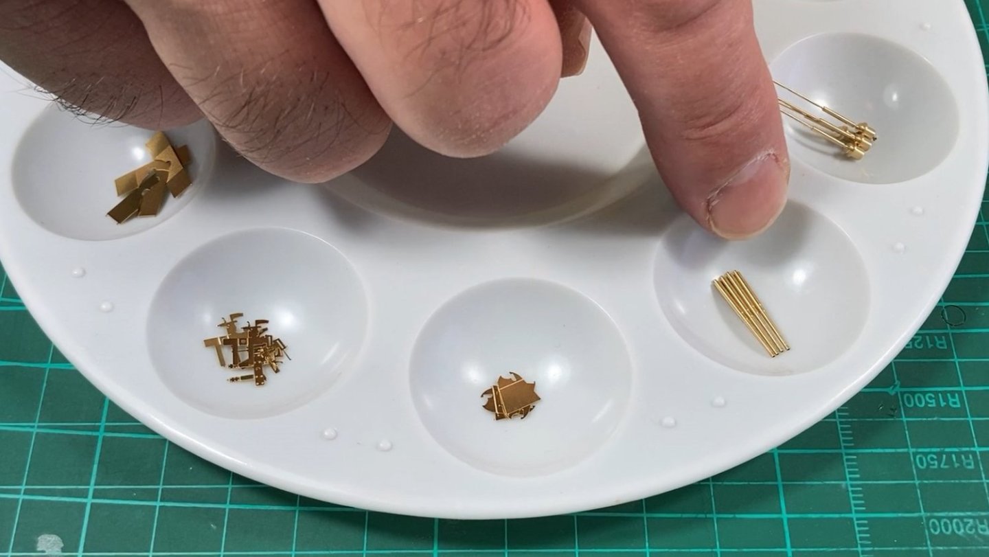
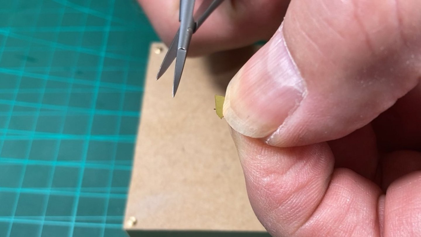
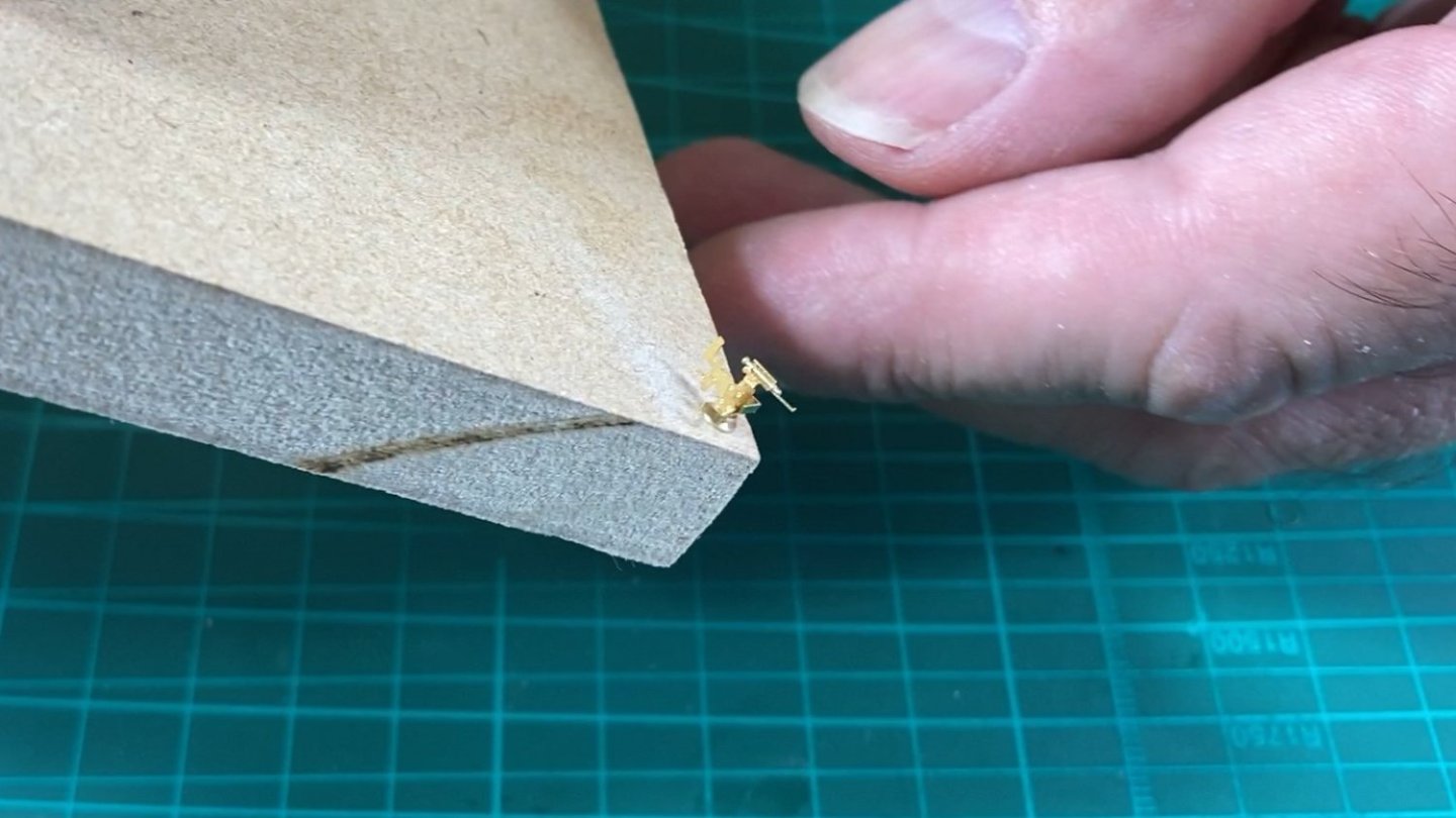
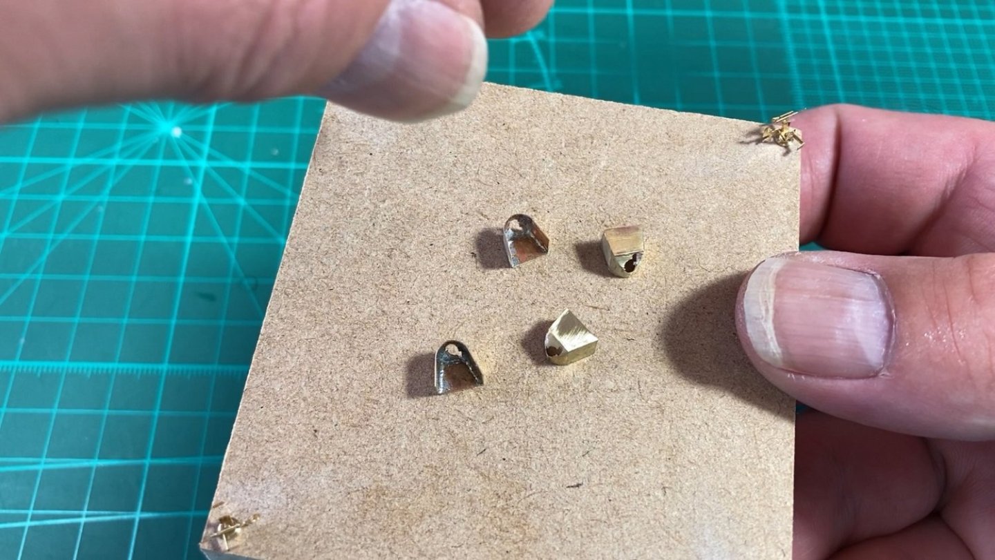
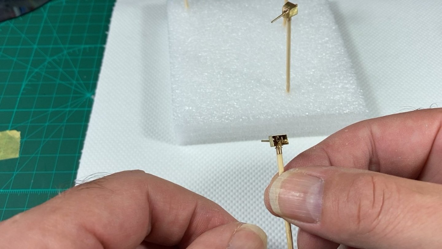
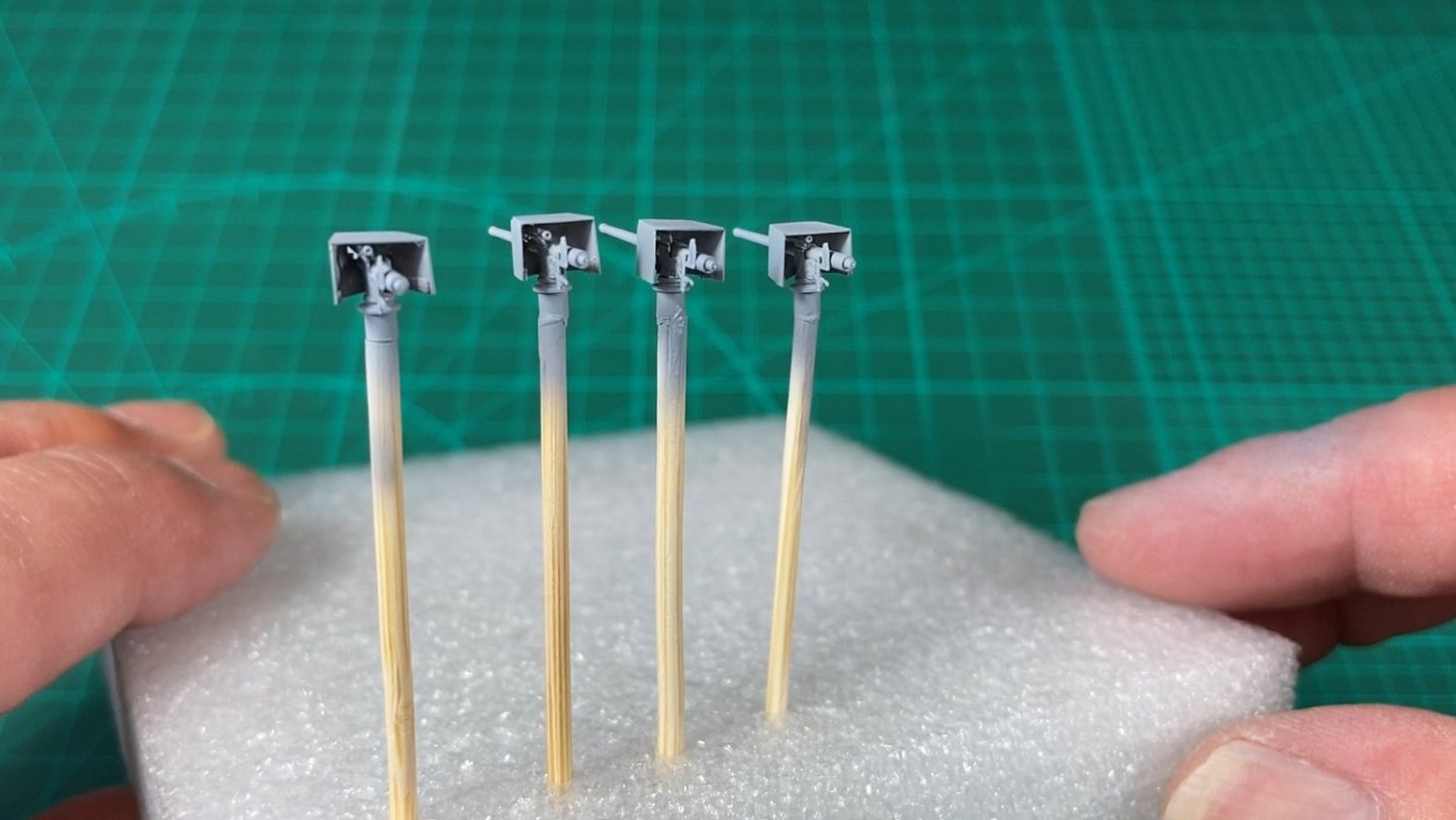
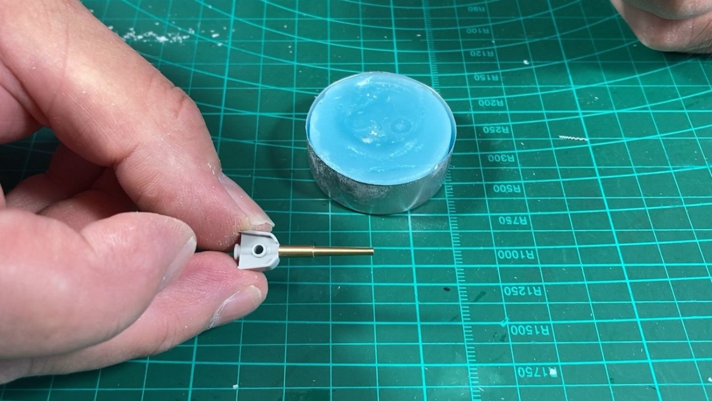
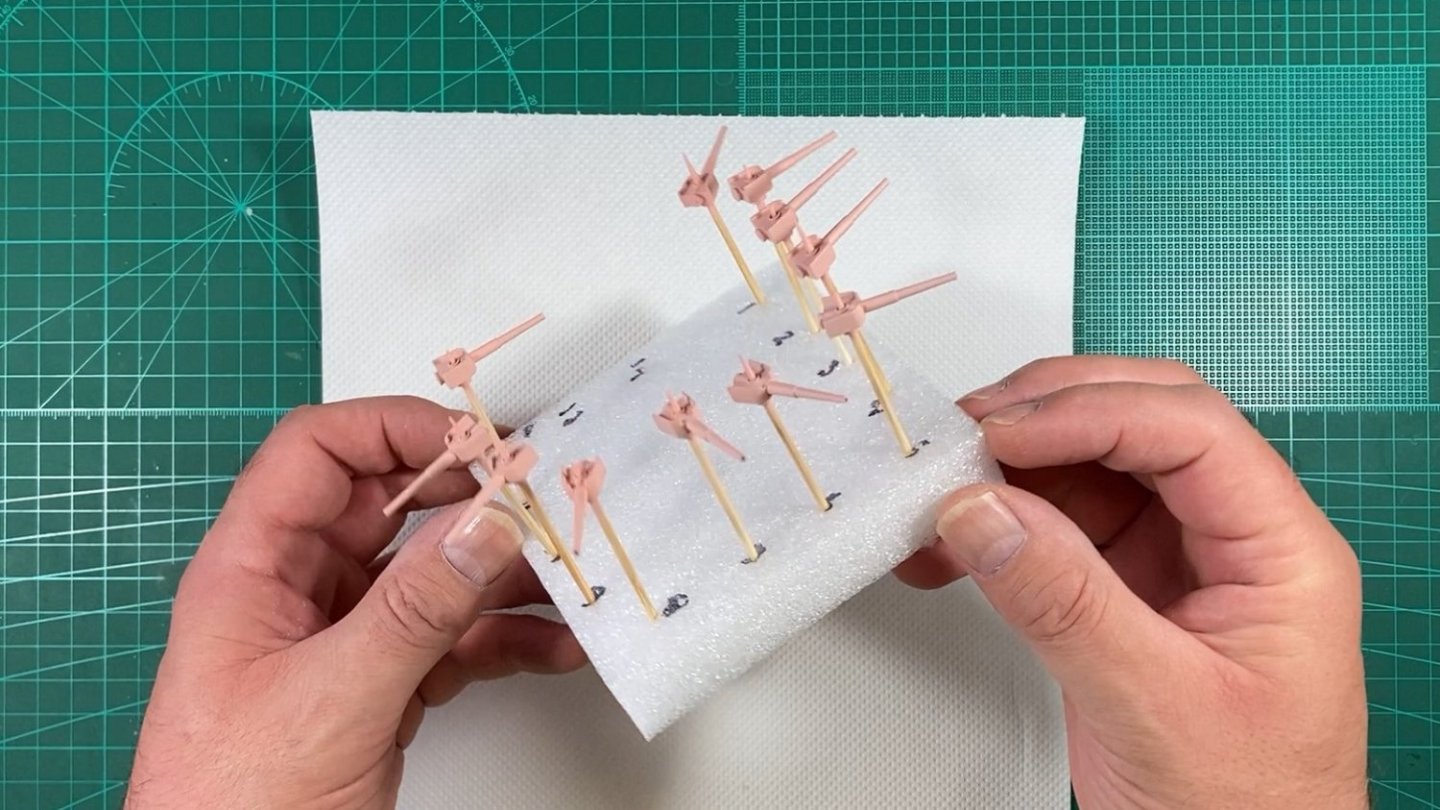
Hi, Here is Part 6. This covers 4 of the 20, 3” guns and replaces the kit part with Pontos PE and turned brass. These 4 guns are mounted in the bow and the stern and are simpler than the other 16 guns spread throughout the decks but do have a shield. There are only 6 parts, 3 PE and 3 turned brass. I like to use small PE scissors to remove the attachment nibs from the PE part and in the majority of cases there is no need to use a diamond file to clean up. I drilled a 2mm hole in the corners of a small MDF block to hold the turned brass pedestals so the guns could be built up around them. Photo shows the gun frame bent up and CA glued to the pedestal. The 2 parts of the shield were bent to shape and being trial fitted. I wanted to solder the shield together and used the method shown in a Paul Budzik (MSW member) video. The liquid flux is applied to the parts and small slivers of solder are placed in the joint. The soldering iron is held to the outside and the heat is quickly transferred through the thin PE. Due to the quickness I was able to do one side at a time without affecting the other previously soldered side. The 4 shields soldered and cleaned up. Didn't touch the insides as will never be seen and happy how first attempt turned out...some better than others. The barrel was super glued in place. The completed guns were CA glued to toothpick/cocktail sticks for painting. The bond is easily broken when time to install. The guns were primed with Mr Surfacer 1500 and then top coated with Tamiya lacquers. These guns are mostly hidden in the hull with barely the barrels sticking out. YouTube link Cheers Slog


- 23 replies
-
- 11
-
-
-
- Mikasa
- Merit International
- (and 1 more)
-
Hi Richmond, Enjoy your extra week! I agree, I was hoping to be further along also, at least have the main decks glued in placed! My baseboard is 200mm wide and with the hull being 124mm (according to the box) I should be able to 'lay' it on it's side (with suitable rolled up protection) if need be.
- 23 replies
-
- 2
-
-
- Mikasa
- Merit International
- (and 1 more)
-
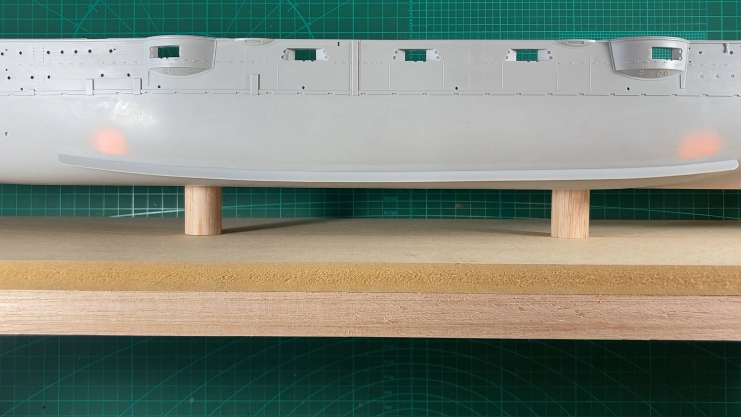
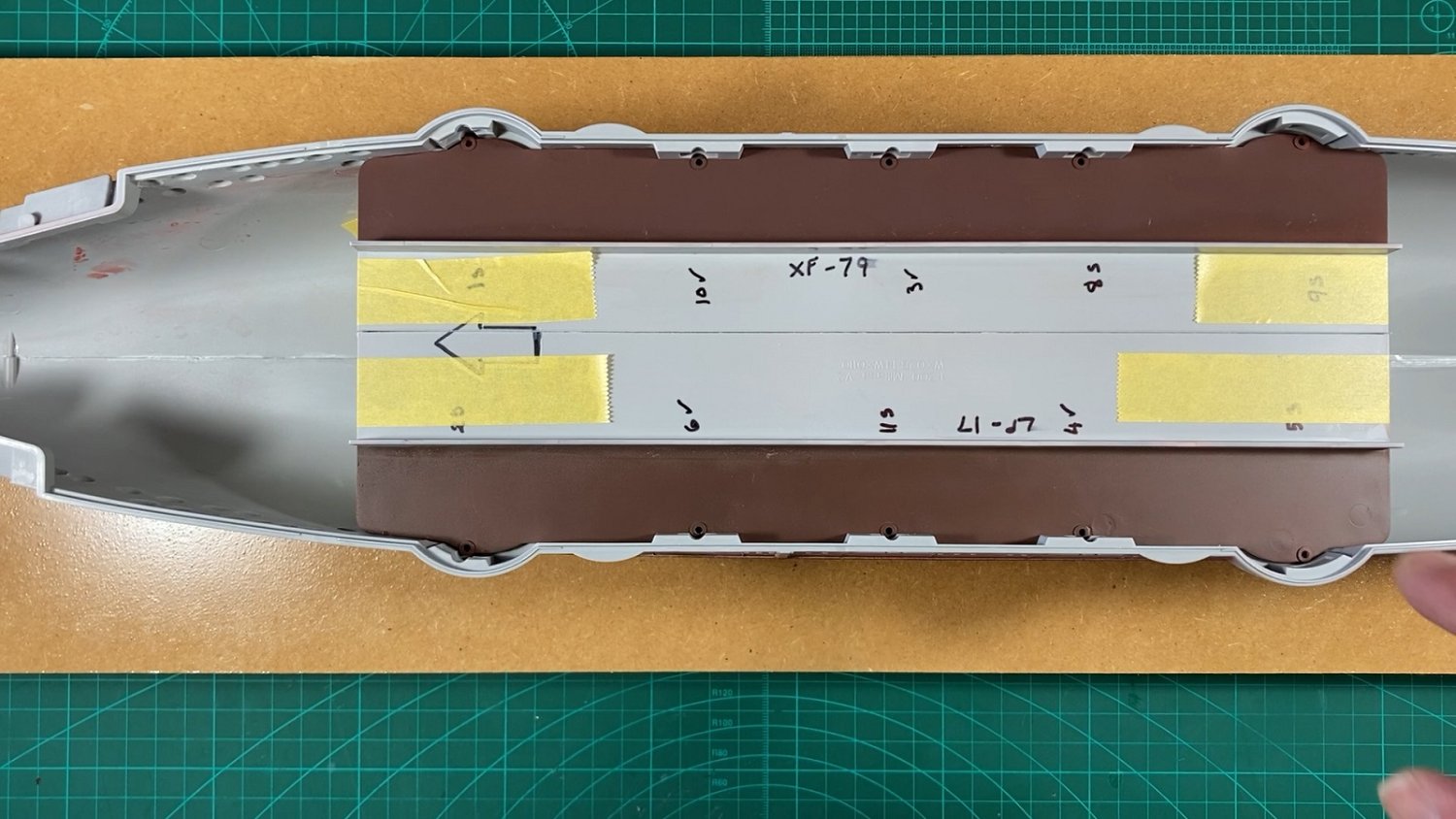
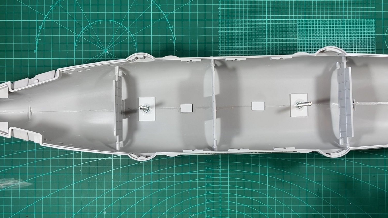
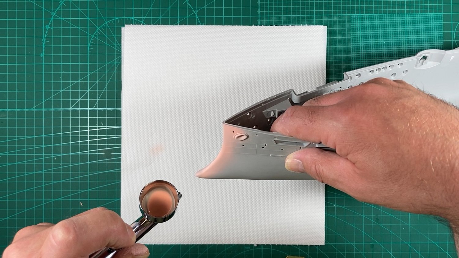
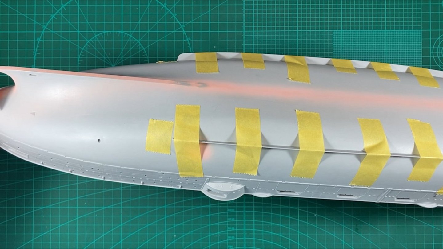
Thanks for all the likes and comments. Part 5 is now done. For mounting the hull I used M5 nuts and bolts, which will allow me to use Pontos pedestals as shown in Richmond’s log if I choose to when it comes time to mount the ship permanently. I made a temporary baseboard with 12mm MDF, a couple of wood strip glued to the 2 long sides and some 18mm wood dowel. This allows me to work on the ship without worrying about knocking bits off when manhandling it. To allow me to mount the ship in a semi-permanent state I wanted to paint the lower hull. After final wet sanding I wiped the hull down with IPA and then followed this with an automotive painters tack cloth. The grey 1500 primer showed up some rough areas at the stern and bow. This was cleaned up with a wet sand using 2000 grit wet & Dry. I started airbrushing on Tamiya Lacquer paint dull red but it was becoming tedious so blasted the hull with Tamiya aerosol TS-33 dull red and achieved satisfactory results to me. Then it was on to the 6” guns. I used Richmond’s tip of dispensing the CA glue onto a candle which greatly extends it’s working time. The pink Mr Surfacer 1500 was used to prime the guns, this was done before the decision to swap to the grey 1500 used for the hull. The grey sprays the same as the black 1500 so was happy for the switch. The guns were top coated with Tamiya’s lacquer LP-14, one of the 4 IJN arsenal paints. This is the colour I will use throughout. Tamiya’s LP lacquer range is a joy to use. Like Richmond I sprayed up the lower gun deck in case you can see past the 6” gun ports but more so for airbrush practice and to test the 2 linoleum colours for preference down the track, XF-79 & LP-17. Rather than force the hull tops apart to get the lower deck in, I scored and snapped it down the middle and installed in 2 halves. I gave a quick varnish to the temporary baseboard using an aerosol can just to make wiping down easier. It's a temp base so wasn't fussy on finish. The YouTube Video Well, my Christmas holidays are over after today so progress will become more sporadic again. Cheers Slog


- 23 replies
-
- 8
-
-

-
- Mikasa
- Merit International
- (and 1 more)
-
Hi Jeff, your Mikasa is looking fantastic. That's a really great idea for the rigging turnbuckles! Cheers Slog
-
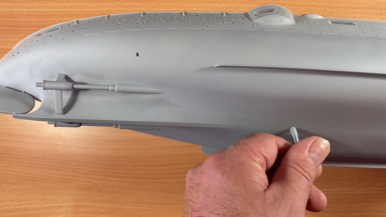
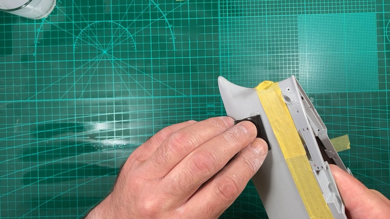
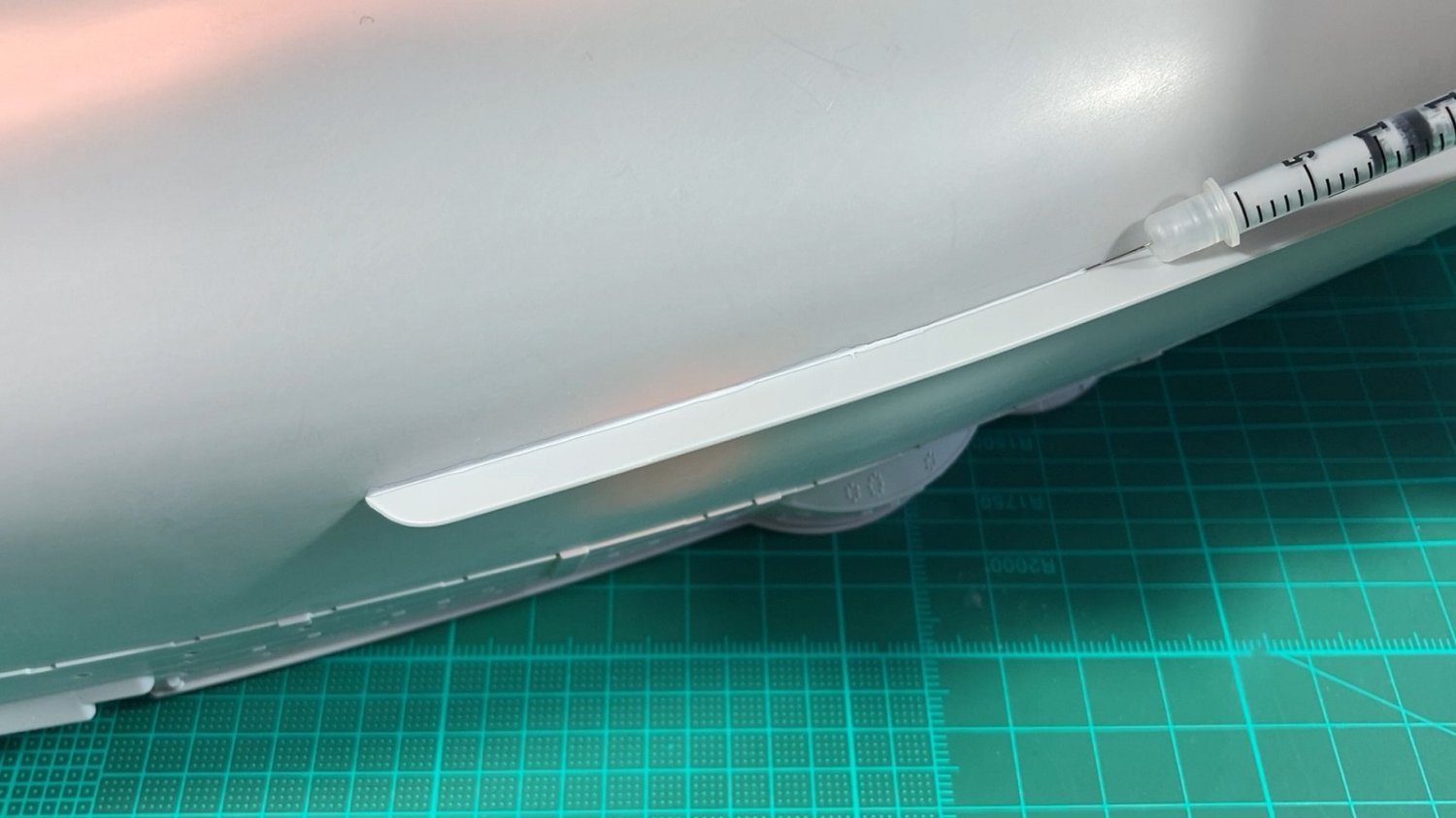
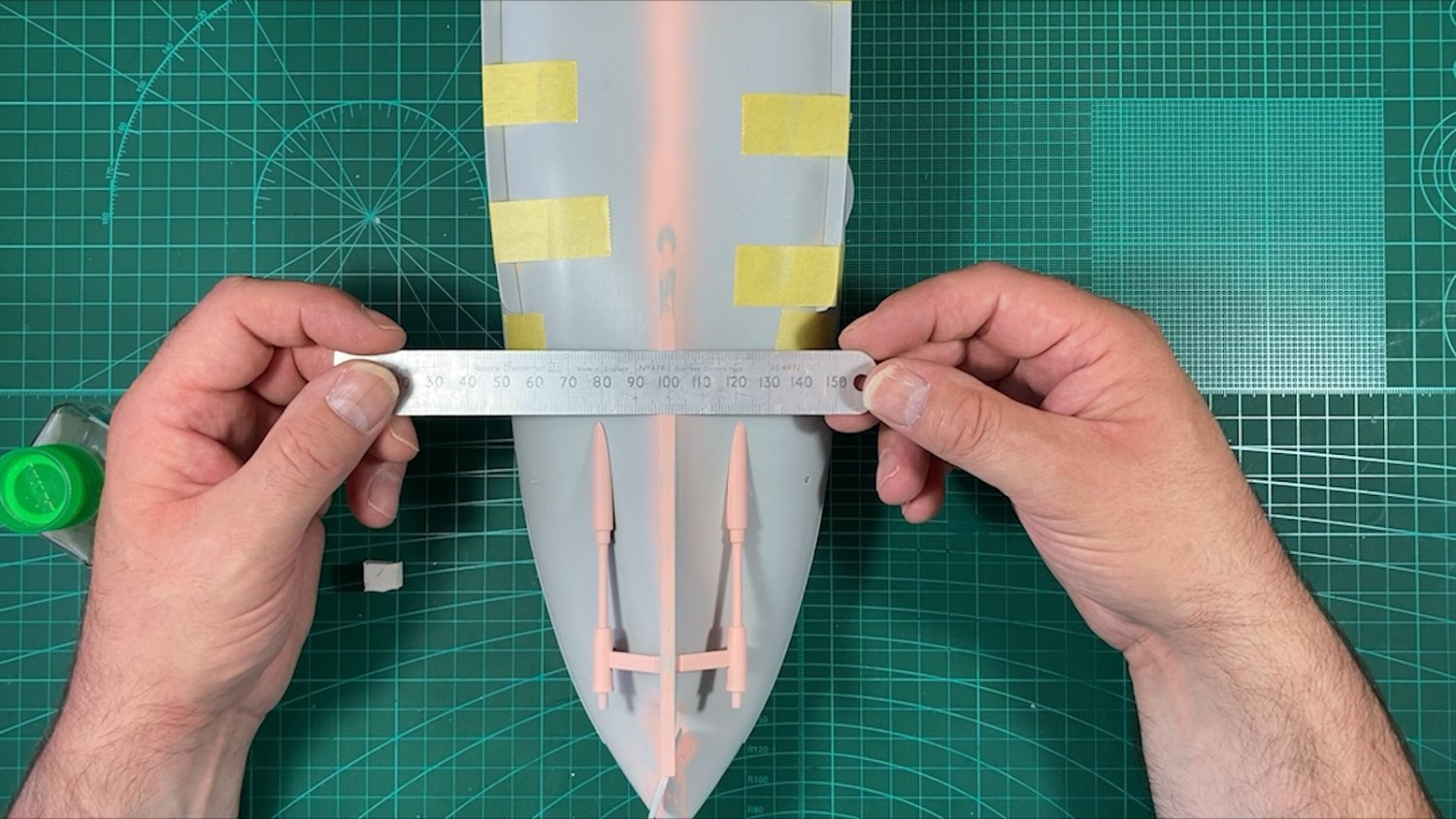
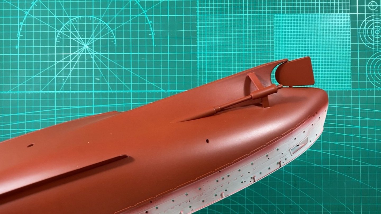
Okay here is my Part 4. I would say based on Richmond’s latest update I have done more or less the same work although I would be trailing behind him overall. Although I do have additional progress/footage that will get carried over to the next part. Again no stills, just screen grabs from the video. With the hull now glued together the seams were filled with ‘sprue goo’ and left for a few days. Whilst waiting for the filler to go off I marked up a number of areas on the hull needing attention such as sink marks, mould lines and some rough areas; the bow had some very faint ripples also. Once the seams were cleaned up with scraping, sanding and buffing, like Richmond, I wet sanded the entire lower hull, in this case with 600 followed by 1200. The Tamiya tape was to protect the upper hull details from inadvertent slips. Priming the seams to highlight any gaps, pin holes etc with Pink Mr Surfacer 1500. The black version is my go to primer and sprays beautifully and is mostly fool proof but I only have dregs left and sold out locally but had the choice of Grey and Pink. I discounted the grey as grey plastic, grey primer and grey top coat didn’t appeal due to visually seeing coverage. I choose the pink...and hate it as the spraying characteristics are so different from the black version and I’m struggling to get decent results. I will pick up grey 1500 tomorrow! Bilge keels taped in place and glued with Tamiya Extra Thin. There were half a dozen or so pin holes on the hull halves seams, which needed filling and small dabs of Mr Surfacer 500 took care of them. As Richmond noted the bilge keels aren’t a great fit and need filling on both sides. To minimise clean up I tried applying Mr Surfacer 500 with a syringe and it worked great. Mostly 2 applications was sufficient to fill (one area required 3 passes) and was quickly cleaned up with cotton buds moistened with Mr Hobby Levelling Thinners. Installing the prop shafts/housings and checking for consistency. Good place to stop for Part 4, with the hull glued up, seams taken care of, the prop shafts and bilge keels installed, filled and cleaned up. And of course the YouTube video link Cheers Slog


- 23 replies
-
- 9
-
-
- Mikasa
- Merit International
- (and 1 more)
-
Hi Richmond, you are progressing well, probably a bit a head of where I'm at. I found the bilge keels fiddly to attach also and needed to watch them as I bumped them twice and each time heard a creak but luckily no damage. My hull seams weren't to bad also but the stern needed plenty of filling as couldn't get it tightly together. Agree with the prop shafts such bad seams to fill, although your primed ones turned out well. Agree with the lower deck but I'm also going to paint even if just for some airbrush practice as I seem to be out of practice. Just a note on your styrene strip, I think the lower deck walls provides support to the main deck so you might have to trim the styrene down flush with wall. Good to see you took my advice on the mounting nuts for the pedestals as I secured mine to the hull yesterday and when attached to temporary pedestals/baseboard the hull was rock solid. I really like the Pontos pedestals in your picture and may have to get them when time to permanently mount. I experimented with masking and Mr Surfacer 500 for reinstating the hull plating lines but wasn't happy with the results so will use stretched sprue like you. The black card in the folders as a nice touch, makes it clearer what fret you are looking at. Your portholes look really neat, I haven't done any yet so may have to use your method. What's the pen like thing on the right with the blue tip...is that like a pick up pencil? I'll post part 4 of my progress later today some time. Cheers Slog
- 17 replies
-
- 3
-
-
- Mikasa
- I Love Kit
- (and 2 more)
-
Hi Richmond, an alternative to burning is once you have used all the candle top surface is to let the CA harden and then it can be prised up and picked off like a scab…which is oddly satisfying!
- 17 replies
-
- 3
-
-
- Mikasa
- I Love Kit
- (and 2 more)
-
Nice work, good to see some progress. the pontos turned brass barrels are nice and a great replacement. Did you paint the MR metal primer with a brush or airbrush? I’m keen to see if it works. I got SMS brand for this but still aways off from the 6” guns. Guessing the candle is for the dispensed CA glue? I was going to epoxy glue my barrels but may super glue if worked out okay with yours.
- 17 replies
-
- 3
-
-
- Mikasa
- I Love Kit
- (and 2 more)
-
Thanks. Yeah do a trial or two to see how you go. I still have a good few to go so imagine some repairs will be inevitable. It is strange, doesn't make sense for Pontos to leave them out.
- 23 replies
-
- 3
-
-
- Mikasa
- Merit International
- (and 1 more)
-
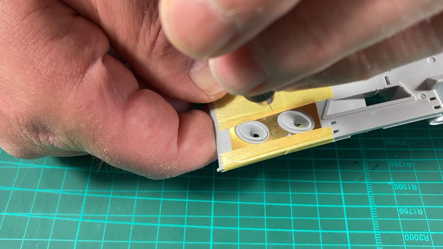
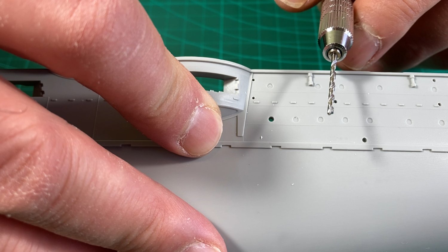
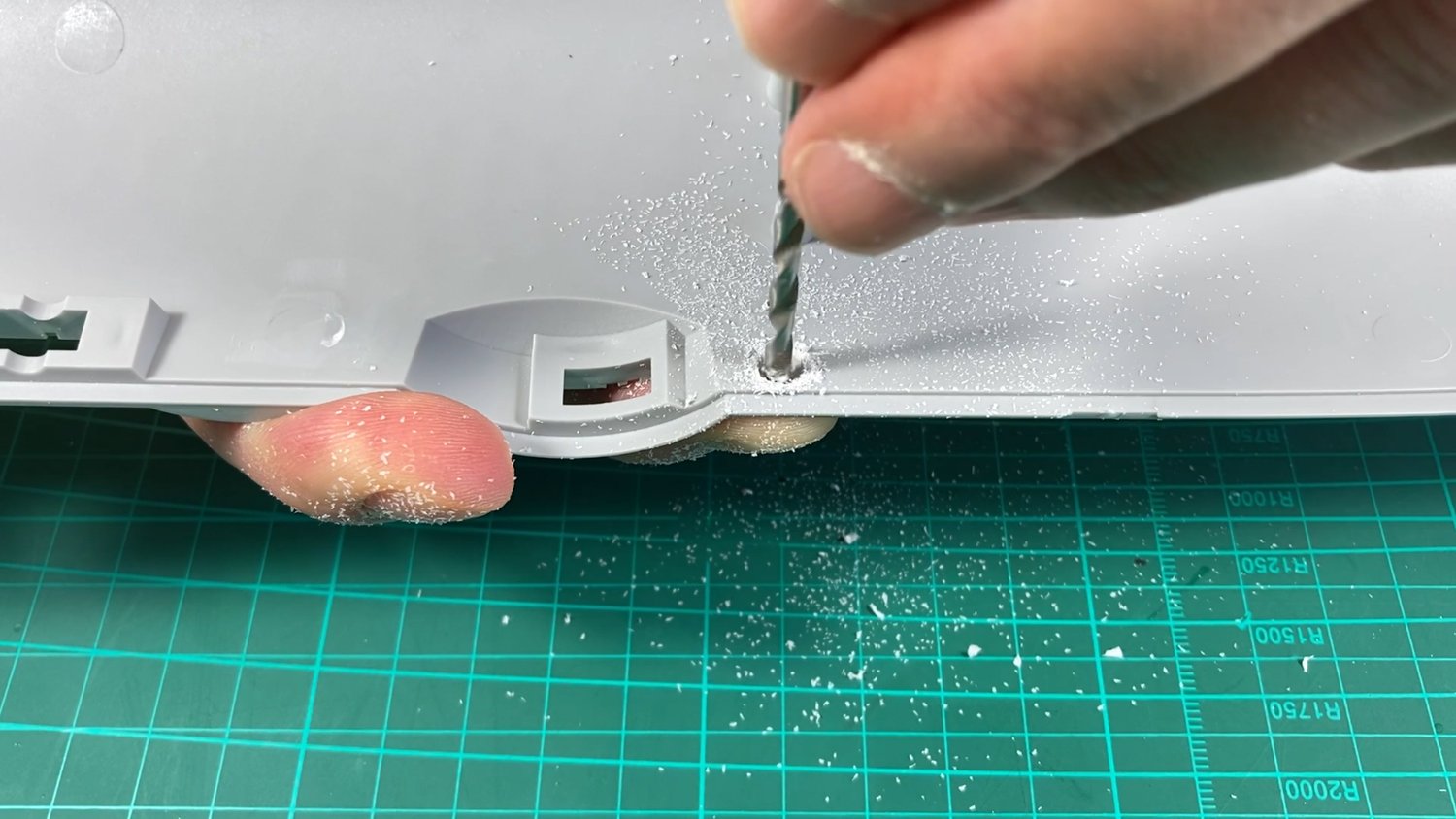
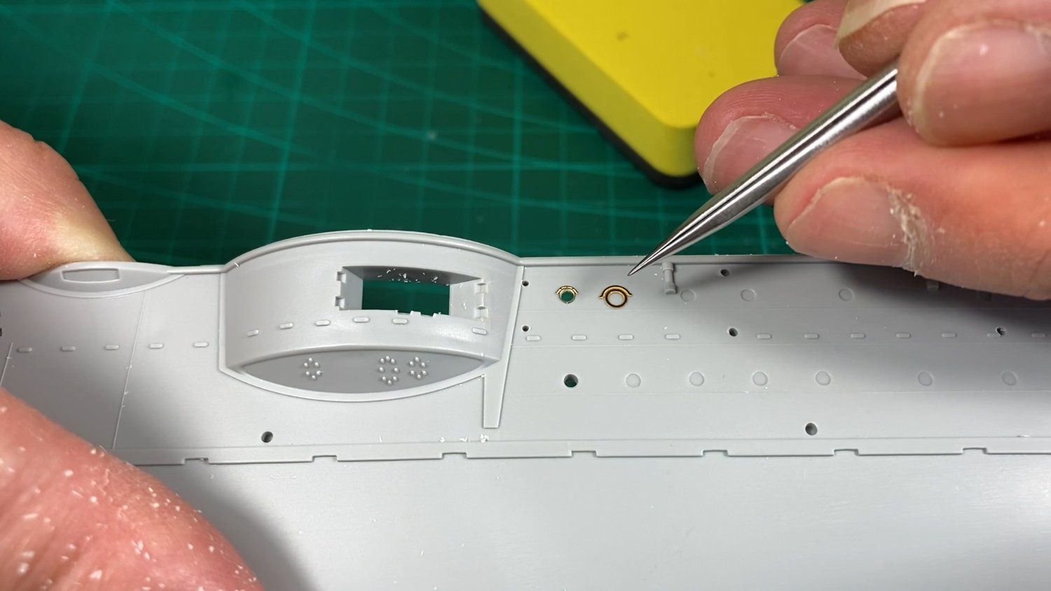
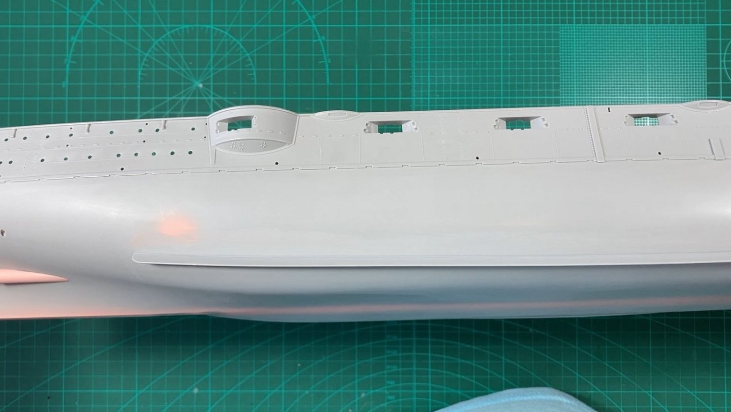
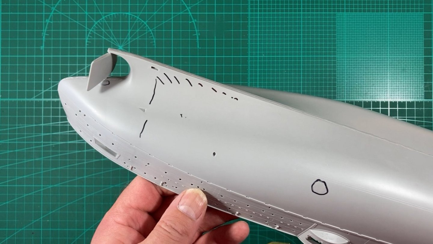
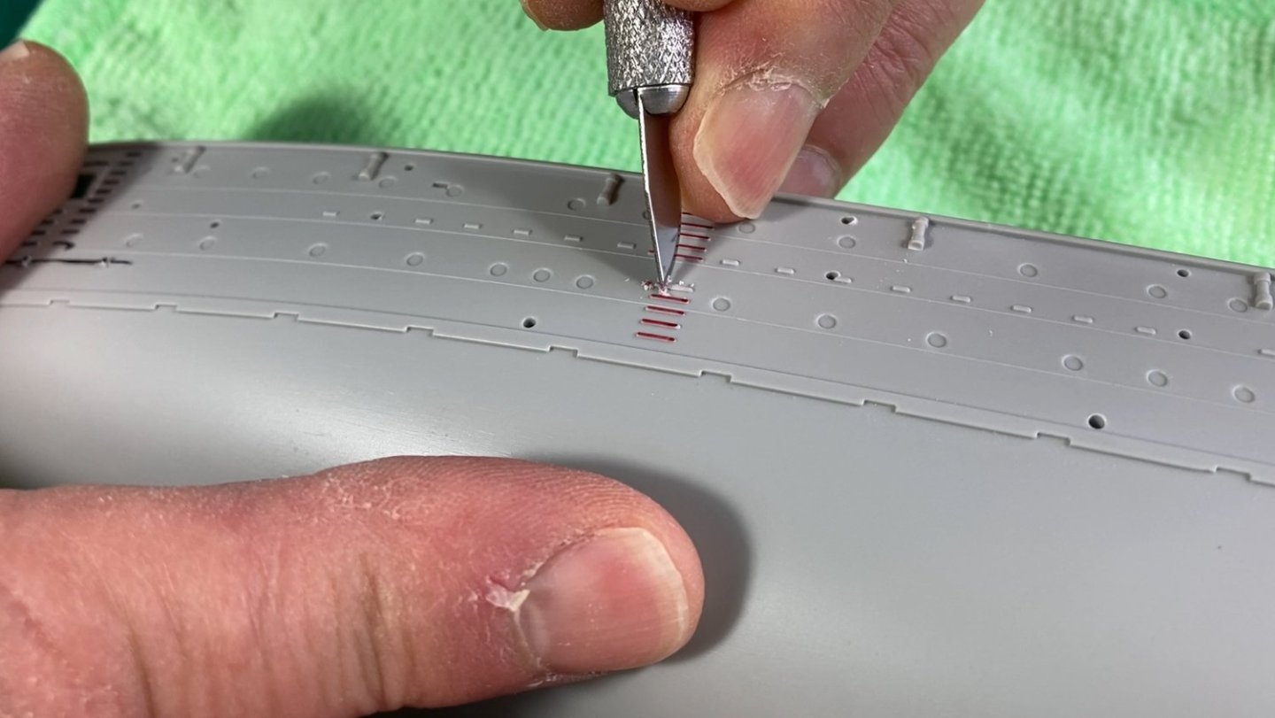
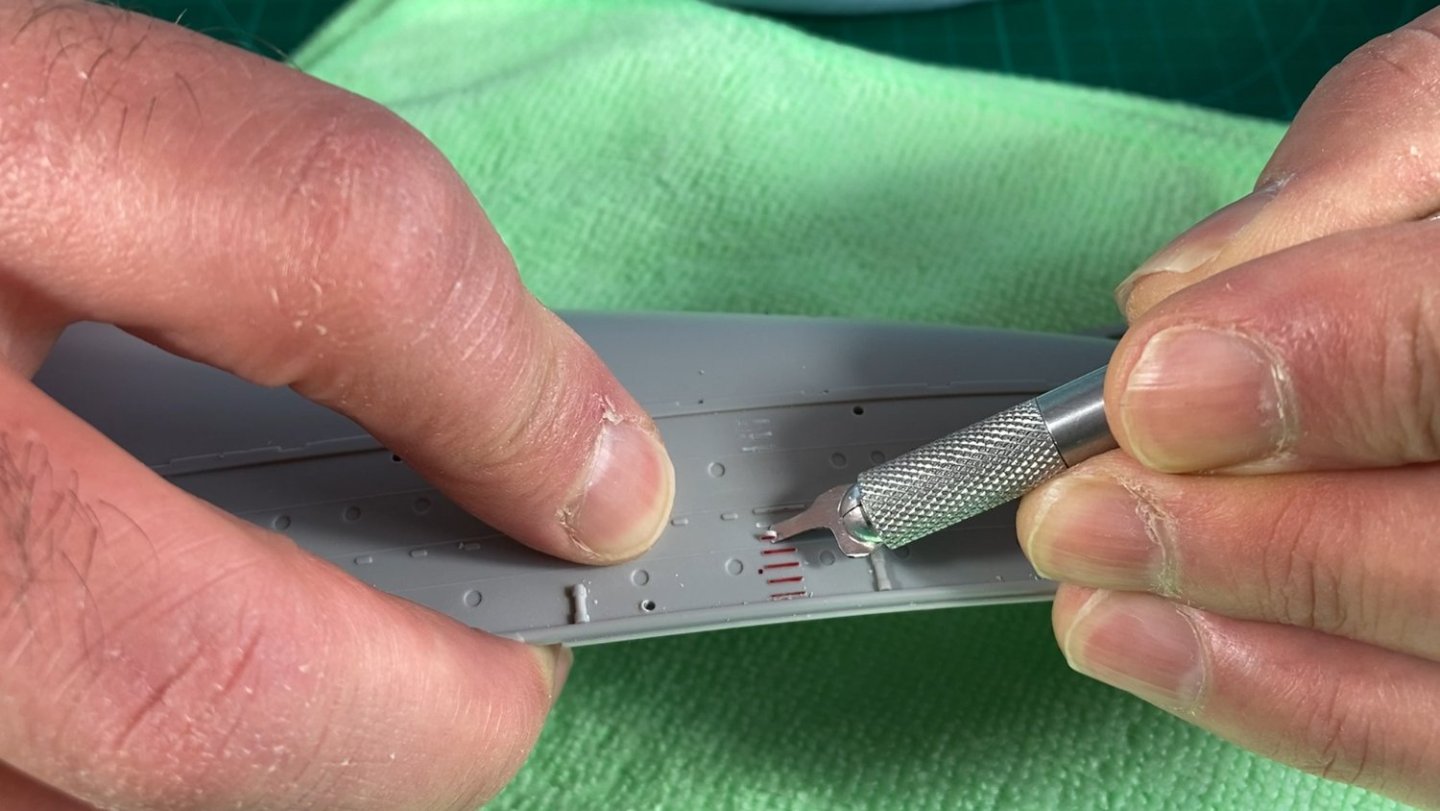
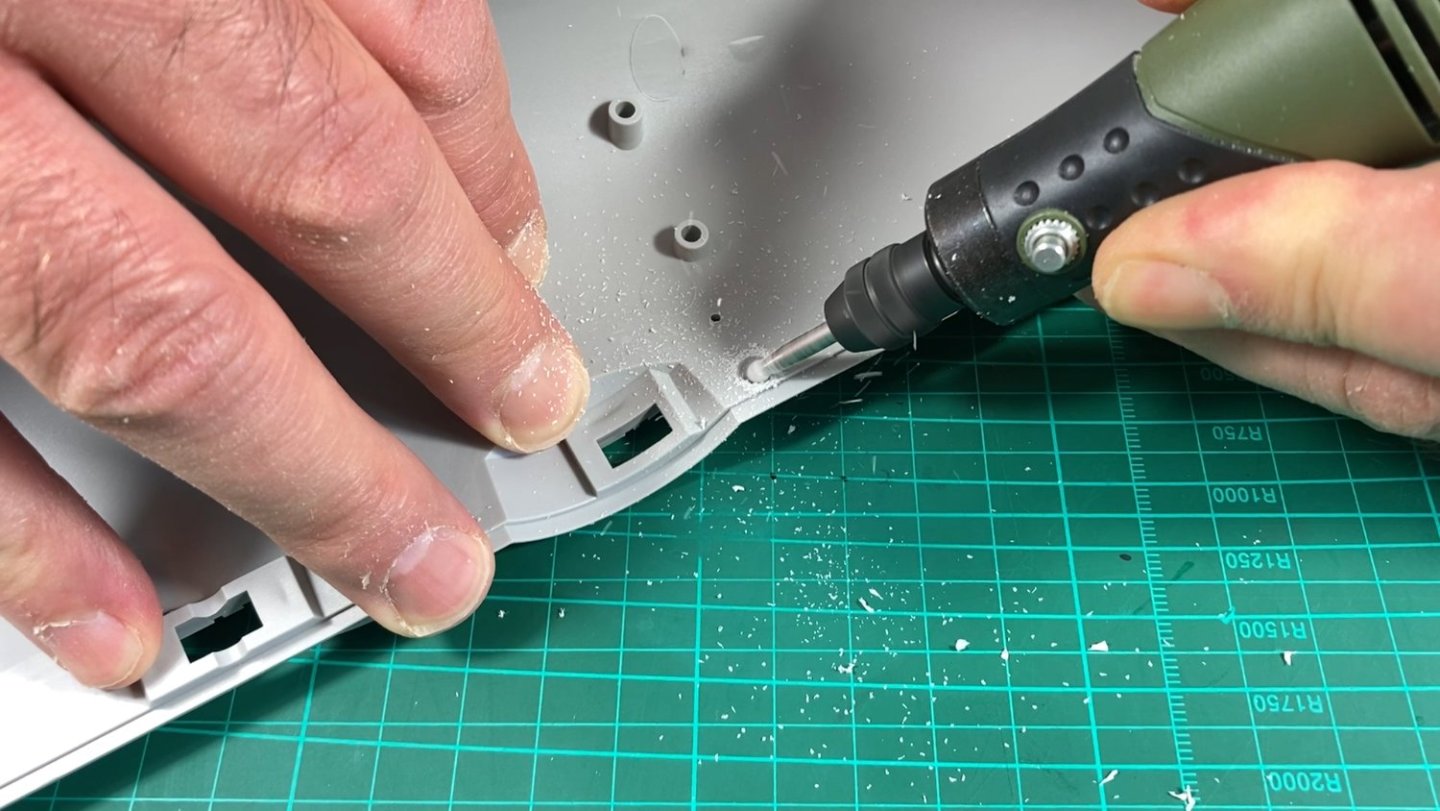
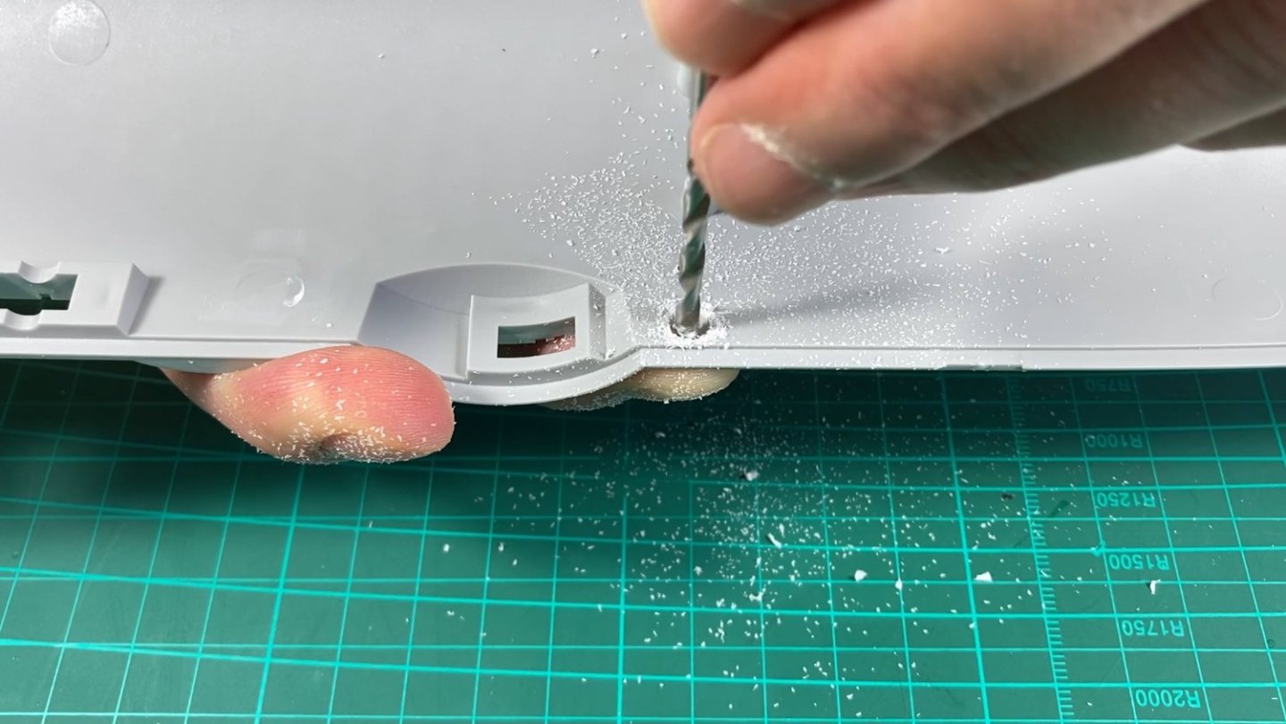
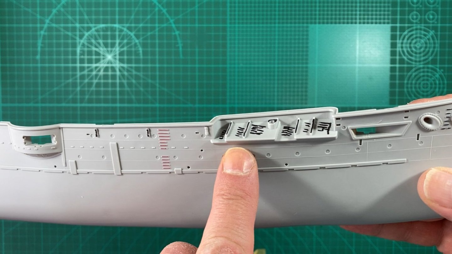
Thanks for the comments and likes. After twisting Richmond’s arm, the starting gun has been fired and we are off at a sprint. Part 3 deals with removing extraneous mouldings and making holes, all in preparation for the Pontos details. Just a note about the pictures. I don’t intend to take any still photos, relying instead on taking screen grabs from the video’s so apologise in advance for having my grubby little fingers in every shot. First up is to go through the Pontos and MK1 instructions and highlight everything to be removed. I used black marker for the Pontos stuff and red for the MK1 items. Removing the steps by scrapping with a round blade. From watching many YouTube videos this seems a fairly standard method. However it is pretty slow going so decided to try the home made chisels from old No.11 blades I make to remove parts from paper models. This sped things up immensely and a step could be removed with one or two passes. I still needed to do a final scrape with the round blade to avoid damaging the surrounding hull. Next up is drilling all the holes for the PE hull steps. Pontos provide photo etch templates for this work although it’s disappointing that Pontos don’t replace all hull steps (ladders?). I will use the MK1 steps to cover the missing Pontos ones. Unfortunately, the MK1 set doesn’t provide templates for their steps but I will utilise a Pontos template so that the spacing is consistent. Pontos require a 0.4mm drill and a quick test on scrap styrene confirms the MK1 steps use this size as well. Then on to the portholes. I centre marked the porthole with an old airbrush needle by eyeballing it. Tried passing different size drills through the PE porthole until found one which just goes through. Turns out 1.5mm is the size. 1.6mm is just a fraction too tight. With the porthole drilled out it was required to relieve the backside due to the thickness of the hull plastic being 2mm to 3mm. This equates to a real thickness of 400mm to 600mm! The thick plastic spoils the look of the porthole. I tried removing this with just a drill but hard work and decided to use a carbide burr in the Proxxon rotary drill to remove the bulk of it….with the obvious dangers! By finishing slightly back with the carbide burr, a smaller drill could be used to remove the last fraction. Once the drill point touches my finger, it’s twist/check/twist/check etc until happy. With the porthole…hole? drilled I thought I would show a comparison of both sets PE portholes. Pontos on the left and MK1 on the right. The Pontos one is so much more refined and delicate and these are what I will use. The MK1 is quite chunky and bland in comparison. I am aware that the PE portholes are incorrectly represented by sitting on the hull surface like this and in reality would barely be visible sitting behind the hull plates but they are provided and to be honest I like the effect so going to use them, which doesn’t require debating. The YouTube link to the video in case anyone wants to listen to my dulcet tones. Cheers Slog


- 23 replies
-
- 7
-
-
- Mikasa
- Merit International
- (and 1 more)
-
Nice! The photos look fine! I really like the size comparison with 1/200 Bismarck, shows how big these battleships developed over time. I also didn't realise how big 1/350 battleships are! See you got your Tamiya anti-static dust brush as well, really handy. I found my fore deck didn't fit that great due to some really big ejection pin marks on the inside of the hull. Once cleaned up they fitted well and hoping I can just rely on tape to hold when time to glue. Nice Idea with the sprue identification clothes peg! May have to 'borrow' that idea. Can you tell more about the soldering station as I will need something similar at some stage to replace the rubbish hardware store ones I got? Cheers Slog
- 17 replies
-
- 4
-
-
- Mikasa
- I Love Kit
- (and 2 more)
-
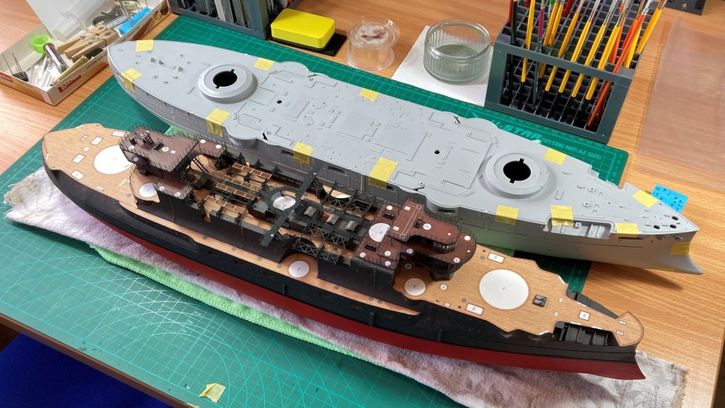
Welcome to the start of my Mikasa log, which is a group build with @Richmond Here is a link to Richmond’s log which explains it. I got this back in 2016 which was the first release of the 1/200 Mikasa by Merit International (Trumpeter). I also got the KA-Models MK1 Design detail set around the same time due to difficulty in finding the Pontos set. Fast forward to earlier this year and after catching up with Richmond we decided to build the Mikasa together as a group build. For this I purchased the Pontos set which will be the primary set used and utilising some bits and pieces from the MK1 Design set. To get going here is a comparative photo of Mikasa alongside its Battle of Tsushima adversary, Borodino. Don’t worry Richmond, just a test dry fit 😊 I am also documenting the build on YouTube and have linked Parts 1 & 2 below reviewing the kit and detail sets respectively. Really excited and itching to get going with this. Cheers Slog
- 23 replies
-
- 10
-
-
-
- Mikasa
- Merit International
- (and 1 more)
-
@Richmond Great introductory post. Really looking forward and excited to start building alongside with you.
- 17 replies
-
- 4
-
-
- Mikasa
- I Love Kit
- (and 2 more)
-
WWII Sunken German Warships Exposed by Drought
Captain Slog replied to mtaylor's topic in Nautical/Naval History
Low background steel is to do with contamination with radiative nucleoids, however it has to do with when the steel was produced (pre-nuclear bomb testing) not where the steel has been or what conditions the steel has been under. https://en.wikipedia.org/wiki/Low-background_steel -
Hi Chris, can you explain how you cut these out without damaging the part and what with as I can’t work out how it is so neat without a cutting Matt under it and guide ruler etc
-
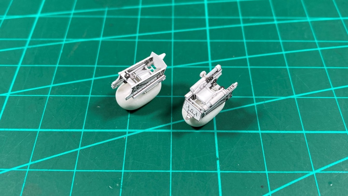
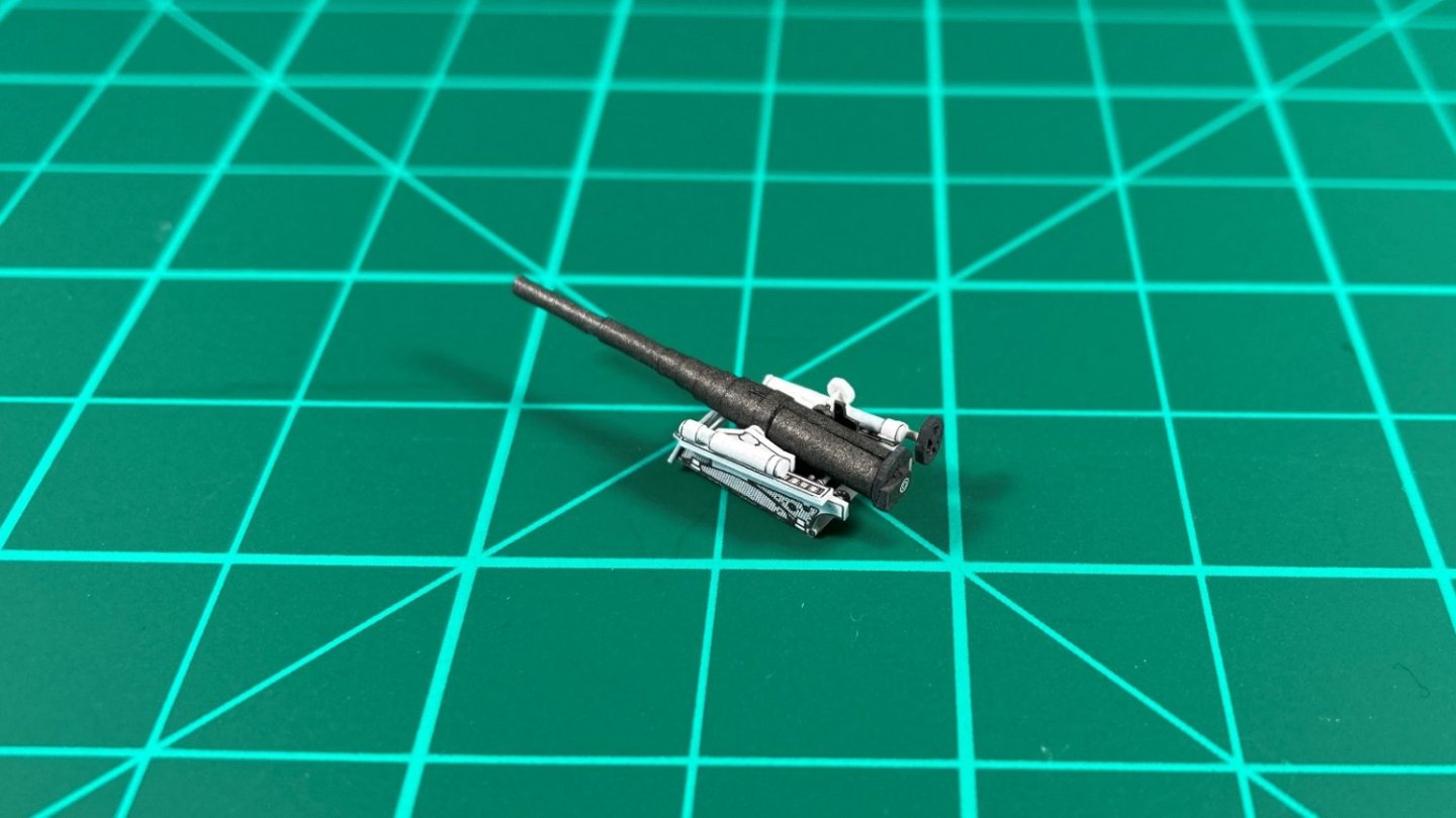
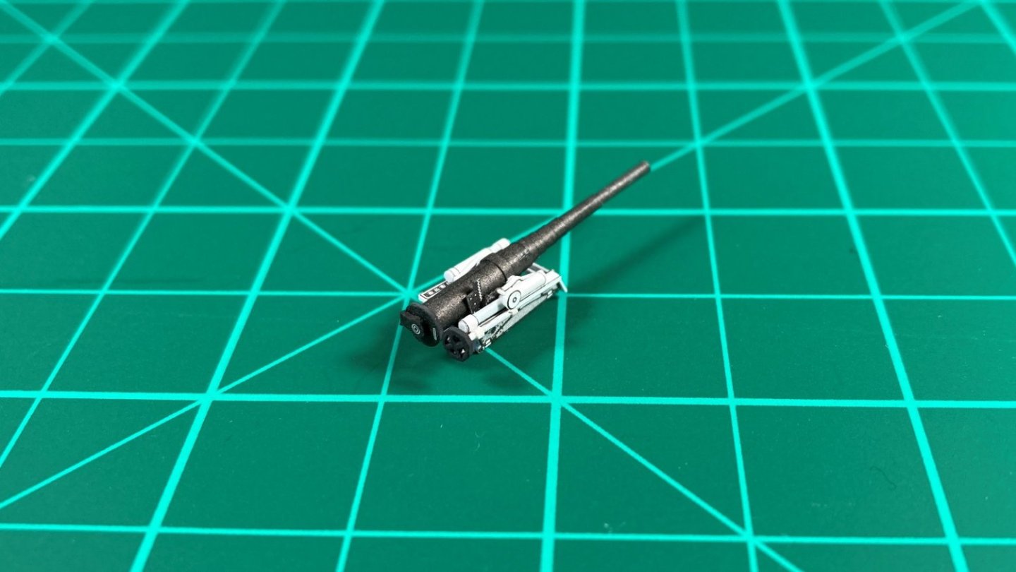
Hi all, Part 9 Well, the 6” guns are finally finished…kind of! The first 2 photos show all the details assembled on and in the carriages from previously posted Part 8. 5x 0.3mm wire parts, 3 with ‘worm’ gears. A couple of spur gears with 0.5mm shaft for gun training and a small paper gear. The main recoil cylinders and a drum for gun elevation. Next photos are of a finished gun. The breech was installed as well as the elevation gear on to the barrel. I ended up cutting out and using the paper handwheel as decided soldering ones from brass wire just wasn’t worth the effort. I used 0.5mm wire for the handwheel shaft. Additionally I wrapped the handwheel shaft with some thin paper to better represent the diagram and to give a better paper to paper bond. Last photo shows the finished gun and the remaining 9 completed gun carriages (minus handwheel and shaft) I still need to attach the 4 carriage wheels per carriage but will wait until in a position to permanently install them to prevent damage. The gun barrels for eight guns still need to be done but struggling with this. I had done 2 so far (the one in the photos and another not quite as good) but destroyed the next 2 so will need to cut out new ones using the kit ones as a template. I just can’t get a reliable method to roll these but will persevere. And of course the video which shows the construction of the guns. The next part will be the start of the hull skinning and gun installation. Cheers Slog


- 13 replies
-
- 9
-
-
-
-
- Dom Bumagi
- Admiral Nakhimov
- (and 1 more)
-
Absolutely stunning!