
Captain Slog
-
Posts
904 -
Joined
Content Type
Profiles
Forums
Gallery
Events
Everything posted by Captain Slog
-
 I have used small diameter brass rod for bollards in the past which can be squared off using a photo etch file.
 -
Thanks, not sure about that though. To make things worse, other than the gun barrel sticking out of the gun port very little of them will be seen. Also contemplating punching out 140, 1mm discs to cover the open ends of the tubes as don’t look right not being closed in. 40 of them will need another 0.5mm hole punched in middle and 60 of them require a 0.3mm hole pierced in them…will do some samples to see if worth it before jumping in. This could just be me but I think the reason I don’t lose parts often is due to my favourite tweezers needing very little pressure to close them so imparting very little pressure to the parts. I found that tweezers requiring more pressure to close are harder to fine control and find myself doing mental juggling trying to regulate the pressure to hold the parts due to fingers applying pressure just to keep the tweezers closed. I find this more fatiguing and distracting from the task at hand. That's my theory anyway! Thanks Chris, you can also stack them taking up very little space and just grab the particular one that you want to work on at the time…just don’t knock them over lol
- 13 replies
-
- 5
-

-
- Dom Bumagi
- Admiral Nakhimov
- (and 1 more)
-
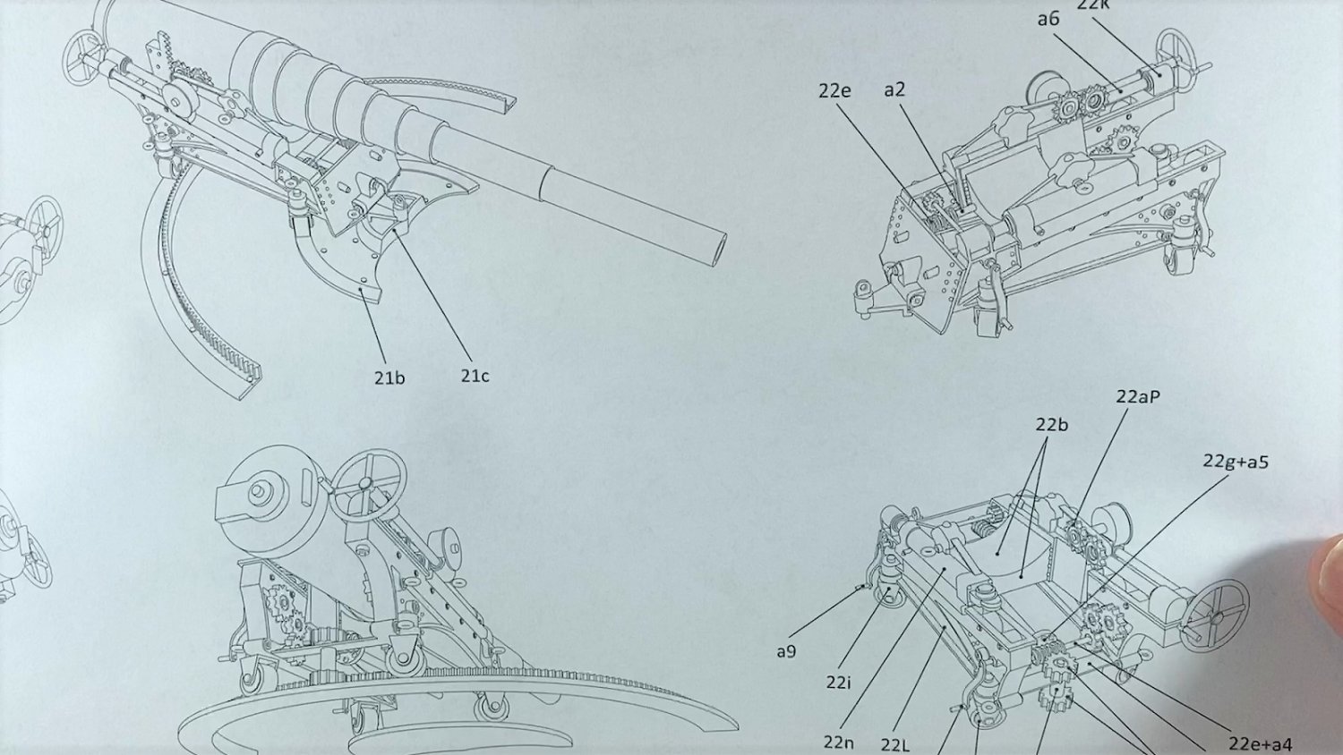
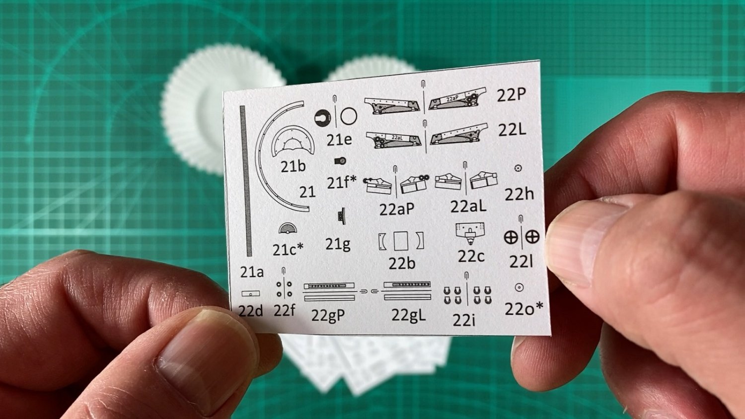
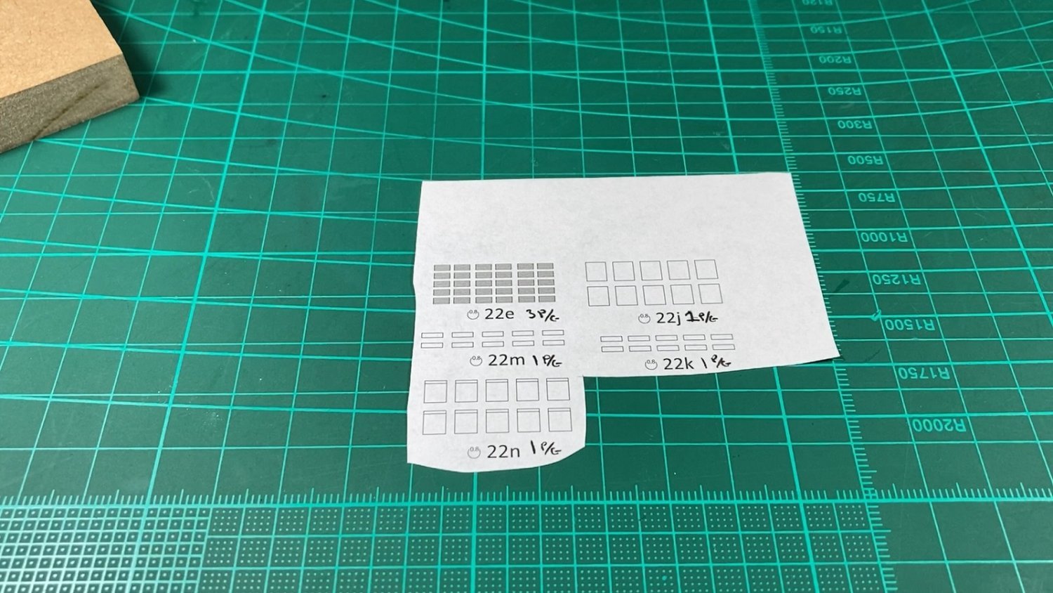
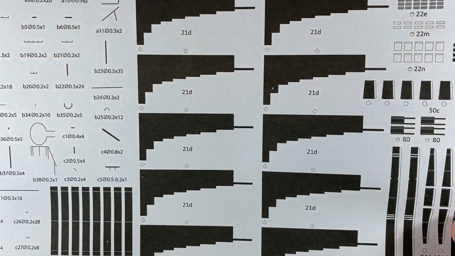
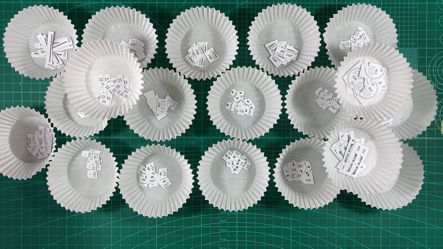
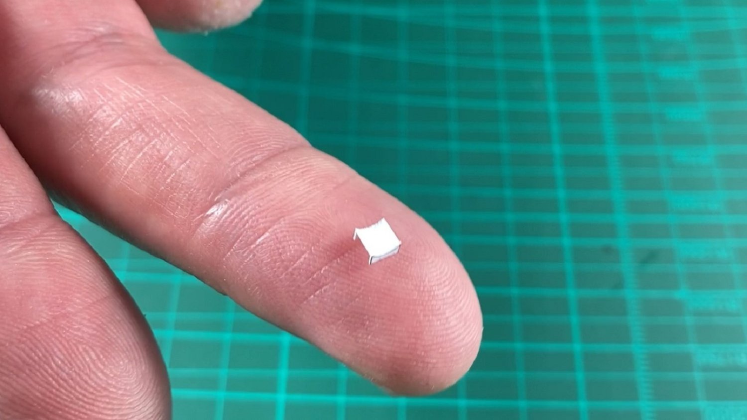
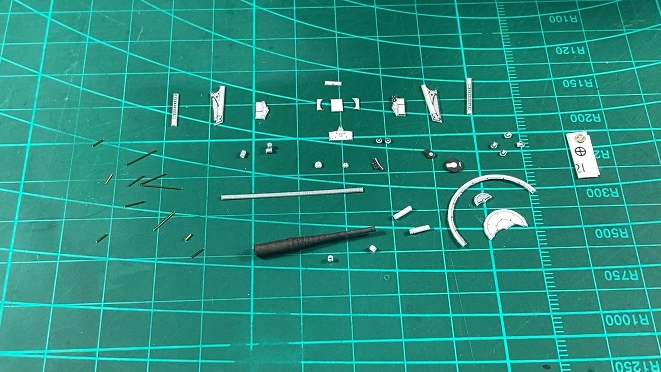
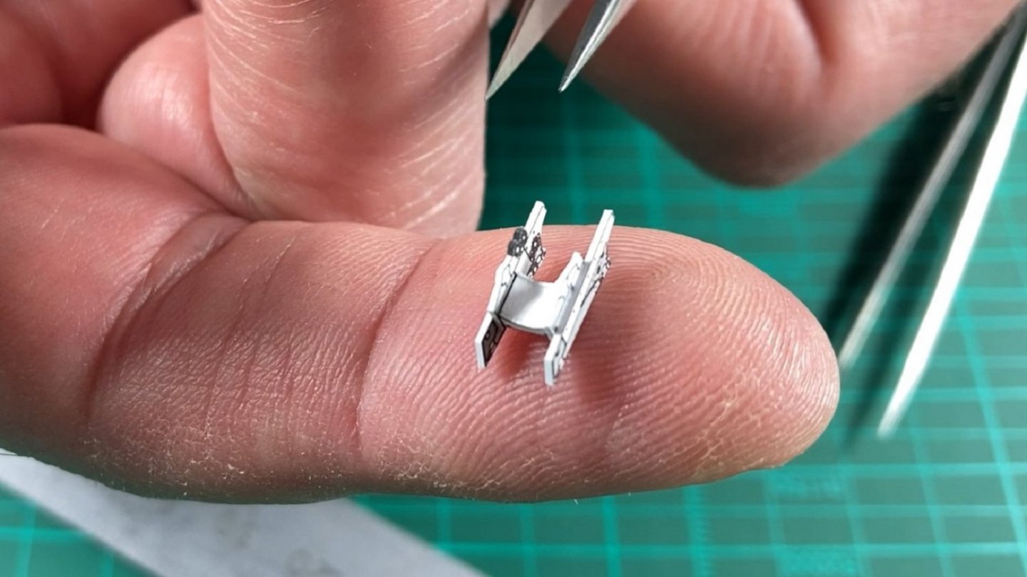
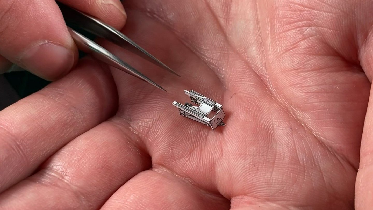
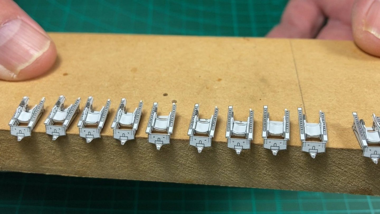
Hi, I started working on the 6” guns next as these will be required prior to skinning the hull as they live on the lower deck. Due to the number of parts involved, their construction is spread out over several videos. Note: I haven’t been taking stills photos of the progress, so these are all screen grabs from the videos, hence my hands and fingers in the photos. Part 7 Part 7 only covers cutting out and prepping the parts ready for assembly as there are 48 parts per gun and 10 guns for a total of 480 individual parts. There were 90 parts to be folded and 30 parts to be laminated and 70 parts to be rolled, excluding the 10 gun barrels. This photo shows the gun construction diagram. There are more views not shown. The regular thickness paper parts for one gun. The thin paper parts which are to be rolled into tubes. The thin paper barrels (21d). These will be my 1st time rolling paper barrels as always had replacement brass barrels up until now. I did search but couldn’t find brass equivalents. They are very distinctive hooped barrels. All the parts, folded, laminated and rough cut out ready for final trimming. Used cupcake cases to keep them in order. Some of the more straight forward parts cut out, which wasn’t filmed. The smaller, more difficult or curved parts were covered in the video. All parts for one gun cut out ready for assembly. Also showing my 2nd attempt at gun barrel rolling. The 1st attempt was passible but will need the end of the barrel painted as the printing was damaged with some white showing. I didn't cut out the hand wheels as I hope to solder these up out of brass wire. Associated Part 7 Video Part 8 Part 8 covers the assembly of the gun carriages only. 1st up was making the centre saddle from 3 parts. The saddle was then used to join the carriage sides together which had 2 parts each. Different sized left and right top rails and the front plate fitted. A rear brace was also fitted and all 10 gun carriages ready for the next step. Associated Part 8 Video Hopefully I will be able to attach all the tubes and wire parts in the next video finishing the guns. Cheers Slog


- 13 replies
-
- 10
-

-
-

-
- Dom Bumagi
- Admiral Nakhimov
- (and 1 more)
-
Your hull plating looks far better than my 1st attempt at it…or 2nd attempt for that matter. Impressive!
-
Looking forward to following your progress. I agree with the laser cut forms, quick easy process to get noticeable results. Hull skinning is my nemesis also!
-
Well done, looks great!
-
Nice work, particularly with the vents! I struggle with them.
- 23 replies
-
- 3
-
-
- card
- World of Paperships
- (and 2 more)
-
Coming along nicely! I like problem solving, gets the mind working.
- 23 replies
-
- 2
-
-
- card
- World of Paperships
- (and 2 more)
-
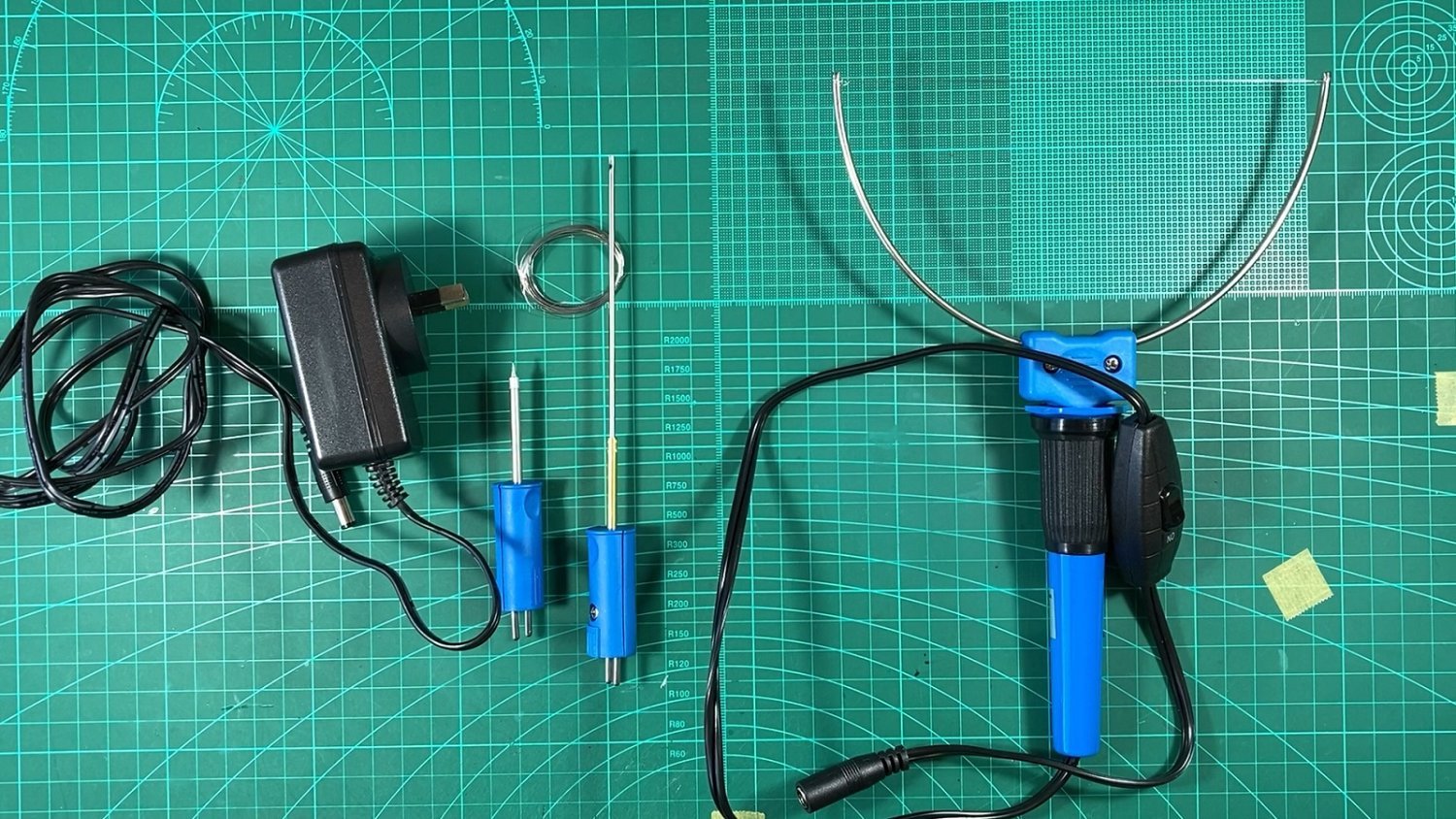
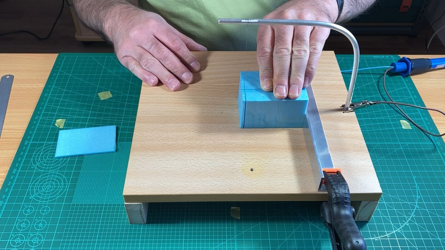
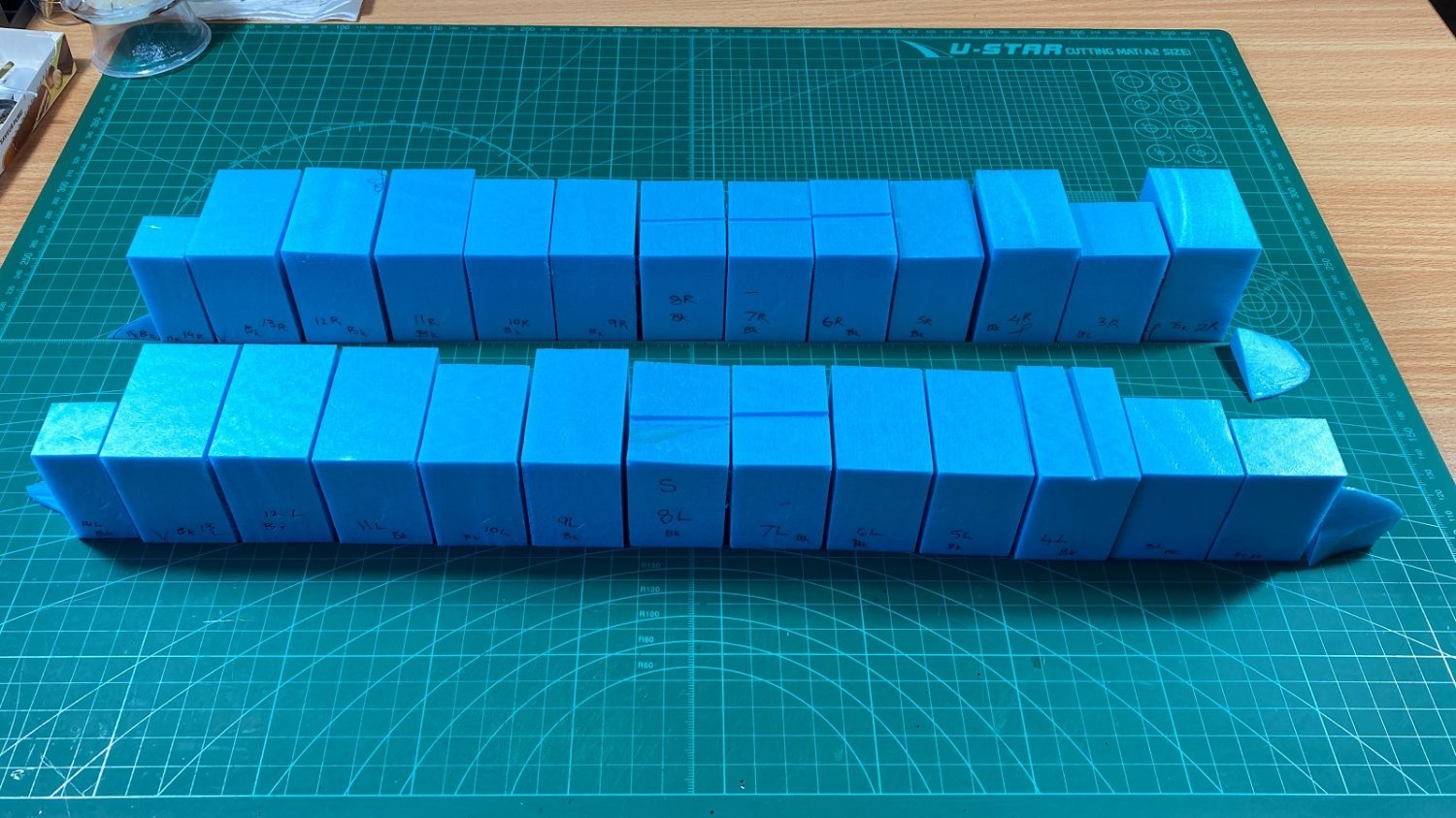
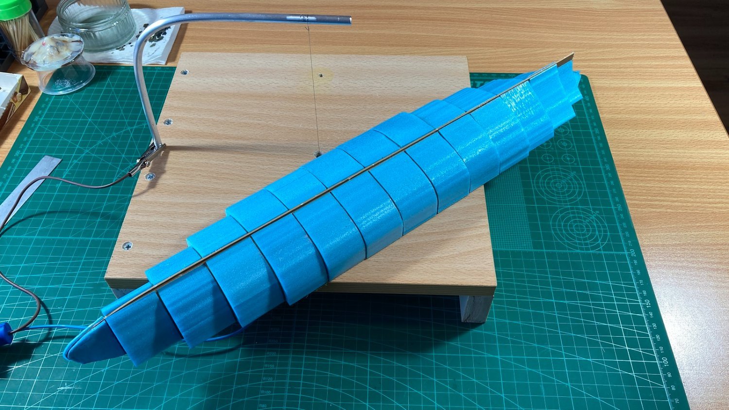
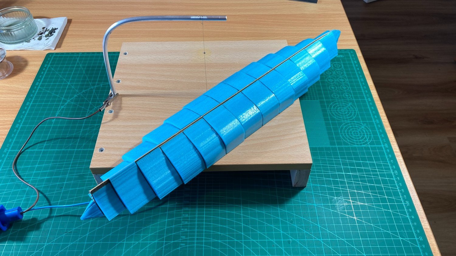
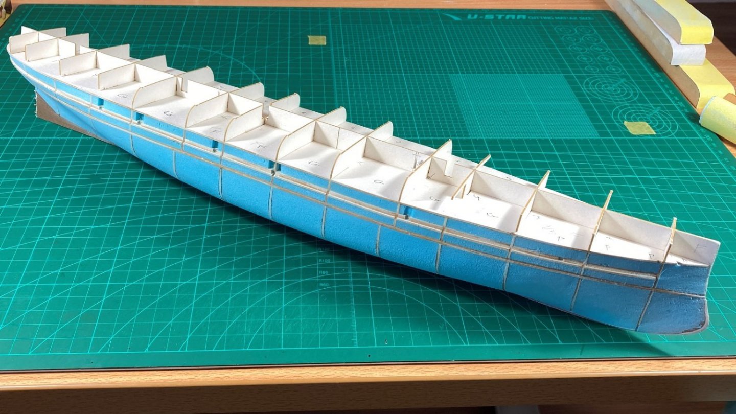
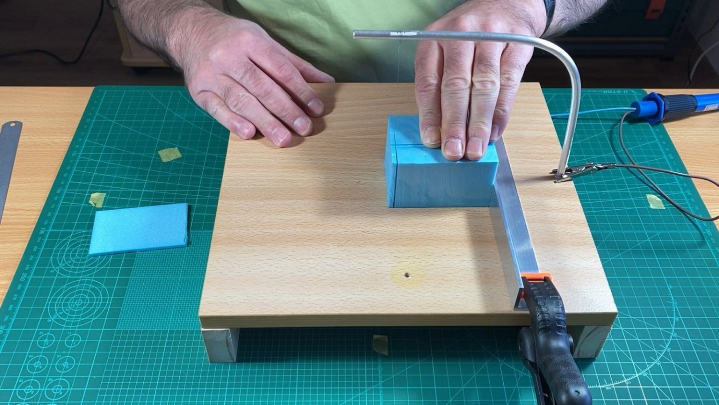
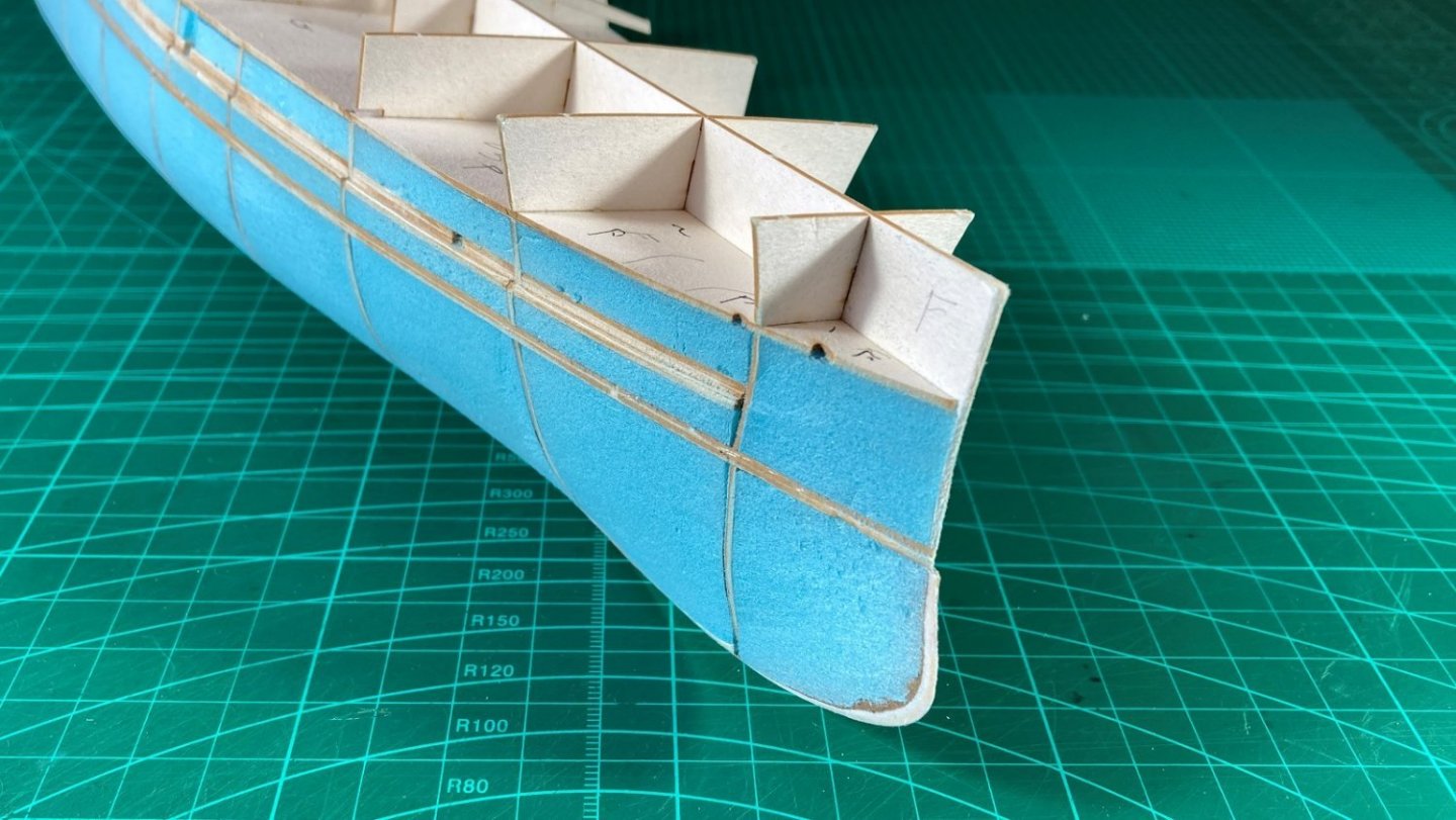
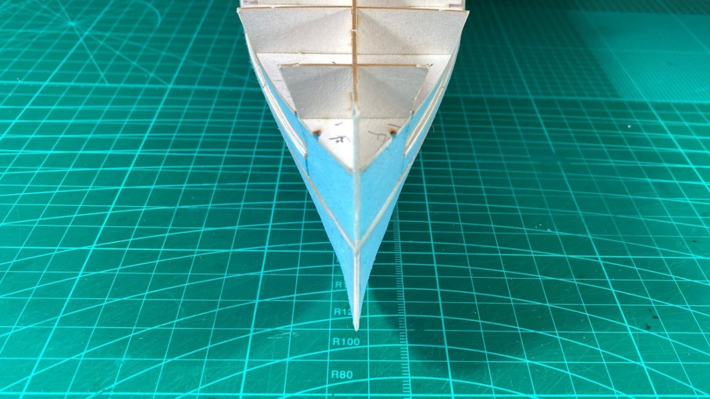
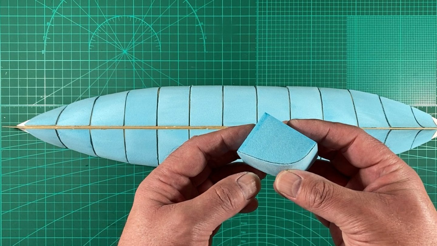
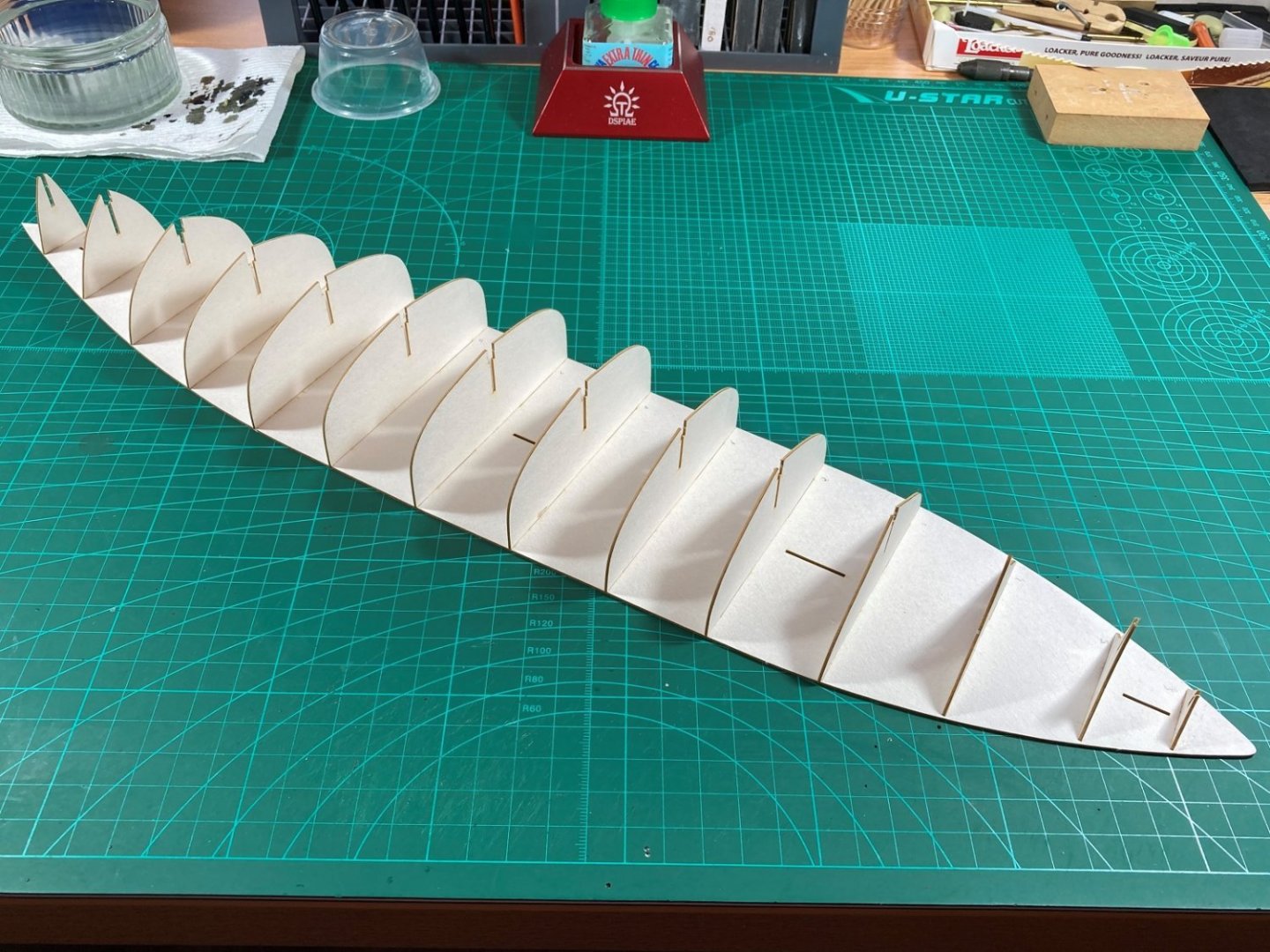
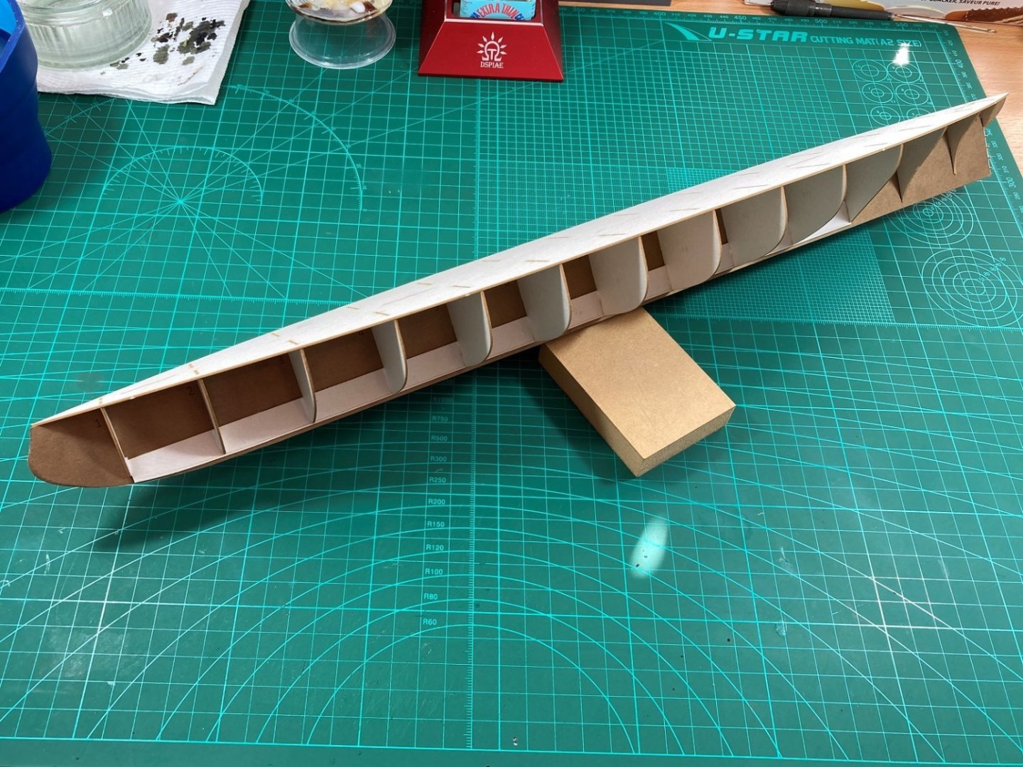
Hi All, I have been working on the hull for the past few weeks and have a couple of parts to cover. Part 5 I decided to fill in the hull spaces with XPS foam after finding a local distributer and got a 'handy size' sheet (800mm x 600mm) of 50mm. I also picked up a cheapish generic free-hand, hot wire cutter at the same place as per the picture. Being free-hand, it wasn’t ideal for making straight accurate cuts but by using bits and pieces in the hobby room (like a little storage cupboard door) I was able to utilise, by modifying, parts of the free hand cutter to make a cutting table. I had to buy the 6mm aluminium rod for the arm and the aluminium angle for the fence. I could then cut the foam to size to fit between the laser cut bulkheads. Photo shows 15 pieces per side and marked up to go into position. The associated video. Part 6 This is a continuation from above and the first step was to use the hot wire table to remove the bulk of the waste foam. The blocks are not glued at this stage. Each block was then rough sanded individually leaving the line in place for final sanding and overall fairing. The hull halves where then glued together, the foam blocks glued in place then the final sanding and fairing followed. Photos of the finished (for now) hull. I am hoping that with the gaps filled in, hull skinning should be easier for me as I have struggled with this in the past. The associated video For a break from working on the hull I will tackle the 6” guns next. These fit on the lower deck behind the hull skins so will need to do sooner rather than later anyway and a good diversion from the hull. Cheers Slog


- 13 replies
-
- 8
-
-
-
- Dom Bumagi
- Admiral Nakhimov
- (and 1 more)
-
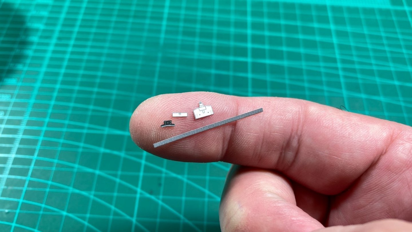
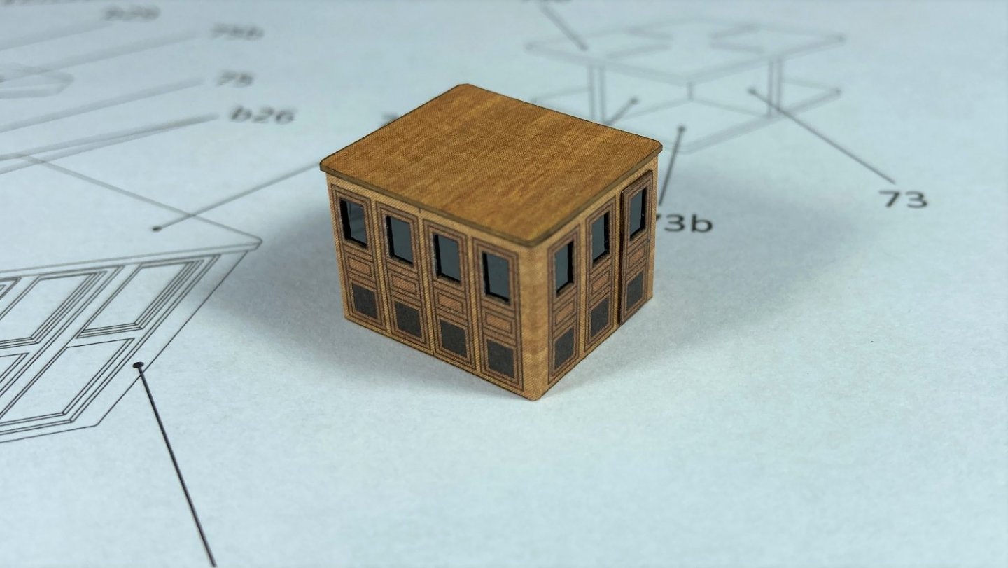
Hi all, Small bit of progress. I made one of the deck houses. Only the one picture as it was more for the YouTube video. Cheers Slog
- 13 replies
-
- 7
-
-
- Dom Bumagi
- Admiral Nakhimov
- (and 1 more)
-
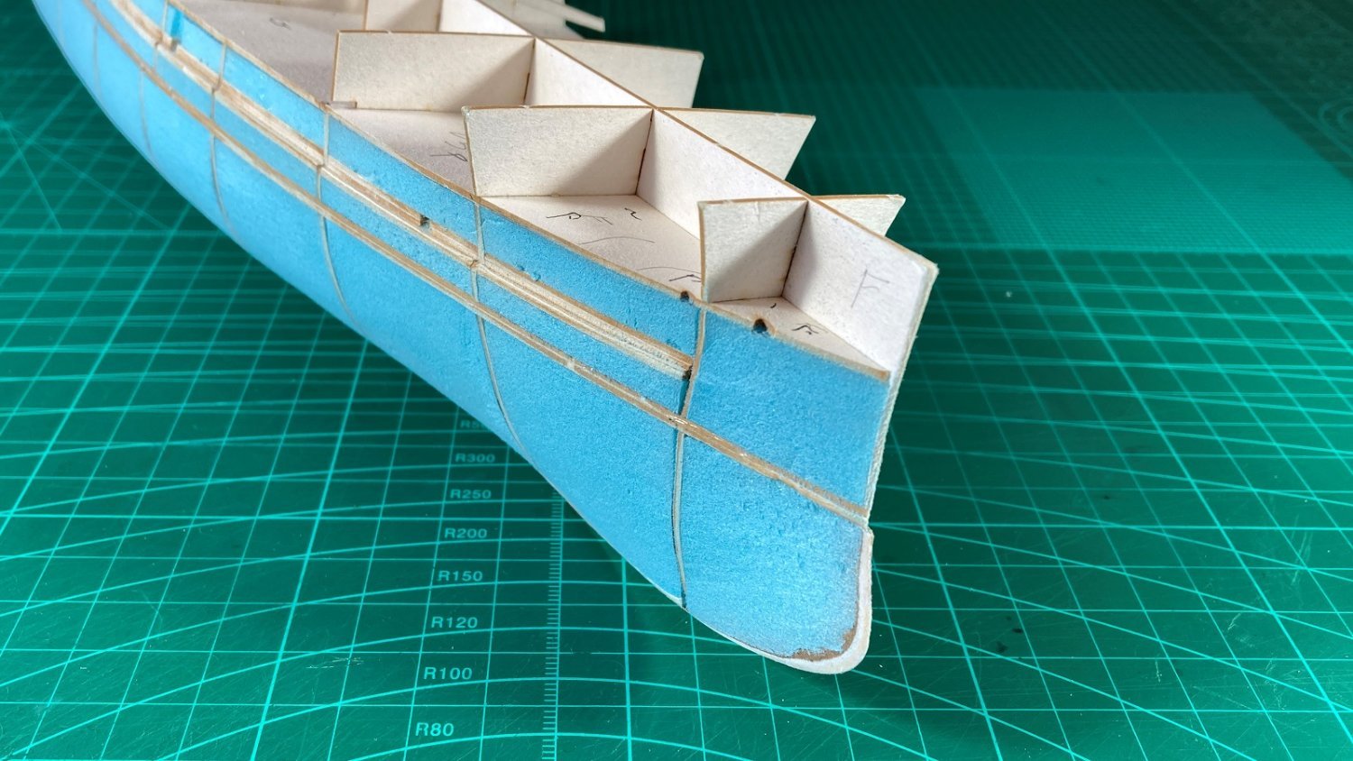
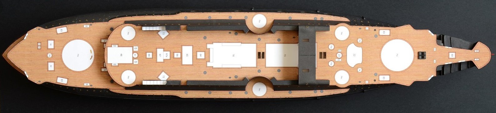
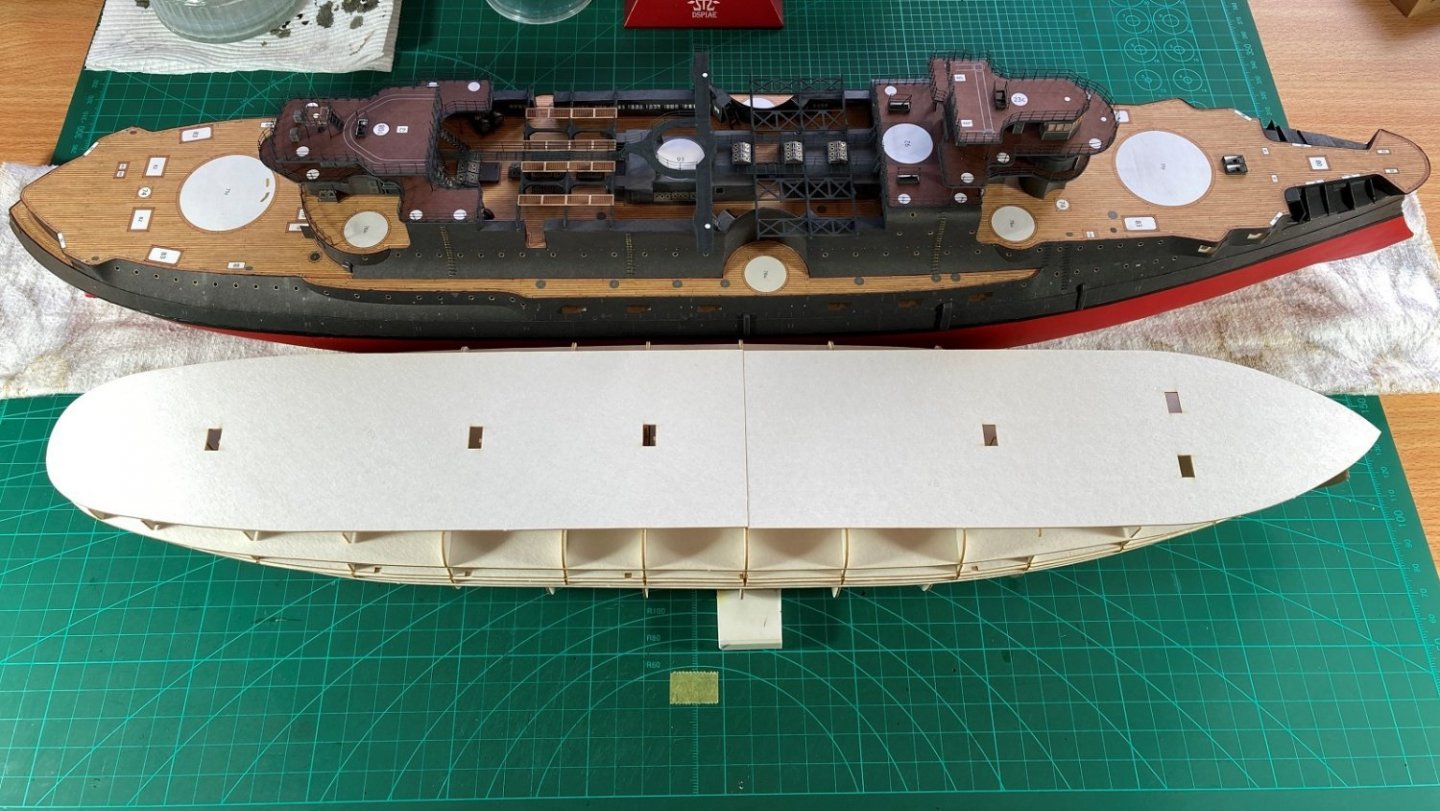
Hi all, Working on the upper hull now. All the parts cut out and cleaned up. The bulk of the upper hull glued up. A few issues were found, which included incorrect deck numbering on the diagrams but the biggest issue was a number of slots for the locating tabs were in the wrong position. I double checked the laser cut forms against the templates to see if they were different but as guessed they matched the templates so the issue has been copied through. Using the paper (linoleum coloured) gun deck, I determined where the slots should be and after incorrectly making 3 new slots in the vertical spine I cut correct new ones in the horizontal base deck. The upper gun deck halves needed some of the slots widened as they were slightly off position also. I stopped at this point as there are a considerable number of smaller components to attach along the sides and for the stern admirals walk but the diagrams don’t show them but should become clear the time hull skins go on. The upper hull temporary placed on the lower hull for an idea of shape and size of the hull. A side-by-side size comparison of Admiral Nakhimov and Borodino. The Admiral Nakhimov is a bit shorter and only slightly narrower than Borodino. It does have a relatively deep hull though where both main decks are pretty much same height. The associated video. Moving forward, I will concentrate on other deck structures and components whilst working on the hull filling and skinning in the background. Cheers Slog


- 13 replies
-
- 7
-
-
- Dom Bumagi
- Admiral Nakhimov
- (and 1 more)
-
I haven't visited this section of the form until recently so missed this log. Will be following from now on. Looking great. Cheers Slog
-
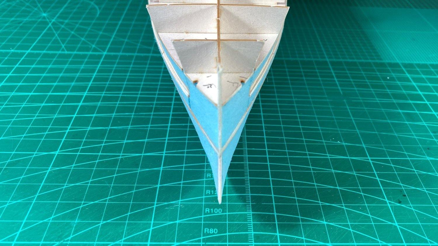
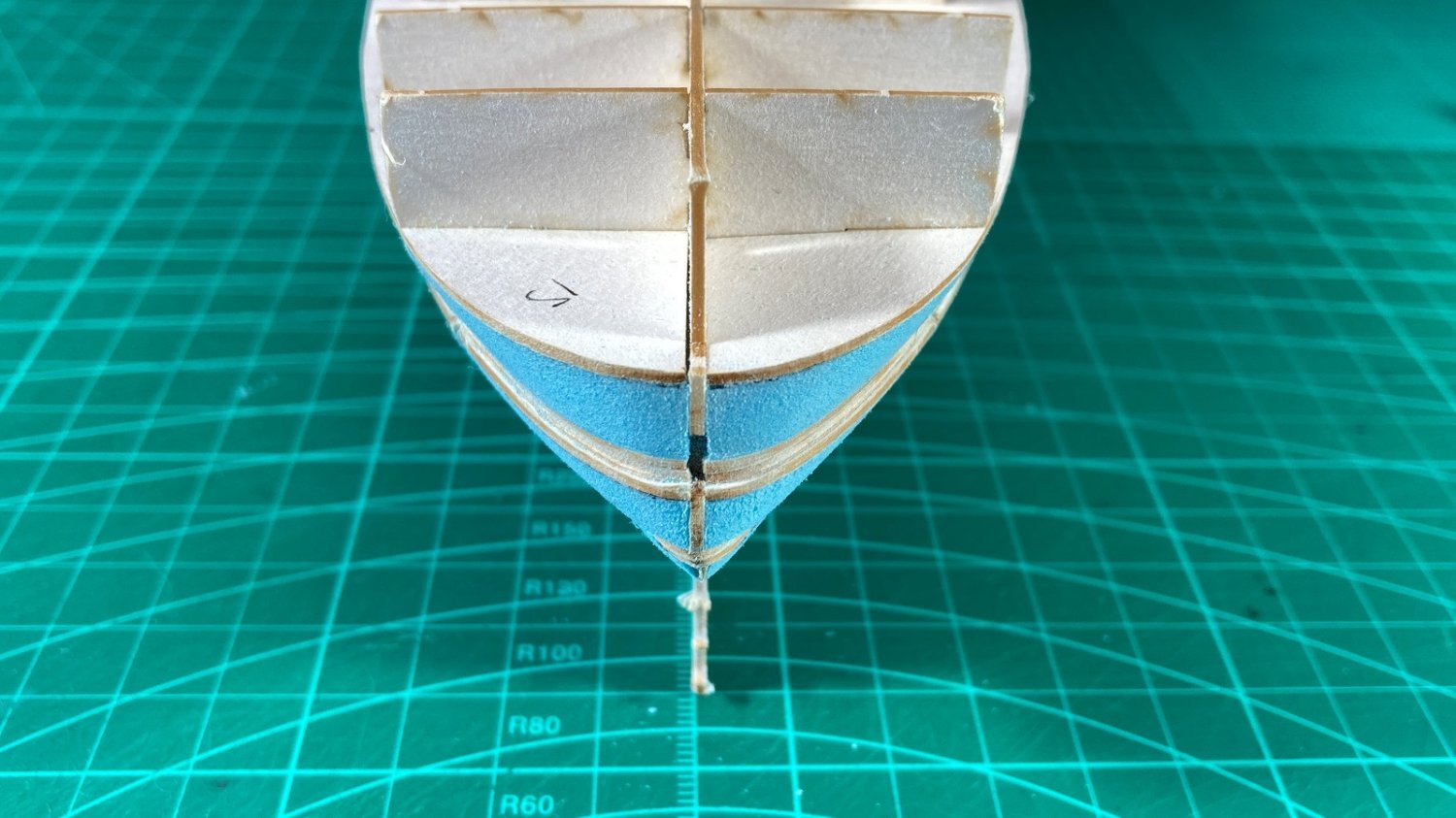
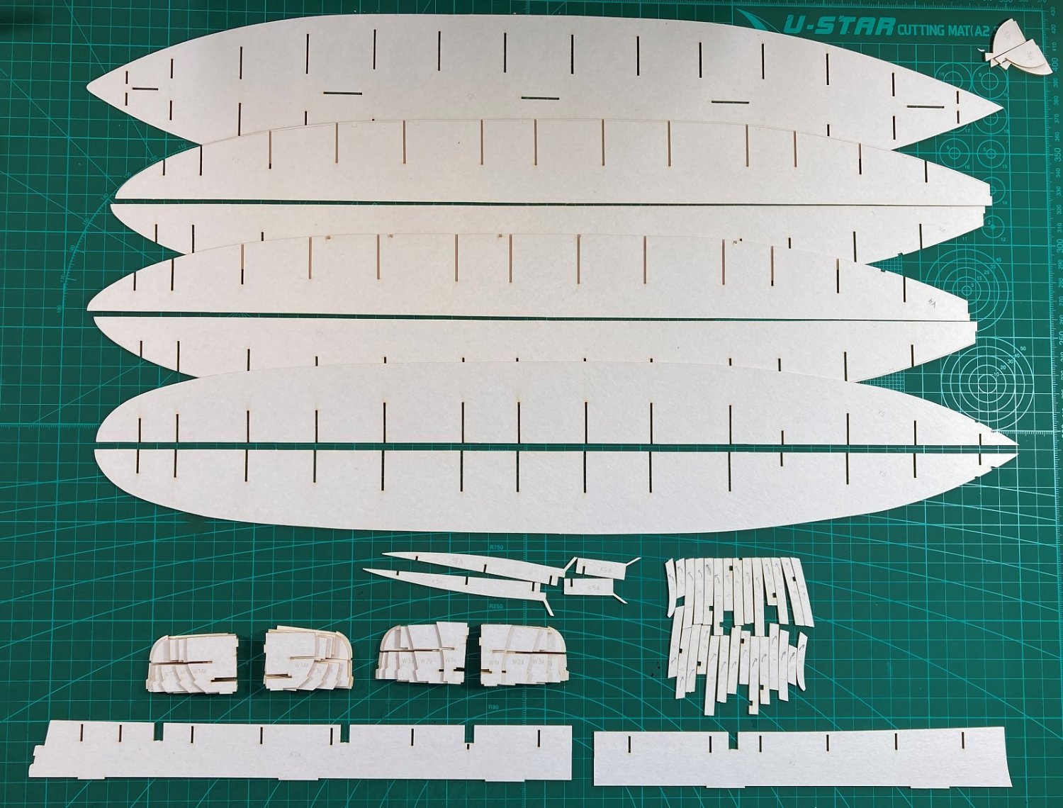
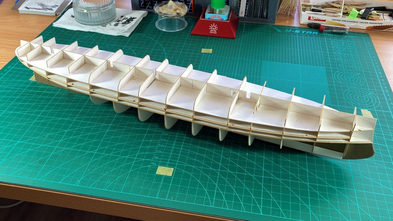
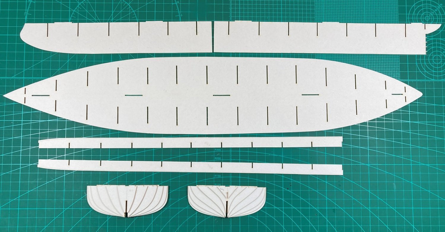
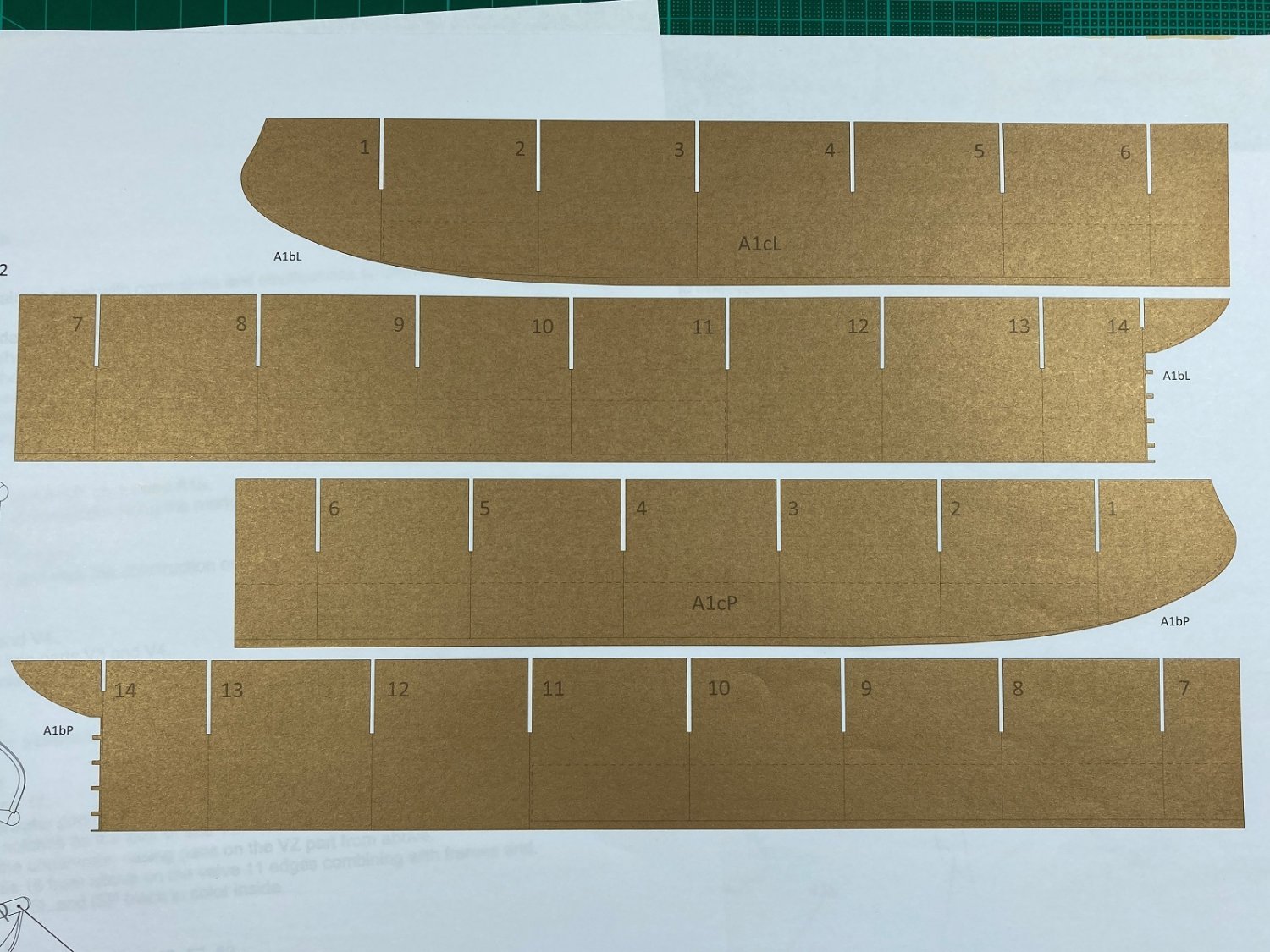
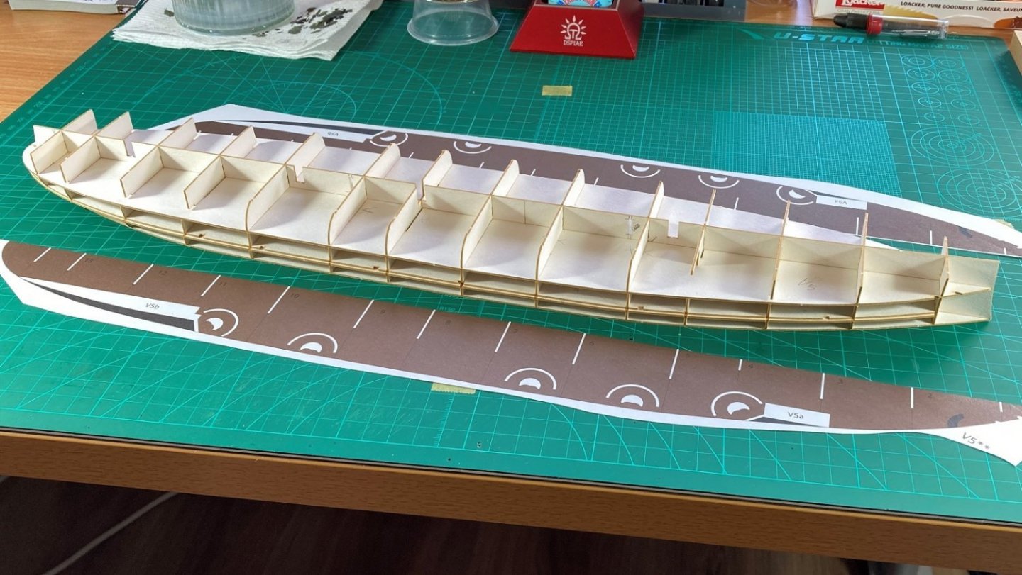
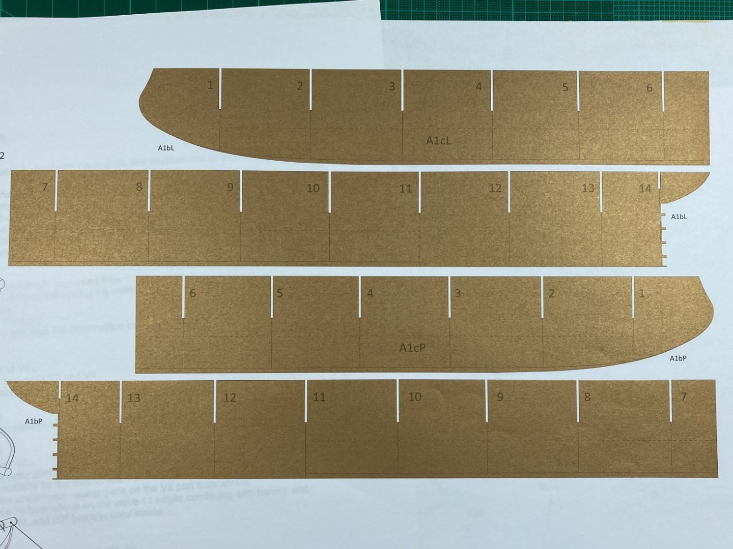
Hi all, Thanks for the likes and Chris’s nice comment. I have made a small start with the lower hull forms. Here they are cut out ready to go. The bulkheads glued to the deck. When I dry fitted the centre spine to the bulks there was a fair bit of play, with the slits in the bulkheads appearing to be oversize. After translating the notes it turned out I needed to skin the centre spine with the gold coloured paper. These were printed on thin paper but when attached to both sides of the spine it was perfect fit in the bulkhead slits. The gold coloured skins were needed as the keel extends down past the hull and is visible, but only this small section a few millimetres tall is seen. Lower hull glued up. Associated YouTube video. I had hoped to do the upper hull at the same time/posting but there are some irregularities that need to be addressed. A bit disappointing but nothing major and will do that for the next part. Cheers Slog

- 13 replies
-
- 10
-
-
- Dom Bumagi
- Admiral Nakhimov
- (and 1 more)
-
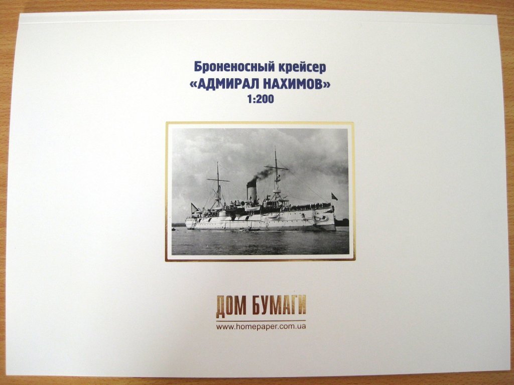
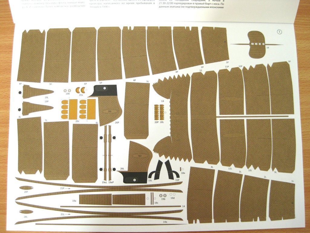
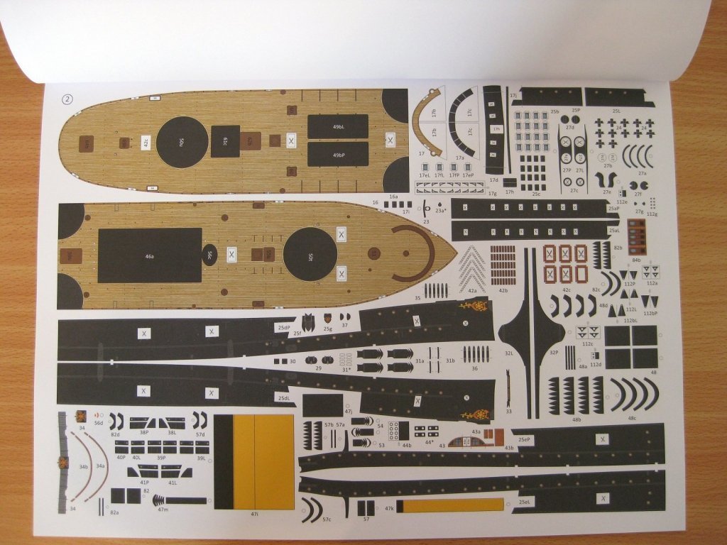
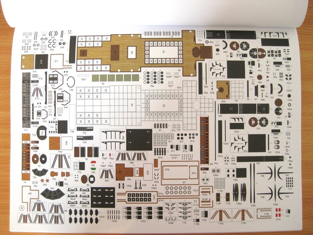
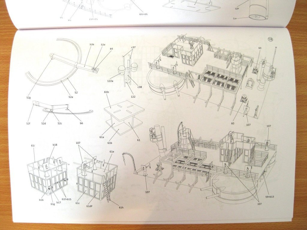
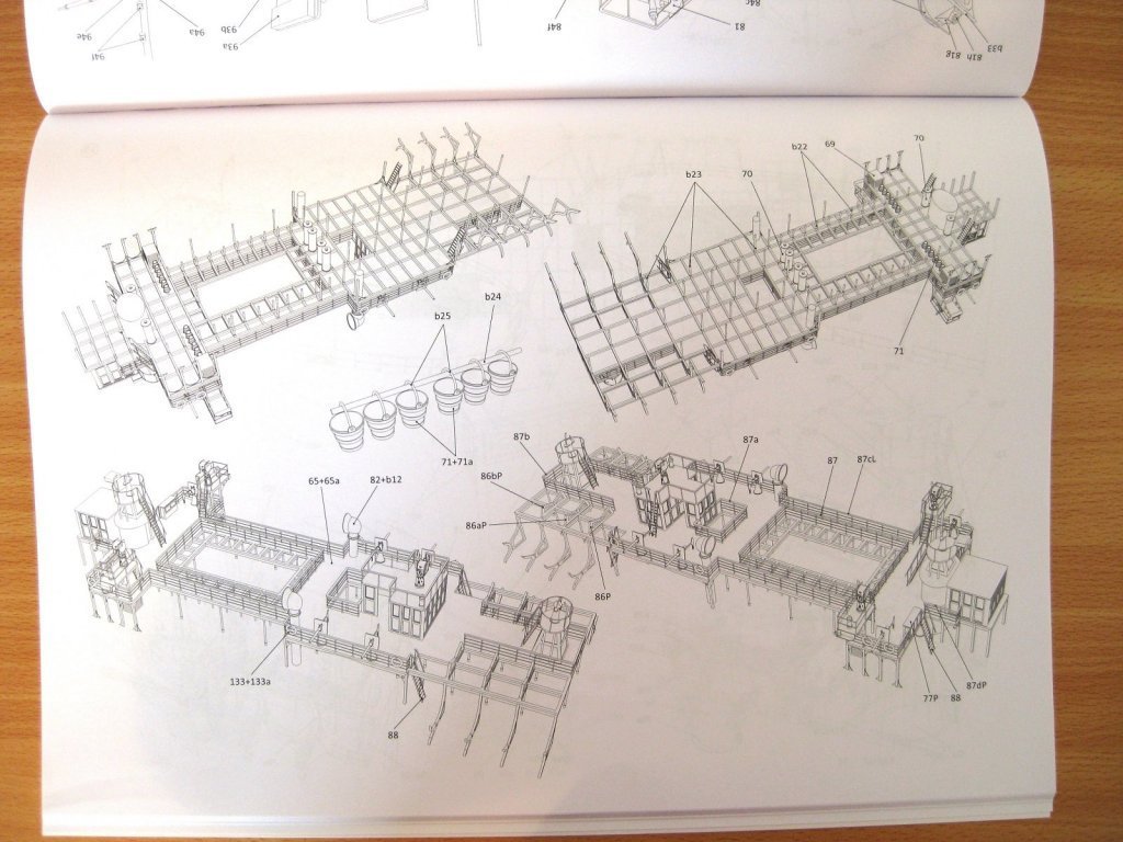
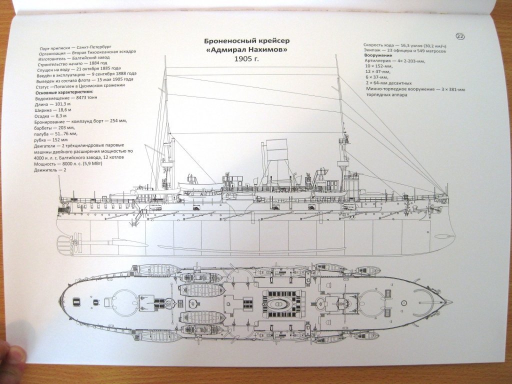
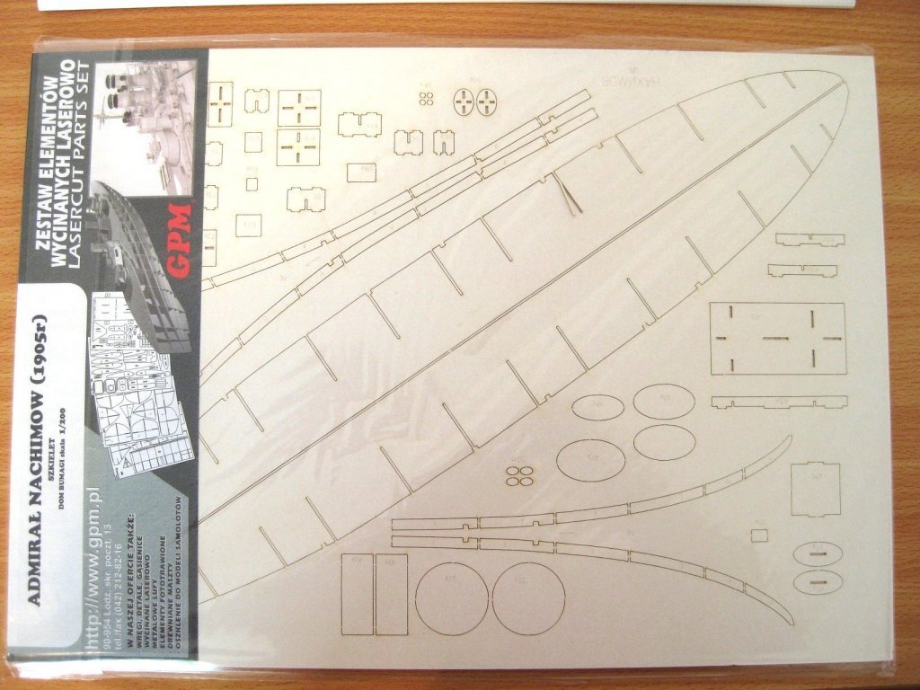
Hi, Welcome to the start of my build log of Admiral Nakhimov. This is an armoured cruiser which took part in and was sunk at the Battle of Tsushima. For those of you interested in her here is a link to the Wikipedia page. https://en.wikipedia.org/wiki/Russian_armoured_cruiser_Admiral_Nakhimov Admiral Nakhimov was another of those kits which I hadn’t noticed before but I came across a review of it many years ago and found her to be such an interesting shape and construction and after discovering her participation at the Battle of Tsushima was added to the stash. I believe this is one of Dom Bumagi’s newer kits as the front cover has changed design to show a smaller picture (in this case a real photo) surrounded by a large border. This is more conventionally presented as an A3 book, bound along the top long edge. There are 7 pages of parts and again some sheets have full reverse colour and others have selective reverse colouring. The lower hull has a shiny metallic finish. There are a lot of nice parts and colours on this ship like the raised decks and different coloured cabins. There are 5 thin pages of templates for the underlying skeleton and also includes the gun deck which appears to depict linoleum. There is a single thin sheet for all the ‘ironwork’ details as well as the rollable gun barrels etc. There are 7 double sided sheets of assembly diagrams and these are line drawings as opposed to renders and I must admit I think these will be clearer to read than renders which I was excited about for Borodino. The last page shows a plan and profile view of the ship. I obtained the laser cut forms but these supply only 5 sheets of the thicker underlying forms with no thin sheets for detail parts. I have also done a YouTube video of the kit review Cheers Slog
- 13 replies
-
- 12
-
-
-
- Dom Bumagi
- Admiral Nakhimov
- (and 1 more)
-
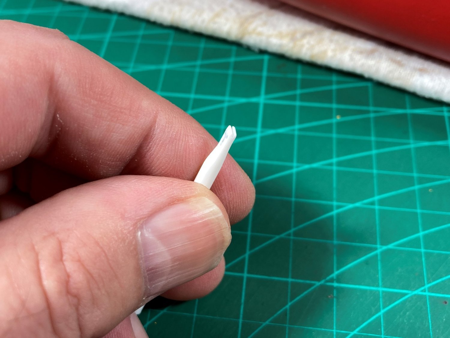
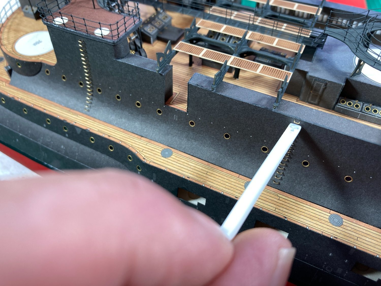
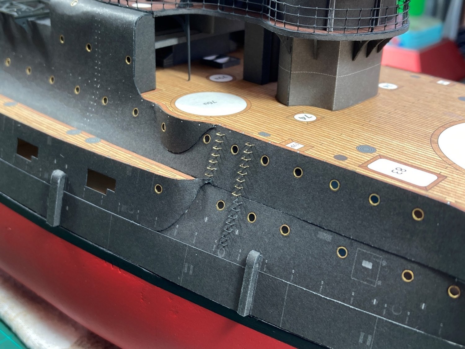
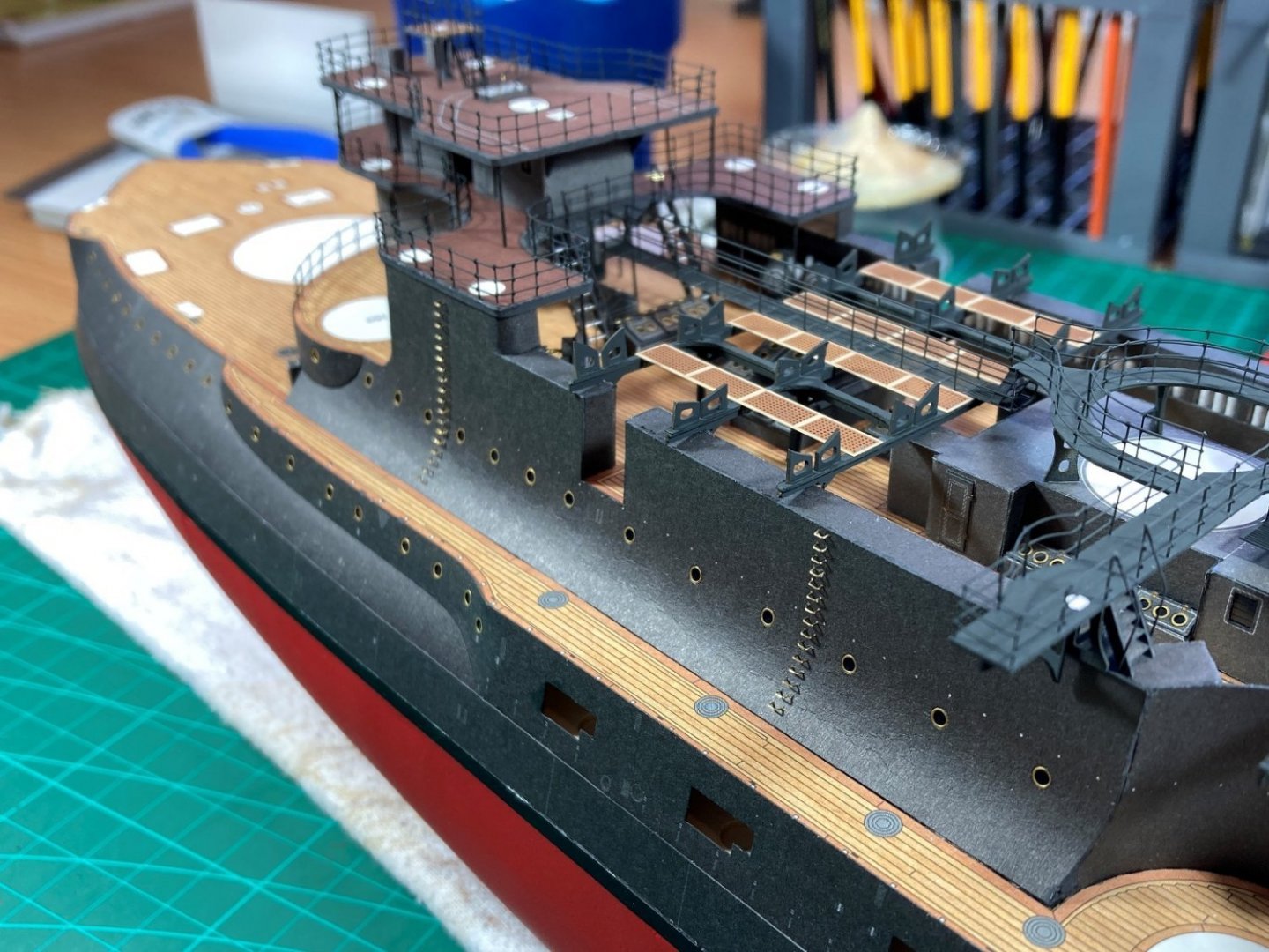
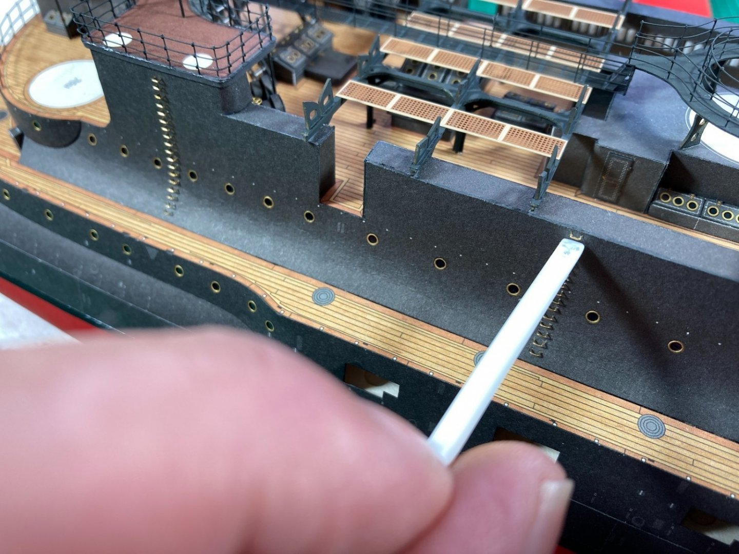
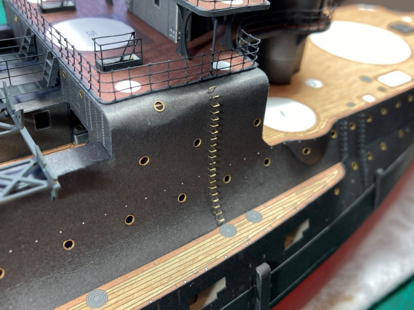
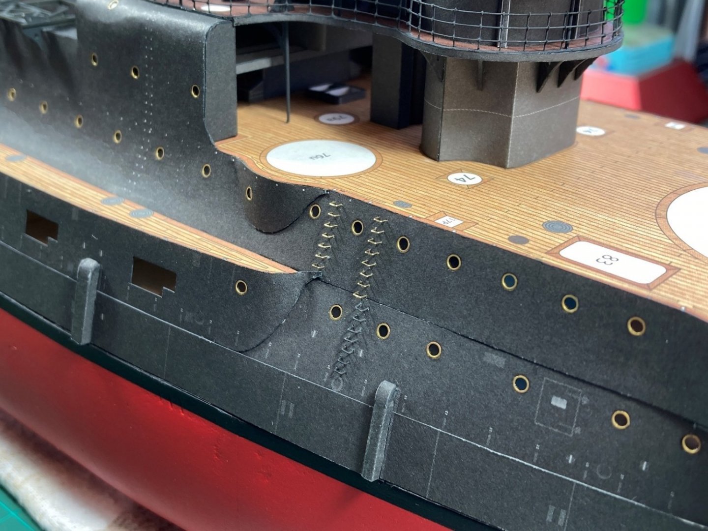
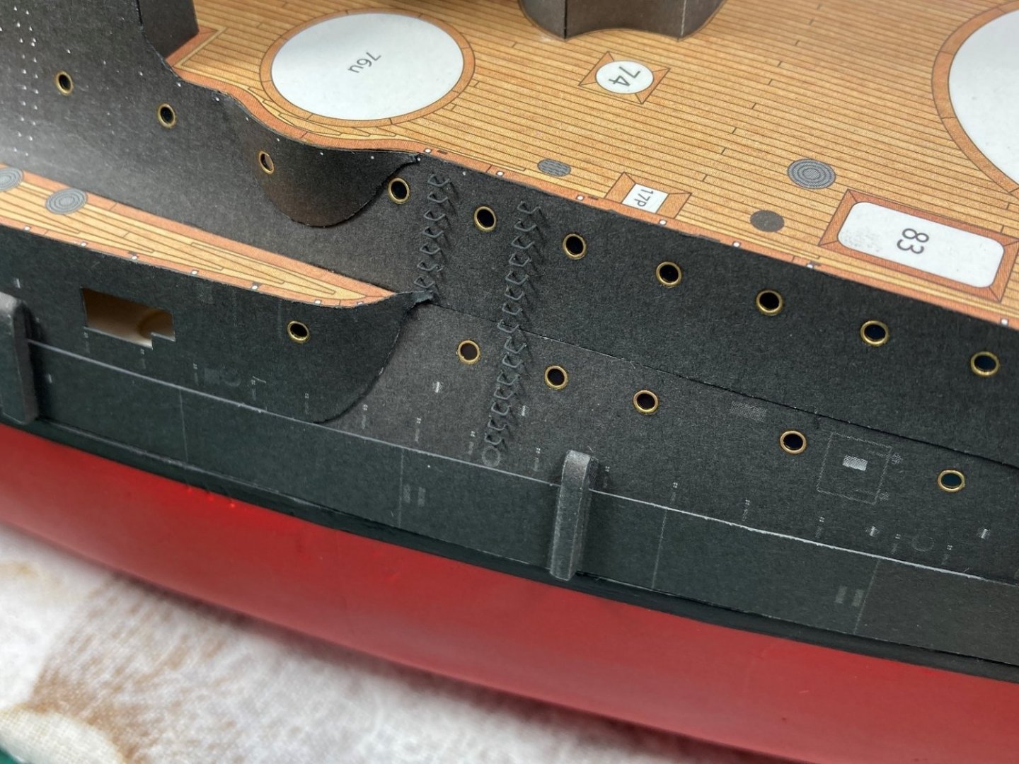
Hi All, I previously made a post in the “Hull fittings” section of the forum on how I do the steps/ladders on the side of the hull, which you may have seen but I'll link below and expand on later as some lessons learned from that changed how I did the remainder. New Content. After doing the section covered above and in the video, I found I needed to change the method for consistently setting the gap for the step distance from the hull as my usual method was too clumsy due to step location and the shape of the hull. After a bit of brain storming I came up with and made a ‘setting’ tool made from half round Evergreen styrene strip. I cut/scraped/sanded a recess into the end of one styrene strip. Then gluing another strip to it left a slot in the end big enough for the 0.2mm wire steps shown above. I needed to scallop the styrene on both sides of the gap so it fitted between the closely placed steps. As the recess was made deeper than required I would install a step, ‘set it’ then sand the end of the tool back a bit and continue doing this until the correct depth of insertion was reached. The process was then to insert all the steps roughly in place for a run of steps then use the ‘setting’ tool to push each step in to its final depth. When the tool touches the hull, it is at the correct depth of 0.5mm (gap). I would work down a section of steps before locking in place with glue. Some photos of all 154 hull steps now fitted and glued in place. Using the ‘setting’ tool was very quick and got a more consistent finish from the method used in the video. I will paint them black once I install the horizontal hand rails that run along the sides of the hull. Cheers Slog

- 244 replies
-
- 11
-
-
- borodino
- dom bumagi
- (and 1 more)
-
Yeah, I posted links back last April I think when I did the 47mm hotchkiss deck guns. The first 3 aren’t that great as trying to find style etc. I made another Borodino video last month on the hull steps but didn’t post in this log yet as was waiting for more progress but did post it in the hull fittings section of the forum. I have started on Admiral Nakimov also and filmed kit review and started on the hull but haven’t posted on YouTube or here yet as lately have no spare time to model but should be posting something here and YouTube this weekend…maybe
- 244 replies
-
- 3
-
-
- borodino
- dom bumagi
- (and 1 more)
-
Hi RN, Good to see progress on this. Yeah I made tabs from the waste laser cut forms to place in the slots to align the decks but didn’t glue them in. I can’t remember but I think final positioning was with the Mk 1 eyeball to get even spaces all round.
- 31 replies
-
- 4
-
-
- Borodino
- Dom Bumagi
- (and 1 more)
-
The discolouration is known by deluxe and something they are looking into. I don’t want to highjack Chris’s thread but know he, like me, is looking for the holy grail of glues but I recently purchased Ammo by MiG Ultra glue for photo etch, canopies etc which is a thick acrylic glue which I may try on my paper build to see.
-
Hi, I have used this and mentioned it in my build log. It is very milky and it grabbed and set very quickly which made it ideal for gluing up smaller parts but didn't really give any wiggle room. I applied it with a small brush. It also was good in gluing other materials to paper such as brass. I stopped using it when it turned to a chocolate milk colour in the bottle over time, but apparently according to the manufacturer this doesn't affect it's performance. However I have still not used it in some time as old dried glue turns brown and crystallised. Doesn't affect where I used it as ideally shouldn't have glue/excess glue visible anyway but something to keep in mind. The already glued parts are still going strong though.
-
A very nice, sharp, clean build. I look forward to your next card model.
- 18 replies
-
- 2
-
-
- card
- World of Paperships
- (and 2 more)
-
Nice work. Your colour matching is exceptional! Would never guess that is painted styrene rod
- 331 replies
-
- 10
-
-
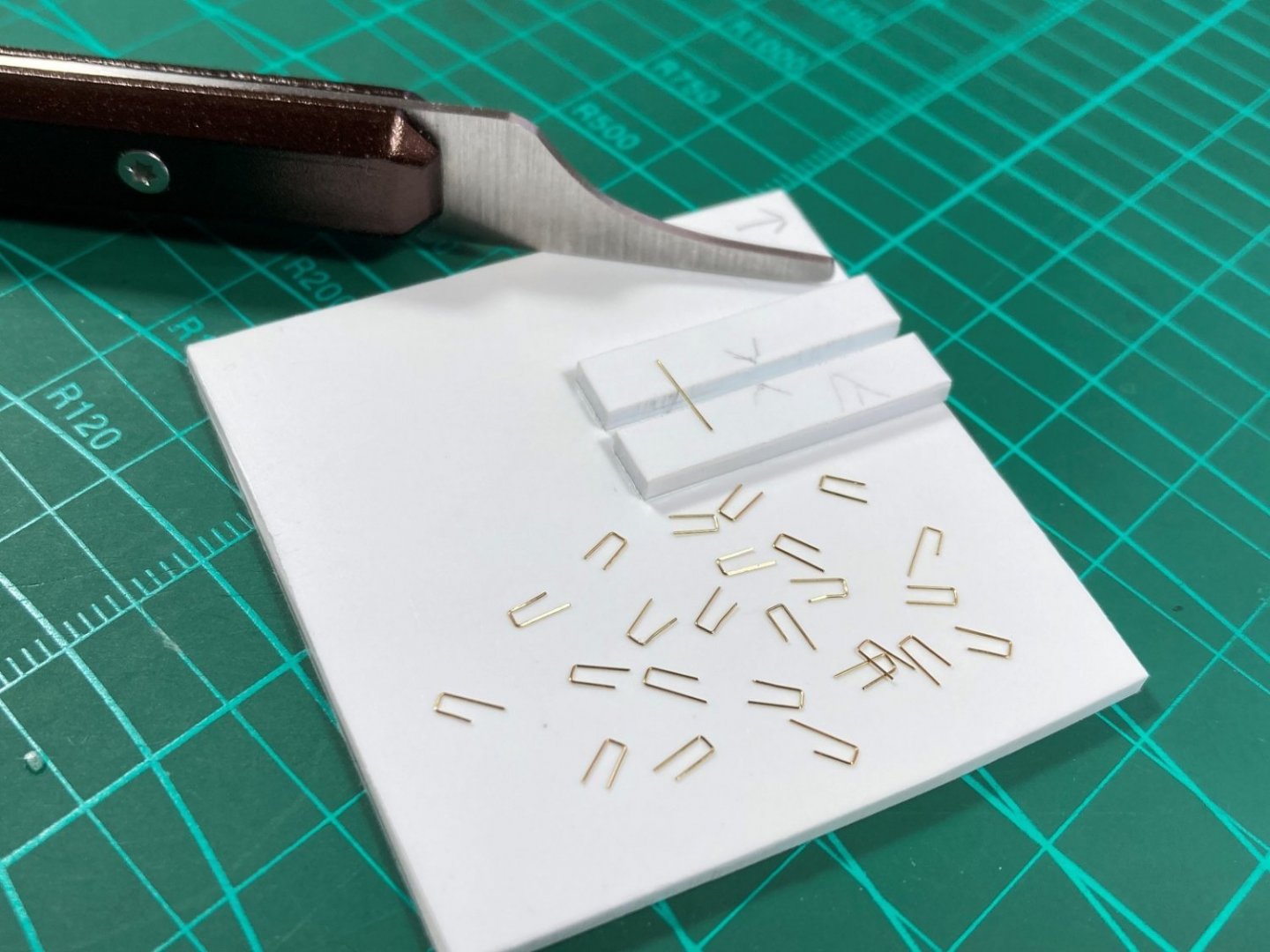
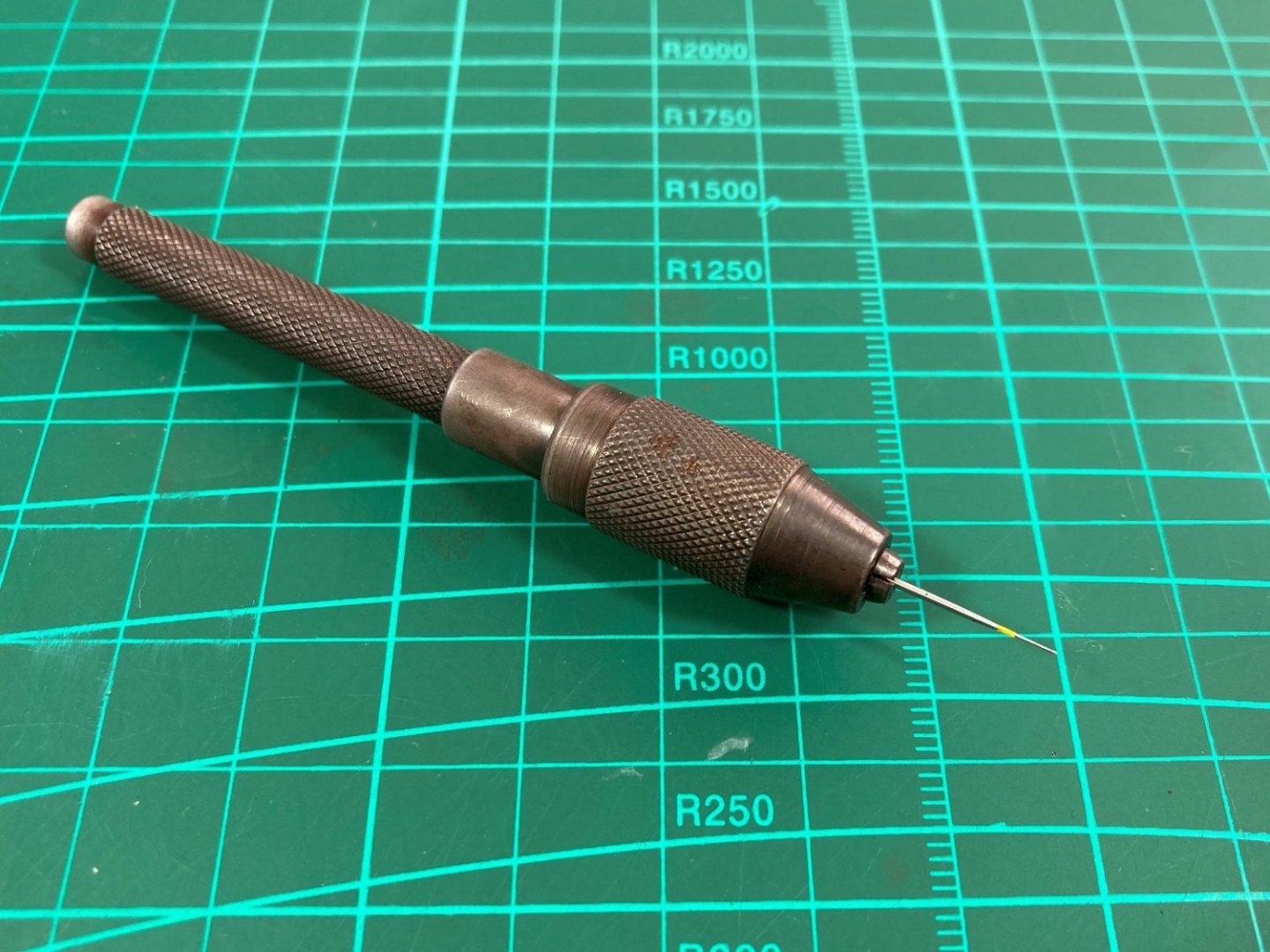
Hi, This is the latest video in my YouTube series I am doing for my build of Borodino, which can also be found in the kit build log section of the forum and shows how I make the steps/step irons/ladders (I believe the correct term is ladder?), which are located all over the hull. First photo shows a simple jig I made out sheet styrene to quickly and consistently fold the 0.2mm brass wire into the correct shape in a single action. The ‘former’ is a seam scraper for plastic models from Citadel but the width of the blade is the perfect size for steps. This shows a ground down sewing needle for making the locating holes in the paper as the 0.2mm brass wire isn’t stiff enough to pierce the paper even if pin pricking beforehand. The yellow paint marks the 0.2mm diameter on the needle to match the wire diameter so I don’t go in to far, over enlarging the holes. Previously I used to put the needle in the Proxxon rotary tool and use the lowest speed to make the holes but trying it out for this video discovered it works just fine in a pin vice, which is far more controllable for this purpose. The 0.2mm brass wire steps located in the hull and glued with diluted PVA ready for painting. The finished steps painted up…only another 132 to go! I used watercolours to paint the steps as it is a fairly close match to the paper which isn’t fully black. And of course, the video link; Cheers Slog
- 1 reply
-
- 10
-