rwiederrich
-
Posts
5,520 -
Joined
-
Last visited
Content Type
Profiles
Forums
Gallery
Events
Everything posted by rwiederrich
-
Yes...you want an even consistent look.....not a look of dilapidation and leaching....that these pictures also represent. Unless, that's what you are looking for....then you need to treat your entire vessel in like manner. Weathering her consistently.
-
Not to be disparing, but I refer you to your own image.....I think your donkey boiler is too small for your arrangement, Unless you are modeling much large derrick pile driver.....?
-
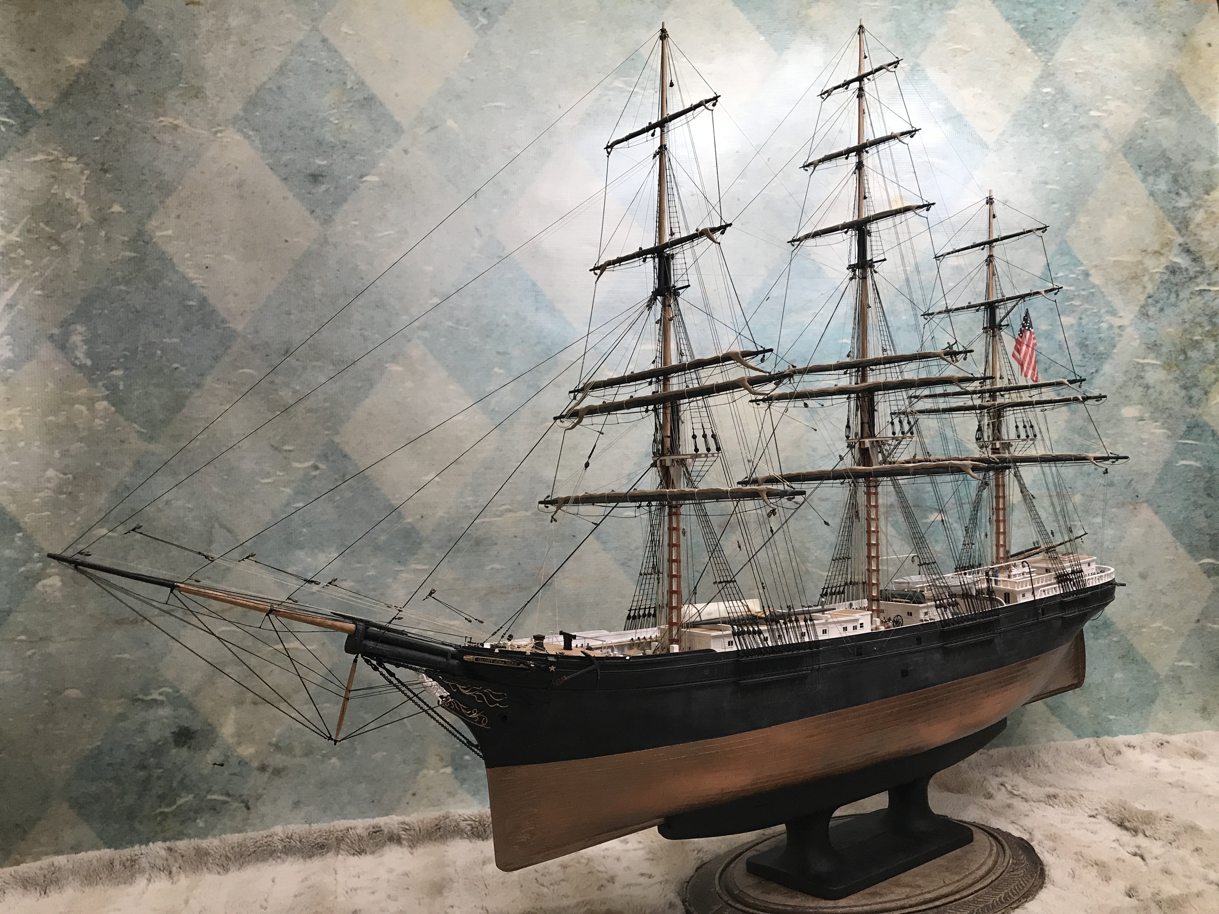
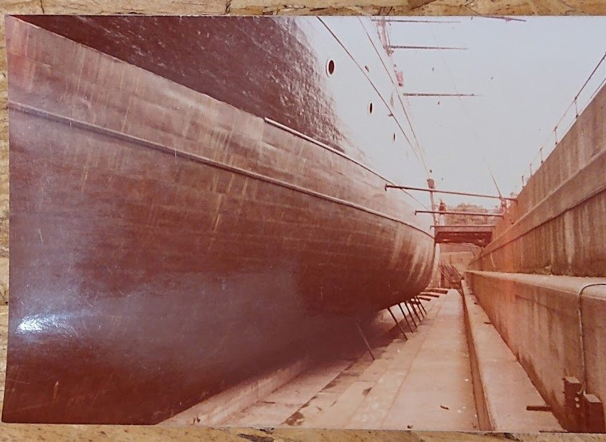
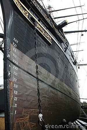
That paint coupled with the shiny copper...really lent itself to the aged muntz I was after. And the paint helps seal the copper to the hull and to each other. I used light coats so the copper itself would kinda shine through but not. Its an interesting effect. I used the old images of Cutty Sark in her drydock long before she was ever burnt and rebuilt. The older picture is a bit faded.
-
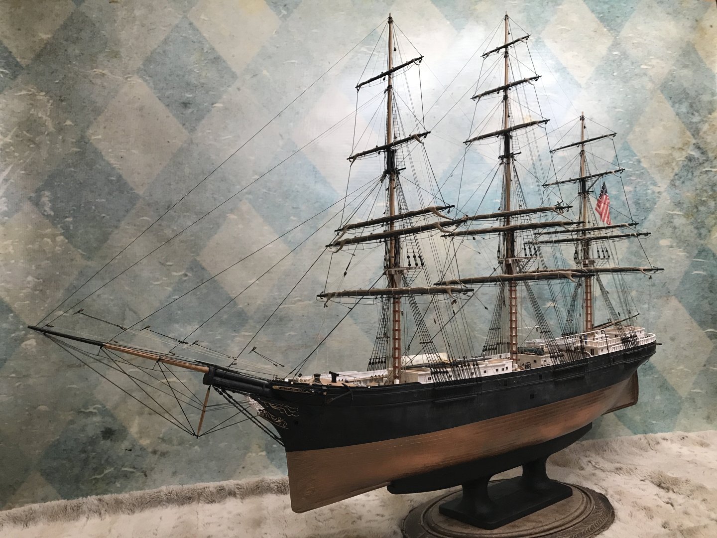
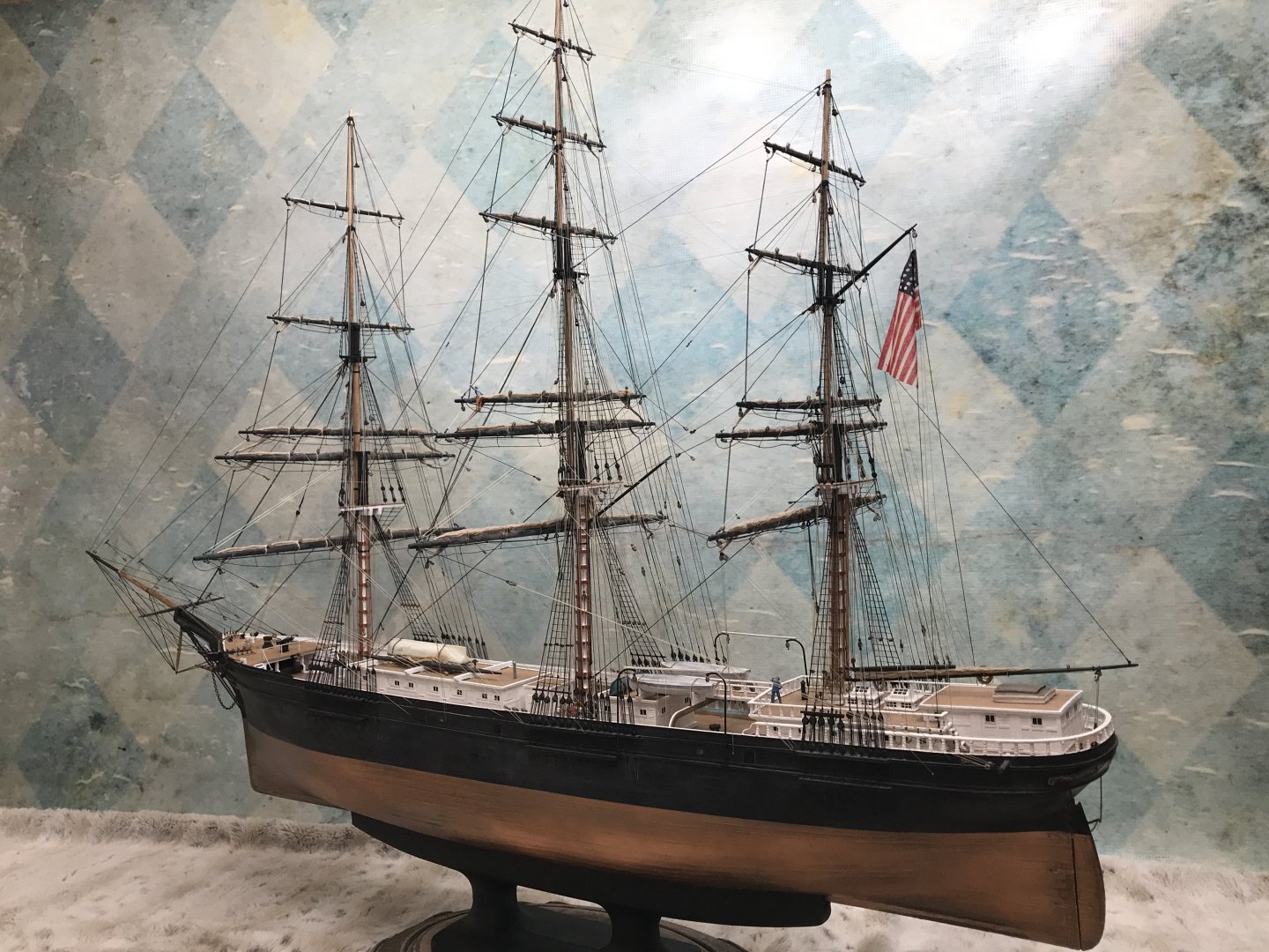
Good night nurse! You’re going at it the hard and technical way. I just spray painted my copper with metallic paint. As I applied it, it mixed with the copper color and took on the look of aged oxidized muntz. Which turns kinda brownish. I liked the result. Rob
-
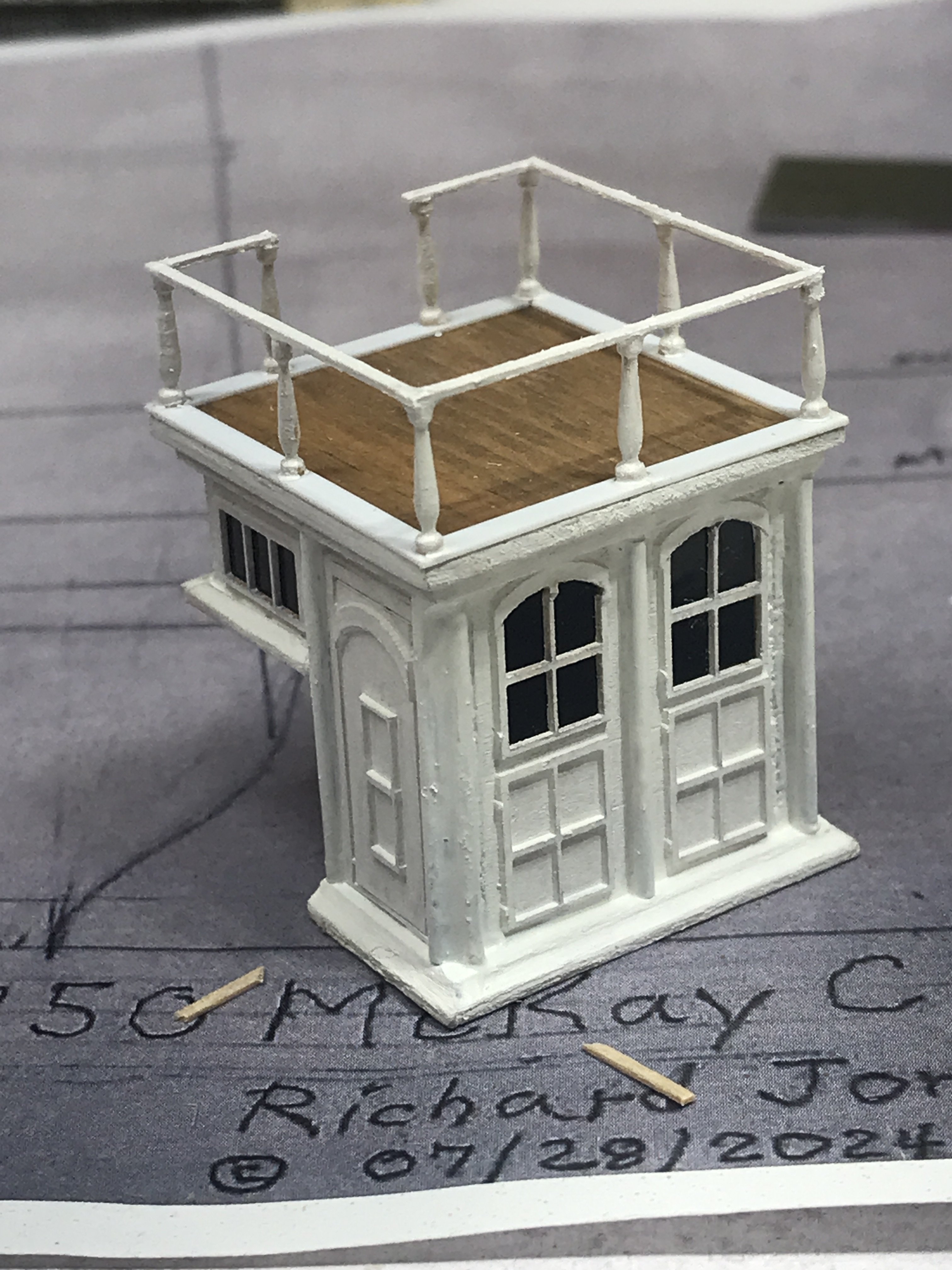
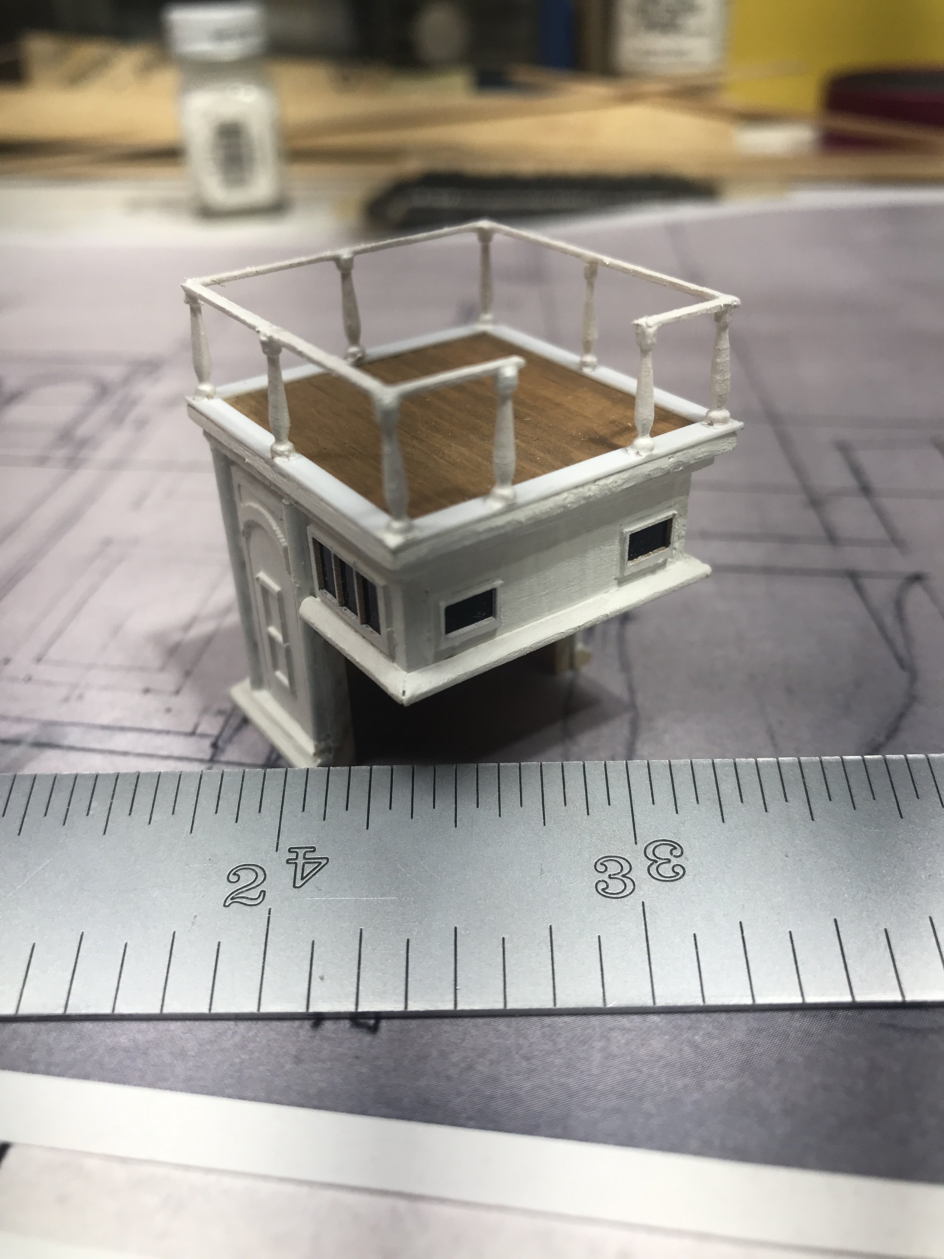
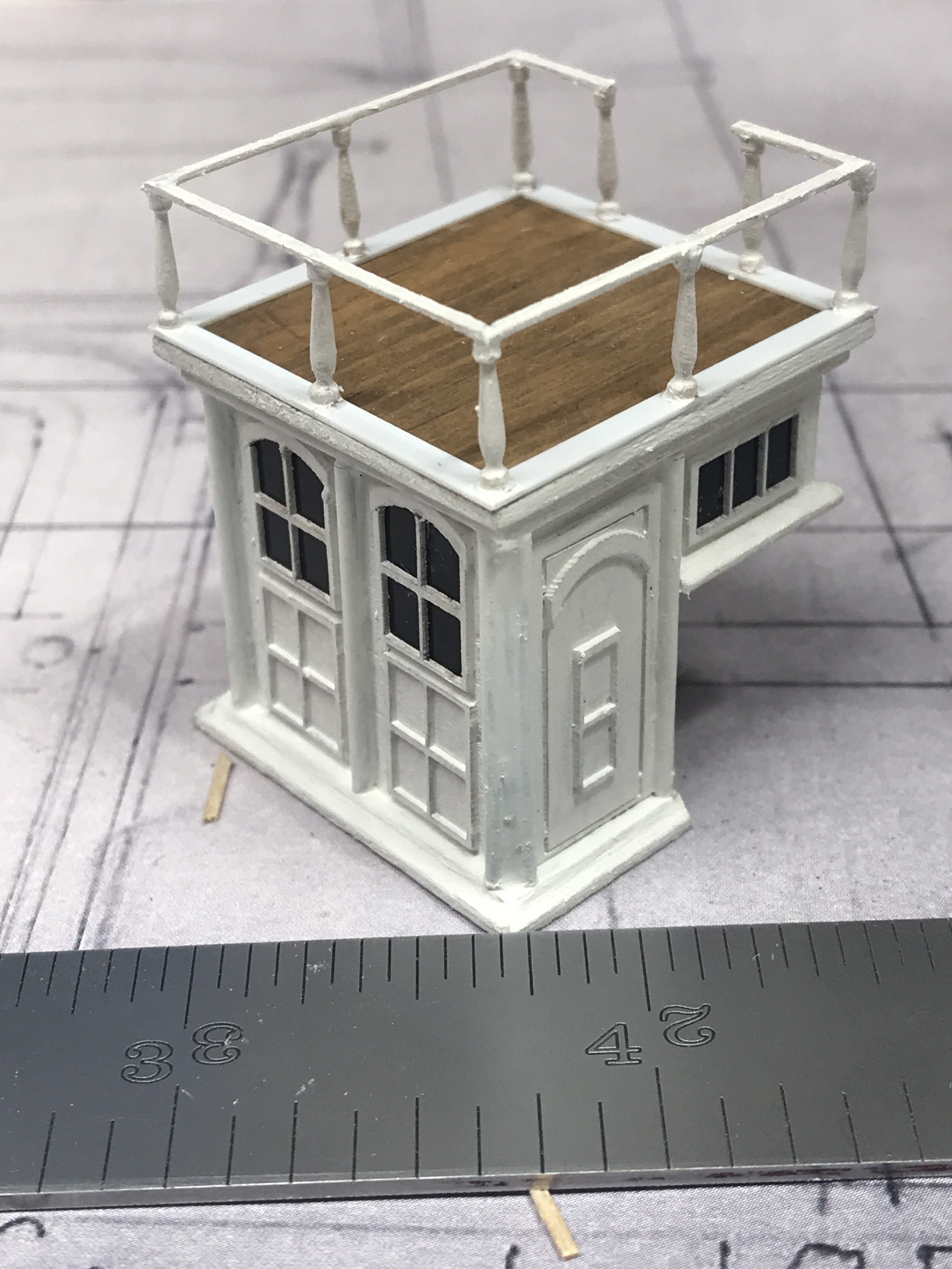
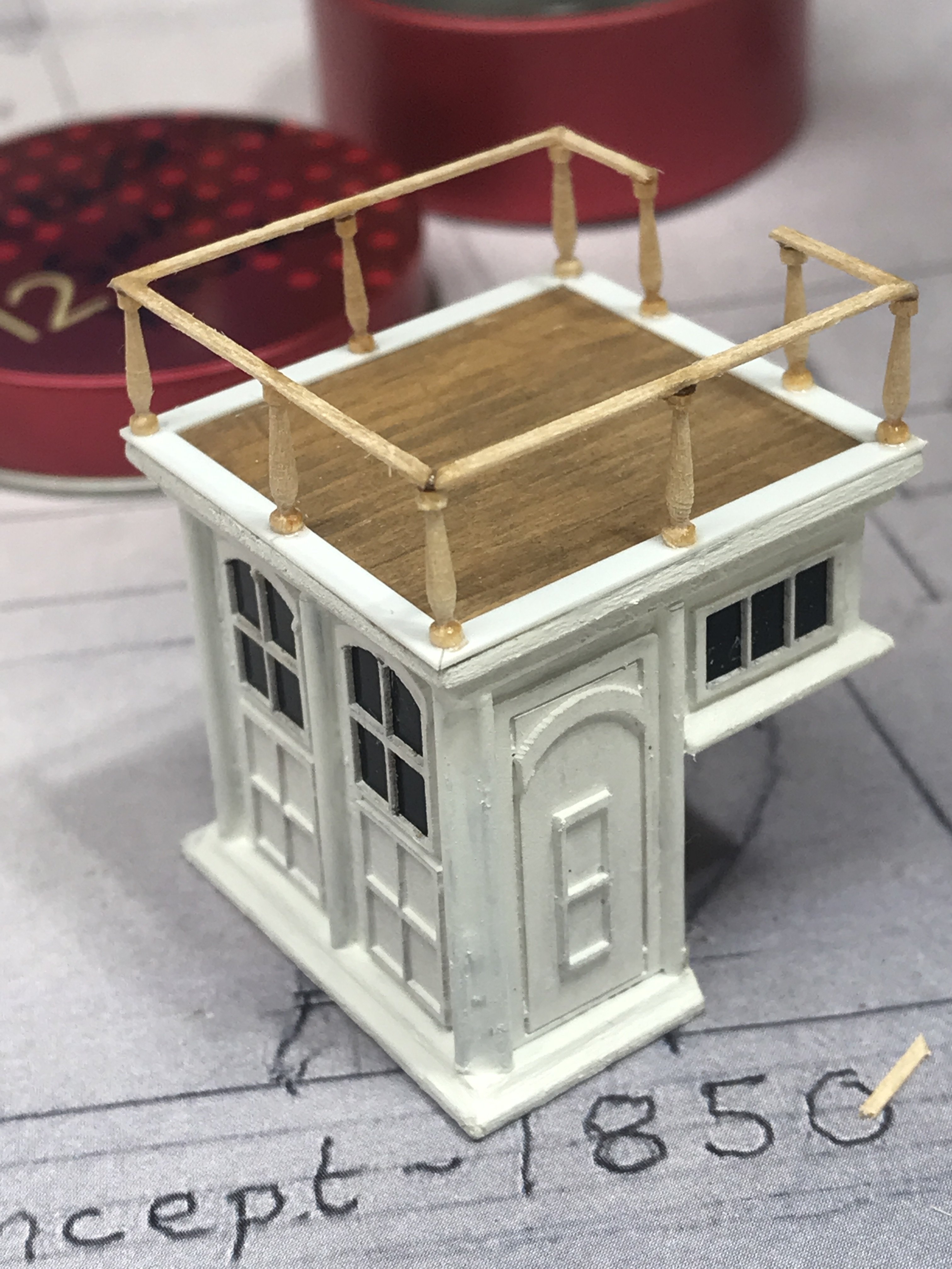
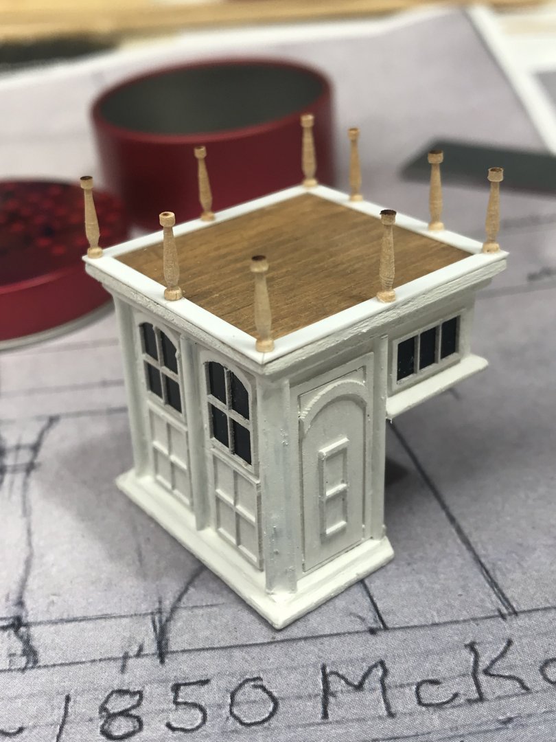
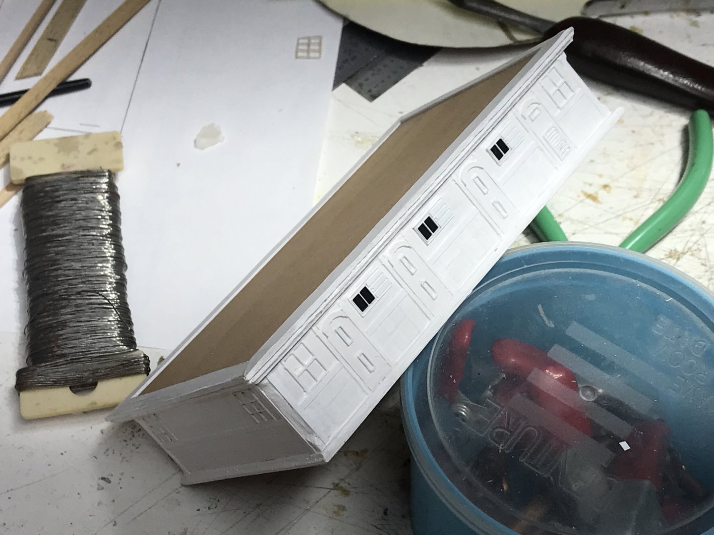
Finally paint and there you go. Of course I’ll add the steps later. I don’t want to break anything that hangs away from the body. The railing is quite fragile all by itself. Rob

-
Railings. Rob

-
Now comes the stanchions. Rob
-
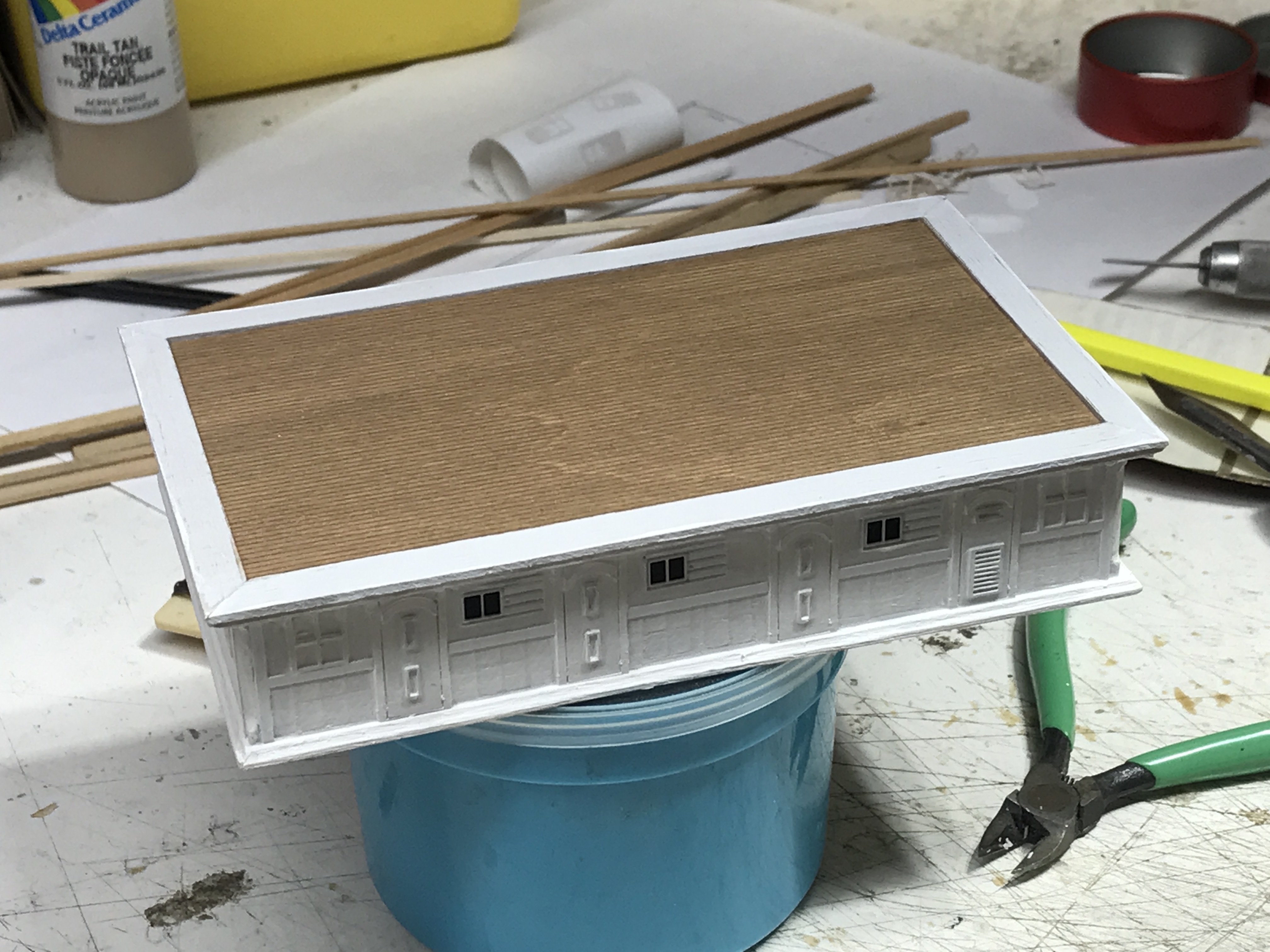
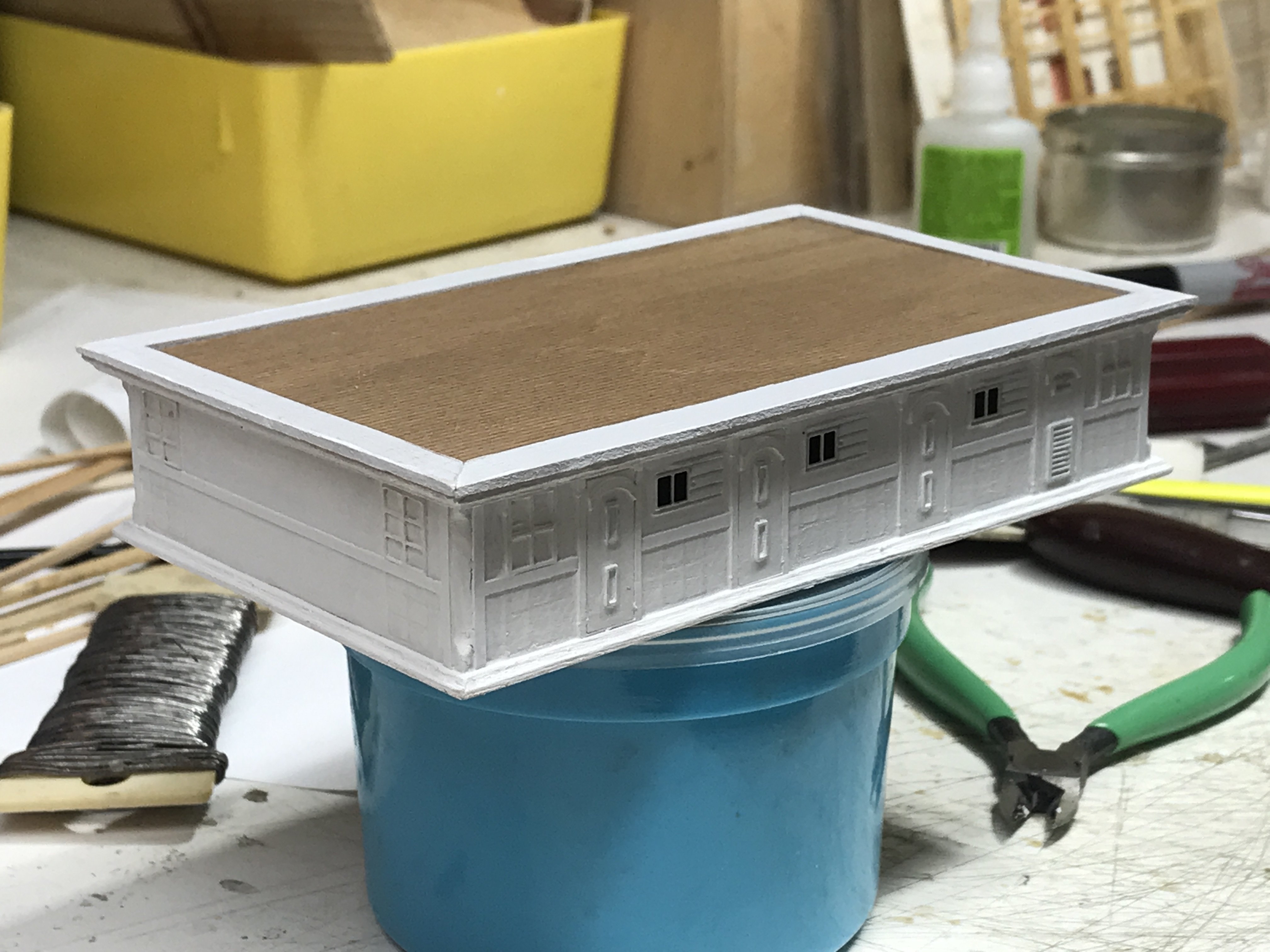
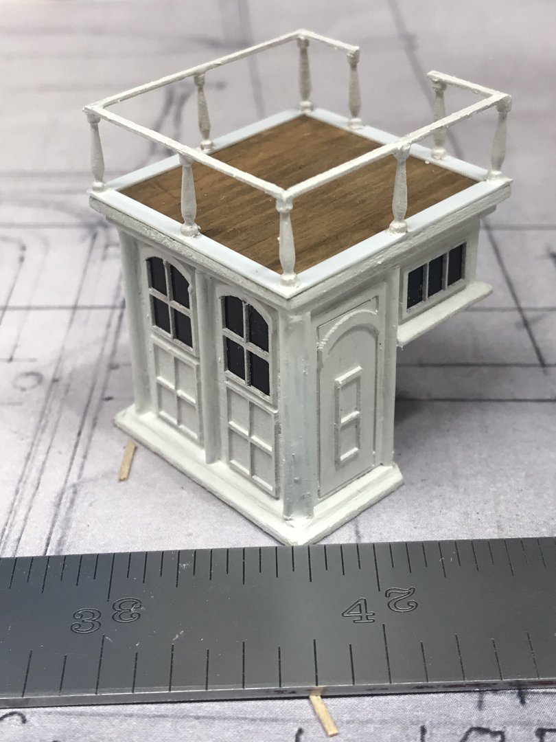
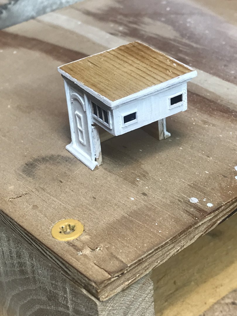
We’ll I worked on the portico and have some progress pics. Stained the top to match the deck and added the aft deck and stanchion trim. Rob
-
I agree with 5 port holes per side in conjunction with 5 flush deck prisms. That shouldn’t be too hard. Rob
-
So from this, you are saying the skylight is 10ft long by 6ft 4 inches wide....meaning that the upper light is only 4ft wide with the addition of 10in seats on either side....rounding it out to 6ft 4in wide.....? Rob
-
Thanks....I considered the idea that this is an entry way...and the aft portico that must have ornate facing windows and pillars. the panel work on its front is reminiscent of the larger carriage houses of McKay's larger clippers , which actually had poop deck cabins. A kind of captain's palace....per se'. Next, I will be adding the stanchion base peripheral trim and stanchions....and possibly the steps and their railing...after I add the exterior deck base trim around the aft end of the portico. Rob
-
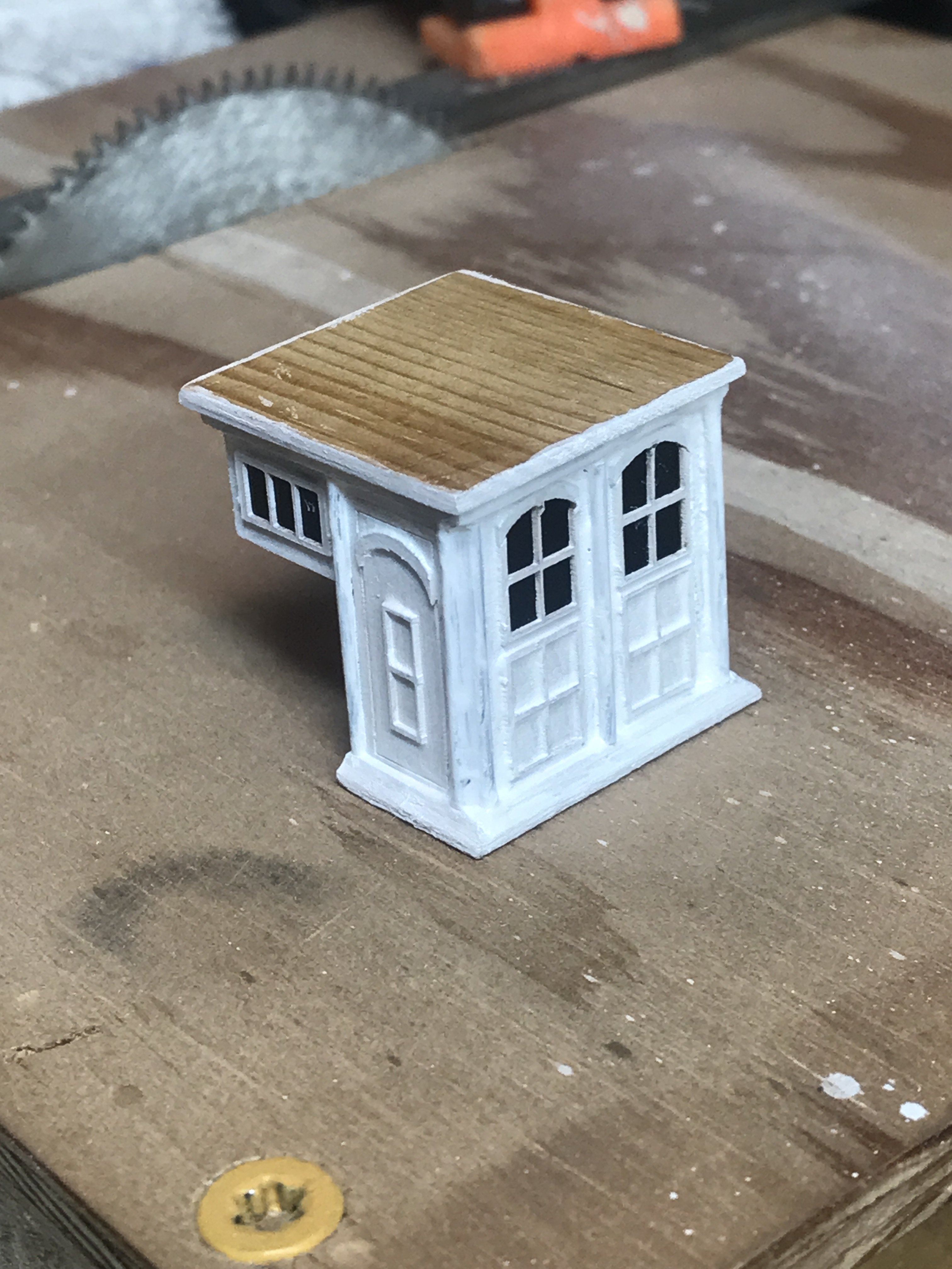
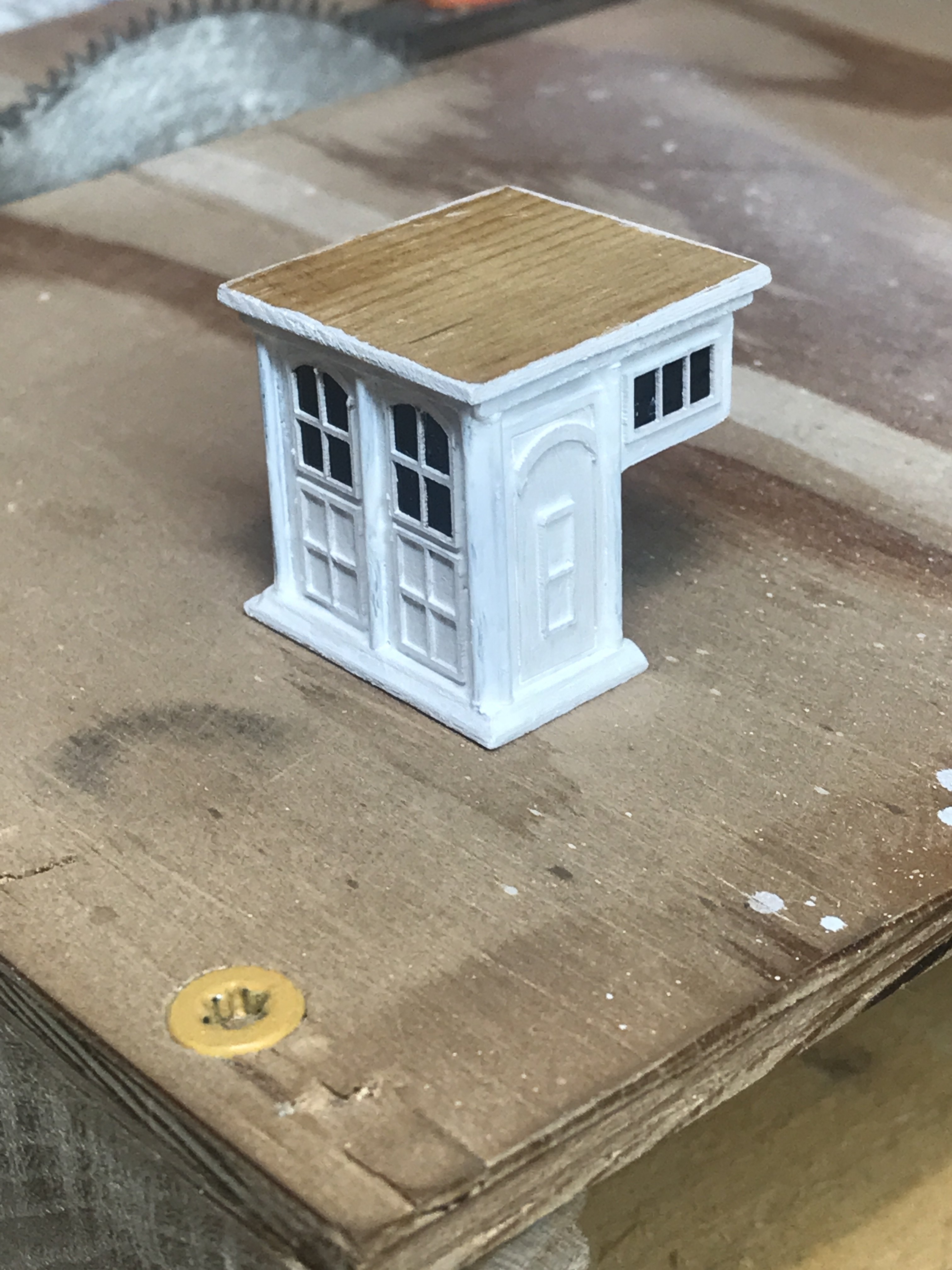
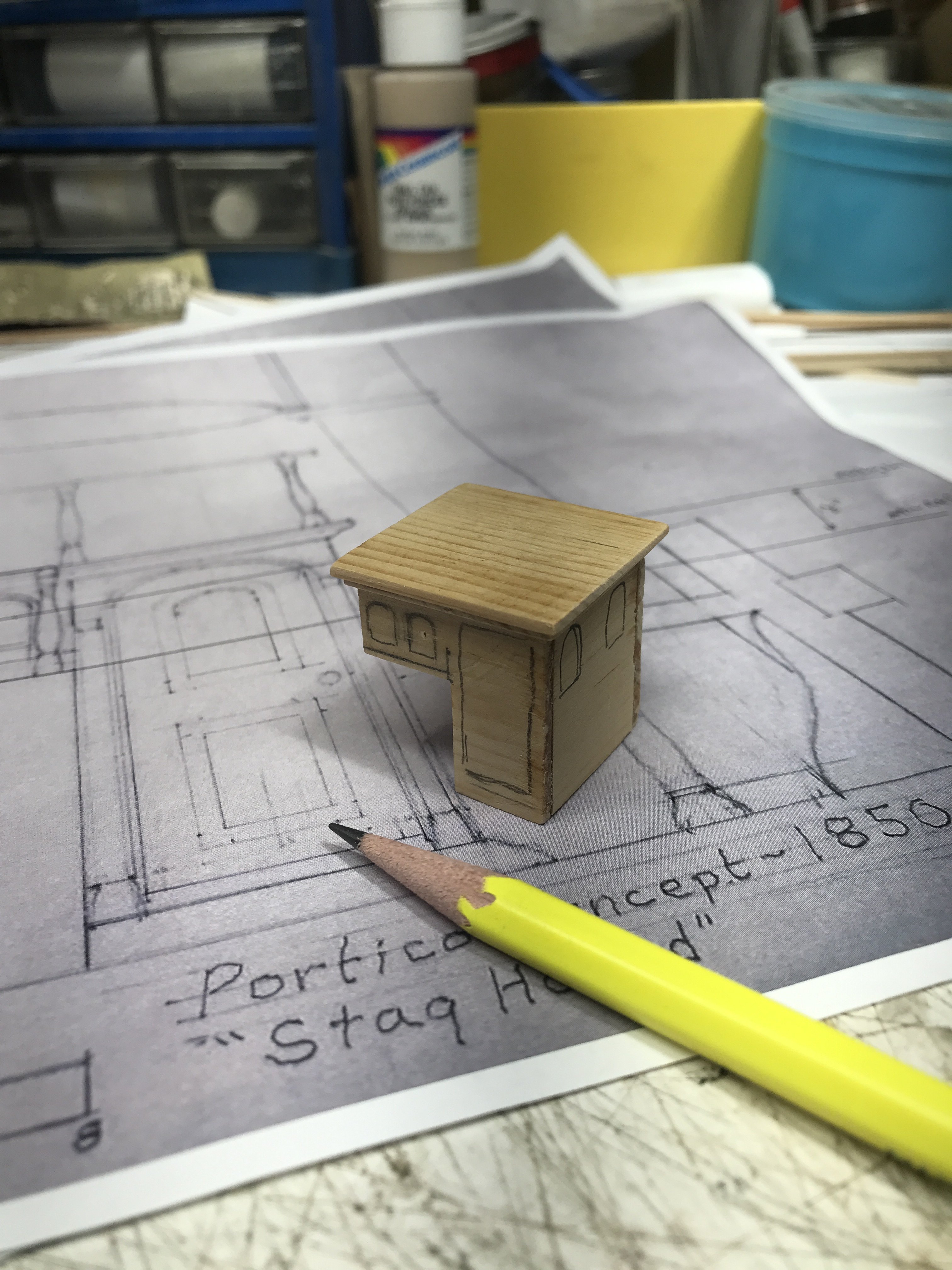
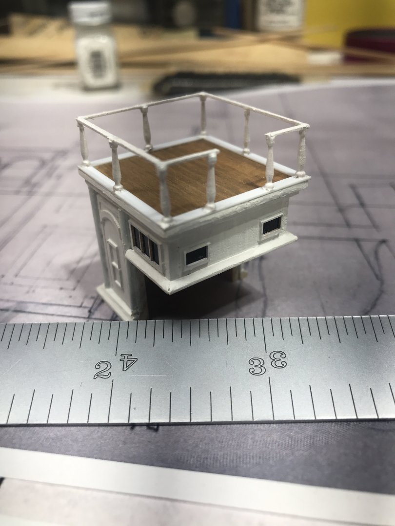
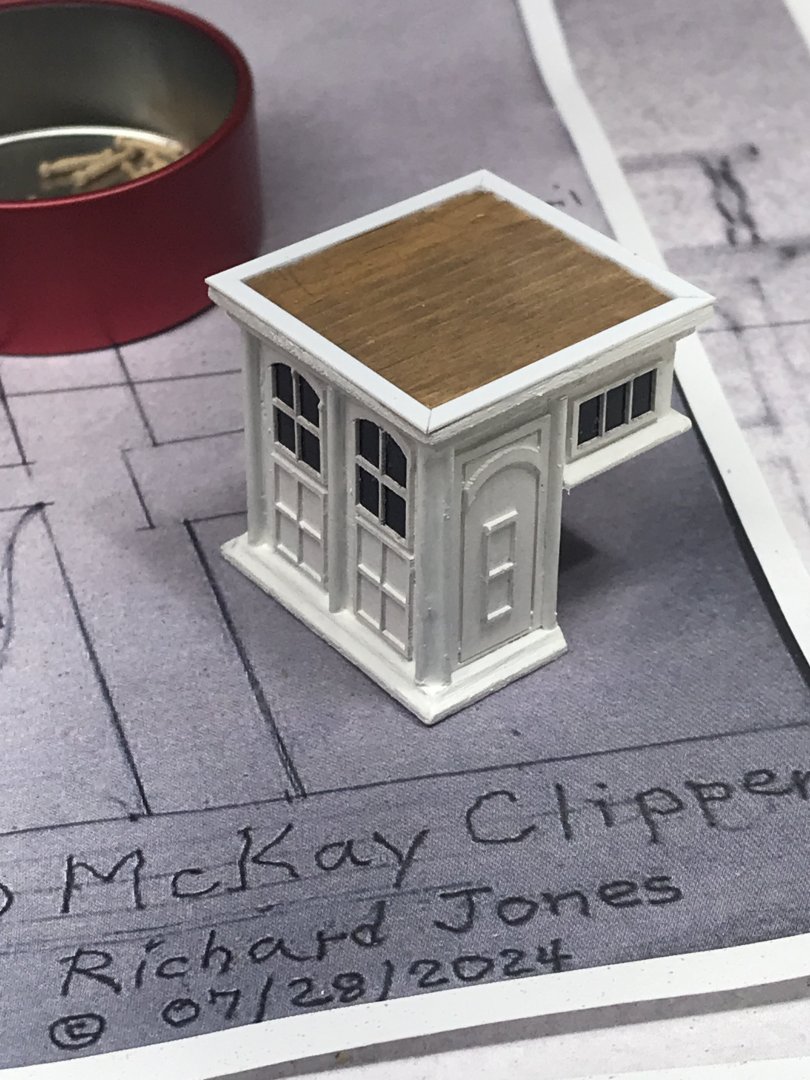
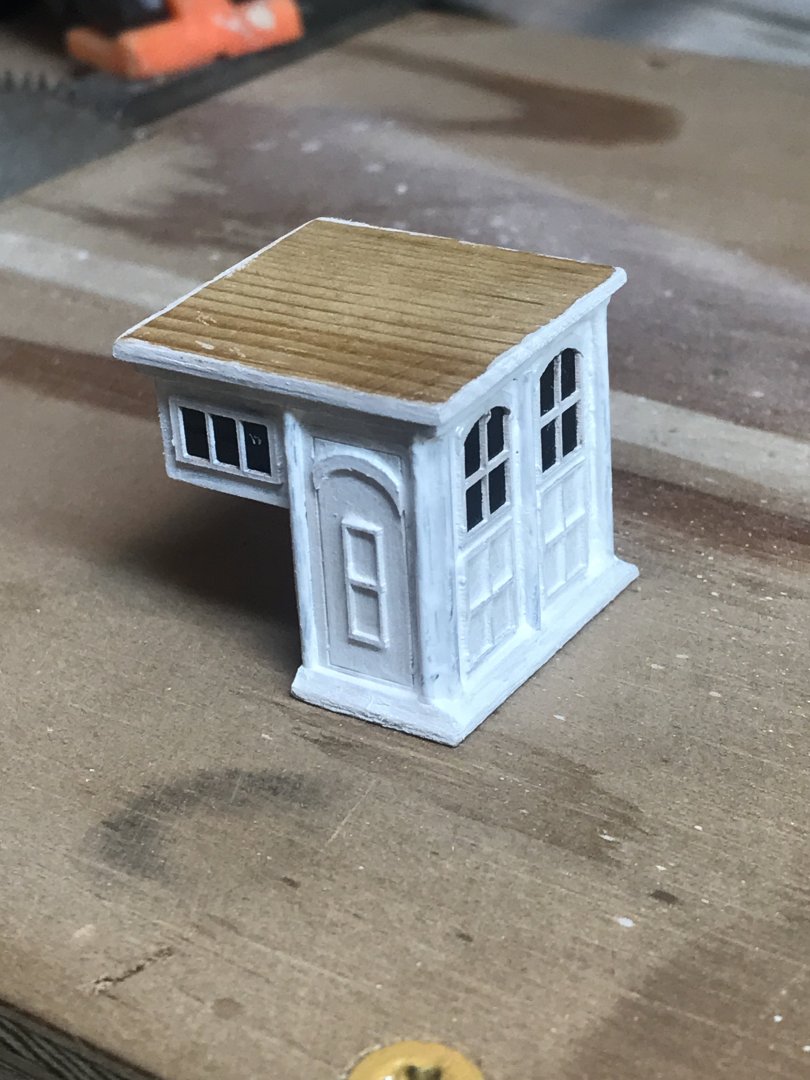
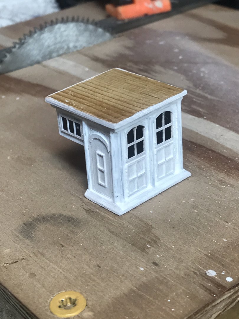
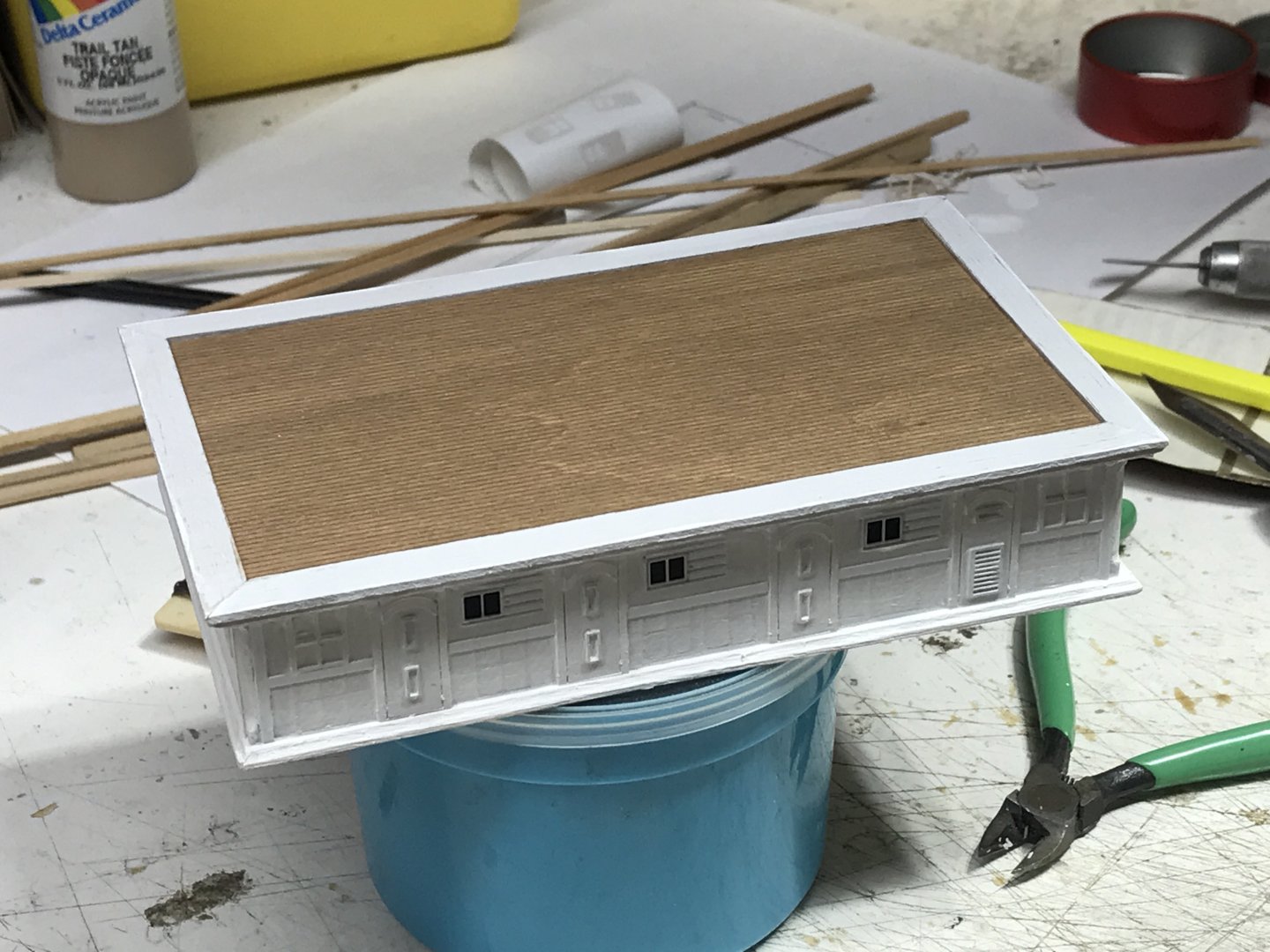
We’ll I finished adding the pillars and windows Put on the first coat of paint too. Rob

-
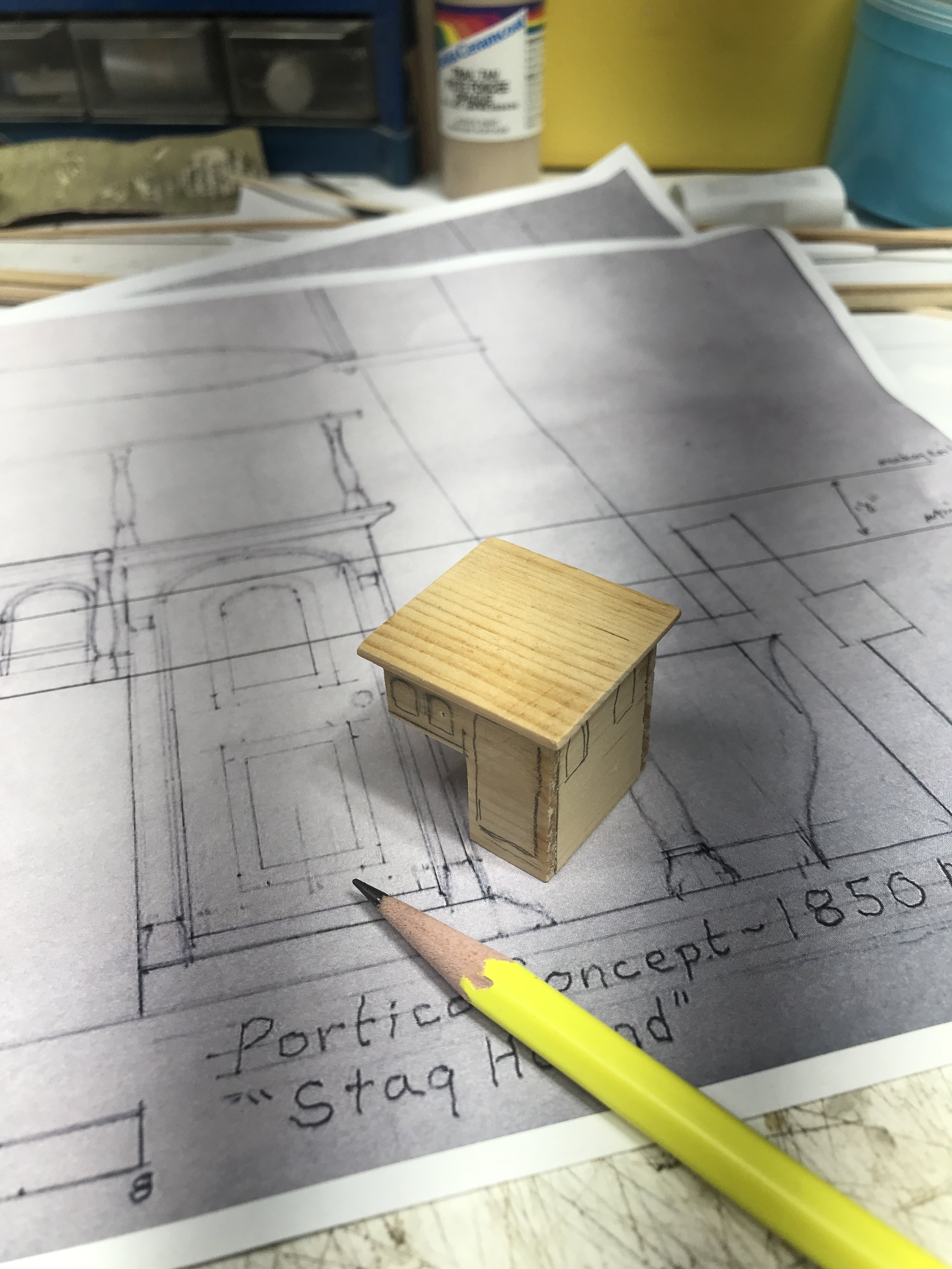
Yeah...when you consider that the entire portico is only an inch square...loading it up with all the details...such as pillars windows and such it gets tiny tight. the space from the door trim to the edge of the house is just about a 1/16". Leaving little room to snug a 1mm+ pillar. I hope to get more done tonight and possibly a first coat of paint. Rob
-
Tooth picks are Waaay to large. Each pillar is slightly larger then 1mm in diameter. I think I might fill in the slight gap between them and form a corner for the portico that incorporates both corner pillars. Slightly different design for the corners, but still in keeping with the original architecture and maintaining dimensional interest. I hope to address it today and add the square/rectangular rear and side windows. Rob
-
As we were discussing this I realized that the portico is nothing more than an access to the floor below(3ft)....but it is also acting as a skylight...in conjunction with its larger companion, just aft. The skylight will have square windows...so square windows on the sides and aft end of the portico will blend in nicely in this scale. The front windows will remain as you have drawn them and as they are presented on Glory of the Seas....depicted in Mike's drawing. Rob
-
I've decided to keep two windows on the front...because I want them to mimic the aft windows... Meaning the 2 in front make way for the mizzen, as the 2 aft make way for the steps. Balance. Since Glory of the Seas was McKay's final clipper..... We can't assume he had finalized his Decore for his houses when he built his first clipper, Staghound. My effort will be to copy the forward windows as you have depicted them...by way of example from Glory's and Mikes rendition. That seams fitting as the portico main face. However, due to the extremely small size I am dealing with...I might settle on square windows for the rest. The curved top is harder to make then you would imagine. I'm experimenting...but have not been satisfied thus far. We'll see. but I think I may be settling on square. Kinda like a skylight. Rob
-
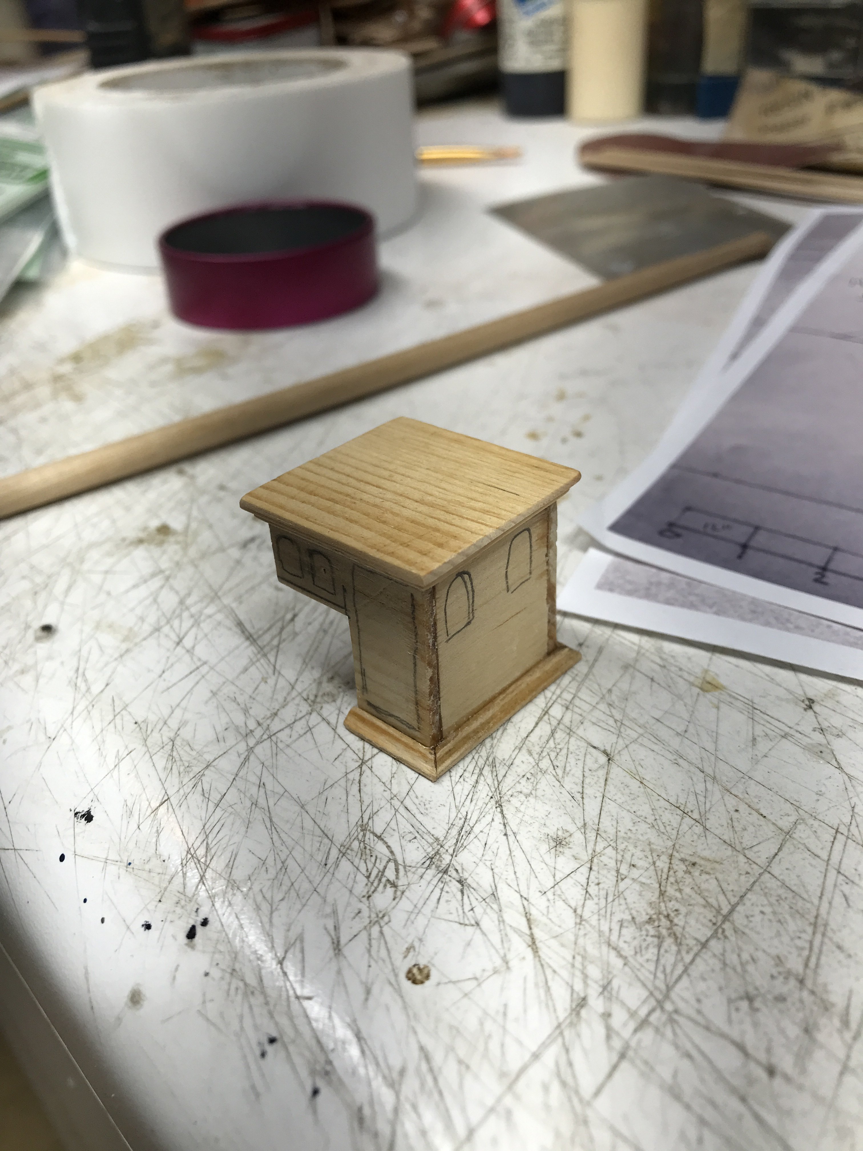
Adding some base trim. Rob
-
I agree…..you’re drawing is spectacular, I will use it as a reference. However, what do you think if I eliminate the center window behind the mizzen mast. They are so tight and very small? Rob
-
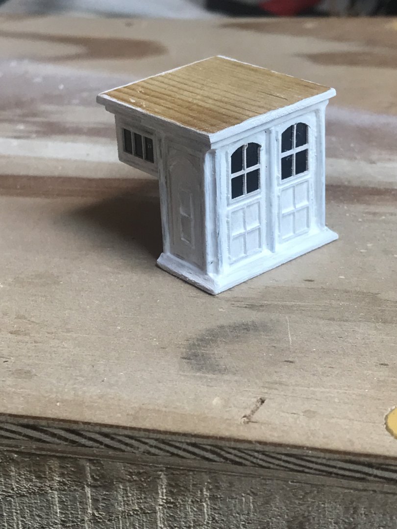
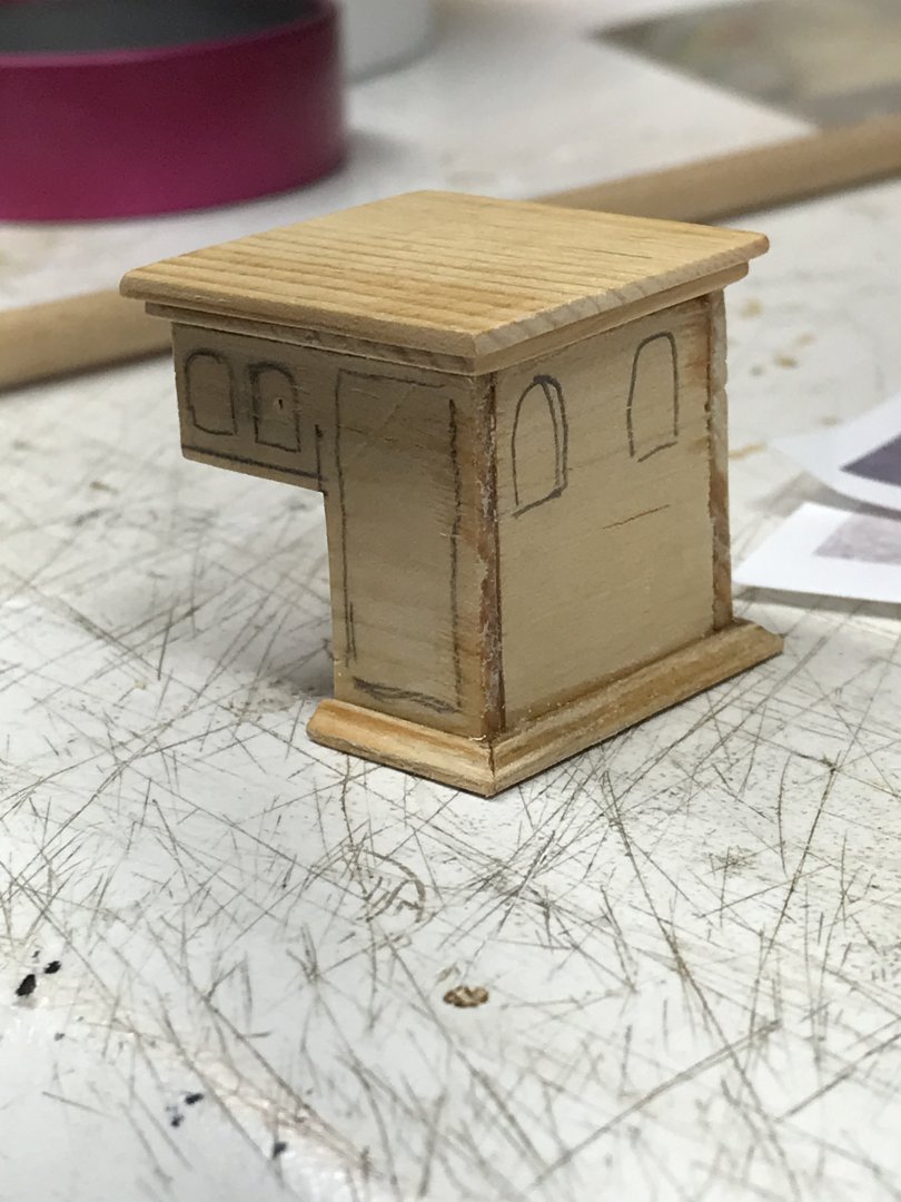
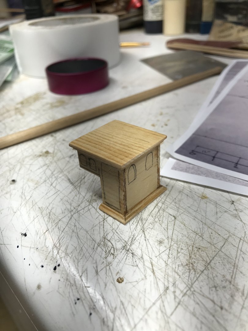
Started the base work for the small portico. This is quite a small structure, basically just a doorway passageway. Ron


-
You're doing a great job Rich. Did you get my message about SOS? Rob
-
Wonderful job and very nice display....she has a great home. Again...super job. Rob
- 235 replies
-
- 6
-

-

-
- Banshee II
- Bottle
- (and 1 more)
-
Beautifully drawn. I love the embellishments. Only one question.....what made you decide on a 2ft overhang? Is that to mimic the roof overhang on the main cabin? Which is what I was going to do....but I was thinking more like 1ft. Review Glory's overhang on her main cabin. It's not even an overhang...but more like a gradual step of descending trim. Great job by the way. Rob
-
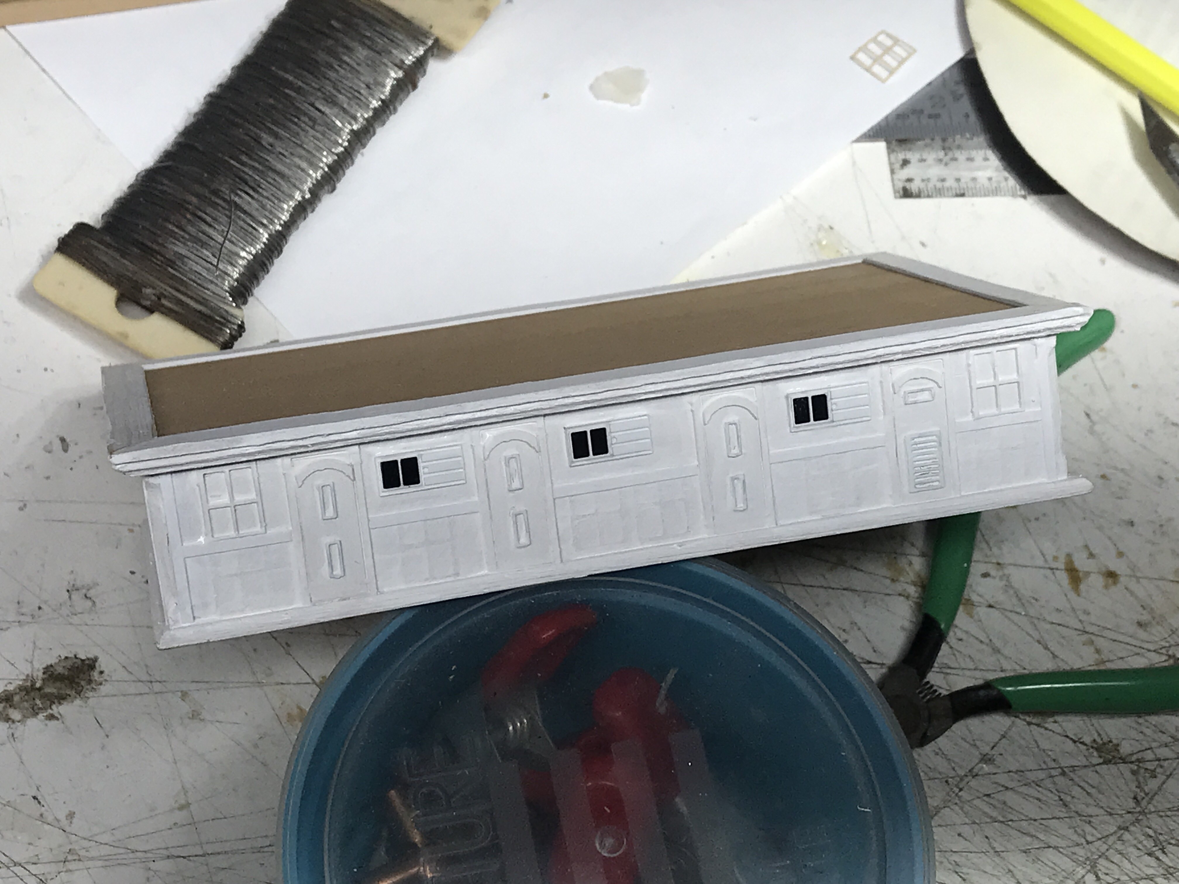
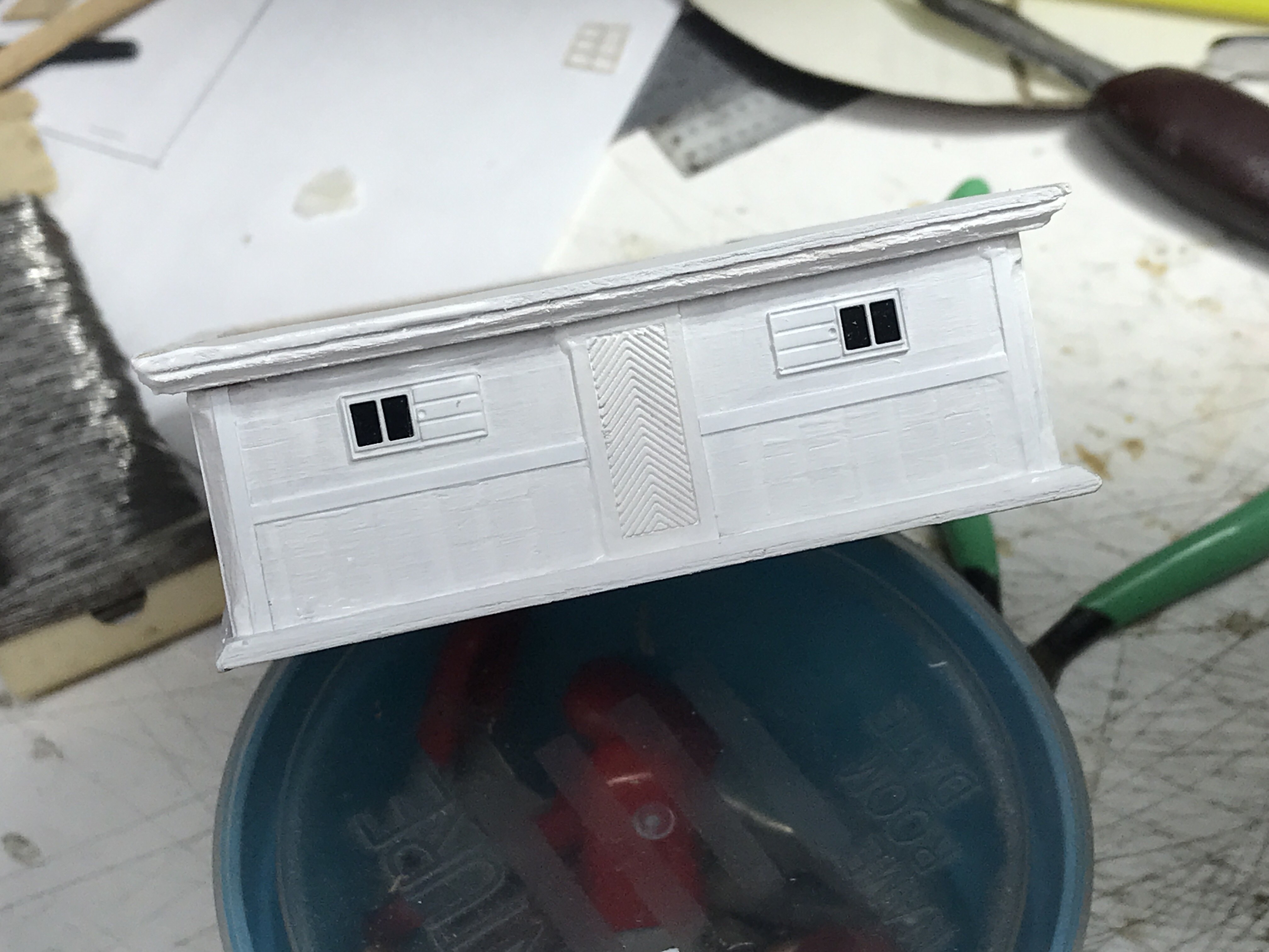
Did some work on the main house. first coat over the removed trim. Some sanding to clean up some roughness due to paint infiltration. Rob


-
Yeah…..this is one of those particulars that requires *group think*….to fully realize. On one hand we can take what is said as gospel,,,,,,and on another hand we can freely dispel what is said. All balancing on a thin blade. I’ll remove the lower paneling in keeping with McLeans account.
-
I wasn’t offended. I look at every aspect. And evaluating Intent based off historical actualities. Somebody may say something, but if it flies in the face of other known facts……I’m questioning it. I’ve changed my mind, in the light of community concurrence and one eyewitness’s vague description. Mind you, it’s Duncan McLean’s description……vague as it is. IMV. Rob