


Schrader
-
Posts
304 -
Joined
-
Last visited
Content Type
Profiles
Forums
Gallery
Events
Posts posted by Schrader
-
-
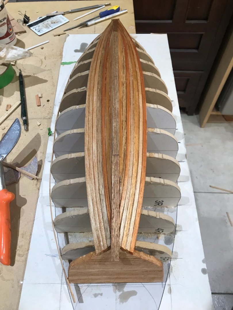
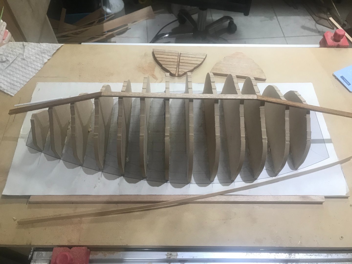
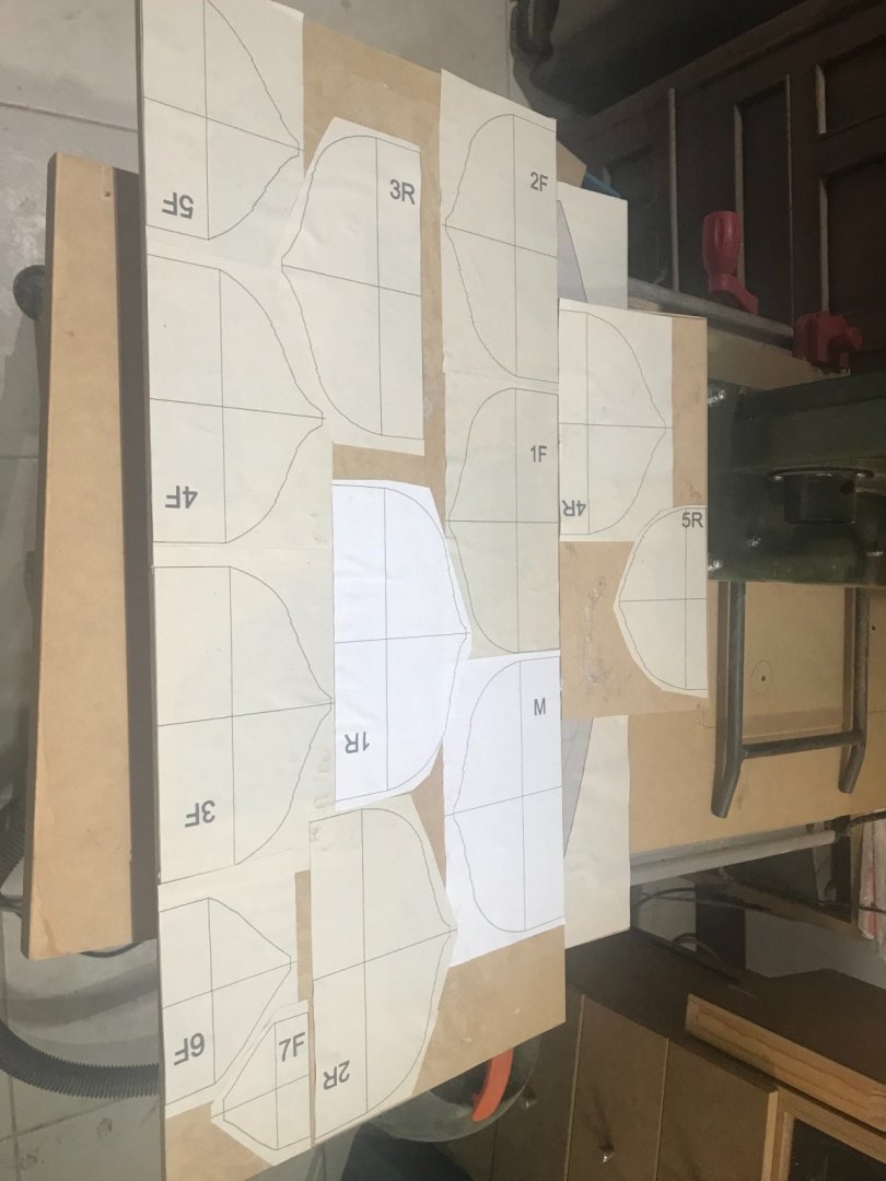
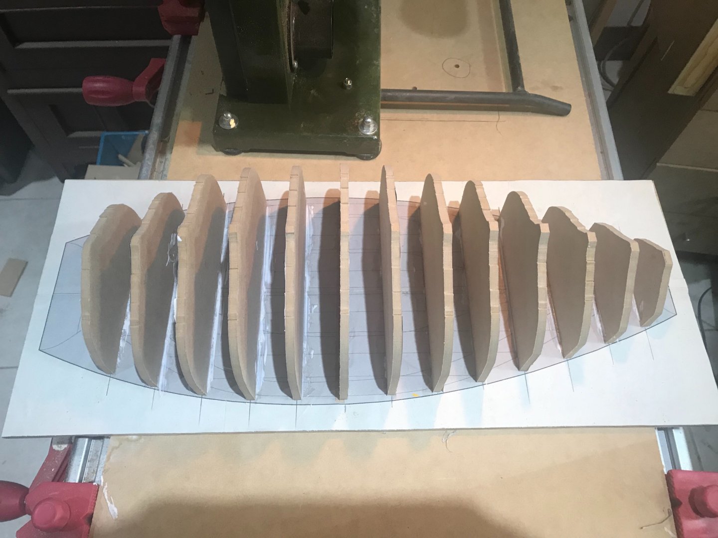
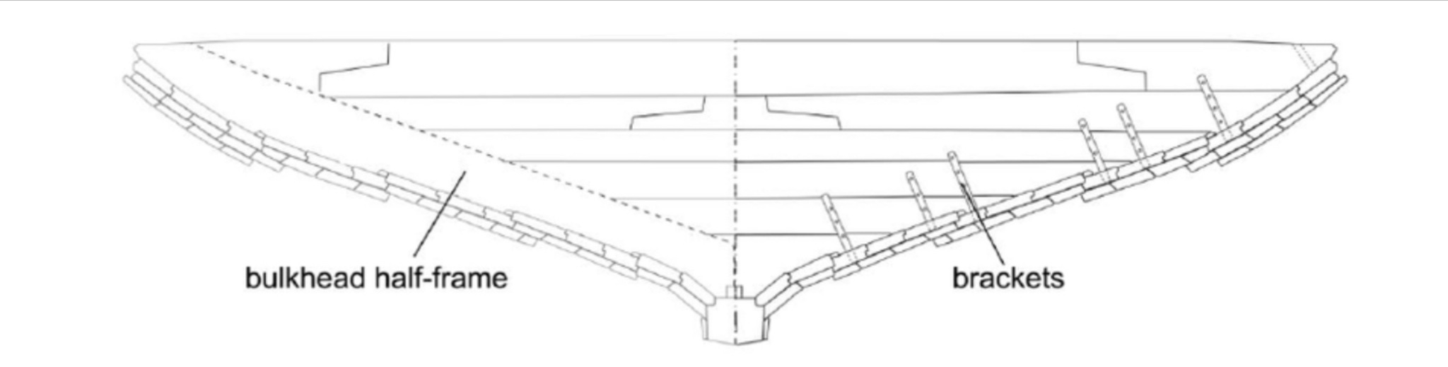
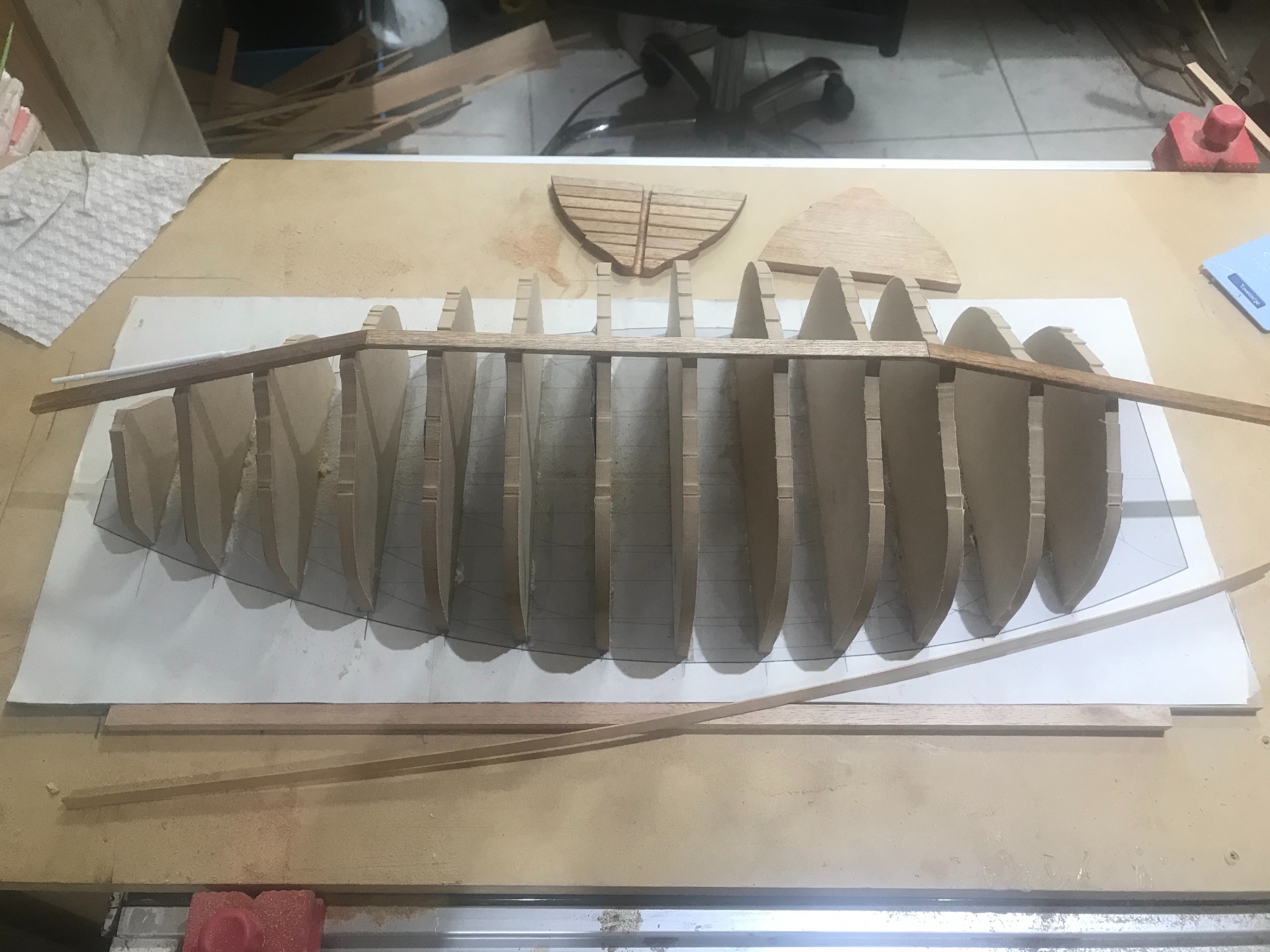
I just decided to change the wood to a lighter one. CEDAR..... that was the wood used by the Chinese....... here with the half frames
Now it is time to start to deal with the brackets.
- Tony Hunt, GrandpaPhil, mtaylor and 1 other
-
 4
4
-
-
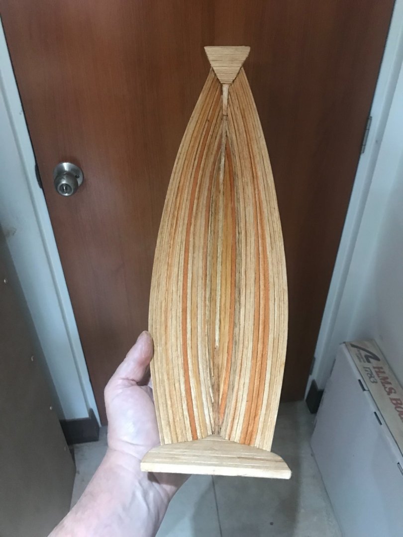
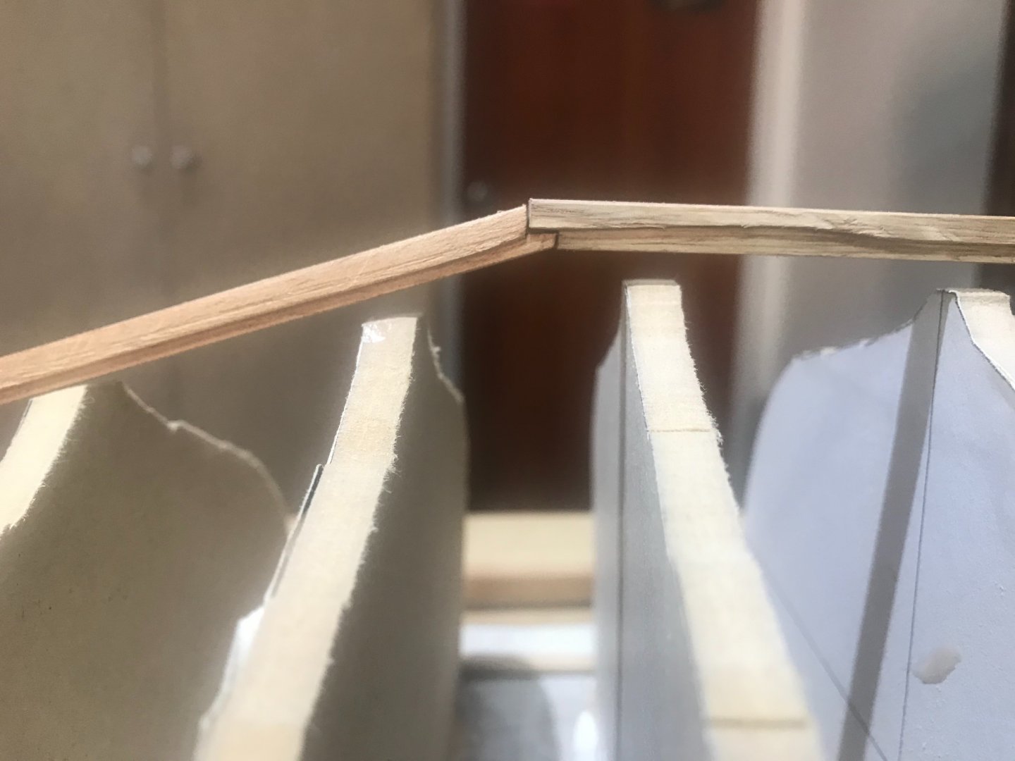
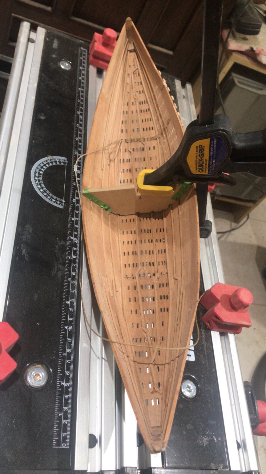
Here we go again. Plank # 14 in place
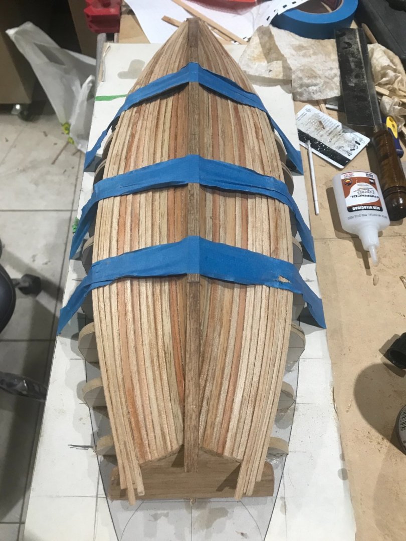
I’m going to take the hull out of the mold.......🤭

looks OK!!!!! The planks definitely were trying to come back.... but I think it is good enough to sand it and moving on....


It is time to try one plank-bulkhead......

here we go!!! It looks good for me..... Next step..... 11 more bulkheads with their frames and brackets
- Cathead, GrandpaPhil, Tony Hunt and 5 others
-
8
-
-
On 2/8/2021 at 7:05 PM, Louie da fly said:
That planking is looking very good. I take it the bulkheads get discarded after you've got the planking done? Something that happened with me when I built a model on a plug was that the elasticity of the planks pulled the hull sides inward after I'd taken the plug out and before I could put the frames in. I had to put in some temporary structure to push the sides back out to their correct position.
In your case you can probably avoid this problem if you replace each bulkhead with a frame, one at a time, rather than taking all the bulkheads out and then putting in the frames.
Steven
Steven
in the Chinese ships the bulheads are part of the structure. They with the half frames come like a team to give the strength to the hull and create some compartments that are use to separate the different kind of cargo and also to protect and keep the water in one place in case of.

- GrandpaPhil, Cathead, rkwz and 1 other
-
4
-
On 1/25/2021 at 7:14 PM, woodrat said:
Having made the shell, the question was: what type of framing? As this putative varmint was known to predate (and postdate) the cog and to derive from the low countries, it was thought safe to position it close to the nordic tradition. So, I have decided to base the framing and decks on the known wrecks the Suldelev 1 and 3. The Skuldelev 1 was a deep sea trader or knarr (knørr?) and was quite wide. It was a sea-going vessel and a reconstruction sailed around the world. It also was deep enough to transport horses (as seen in the Bayeux tapestry.
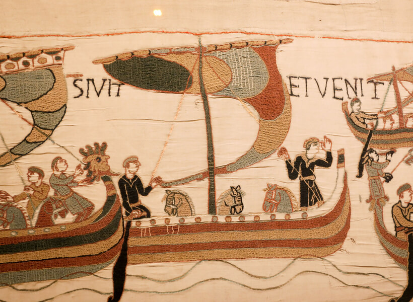
This was judged to be a suitable model for the frumious varmint.
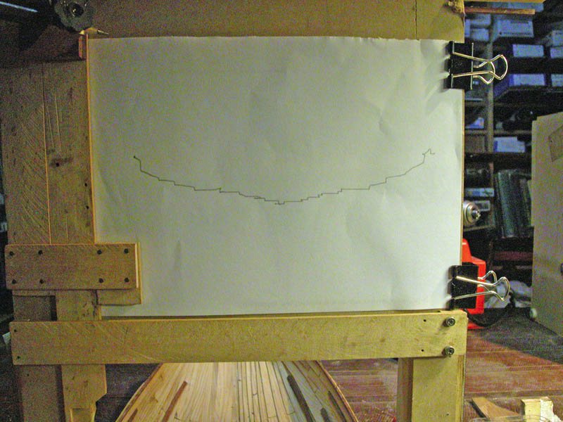
So, how to make the floors. I presume these were made by eye and shaped to fit the clinker flooring. In order to do this I adapted and modified an analog plotter which I made to take lines of a half hull for my carrack.
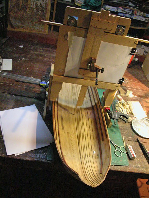
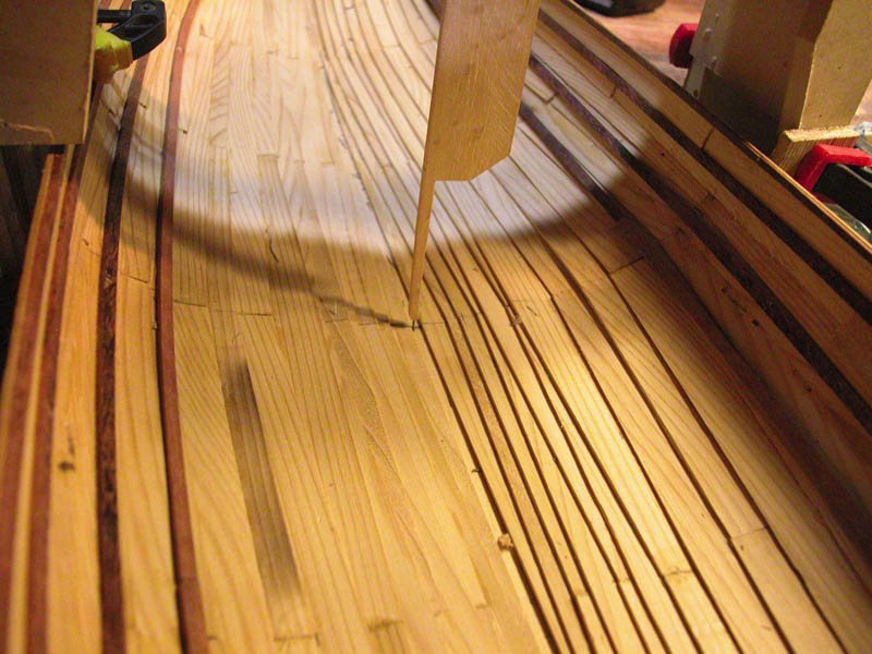
 first attempt.
This barge is going to hold a lot of bread!
Cheers
Dick
Definitely this is a really good Idea!!!! I would never go that far by myself. Well designed and even better executed.
thanks for sharing
-
Thanks Steven.... I am concern “so concern” about the same thing. It did happen to me in the Byblos and, I solved exactly in the way you are describing.....with a provisional “bulkhead


In this particular case I’ve been checking the hull and is working quite well and the rabbeting (even when I was thinking that not) is helping a lot to keep the strakes in its place. I’m thinking to stop the planking in the strake No 14 install the bulkheads-frames and then finish it. Right now I don’t see any other option
Thanks Steven for always been there
-
-
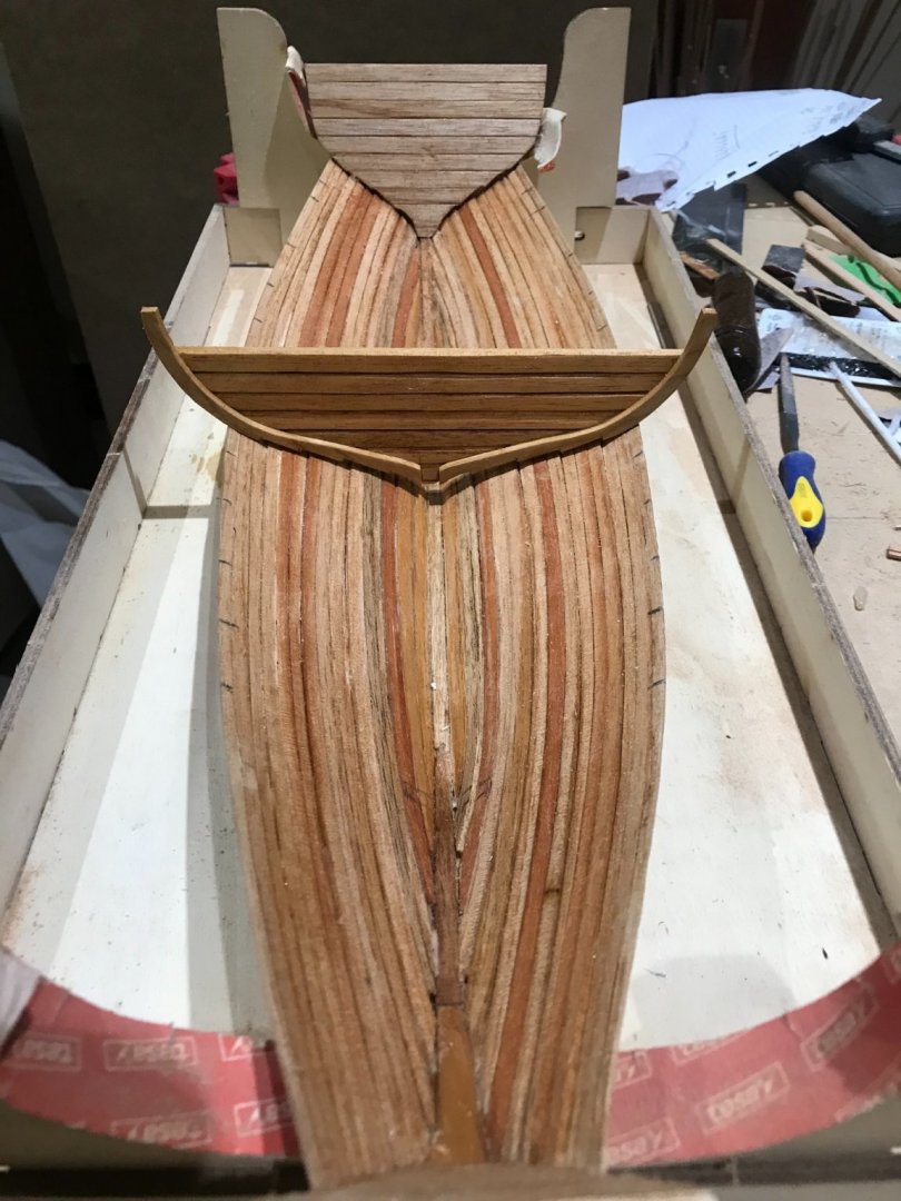
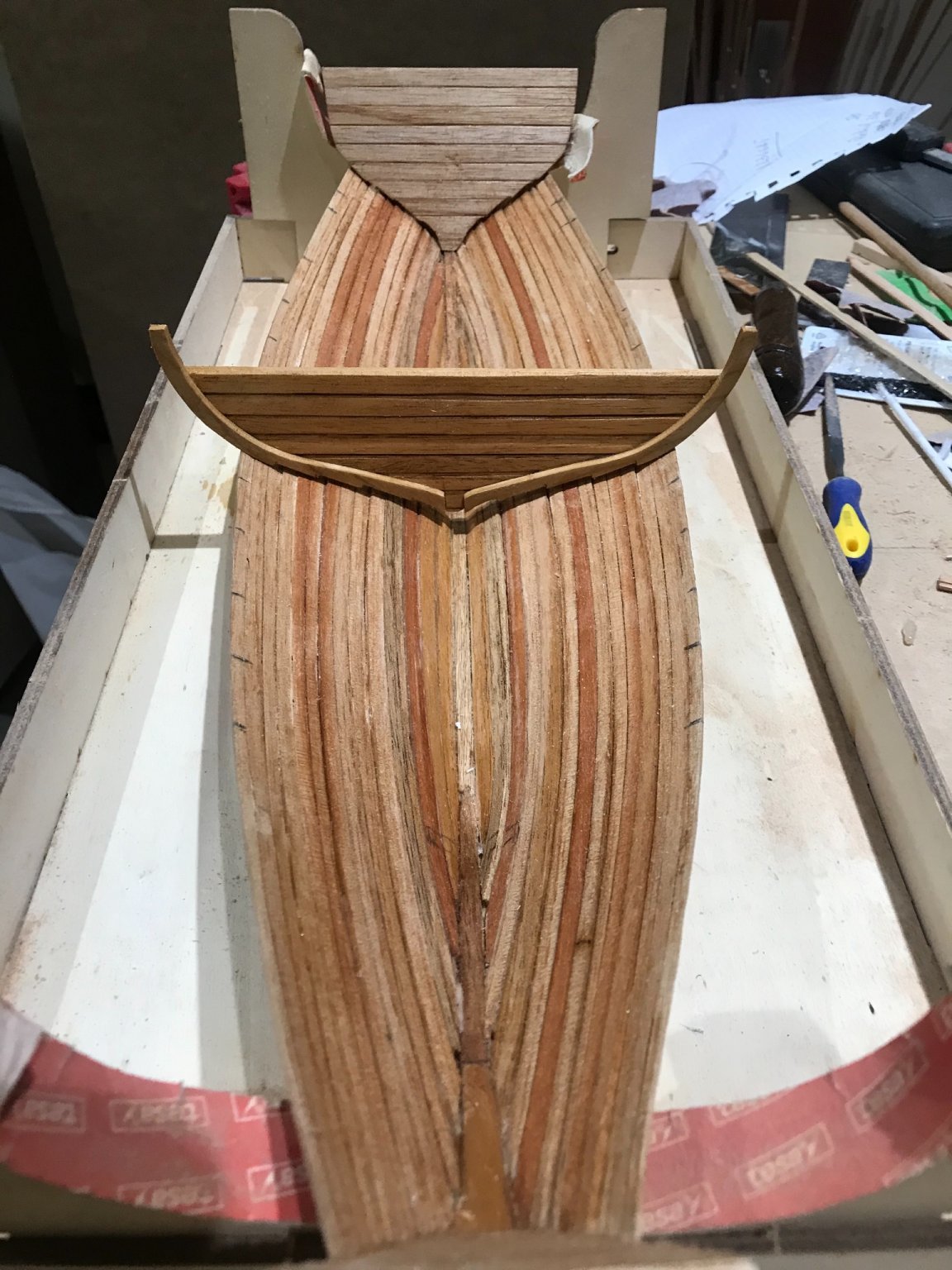
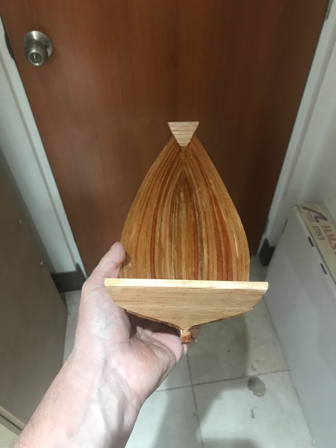
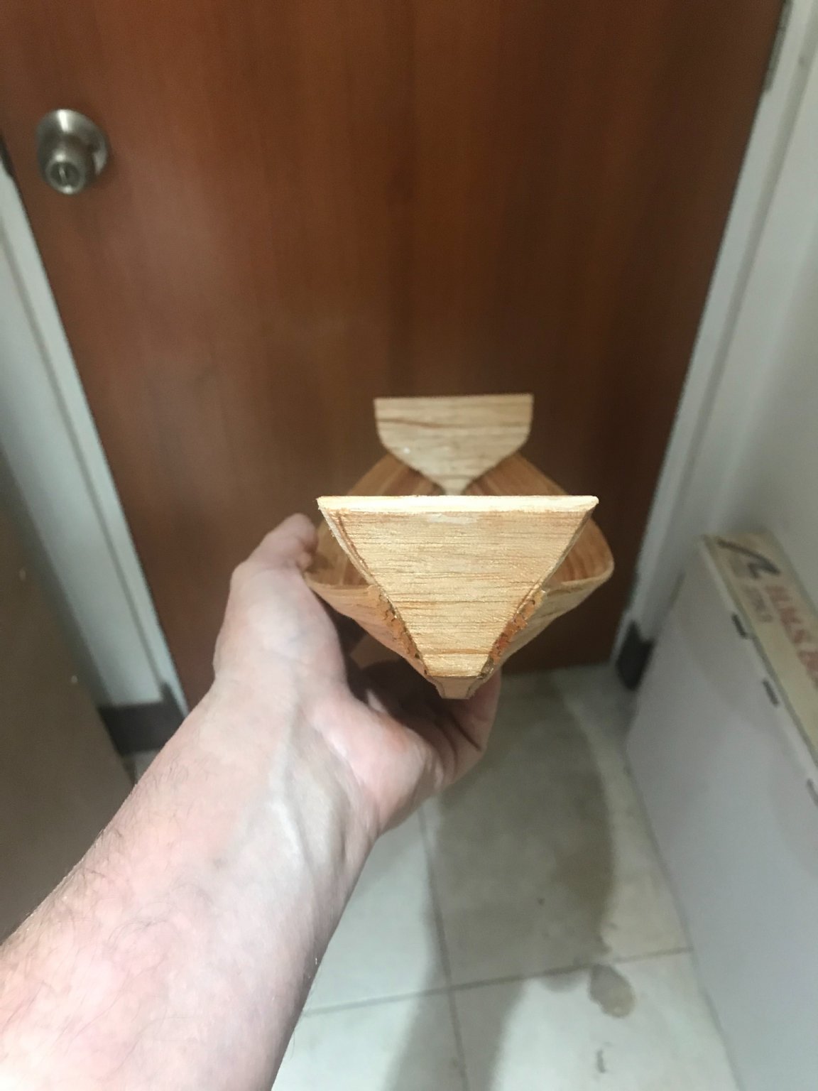
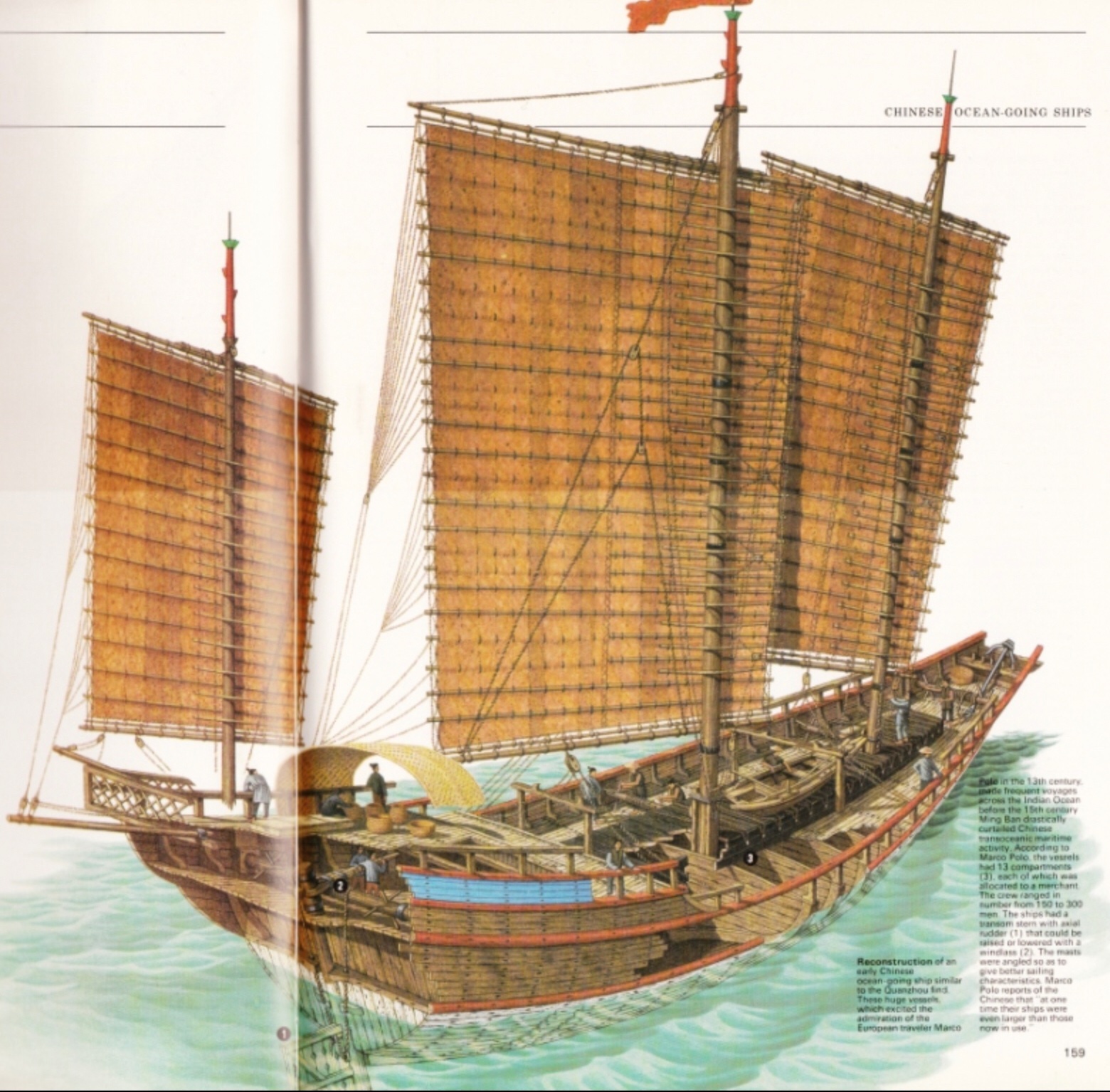
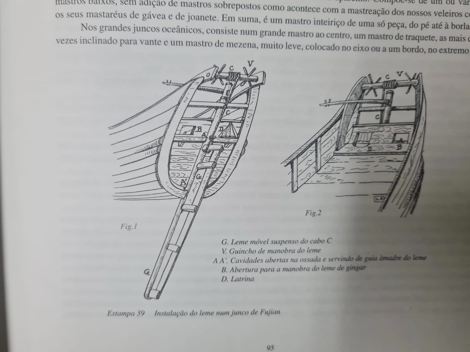
As you probably notice, these ships had transom either in bow as in stern. The stern one we already described, was used not just to increase capacity, also to received the back piece that was used as a “mechanism” to operate the rudder..... The internal layer, received also the first planks layer and the second (rudder mechanism) received the second planks layer.....
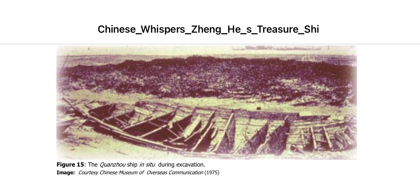
Well.... here some pictures in the “real life”....
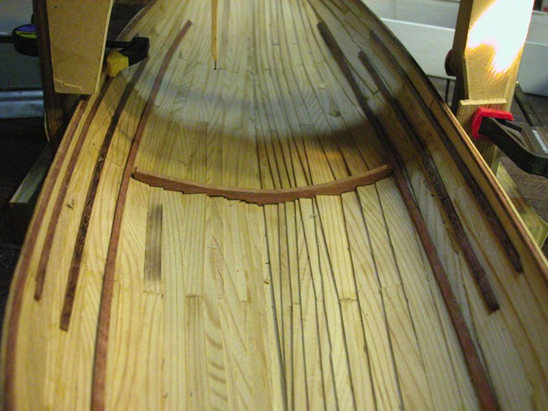
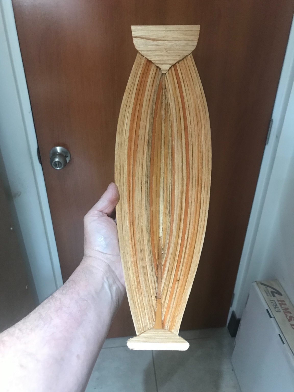
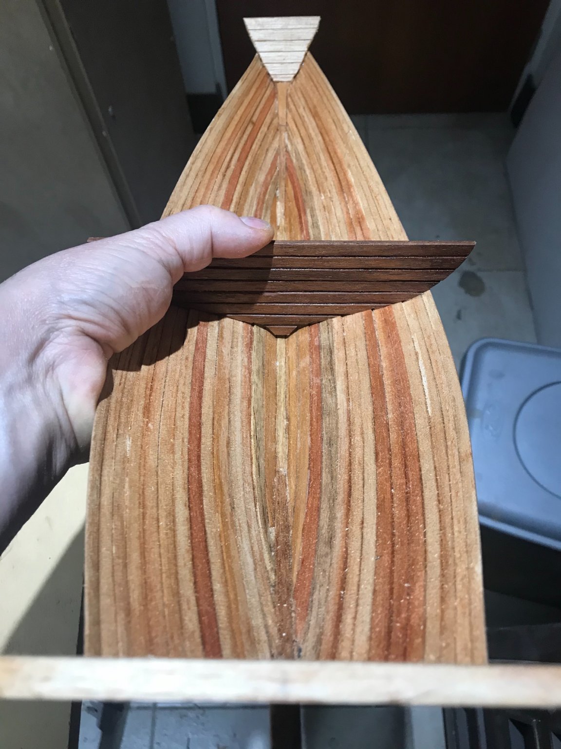
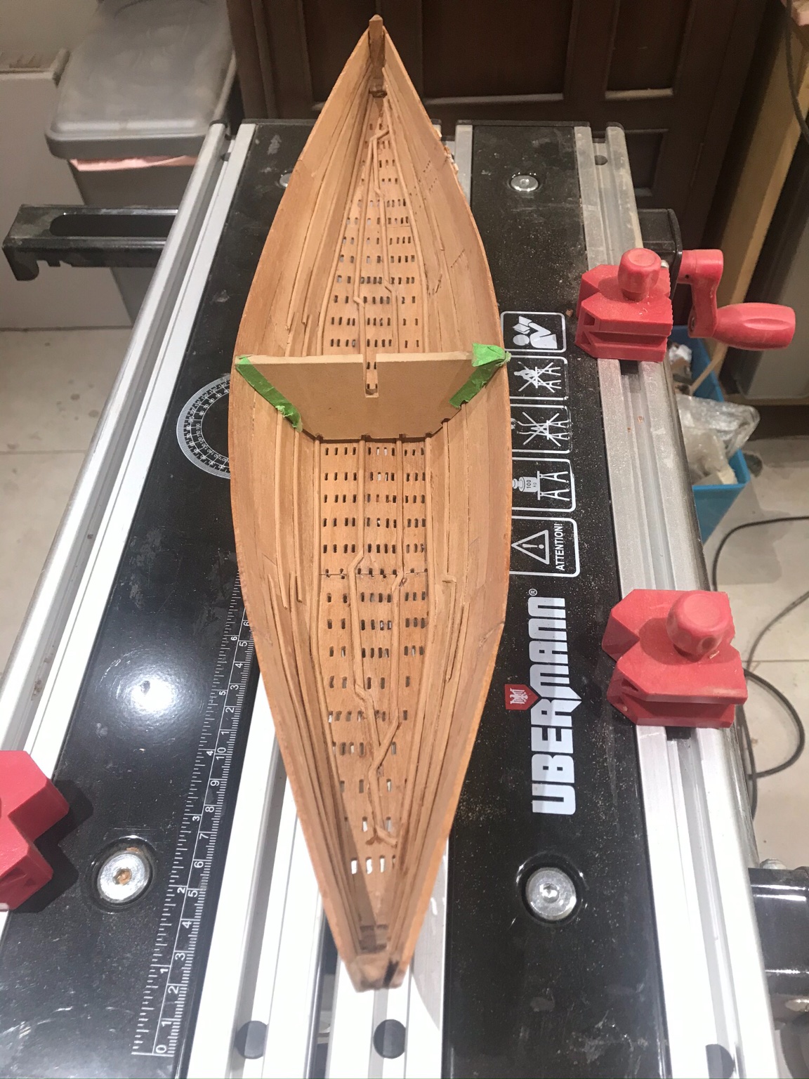
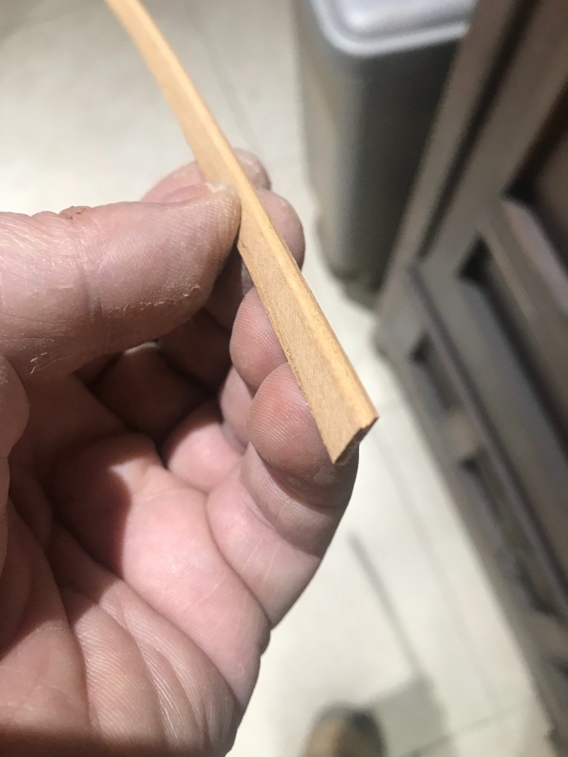
YESSS !!!! I have started the planking with all its difficulties.....
FIRST..... let’s remember that it need to build PLANKING FIRST FRAMES AFTER. This is pretty much the same that Vikings and Egyptians. Also let’s remember it has 2-3 planking layers
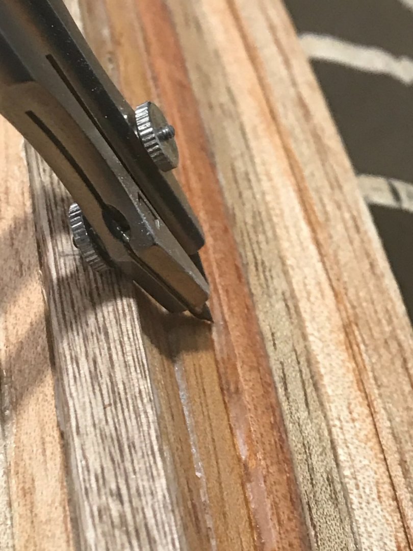
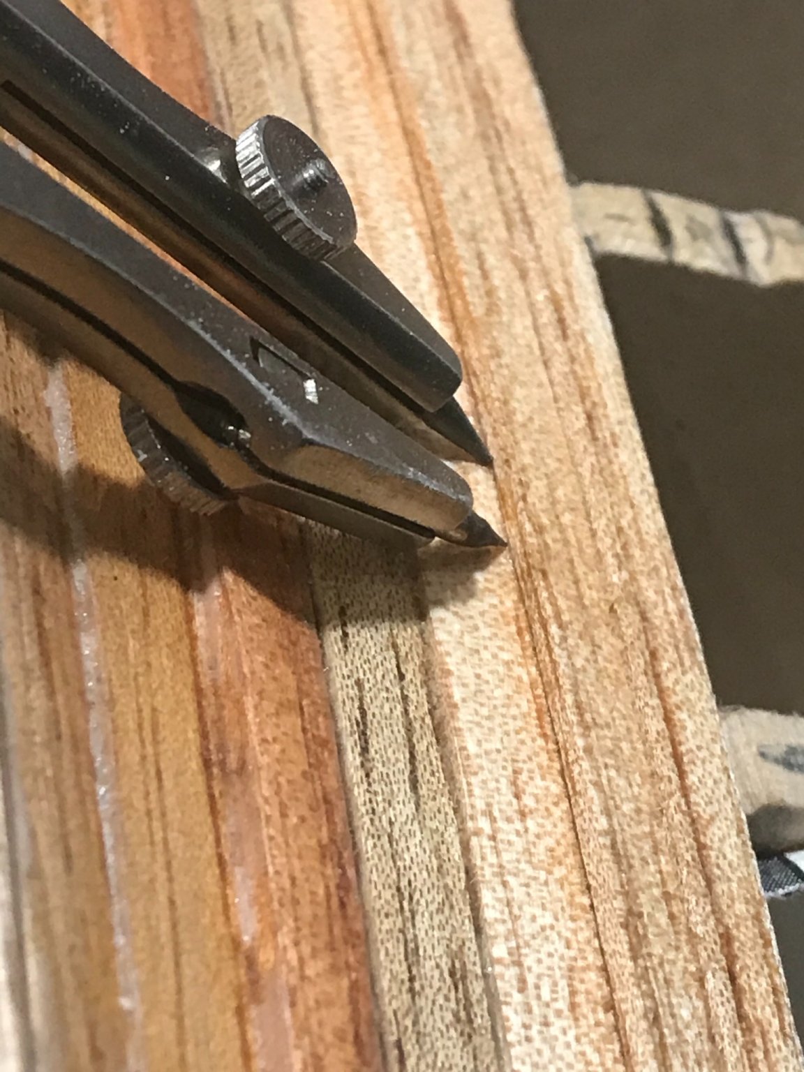
It is a “kind” of clinker with e very specific distribution. The first layer, is rabbeted as you can see. And let me tell you.... I did it.

It really helps a lot to fix the planks.
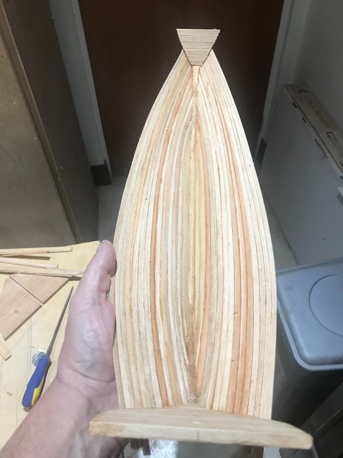
Here some how I’ll try to show how the clinker looks like.....
We will continue with the planking up to the bulkheads level.... Then we will install the “team” bulkhead-Frame” to complete afterward the planking. Do not forget this is just the first planking layer.
Before going to the second layer we will need to figure out how to proceed with the brackets....
-
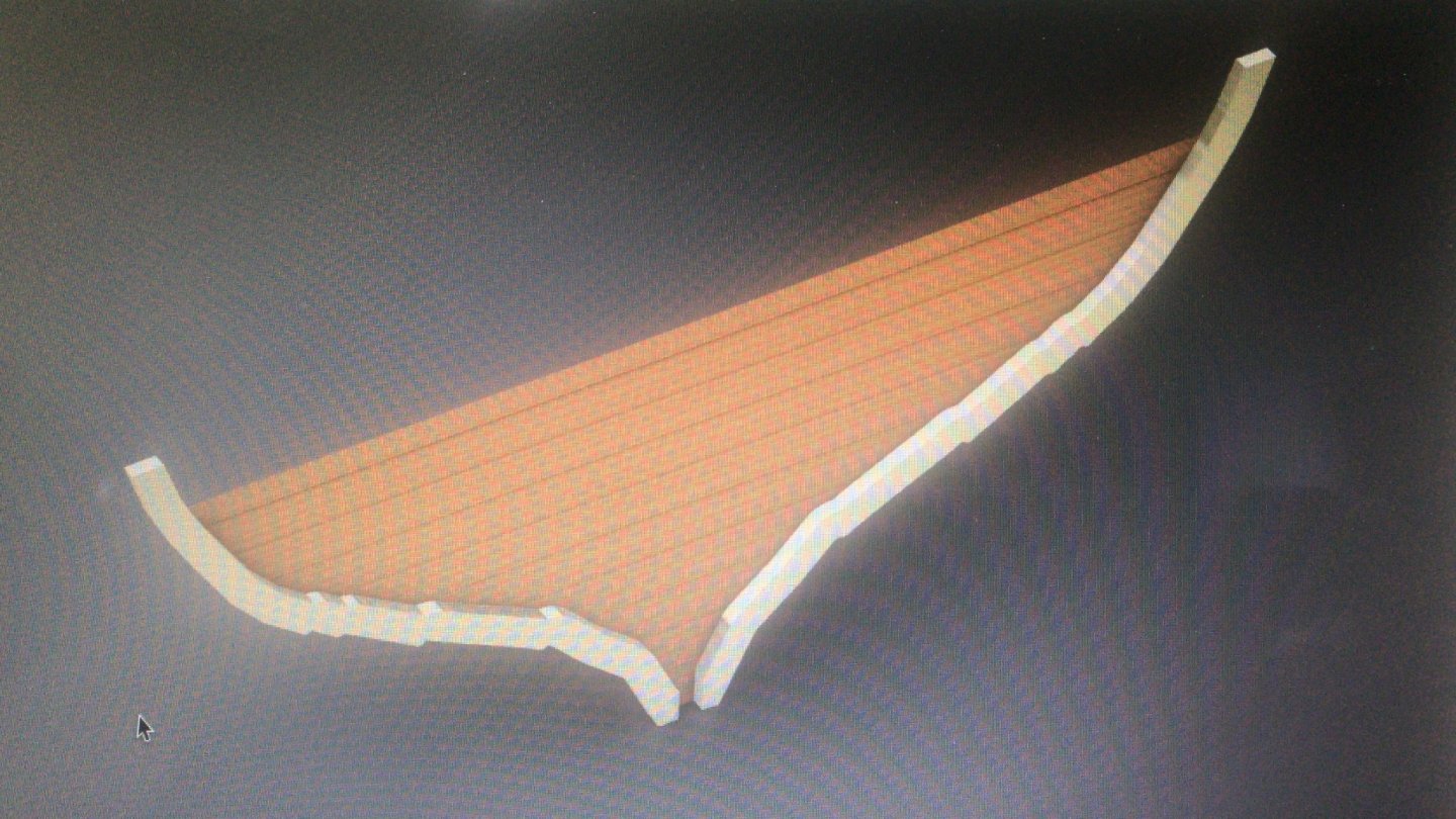
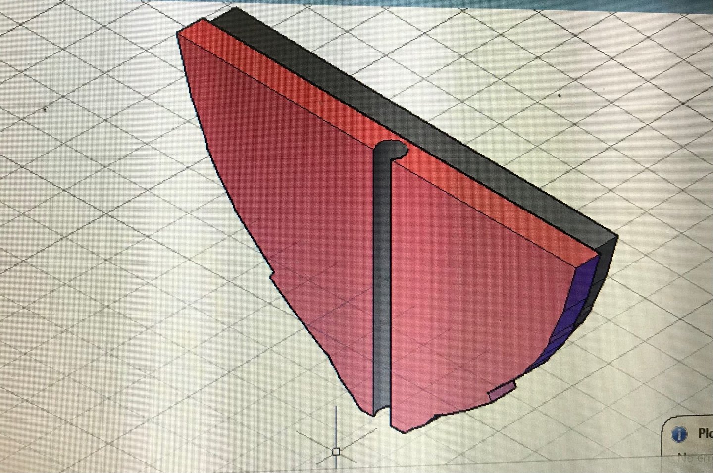
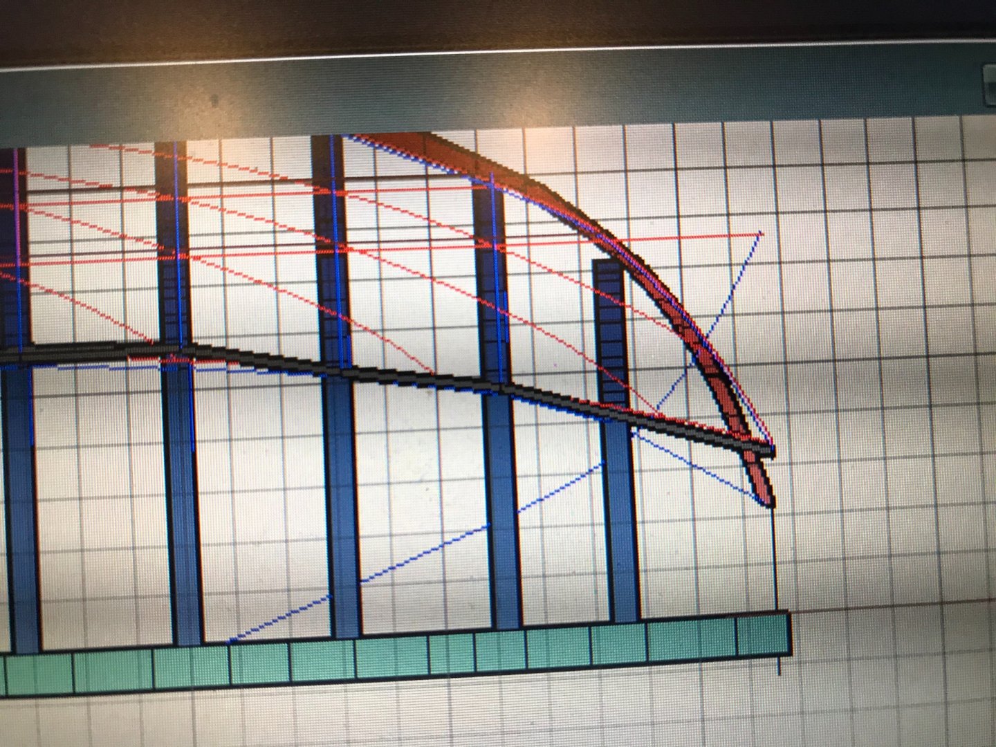
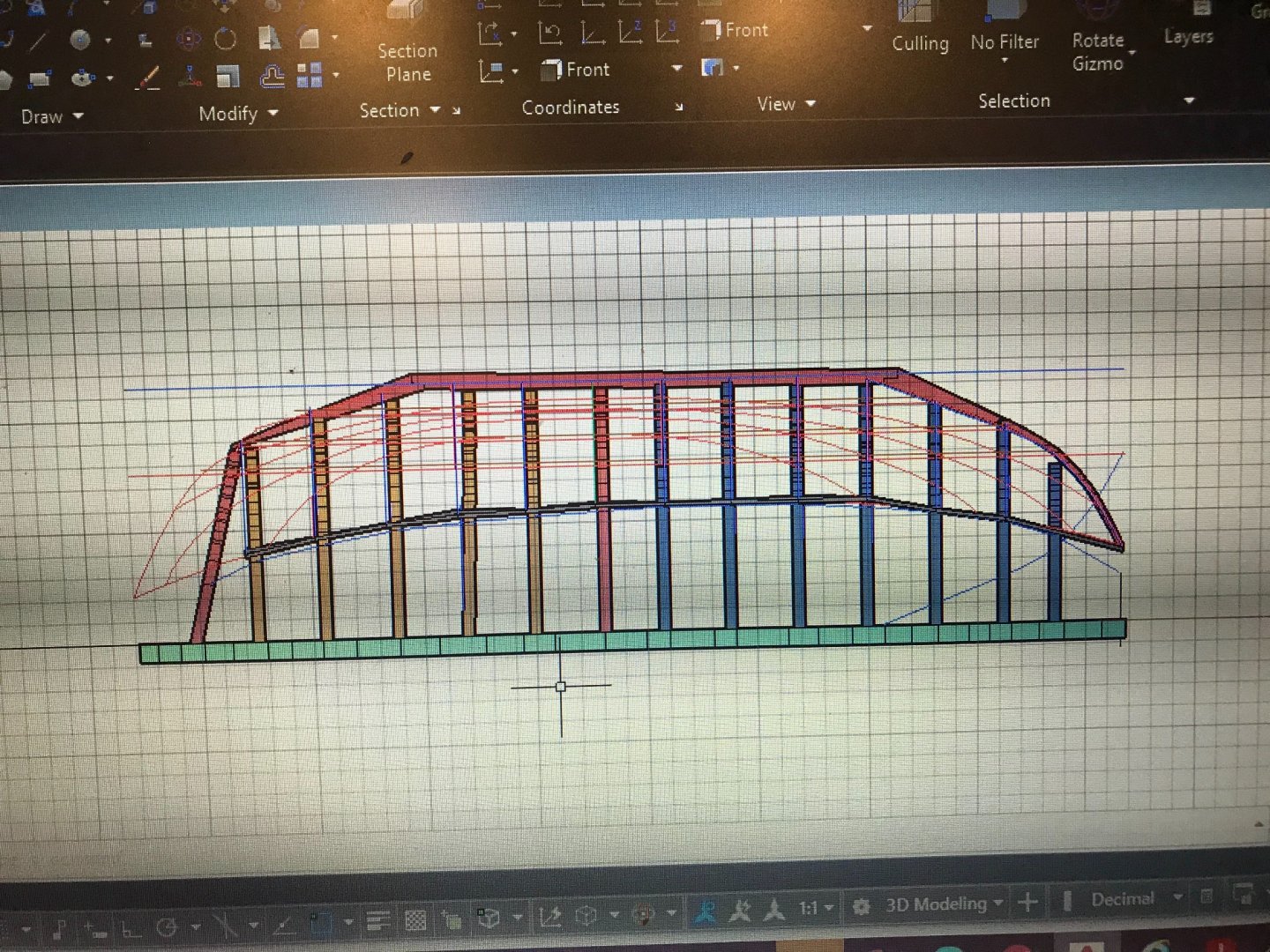
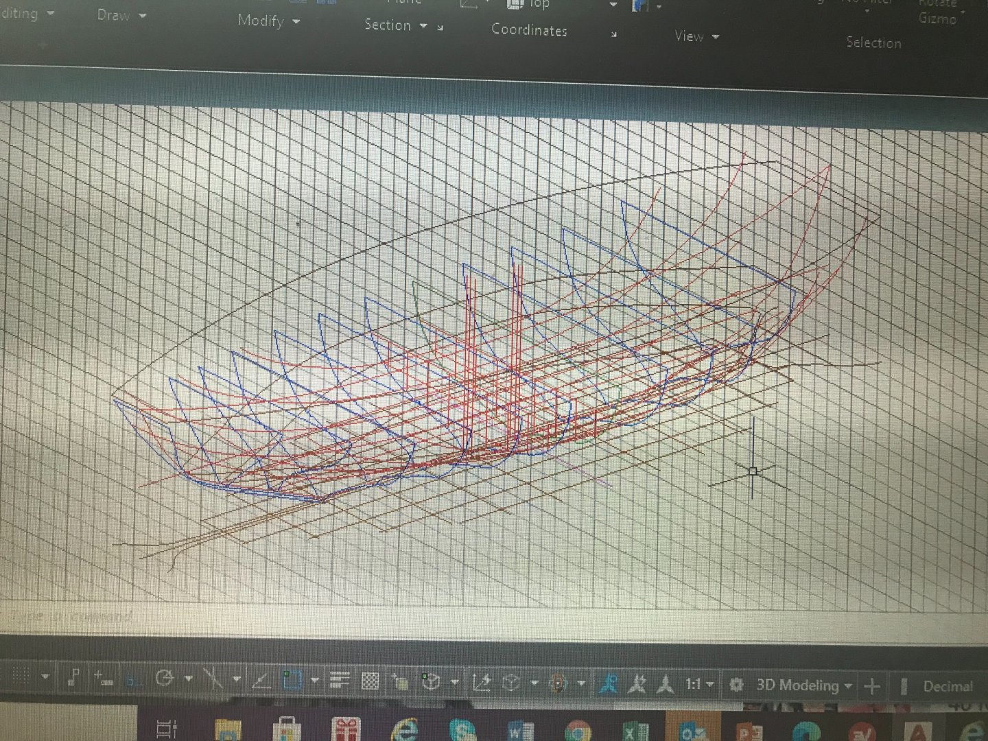
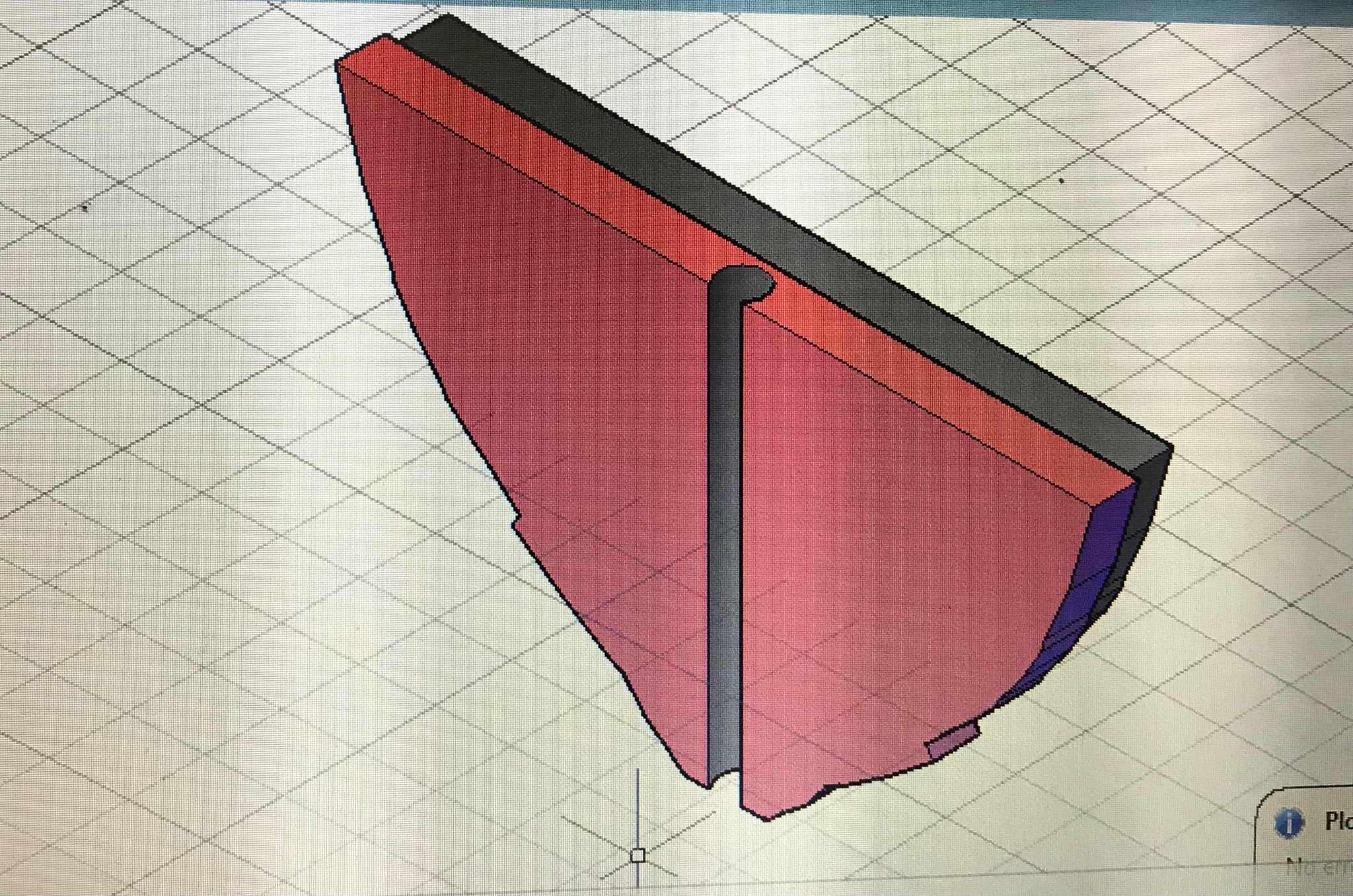
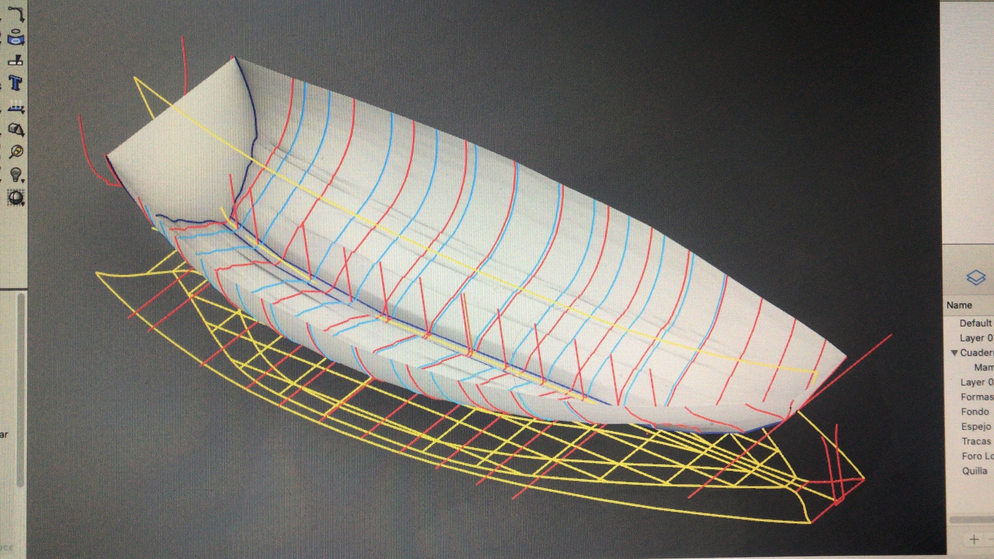
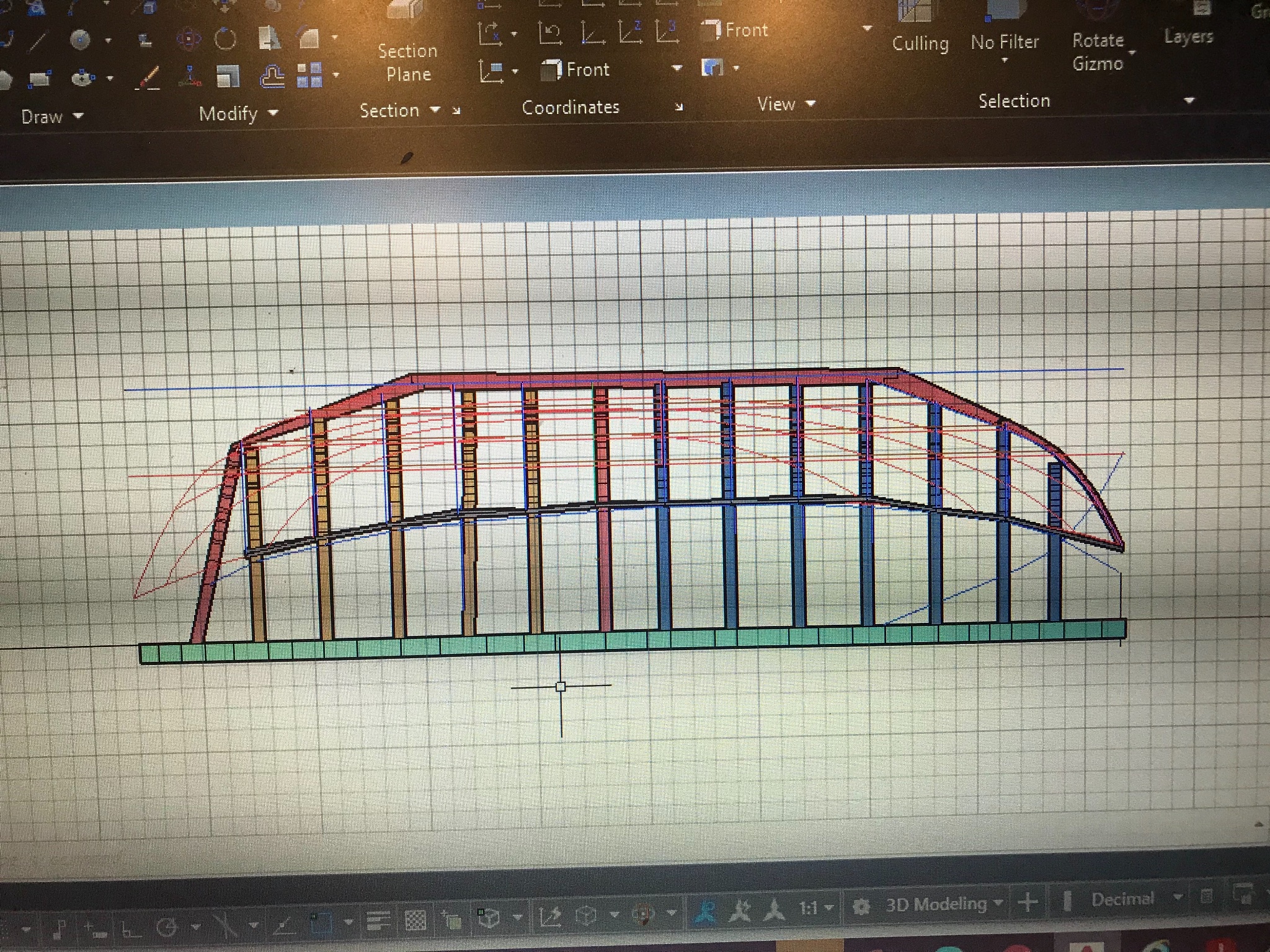
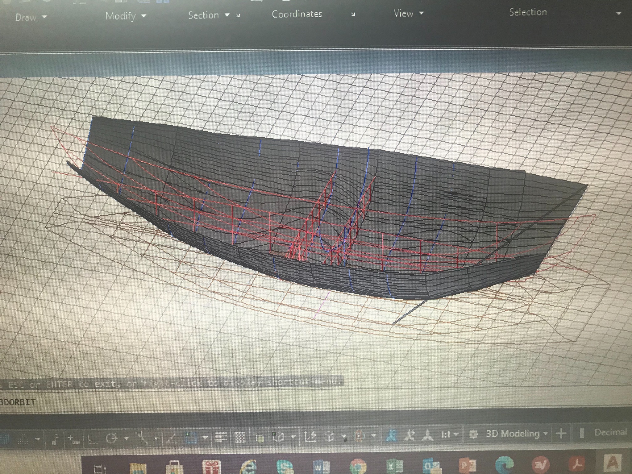
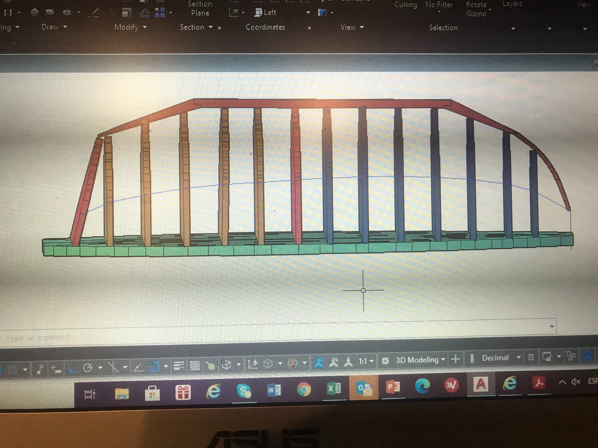
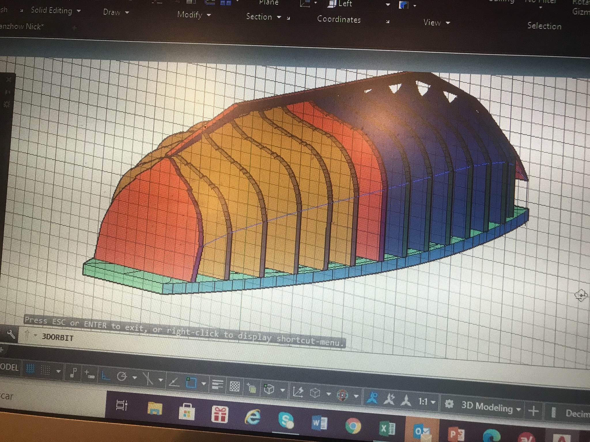
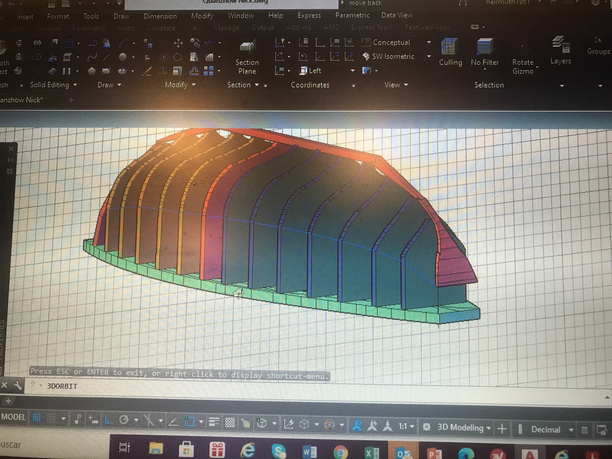
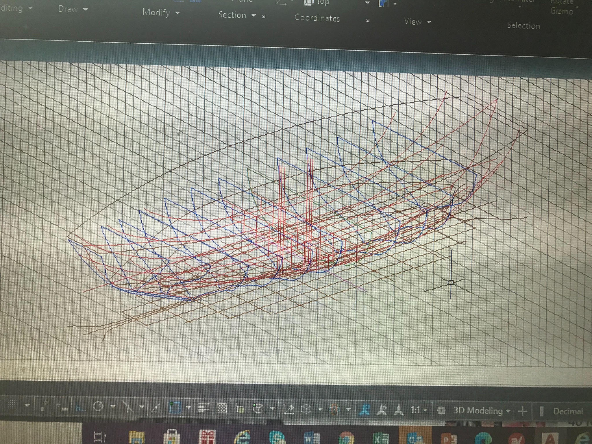
Long time since my last posting...... I’ve been working in my Rhino skills....at the same time understanding new subjects about the way these ships works.
here my new reproduction in Rhino....
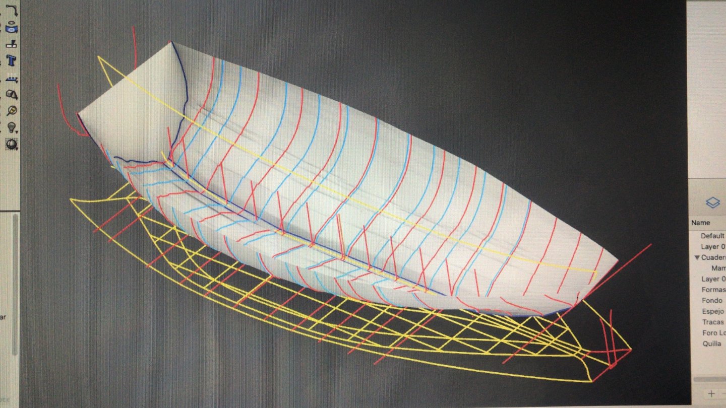
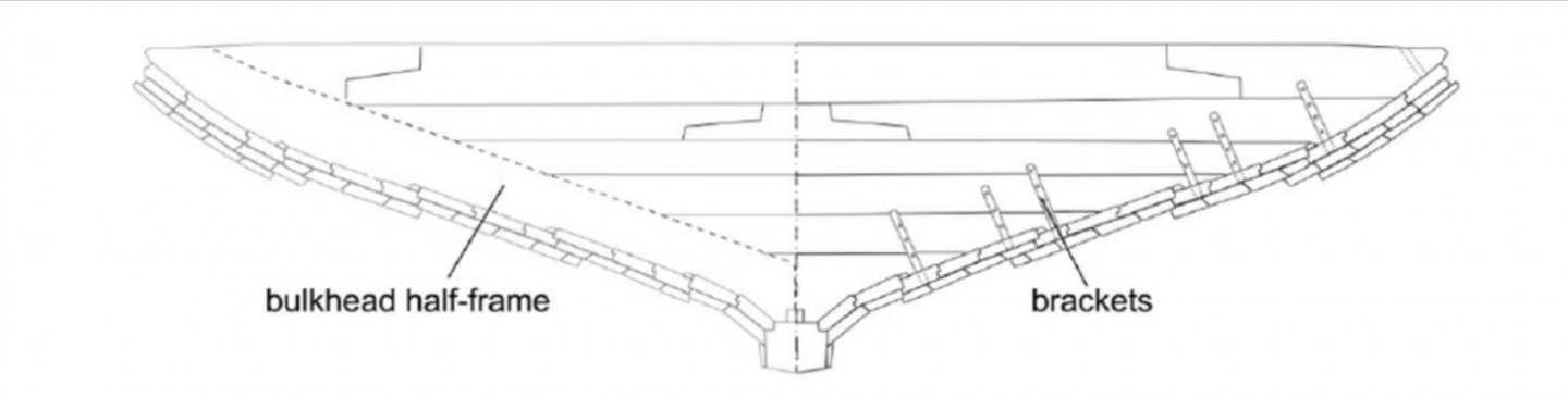
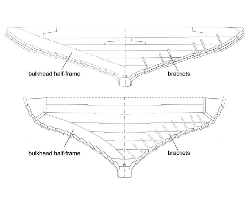
It looks much better. In the frames you can see two different lines. The red ones are the false frames to build the mold... The blue ones are the Bulkheads-frames. And this is how those elements are going to look like....

The frames that in reality are half frames, work as a connectors between bulkheads and planks. Because the bulkheads “planks” grain direction, the connection with the hull wouldn’t be that effective so the needed the half frames to serve as a connectors.
The real hull resistance is in these three elements
PLANKS - FRAMES - BULHEADS
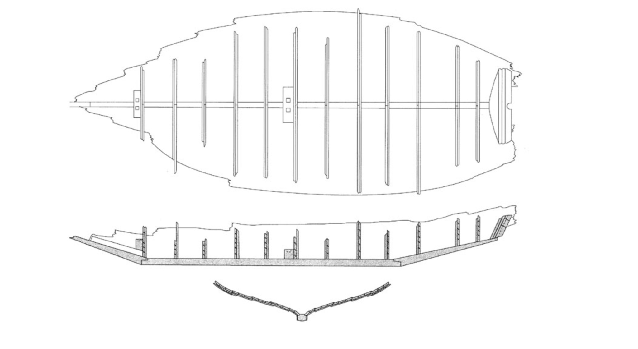
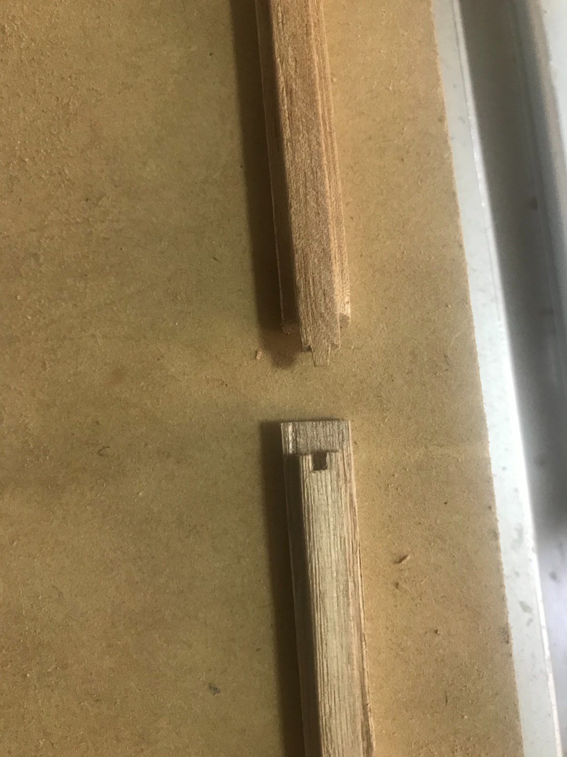
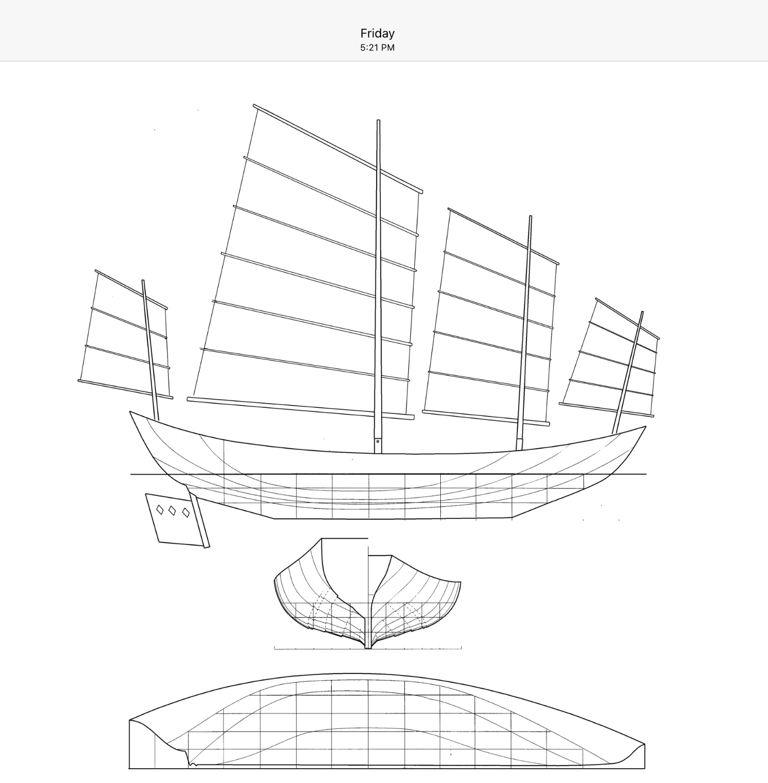
THE KEEL.....
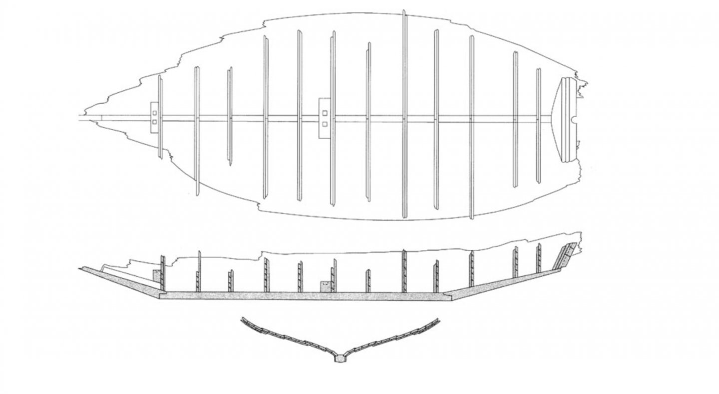
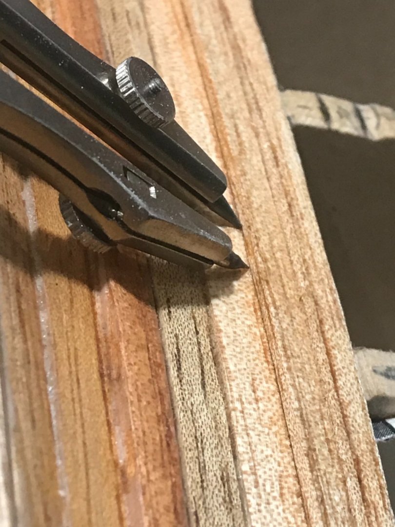
It has three elements.... the middle one the is originally made of camphor wood and has 12.57 m long (aprox). The forward part is 4.5 m long made in pine and slopes upwards 35º and the aft keel were made also in pine and slopes upwards 27º.
The section of the keel is 42 cm by 27 cm. In their joints there was an special scarf....that we were trying to replicate....


Next we are going to talk about Stern and bow transoms and how start the planking....
-
-
-
-
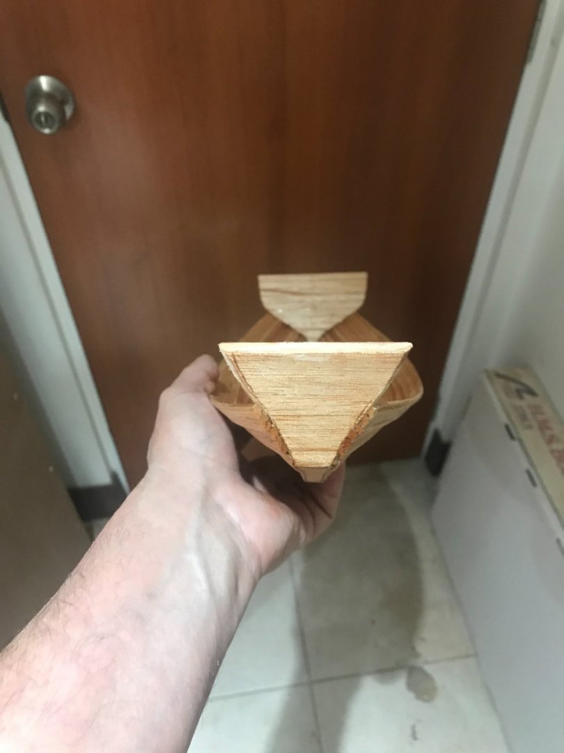
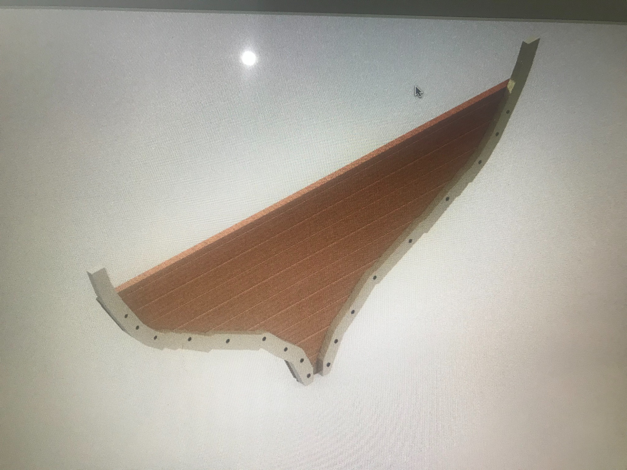
Let’s talk about the stern transom......
Binging the Nick document this is what he says.....
The stern transom
The stern transom appears to be composed of baulks of timber in three layers plus a layer of thin sheathing on the outside. The timber is fairly degraded and it may be that the inner layer has split neatly in two, in which case there are only two layers plus the sheathing. The inner layer(s) are fitted inside the main planking; presumably the ends of the strakes are fastened to this inner transom. The outer layer is aft of the end of the main planking but inside the outer planking layer. The outer planking layer is extended aft of the transom to form a kind of false counter. The outer layer of the transom has a slot cut in it for the rudder stock and is made of baulks of timber only slightly thicker than the diameter of the rudder slot, thus the slot almost cuts them in half and the strength of the transom relies on the inner layer(s). The uppermost of the extant outer transom baulks appears to have its ends cut square, so it did not extend right out to the sheathing planking at its upper face. This suggests that the outer transom did not continue above this height though there would need to have been baulks forming brackets to hold the rudder stock higher in the transom, as there are on traditional vessels of the region today
So..... Let’s try to understand this.....
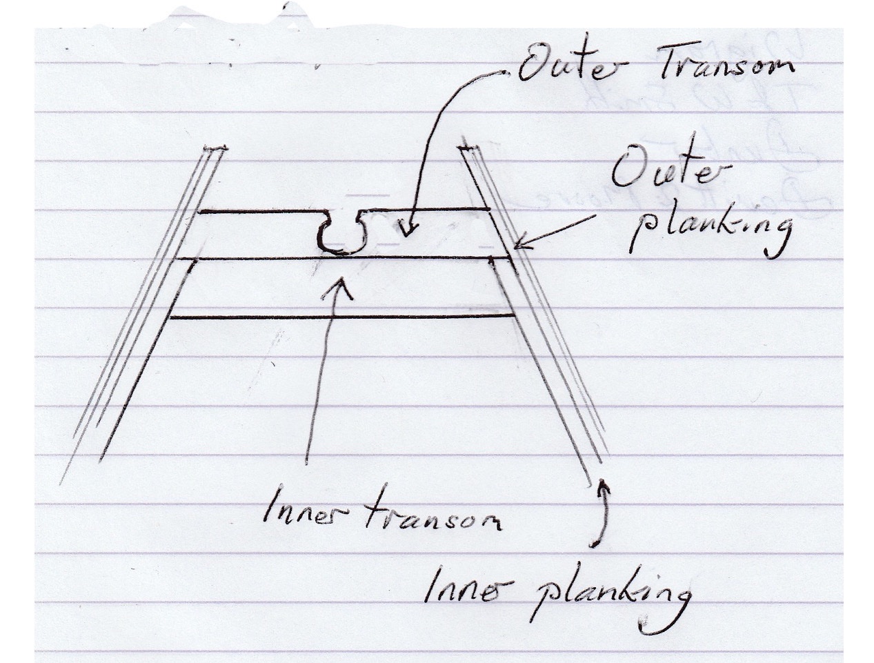
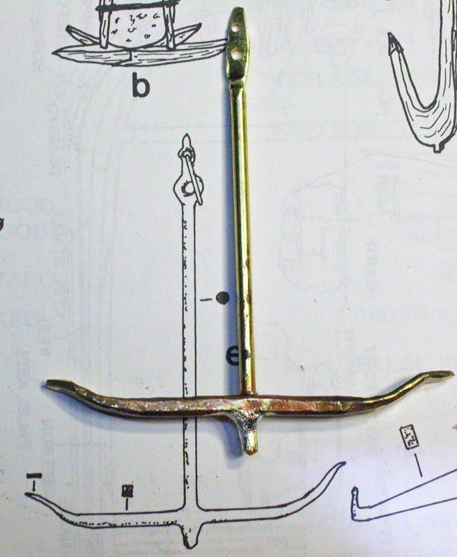
- It says that the ship has two layers in the stern transom . Where the external transom is wider. It is talking about RUDDER SLOT and let’s think about its diameter. I could not find specs about it but having in consideration its length that could be 6-7 m its should be thicker than I was expecting....... I went to this photo
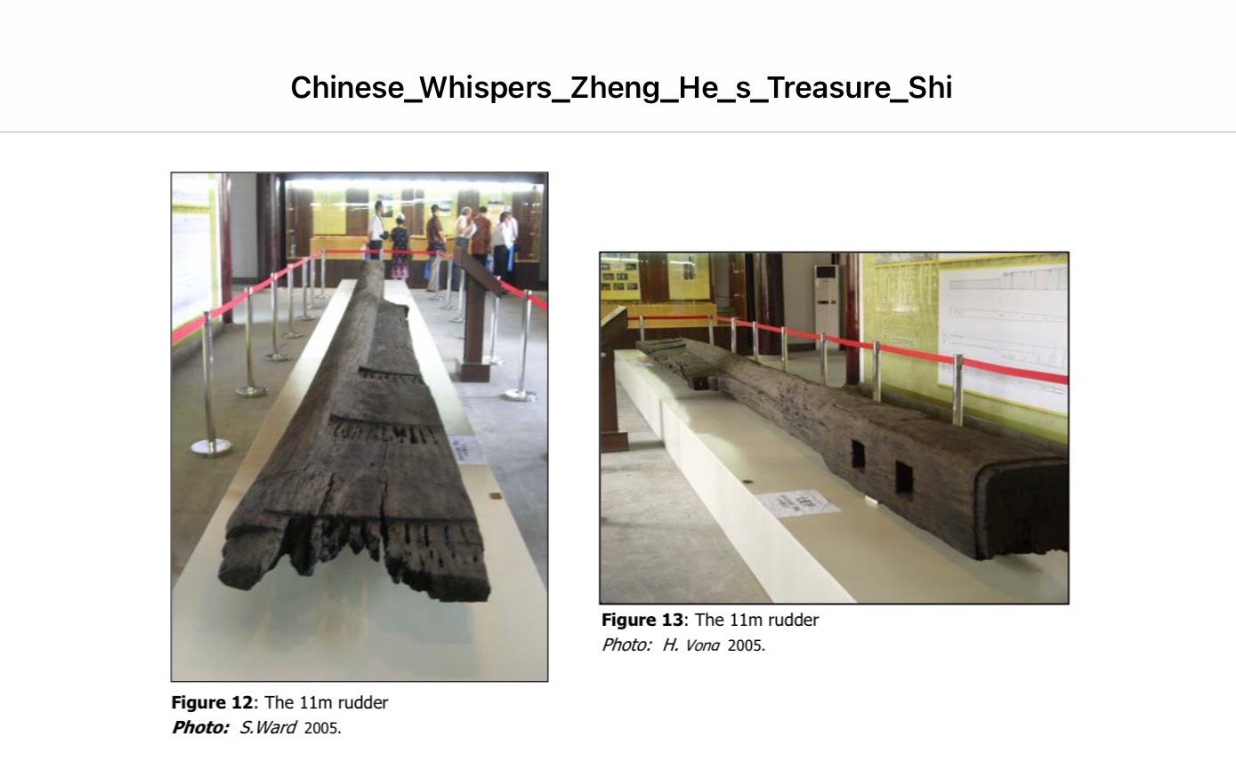
...........and having the keel with 40 cm. Then the ruder at least must have 40 cm as well. That gave me how thick should be the external transom 40 cm. And the 2 or one inner transom should also 40 cm. In total.
- This ship has two-three plank layers. The inner planks are, according with the same document 8 cm....
... The inner planking of the Quanzhou ship is 80 mm thick
So.... the outer transom should be 8 cm wider.....at the end we will end up in something like this....


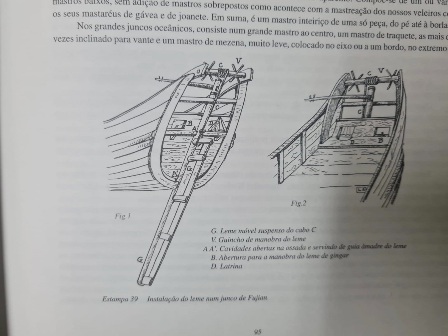
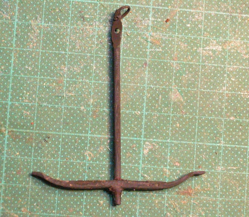
- It also says that probably has a third layer of very thin set of lumbers...... I’ll wait because the ruder in these ships has the possibility to move up and down to be able too navigate different water depths so the channel should be open, at least part of its length....
This photo is not accurate for this ship but explain really well how the rudder works.....
regards
- Cathead, rkwz, GrandpaPhil and 2 others
-
5
-
-
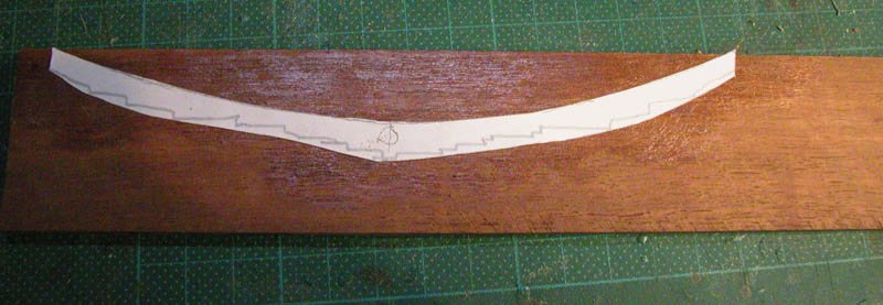
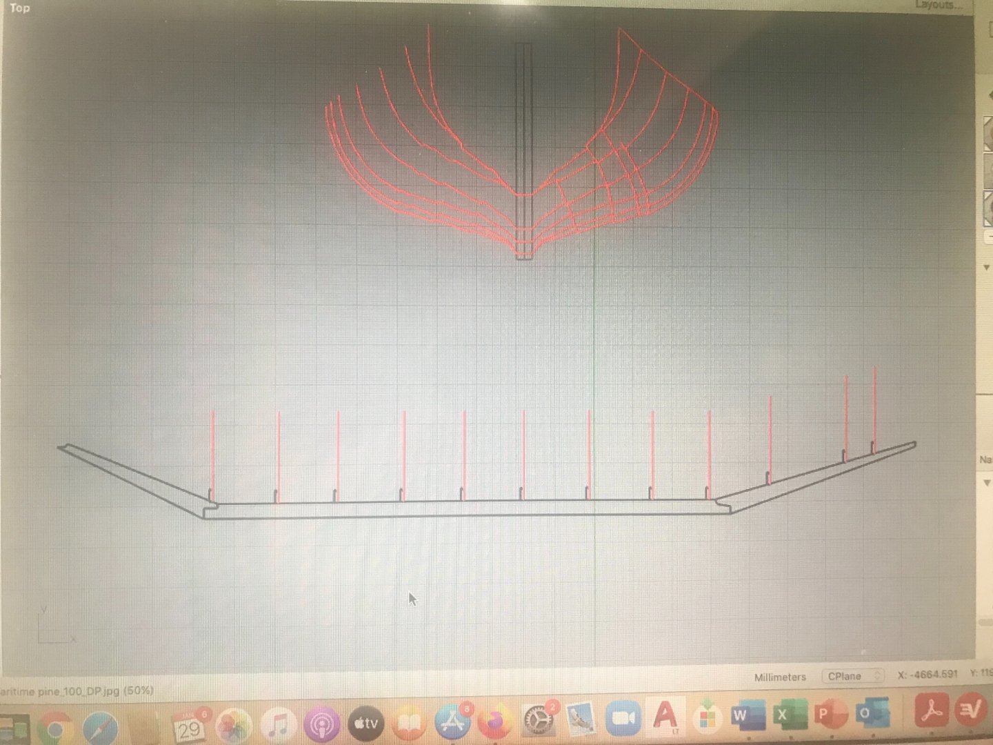
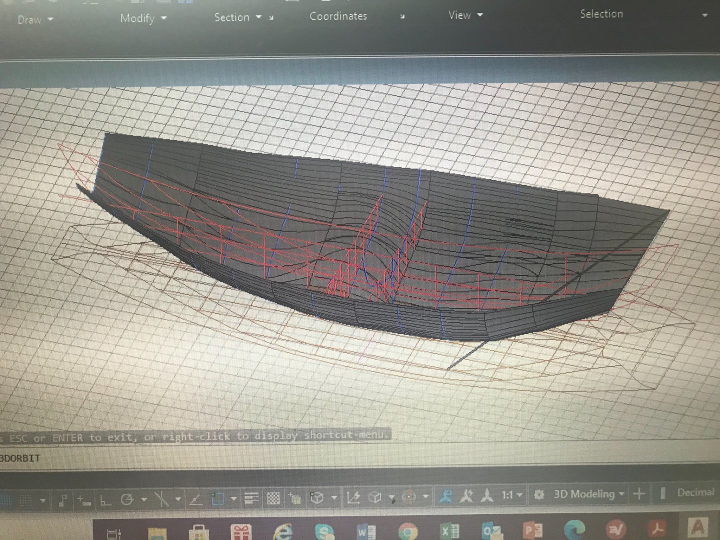
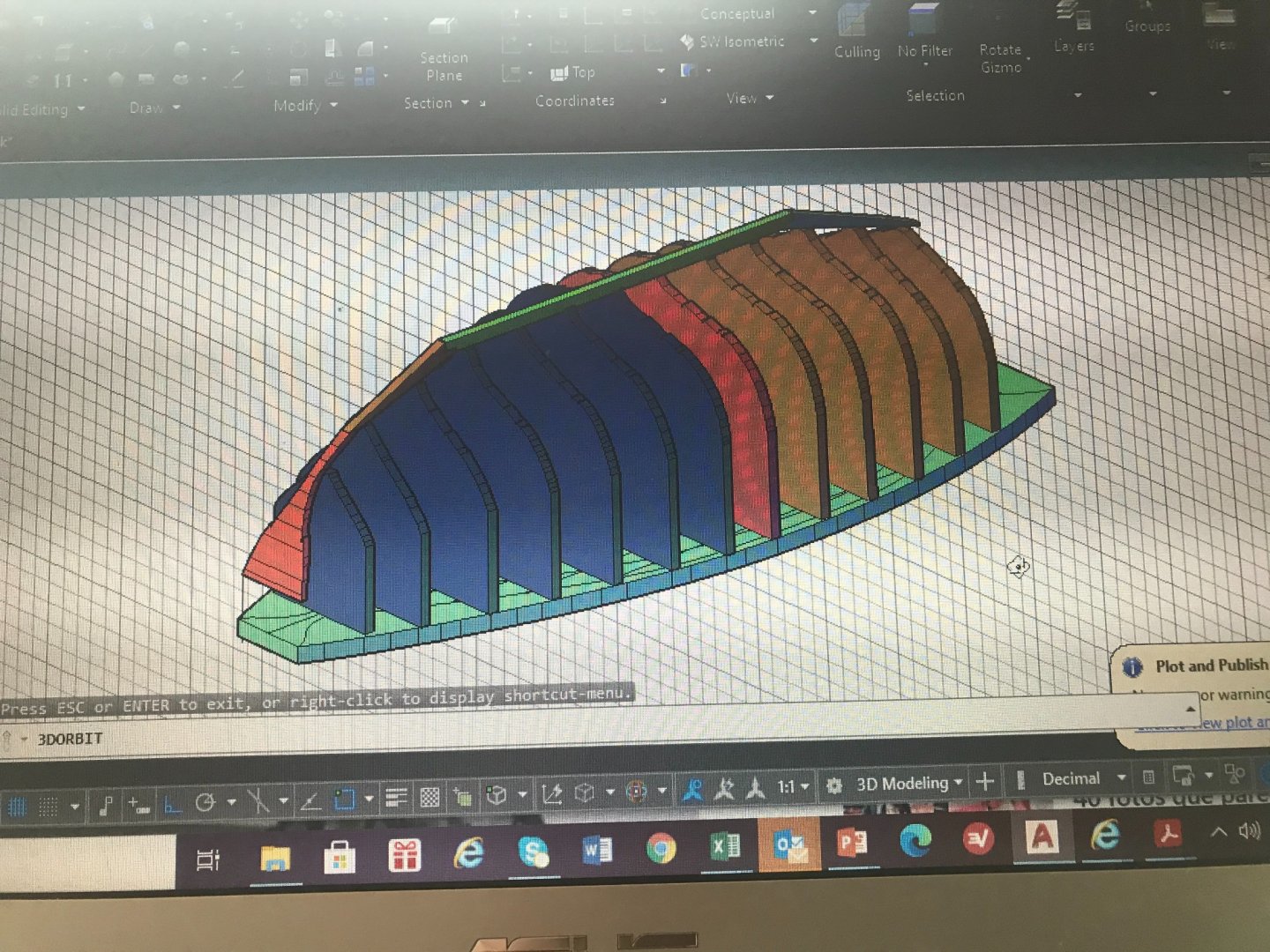
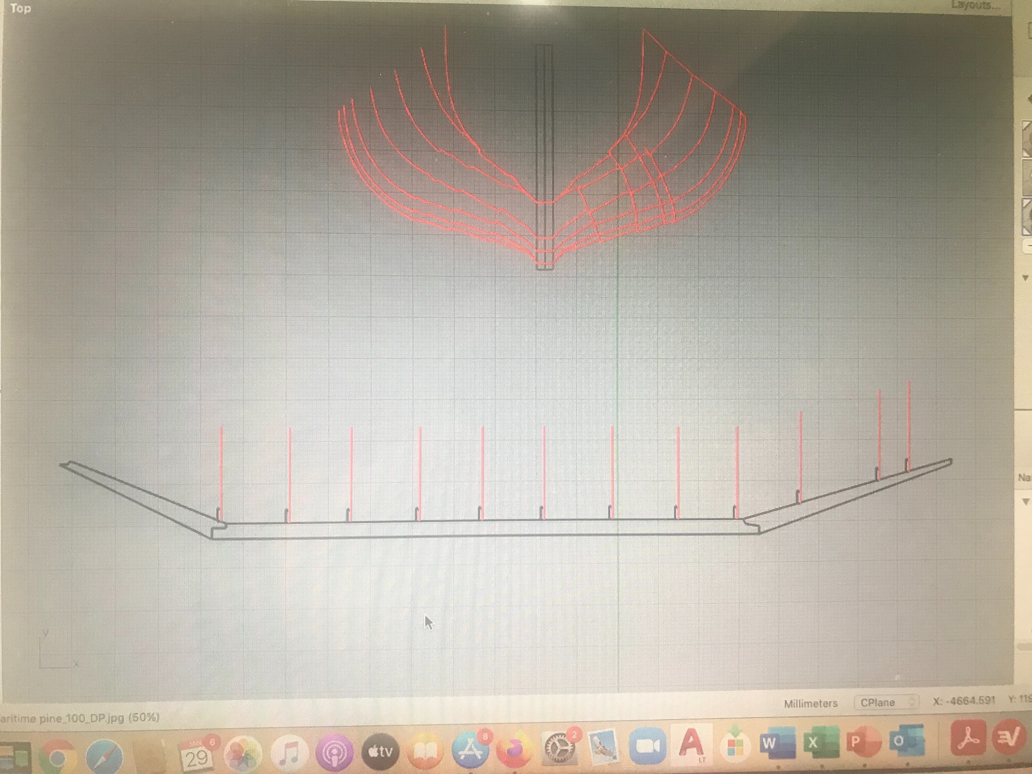
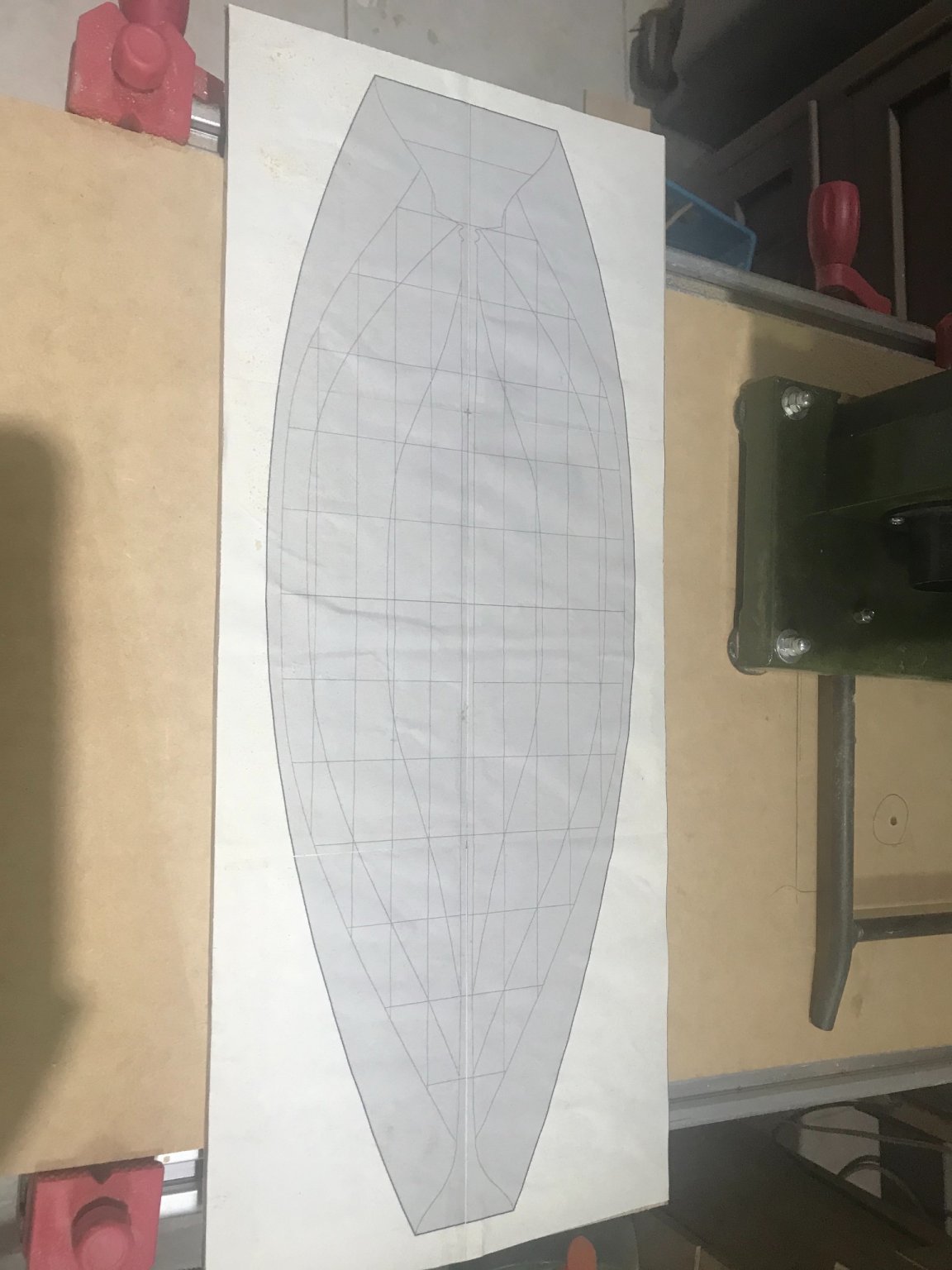
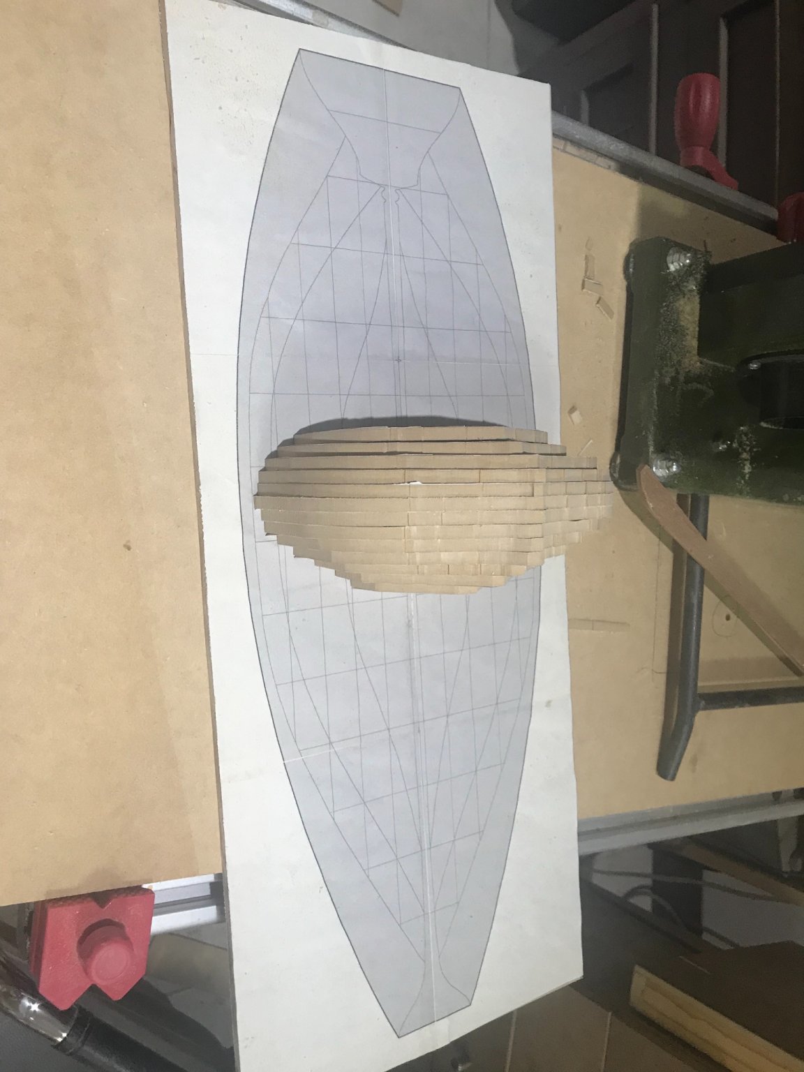
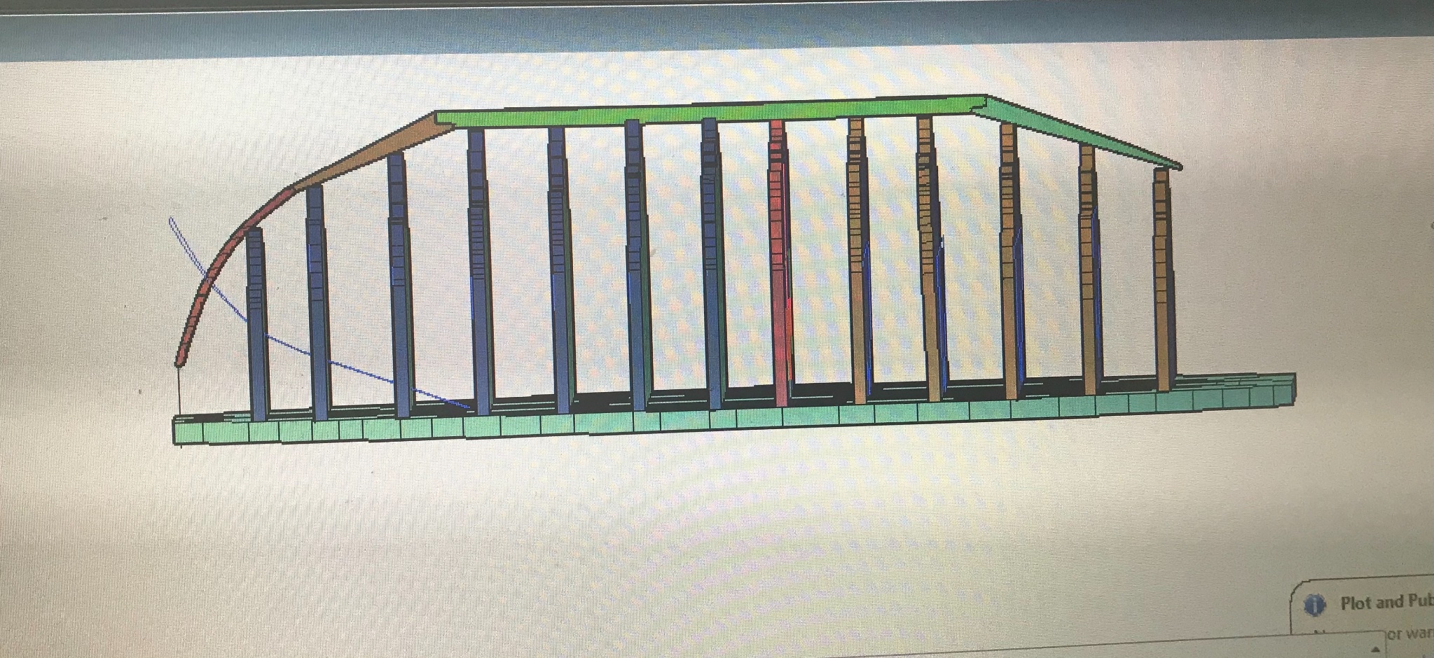
Building the mold I’ll make the base first
Then the false frames

Assembled
Interesting to see that since now the clinker planking is already marked in false frames.... let’s remember that this ship has a very special planking process.......several layers with different joint systems
- Louie da fly, bigpetr, mtaylor and 6 others
-
9
-
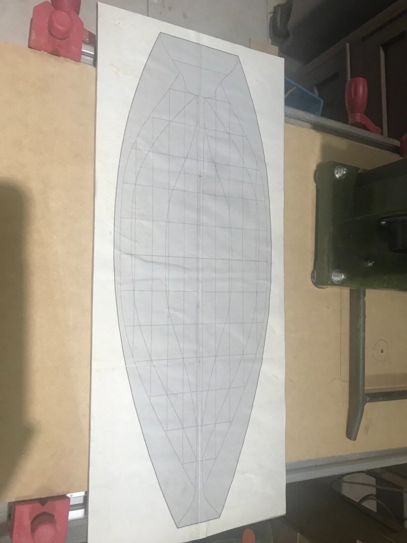
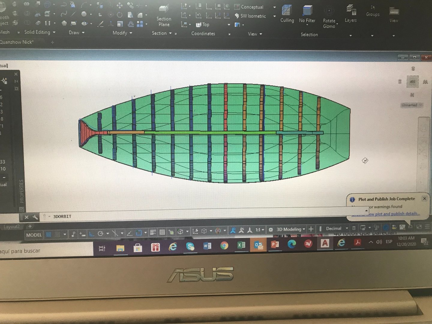
Once I sent this mold to the expert......guess what.....It was not that right.....
If you take a look the blue line in very end of the bow is what I have. The thick gray line is what should be. So I made the correction....
Now I can move forward. Since I’m not an Autocad expert..... I usually check the forms with the LOFT function.....
I realized that the false frame 4 front is not right....... son another correction...... and finally we are ready to go!!!!!
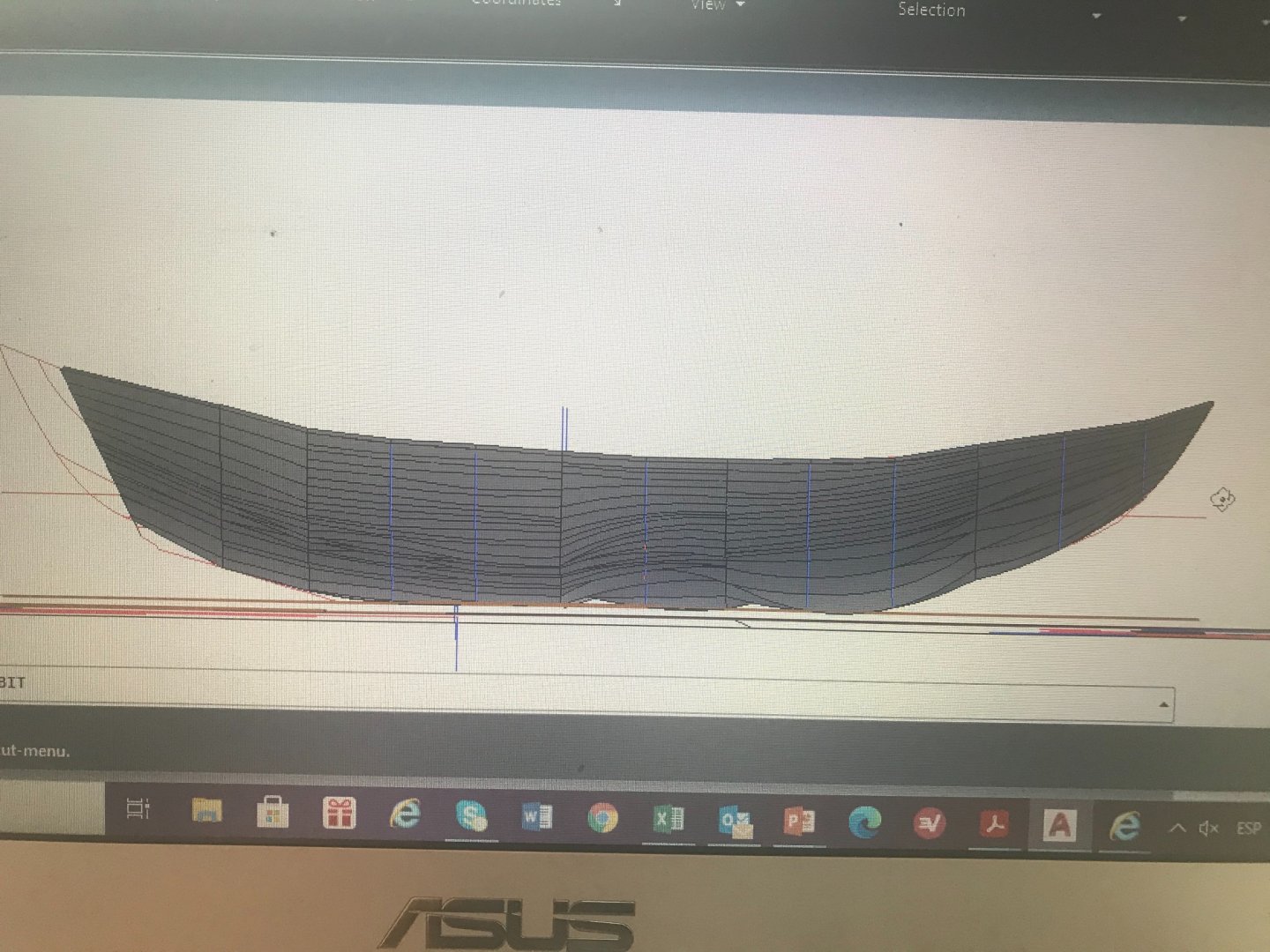


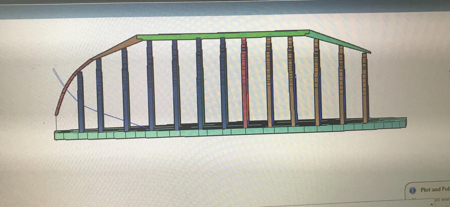
These are the false frames (all but the master). With this one I’ll move forward to build my mold.
-
On 12/28/2020 at 4:53 PM, Wintergreen said:
Looks good.
Question, will the frames overlap at the center line or will they meet butt end? With the cross beam the strength and stability will not be an issue of course.
What a good idea!!! I would never had that idea
- mtaylor and thibaultron
-
2
-
-
-
-
On 12/19/2020 at 9:20 AM, Cathead said:
What a fantastic project! I'm quite interested in traditional Chinese cultures as I work with many Chinese authors in my capacity as a scientific editor. My last scratchbuild also attempted to reconstruct a vessel about which little was known above the hull, so I have some appreciation for the complex research and decisions involved (though yours will be far more difficult).
I'm struck by how much those planking cross-sections look like a clinker-built Viking longship. Obviously the bulkheads don't match, but the profile is quite reminiscent.
Not at all!!! These kind of projects are all the same difficult. But since you already was “here”. Any help will be appreciated ☺️
-
Thanks to you all. I hope we all (included you all) will get there. I decided to start with the hull forms decision so here we go again.....
Starting from this.... the Nick projections ( he has been really clear about the sails...they must be squared not like he suggested in this picture)

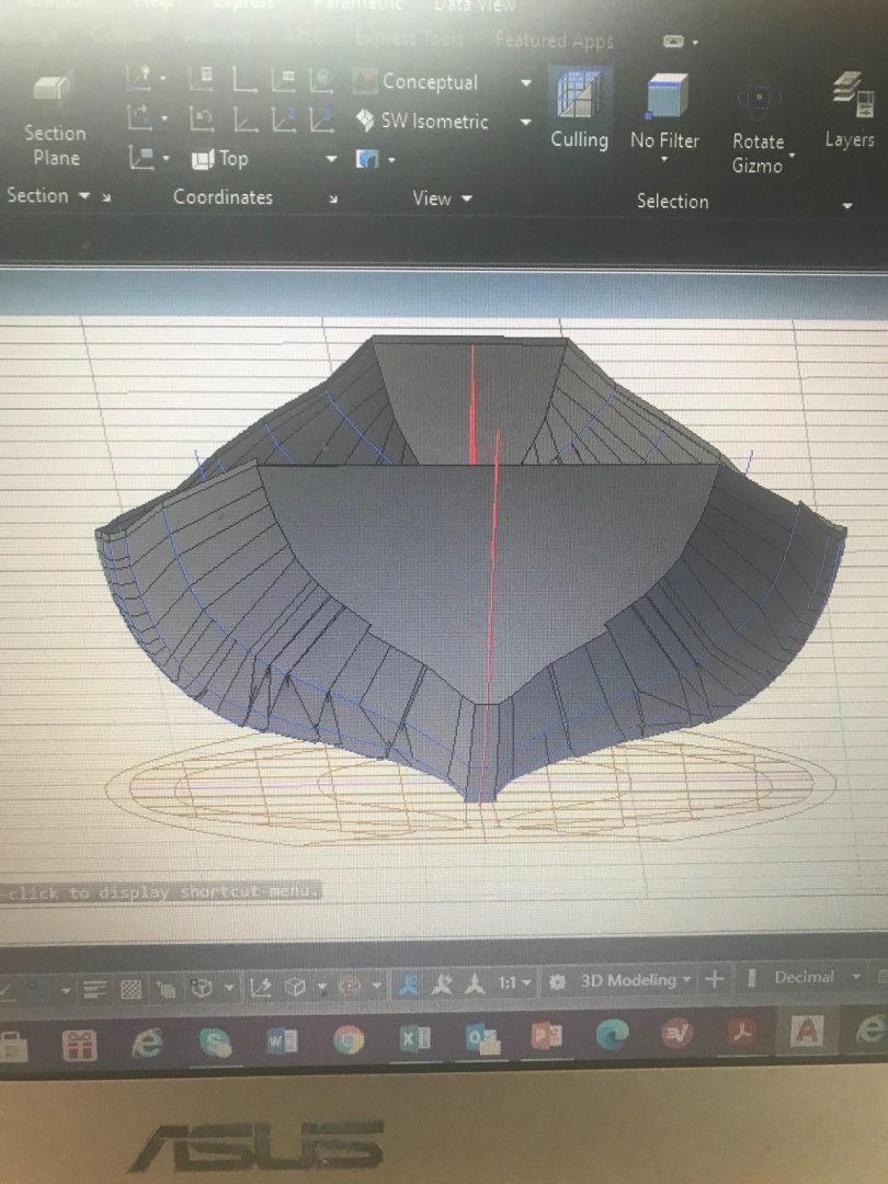
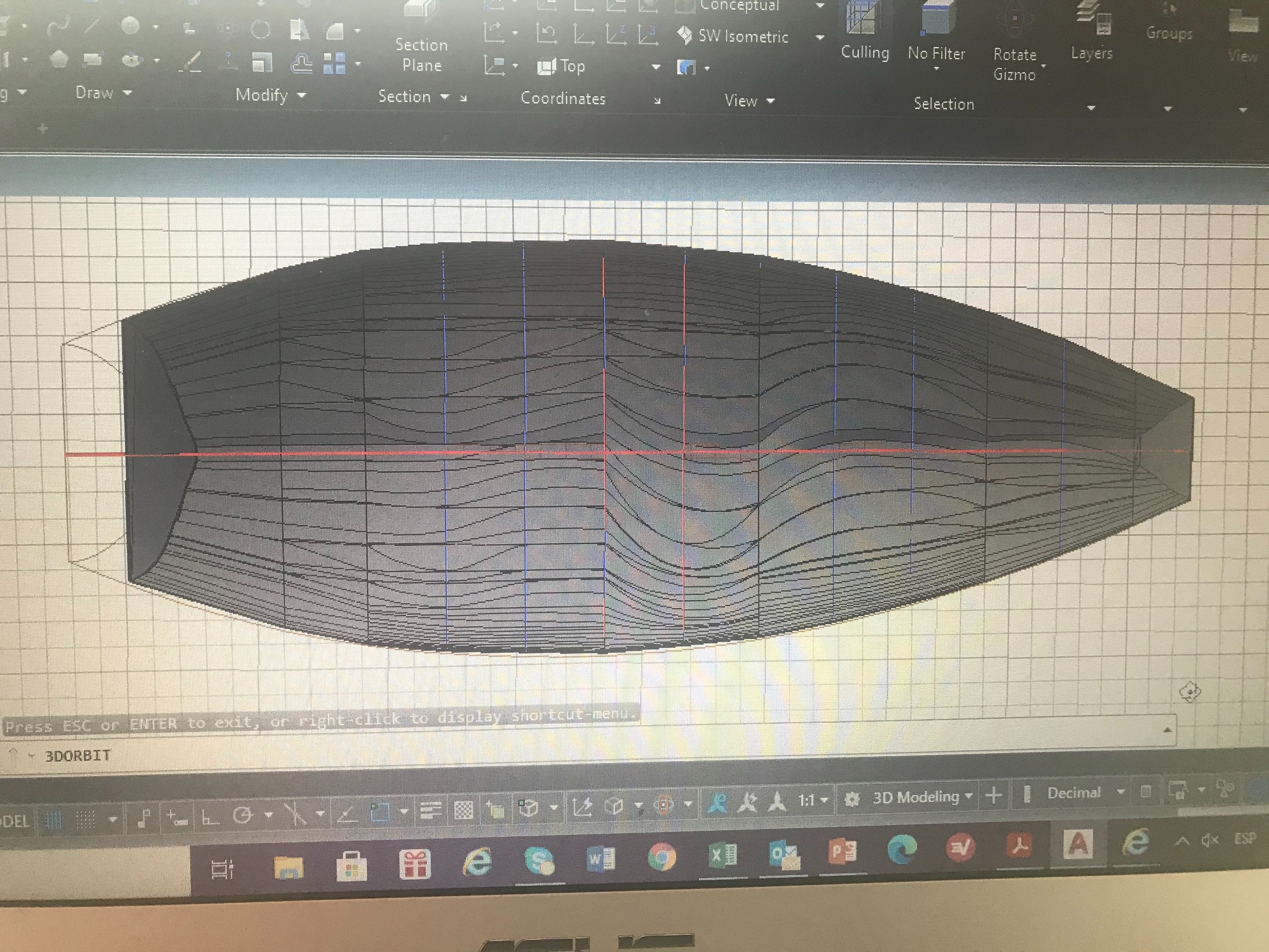
Imported to Autocad and “built” the hull.....
This is giving me the Idea about the hull, bow and stern. Again... this is a ship that no one has seen before.
I have to count on the junk construction methodology ..... I am really surprise by the “plank first frames after”. We can see that in Egyptian, Vikings and now the Chinese. Having this in consideration I decided to build a “mold” upside down, also using the Nick plan, I went to the Autocad and....
As you can see I “installed the keel already”. And also I was able to “install” the bow form. The stern is something that I still thinking about. But when you see the picture above, you can bring the conclusion that the stern had like two levels (I’ll figure it out later).
Let’s talk a little bit about the keel.....”The keel is constructed in three parts: the forward and aft portions are made of pine, and the central member is made of camphor wood. The forward and aft keel portions are scarfed to the central member. The central member is 12-57m long by 420 mm wide and 270 mm deep”.......
There are some “imperfections” that need to be fixed in the construction phase.
We are getting close!!!!! To start, but unfortunately the holidays are going to stop my job a little bit.
By the way!!!! I have not seen my kids (Seattle, Atlanta and Carmel Indiana) in almost 20 months, We are traveling this coming Tuesday from Colombia!!! Very exited and .... we know is not the best time to do it. God help us to be safe and good health.
-


Quanzhou Ship by Schrader - 1:54 - Chinese Junk
in - Subjects built Up to and including 1500 AD
Posted · Edited by Schrader
Let’s read what Nick says in his document.....
“Ju-nails or Gua-ju (iron cramps)
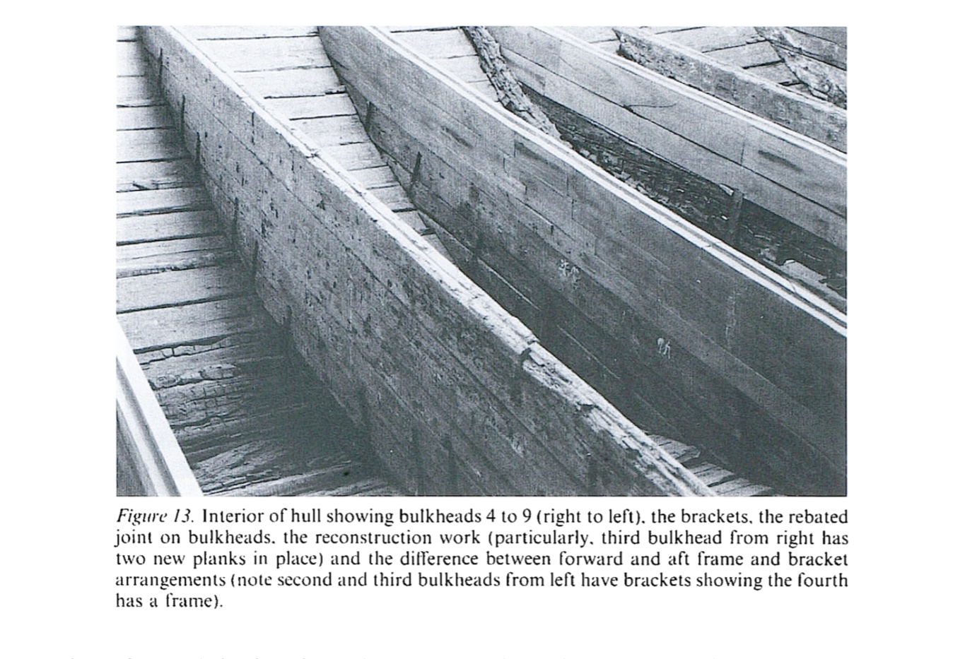
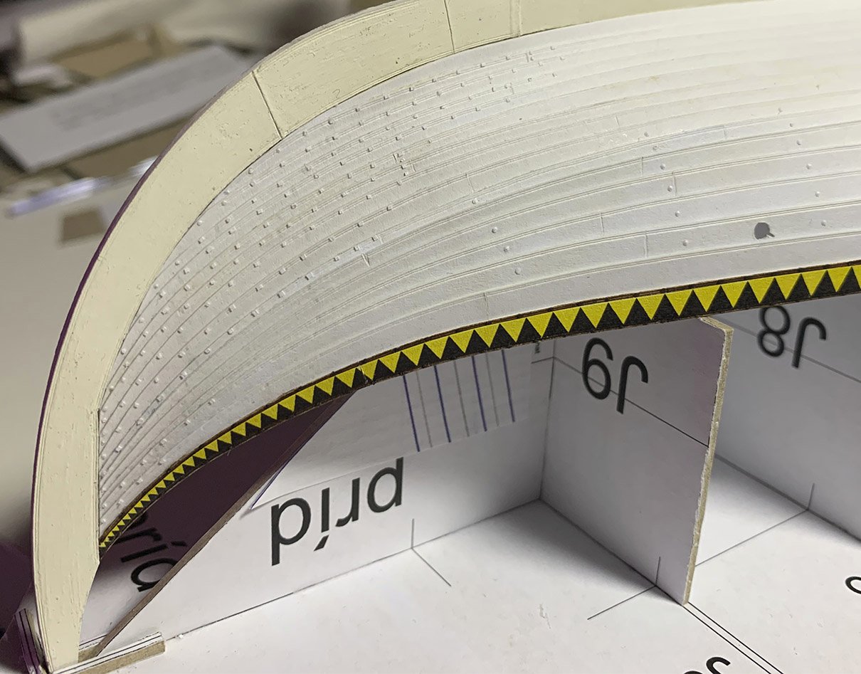
The main planking is fastened to the bulkheads by L-shaped metal brackets gua-ju or ju-nails (Xu Yingfan, 1985 and Li Guo-Qing, 1989). The brackets are recessed into the bulkheads, and the feet of the brackets are recessed into the outer face of the main planking according to Museum of Overseas Communication History, (1987: 20). The brackets vary in length from about 400 mm to 550 mm and they are all about 60 mm wide. They seem to have been not more than about 7 mm thickness, but given the entirely oxidised condition of the remains of the brackets this can only be determined from the width of the slits where they passed through the planking. Most brackets are aligned within about 7–8 ̊ of normal (90 ̊) to the plank that they fasten, when viewed in transverse section; but a few are as much as 10 ̊ from normal. This suggests that the ends were bent over in situ, since if they were pre-bent all brackets could be expected to be bent at the same angle (about 90 ̊) and to lie more or less precisely normal. Like the pattern of plank butts, the positioning of the brackets is symmetrical port and starboard (except for an extra bracket in strake ten at bulkhead eight on the starboard side). The positioning of the brackets is tabulated in figure Y. The strakes immediately below the clinker steps (strakes 5, 8 & 11) have only one or two brackets connecting them to the bulkheads throughout their length. Whereas the strakes immediately above the steps (strakes 6 & 9: too little remains of strake 12 and the bulkheads at the height of strake 12 to constitute a useful sample) have the greatest number of brackets—thus these strakes clamp in place those immediately below them.
The slits where the brackets pass through the planking show that the brackets were only about 5–7 mm in thickness, but in a few cases they were recessed as much as 12 mm into the bulkhead because the slits were not always perfectly positioned in relation to the face of the bulkhead with which they were required to align. This suggests possibilities about the construction sequence. The slits could have been cut before the bulkheads were fitted since the bulkhead positions were predetermined to align with the plank butts.”
Regarding their distribution, there is mentioned above the figure y
And this is the way I decided to move forward.
First decision was going with metal brackets and the second was trying to the bulkheads with no glue, just using the “real” method the Chinese people suppose to build it.
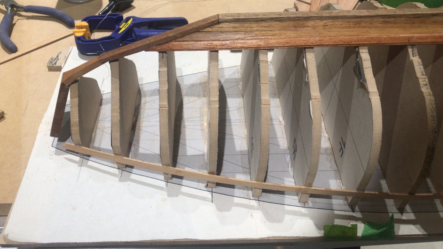
The Bulkhead number 6 has 4 Brackets in strakes 6 and 9 in each side
The bulkhead number 7 has 4 brackets in strakes 2, 4 , 7 and 10 in each side
They have no glue!!!!!
Let see a couple of pictures......
Note the little hole in the bulkhead above the keel...... this is to allow the water flow. We will see also that this particular ship had a
Lime putty, wash or plaster
Everywhere on the hull, inside and out, there is the remains of a layer of lime. The use of this lime is discussed in some detail by Li Guo-Qing (1989). It is in all the seams, behind the brackets, between the layers of planking, and it plugs the tops of holes for fastenings. It is only the lime plugs that show the position of nails used to fasten timbers such as the half frames and the knees at the scarfs in the keel; and it is possible to trace the original outline of the degraded half frames because of the thick line of lime that collected between the upper face of the frame and the face of the bulkhead. Probably the lime in the seams and in the fastening holes, and perhaps that between the layers of planking, was applied as a lime putty, as it is today in the traditional boat and shipbuilding of the region. The oil used to make the putty is tung (t’ung) oil extracted from the nut of the t’ung oil tree (Aleurites fordii [Li Guo-Qing 1989: 279]) In the Song Dynasty, Quanzhou was known as Ci Tong or ‘Tung Harbour’ because of the many tung oil trees in the region (Pers, com. Wu Chunming)
So.... it is time to think about it....