


Schrader
-
Posts
304 -
Joined
-
Last visited
Content Type
Profiles
Forums
Gallery
Events
Posts posted by Schrader
-
-
How are you going to solve the bow/stern curves?
- Louie da fly, mtaylor and KrisWood
-
 3
3
-
It is unbelievably. But for the scale we have to work, that would be “impossible”. But take a look about the frames they are not precise...... they just are made to keep the form and give the hull the strength it needs.
this is really valuable information for my project. I hope you don’t mind if I use it. As you can see in my Egyptian, I’m trying to replicate the way those ships were built.
Thanks a lot
- Larry Cowden, Louie da fly, KrisWood and 1 other
-
4
-
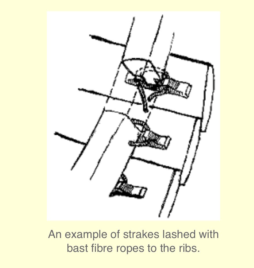
20 minutes ago, KrisWood said:
That's a very nice illustration! It does miss one key point of the Oseberg ship's construction though, and that is the plank clamps used to lash the frames to the planks. Here is a detailed article with lots of photos of the process used in building Saga Oseberg:
https://osebergvikingarv.no/osebergskipet/rekonstruksjonen-av-osebergskipet/spanteplassering/
Any Viking ship that used plank clamps would have been constructed in the same way. For example the Gokstad ship used the same method. The only difference was that the Gokstad ship used tree roots instead of baleen to lash the frames to the plank clamps.
- KrisWood, Larry Cowden, mtaylor and 1 other
-
4
-
Hello.....
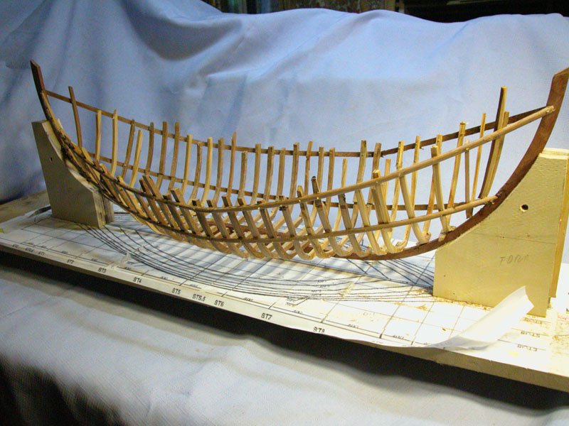
Having in my mind to have one Viking after having one Egyptian..... Take a look of this picture..... is a recreation of the Viking shipyard....
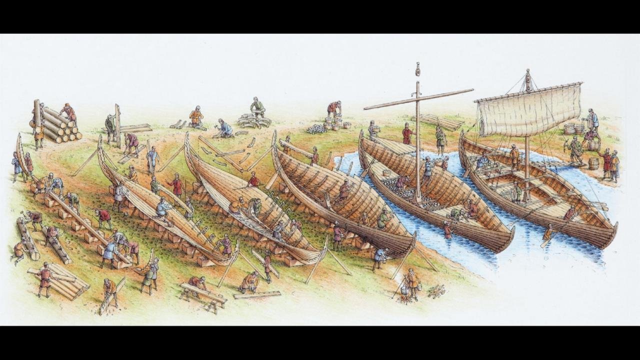
You will see how they just put the frames once the ship is started.....The frames are made after all to adjust to the real shape of the clinker hull
- Larry Cowden, bigpetr, Louie da fly and 4 others
-
7
-
Dioramas are really the "next" step for us. Go ahead!!!! but just keep in mind...... Dioramas never end we have to abandon them 😀😀😀
- mtaylor, Keith Black and Louie da fly
-
3
-
-
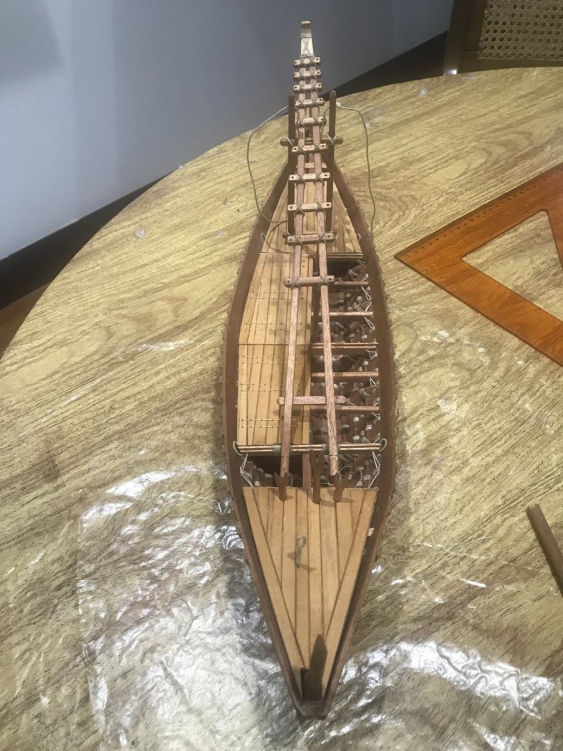
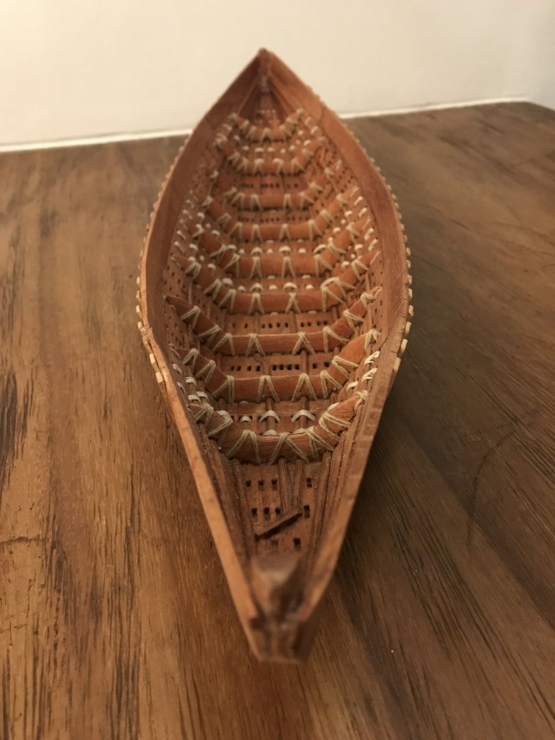
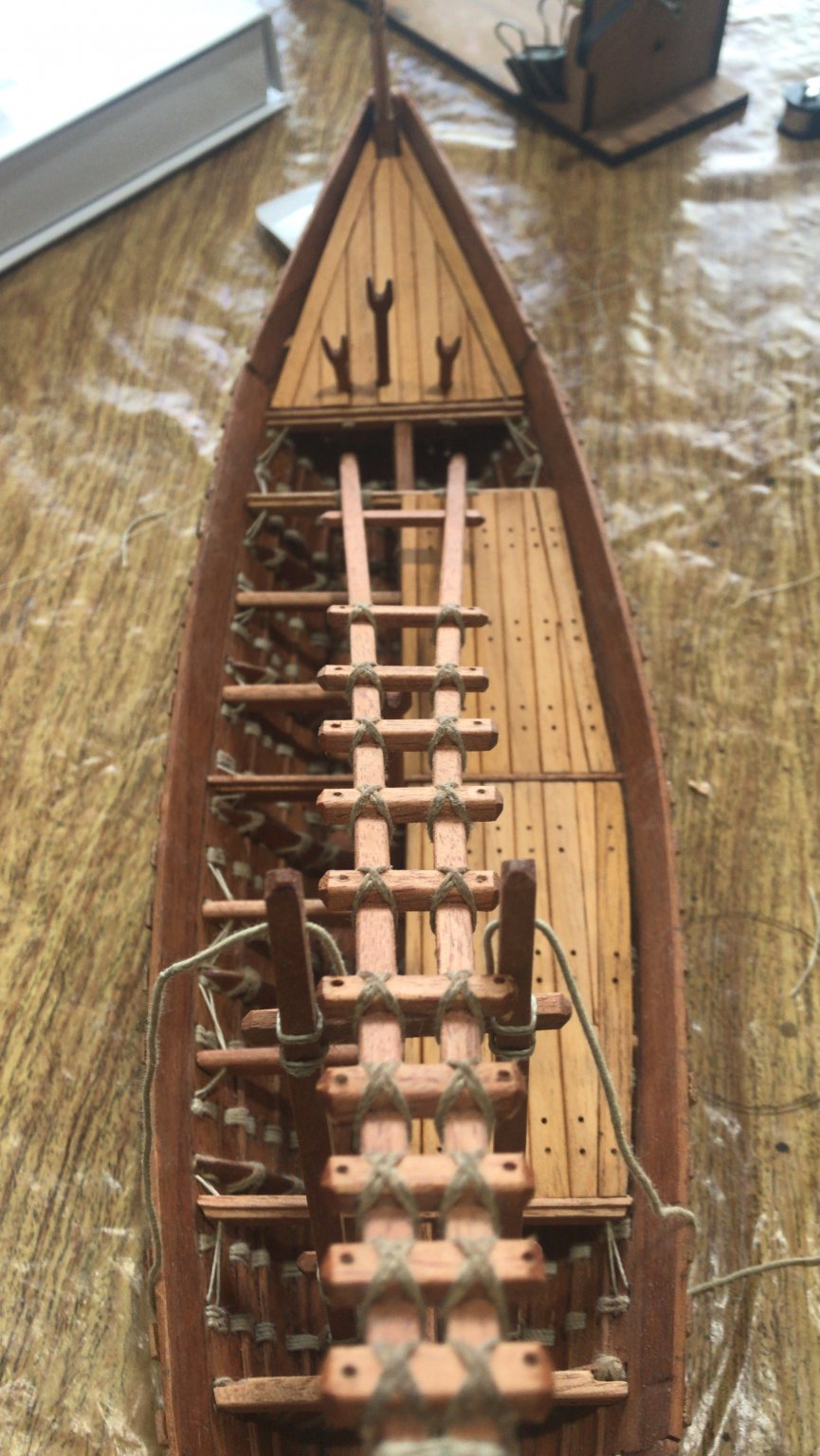
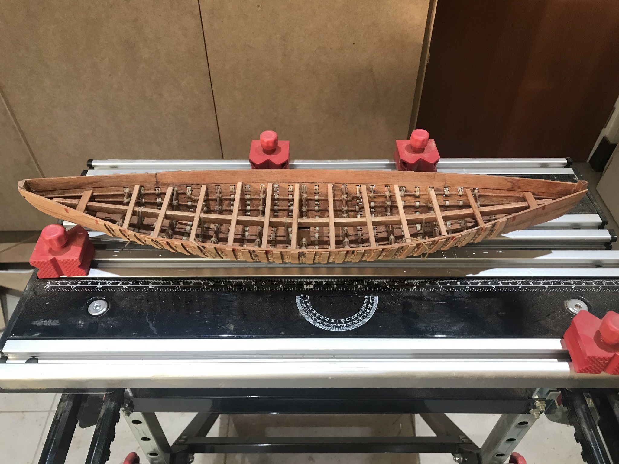
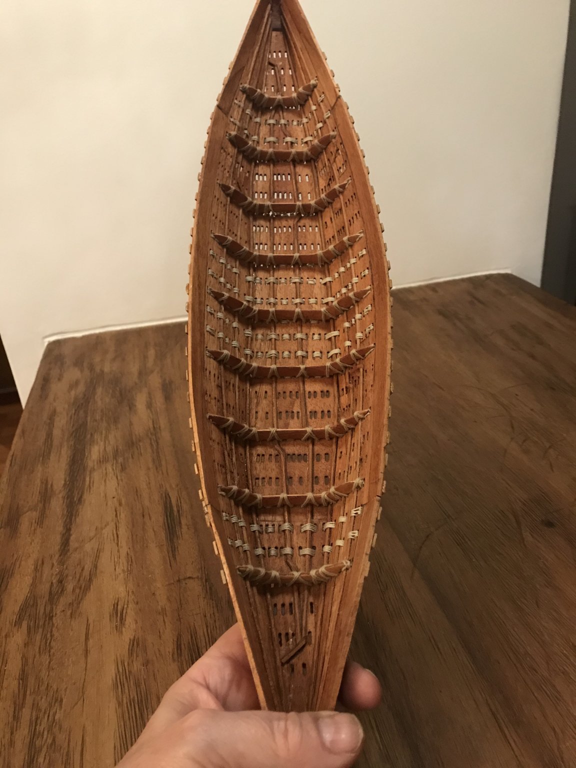
Let’s keep going with the advances.....
I’ve been working in the deck. The central zone will be full removable and I have done just half of it. It will allow all the hull sewed been sewing.......
It is sewed also.... at the same time I’ve working in the bow and stern deck but these are just “presented” since I need to work in the external hull, finish the hull sewing...
And then they will be fixed/sewed.
Take look how it is looking so far.....

-
-
On 7/19/2020 at 2:27 AM, woodrat said:
Thanks, Steven.
Some progress on the vessel. The framing is compleat. I have deliberately made the framing a little rough to match the roughly adzed appearance of the original. I think it would look odd if smoothly machined frames were depicted.
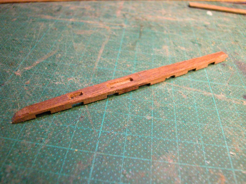
The mast-step.The larger slot is for the mast and the smaller slot is for a supporting stanchion for the forward sloping mast.
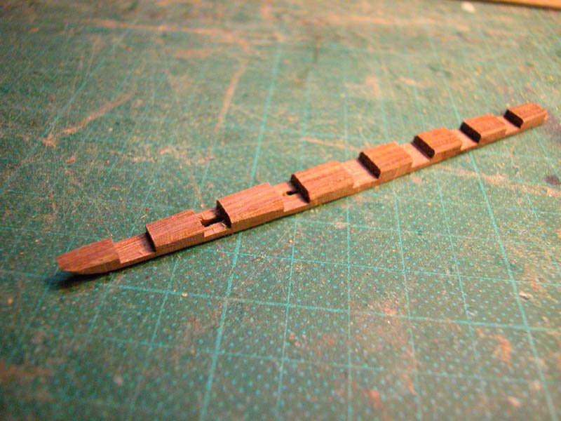

The mast-step timber is keyed into the frames.
The first and third wales are in place
Cheers
Dick
Now we are talking!!!!! Really good decision. We all have been to the same “process”.
Good job
-
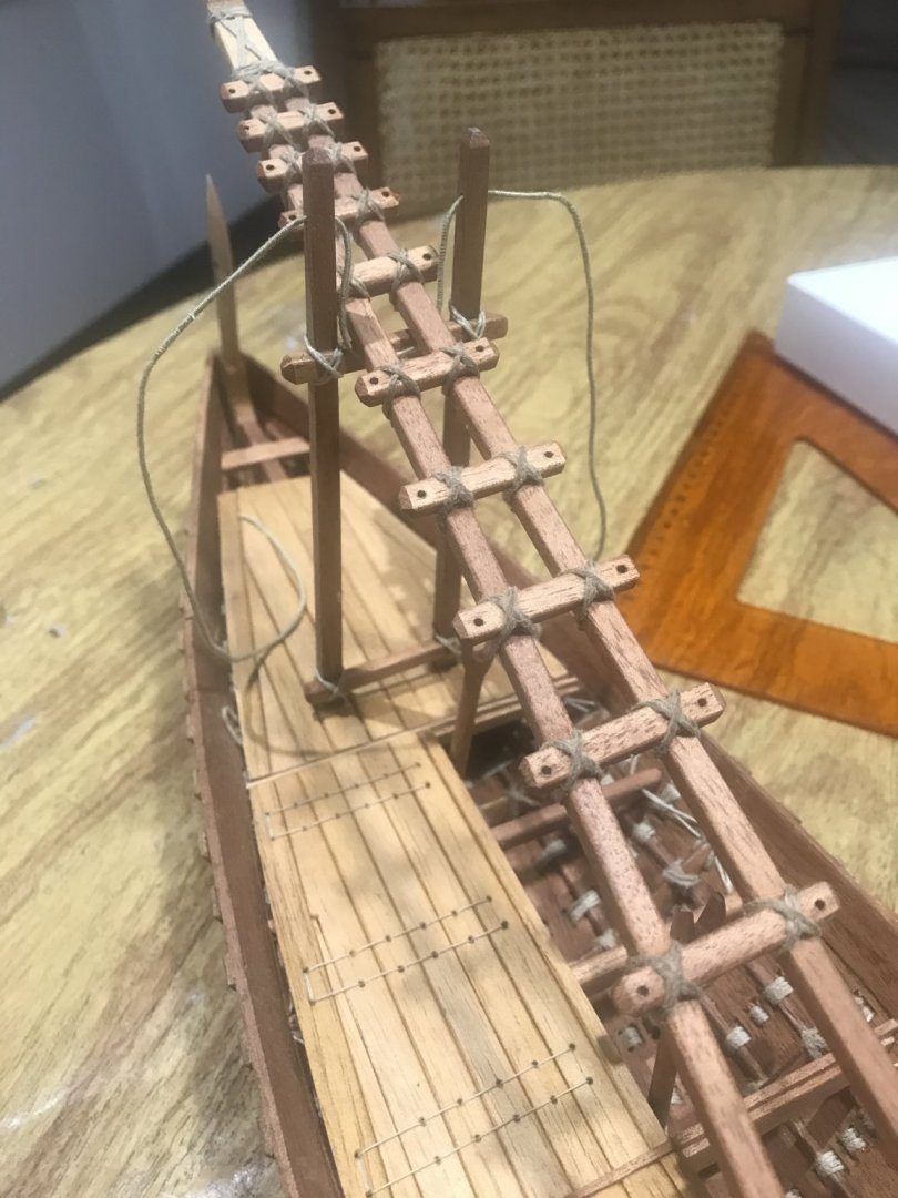
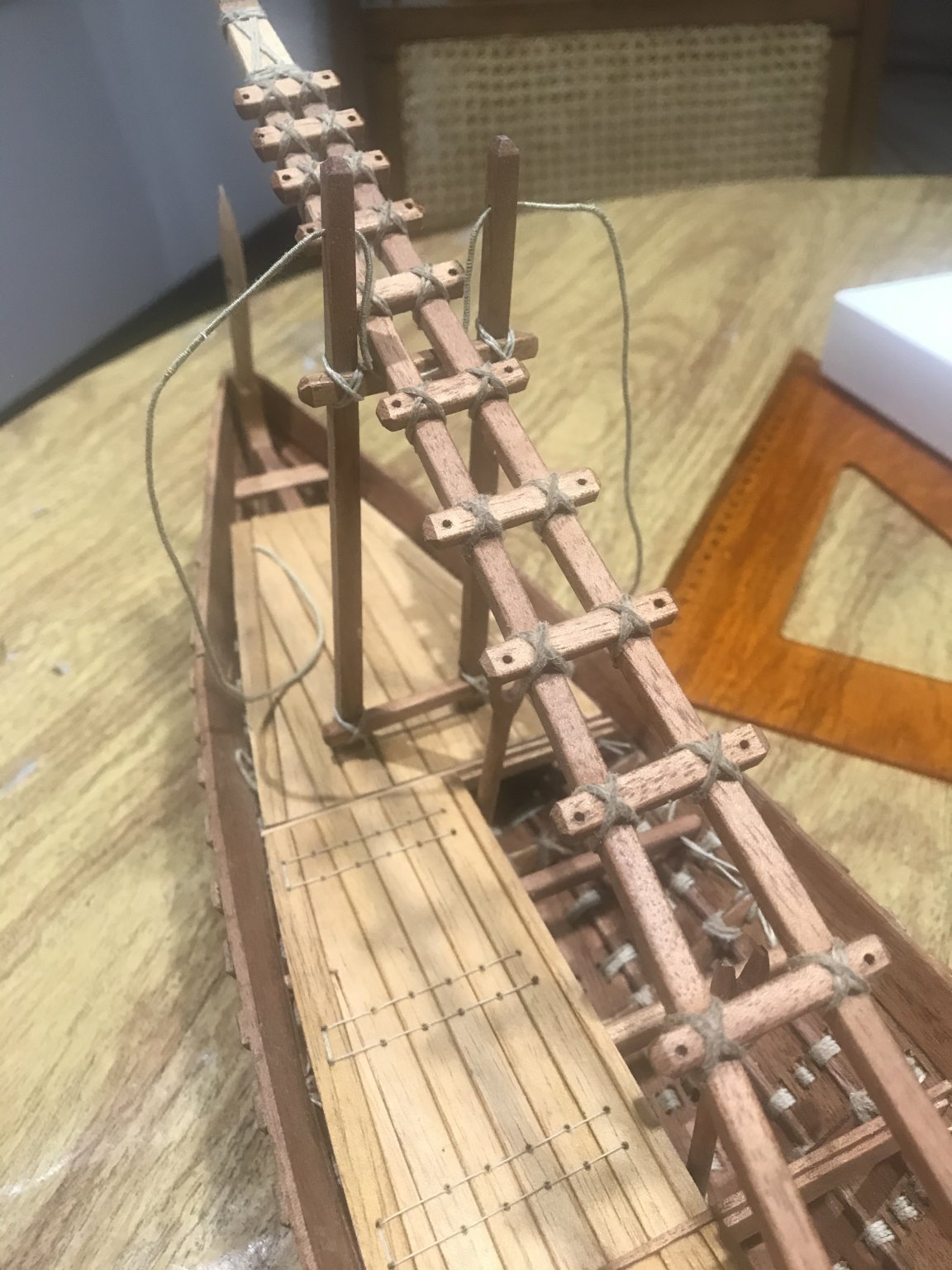
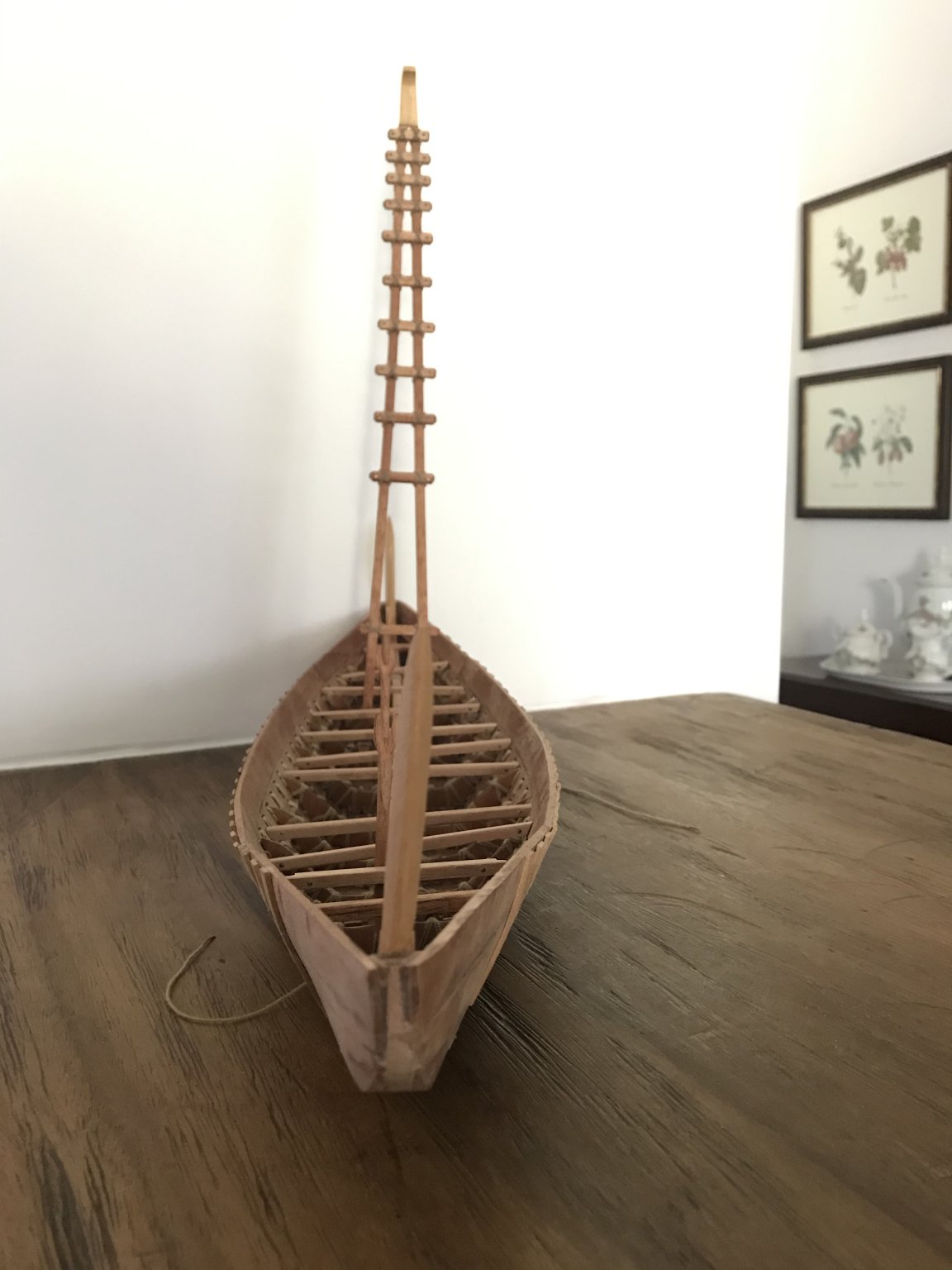
Some pictures with advances.....
It has the must of the beams and the mast “support”, when it is not with sail.....
SO FAR!!!!! JUST GLUE IN THE HULL!!!! ALL THE ELEMENTS HAVBE BEEN TIED UP. ....😀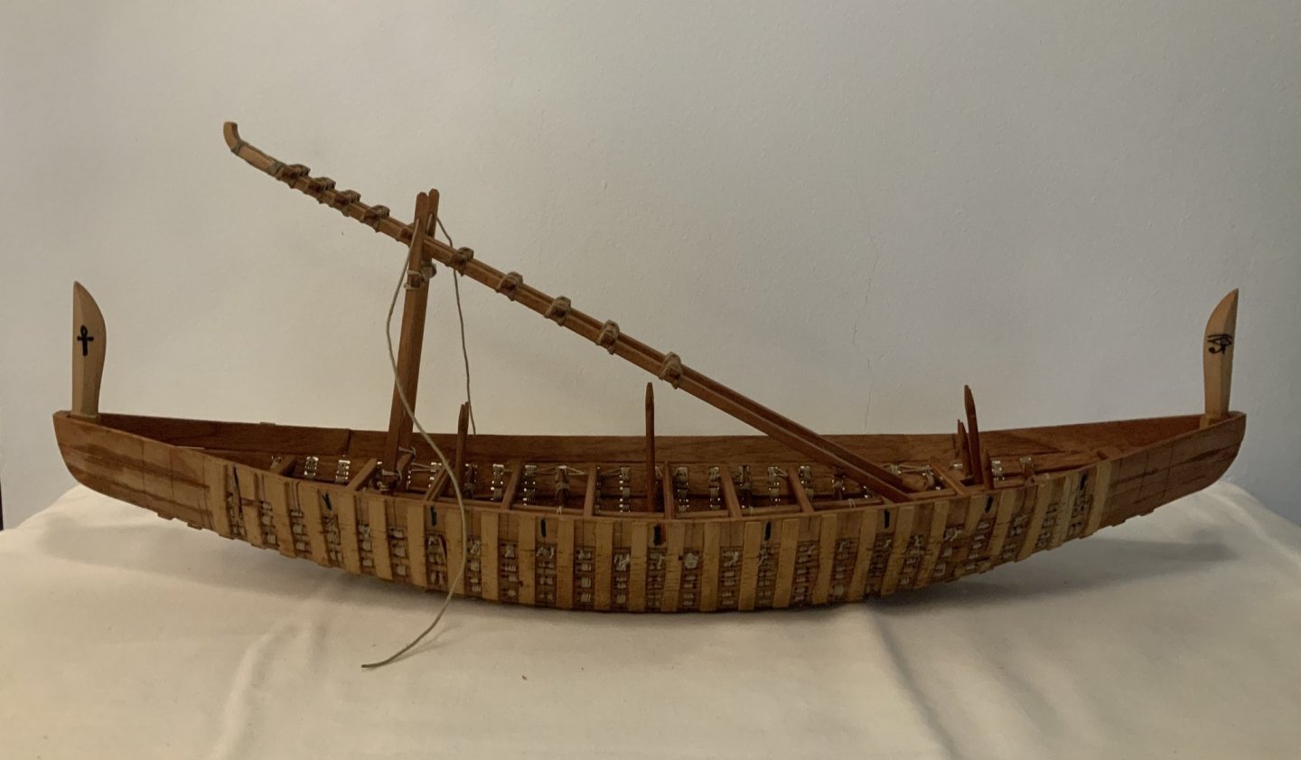
- GrandpaPhil, mtaylor, druxey and 6 others
-
9
-
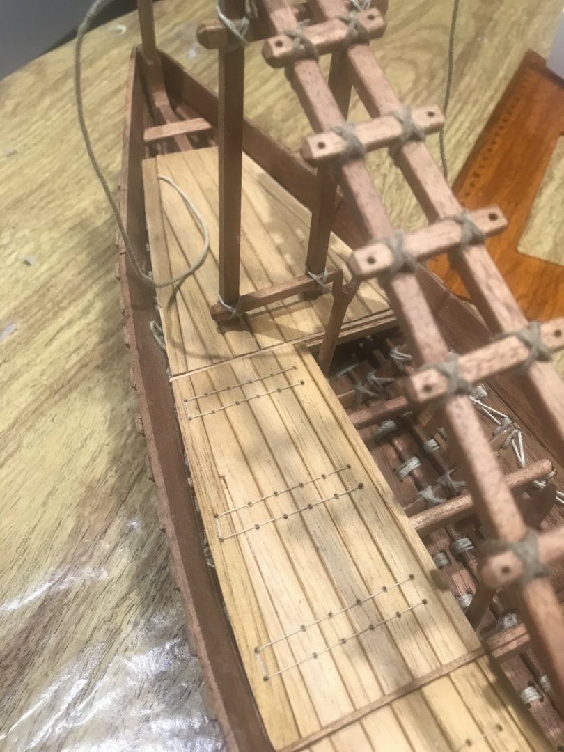
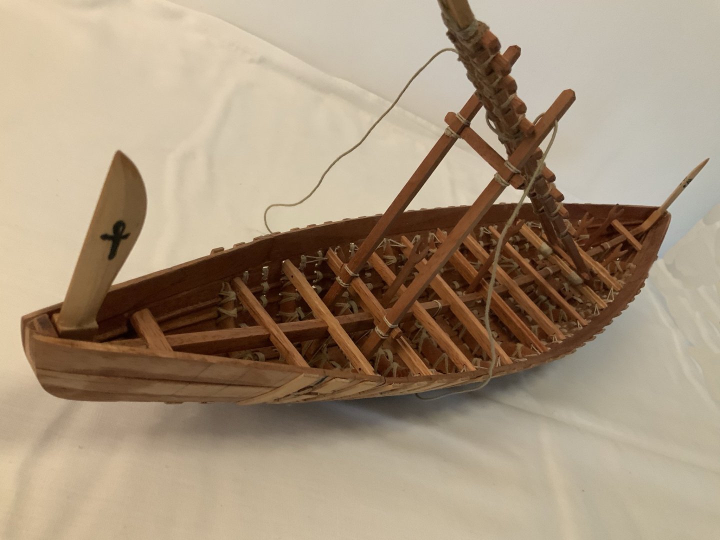
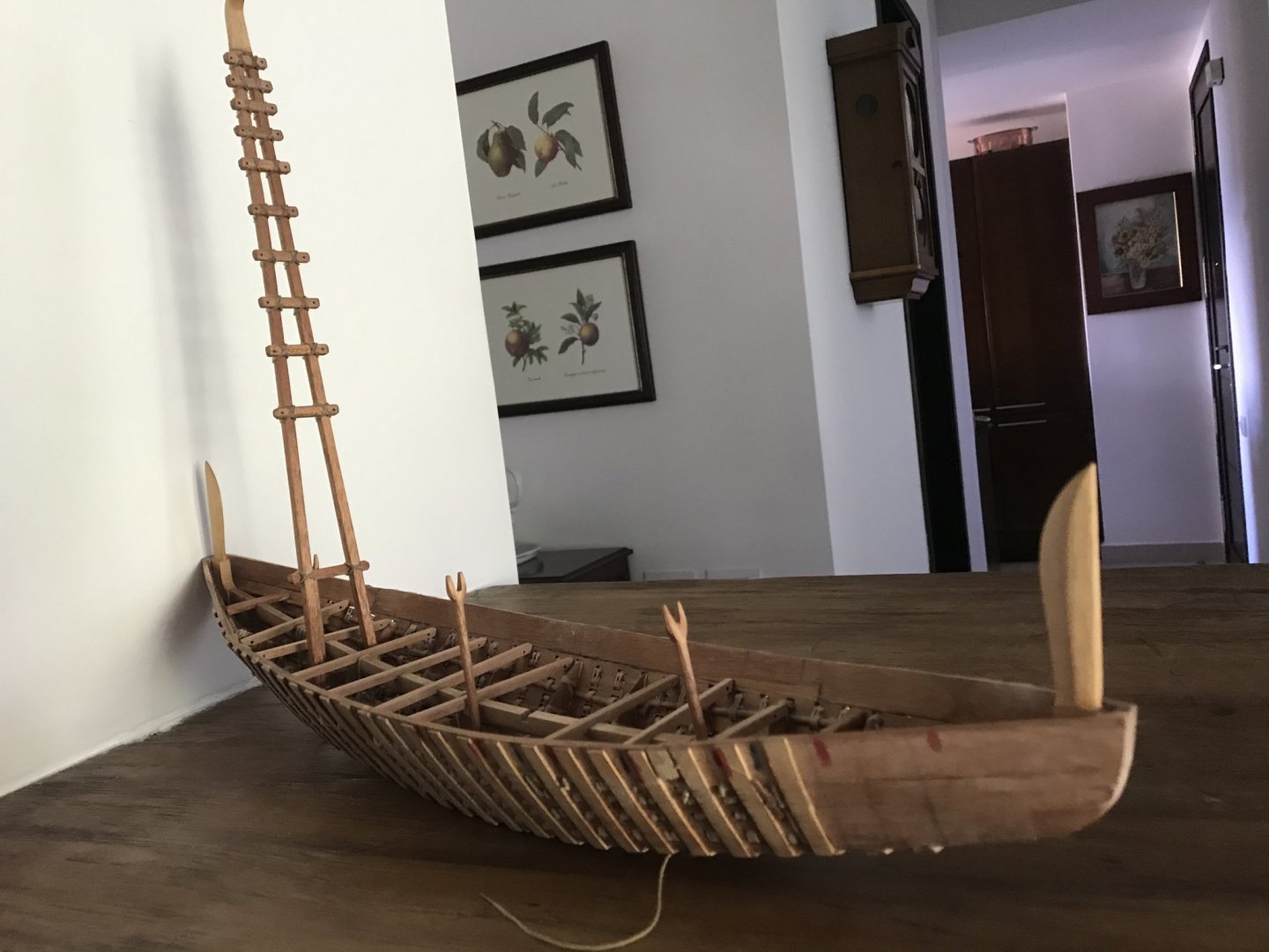
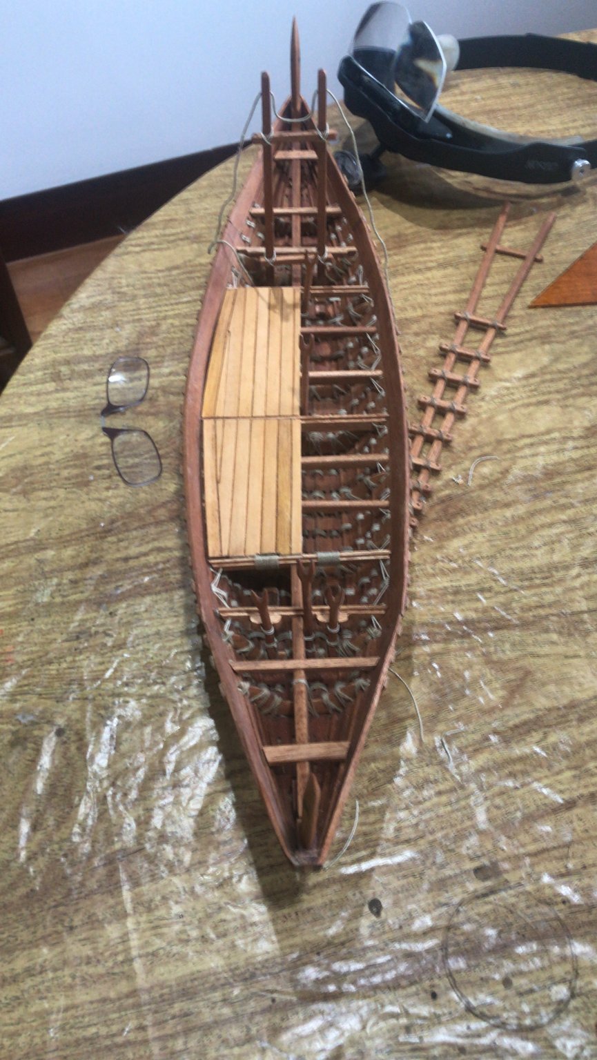
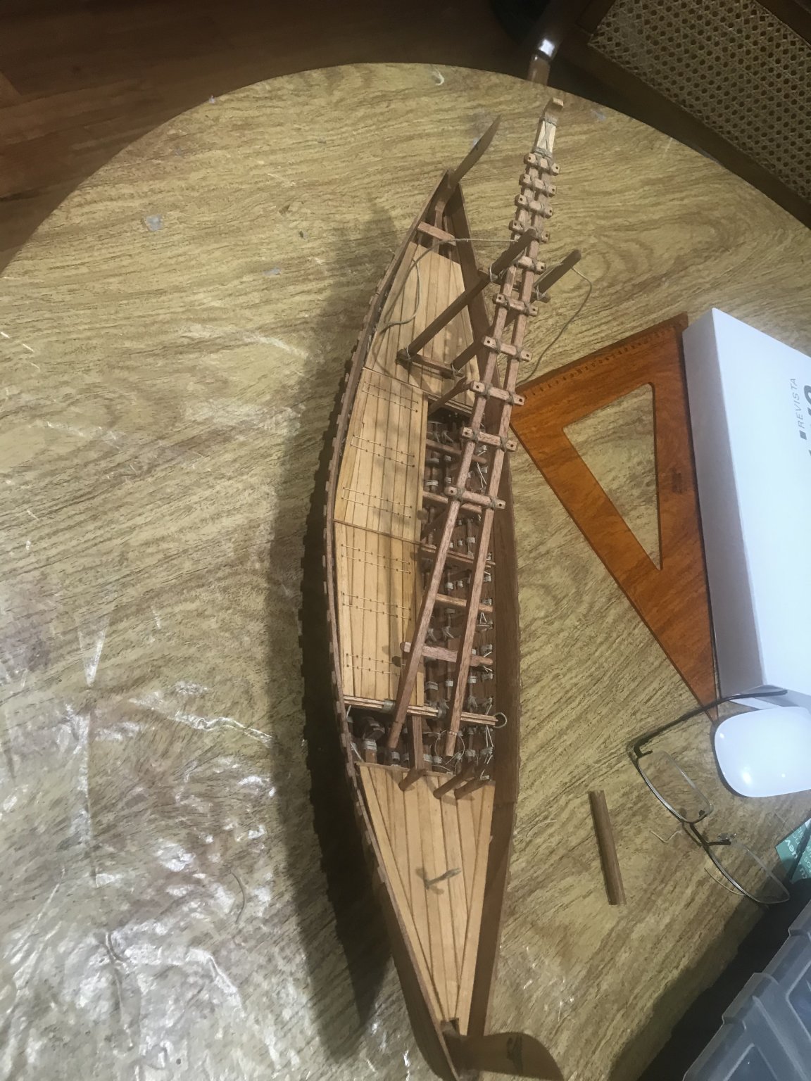
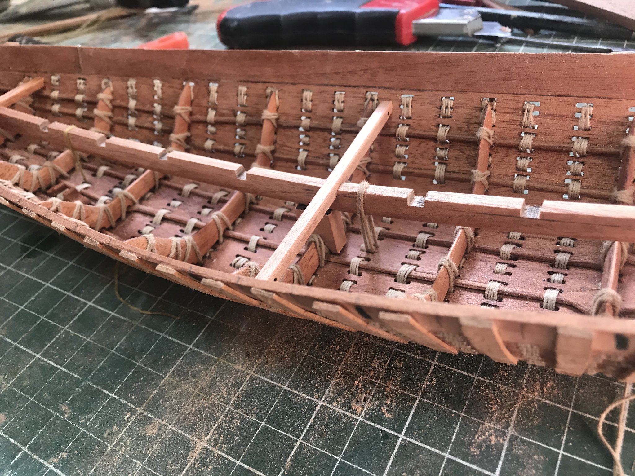
Let’s keep going....
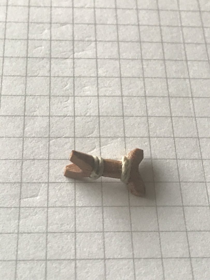
The little “columns” that fix the girder to the hull through the frames are in place.....
The poles for the hugging-truss and mast raising system are in place...
I started to fix the beams to the hull...... they are supported by the girder and tied to the hull....

We are going to install first these beams.....they are the “end” of each deck section....
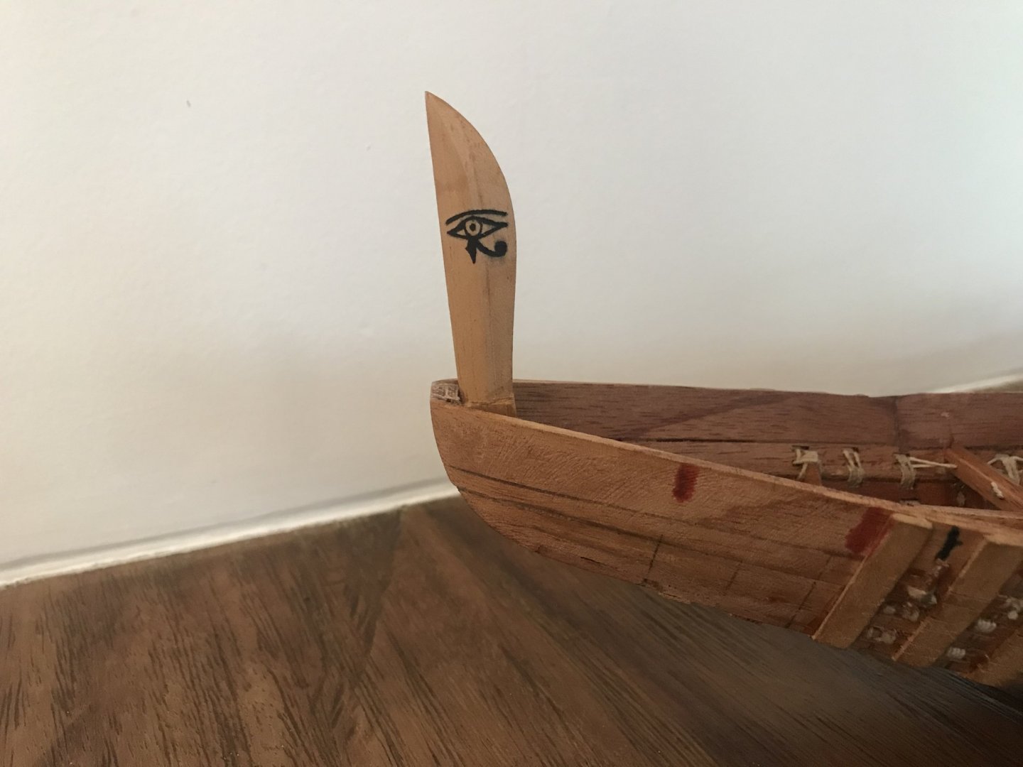
Same thing with the bow pole with the “eye of Horus” ........
- tarbrush, Louie da fly, Brinkman and 9 others
-
12
-
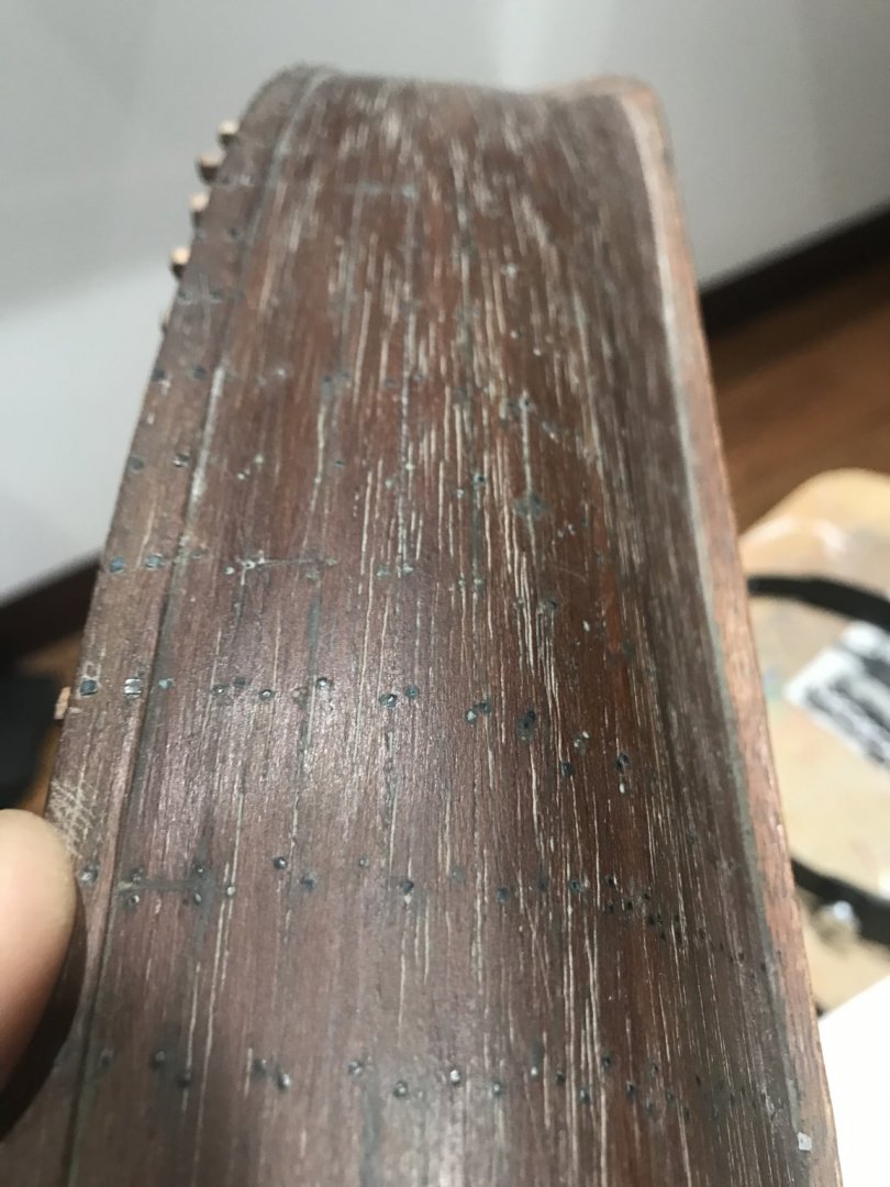
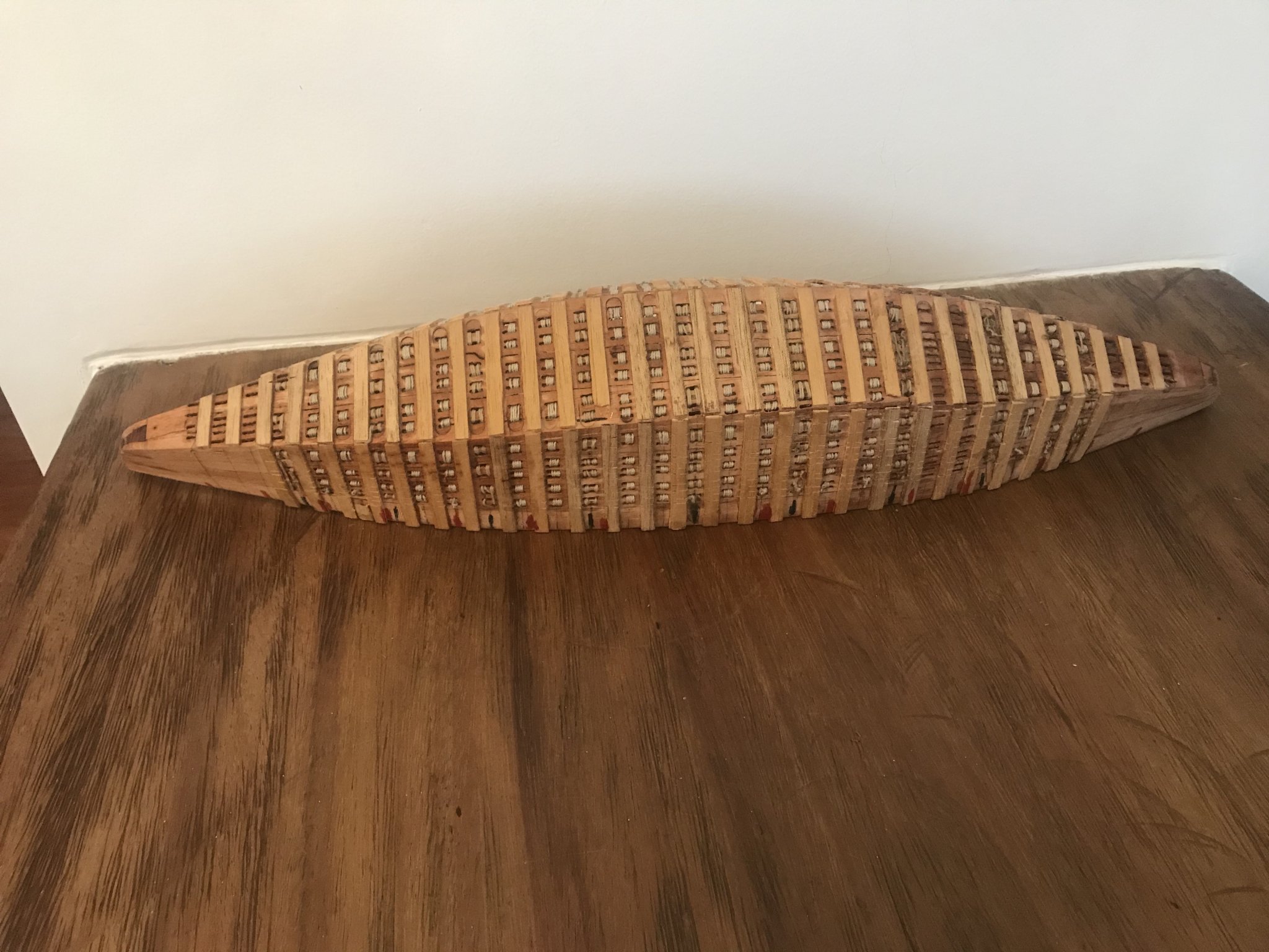
In the real life the planks had some “V” channels internally. They were so thick ......

there were no doble planking. This is only for “model construction “ purposes, since the scale is not allowing to make those “v” channels.....
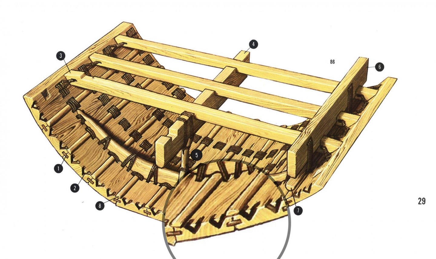
in other books they mention that they put papyrus and animal grease in the joints
-
-
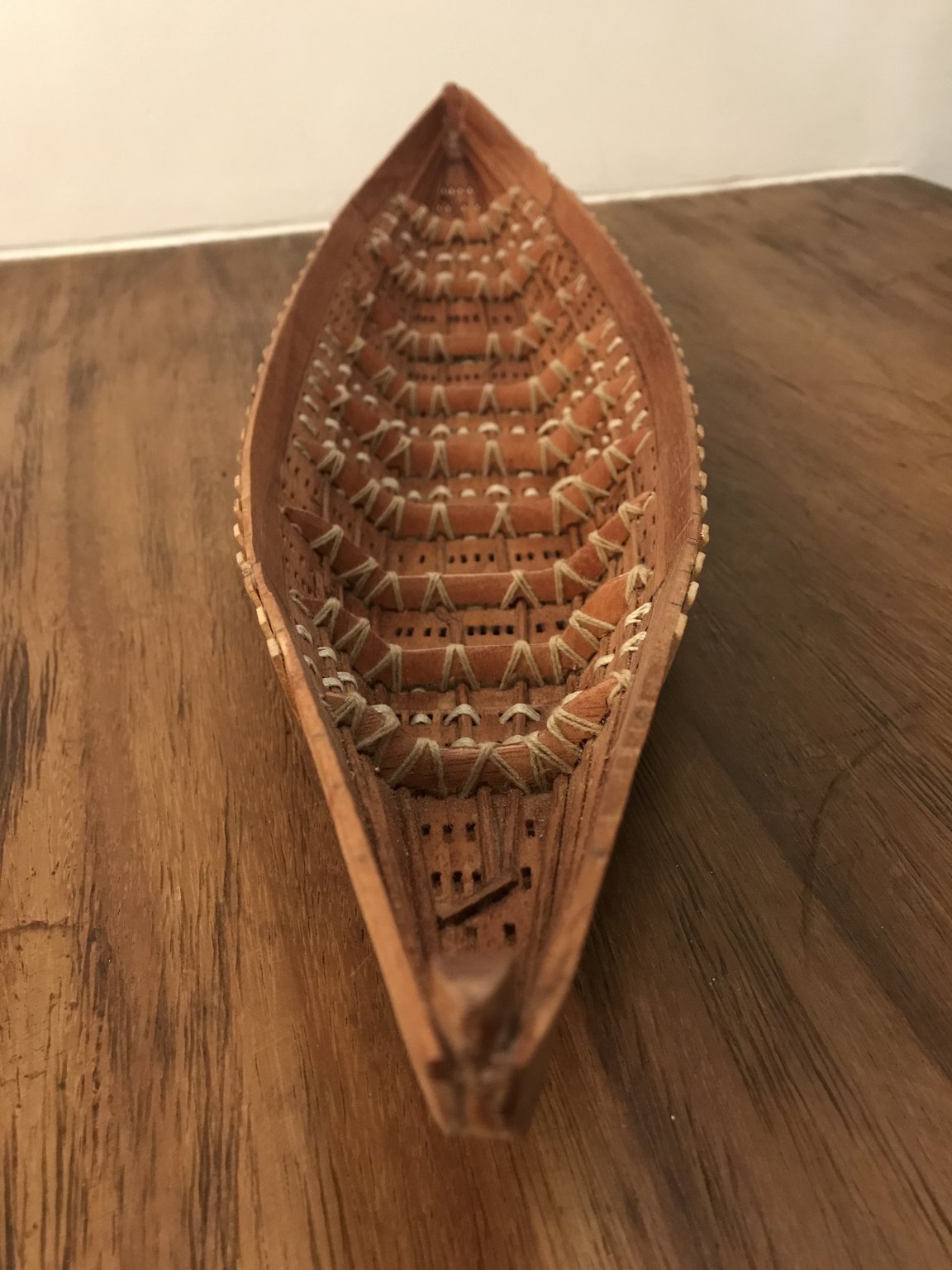
I want to give an update......
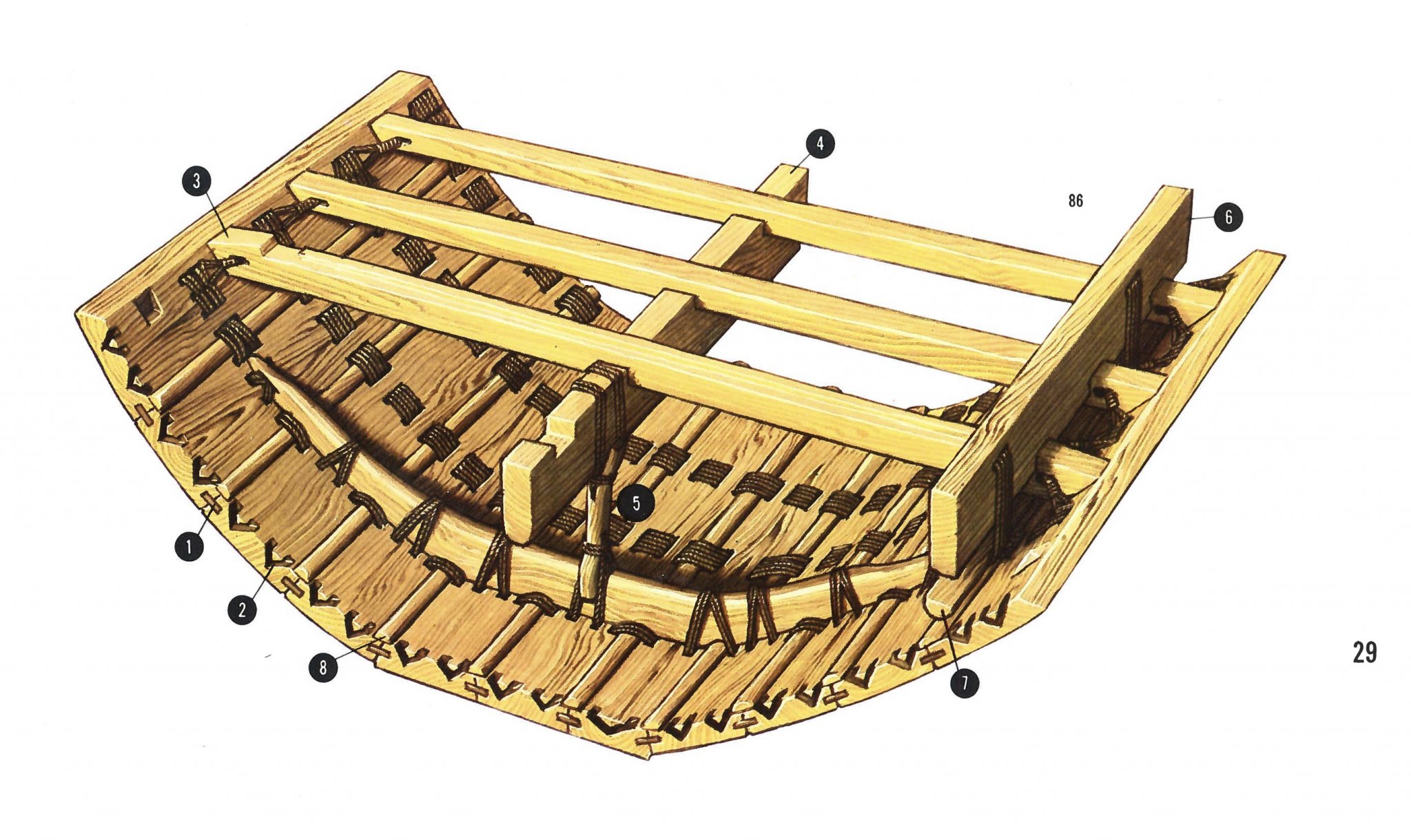
Let’s keep in mind this “famous” picture....
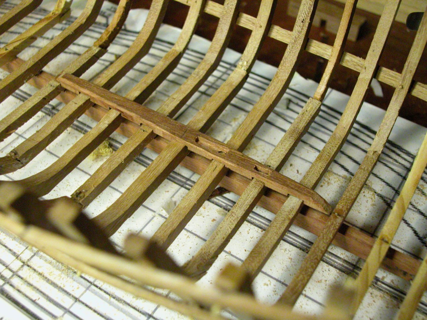
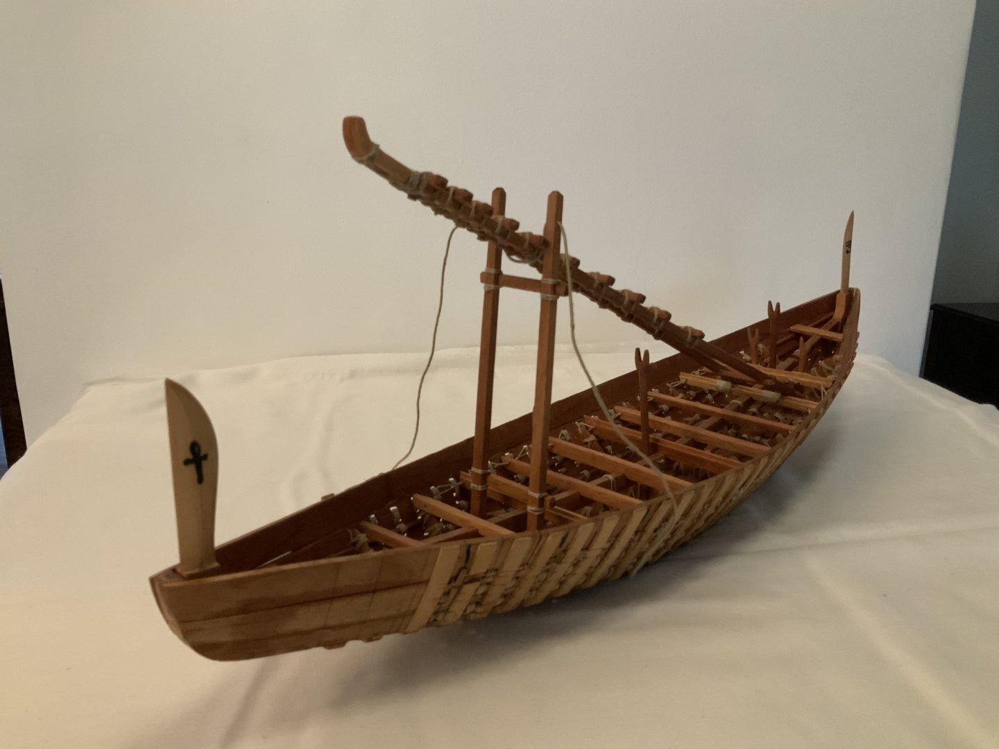
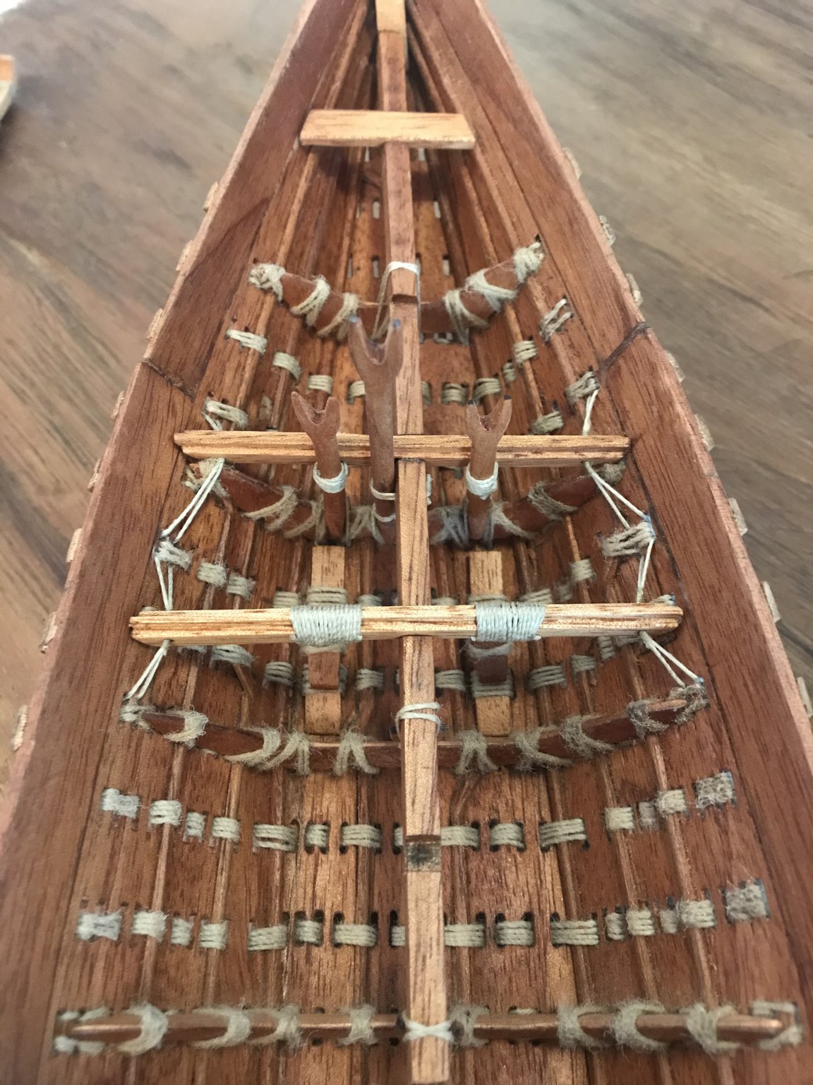
It is time to start with the central beam or girder .... according with the investigation this is the equivalent to the keel. It is its predecessor..... it was among the Hugging-Truss, the elements that kept the hull with this form and gave to it the strength.....
In this case, the beam was convex and in order to give it the right form I needed to tie it up to the hull. Thanks to God I had a lot of holes to do it.... 😀
I did it before the deck beams. It gave me the “exact” position for them.....

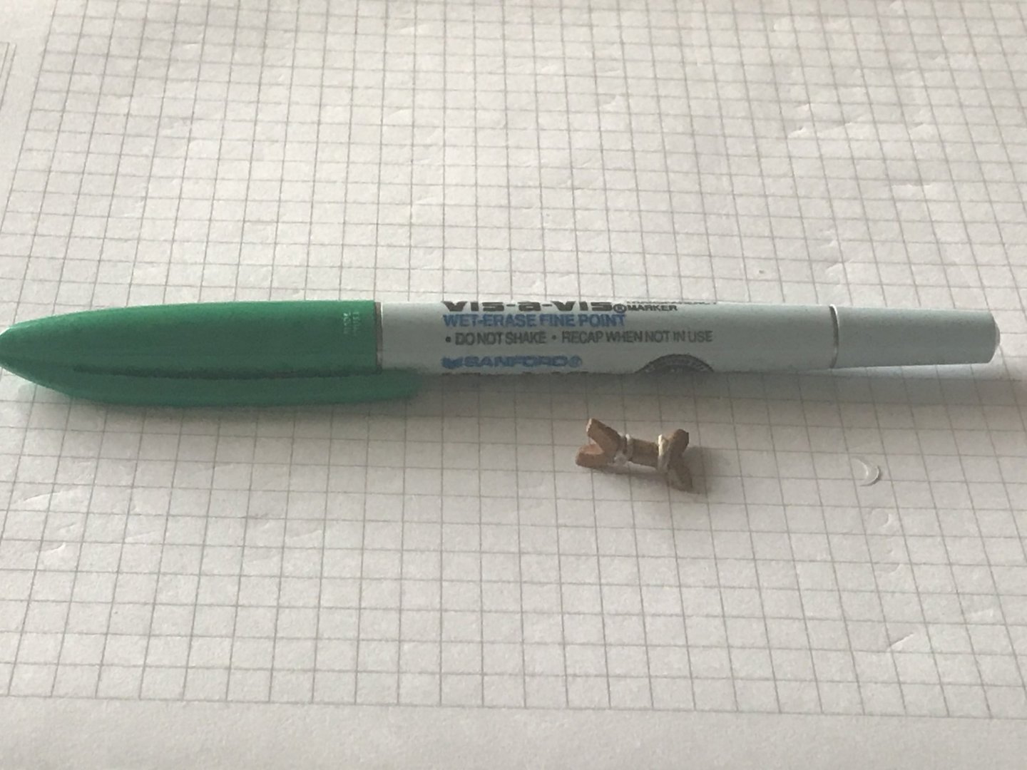
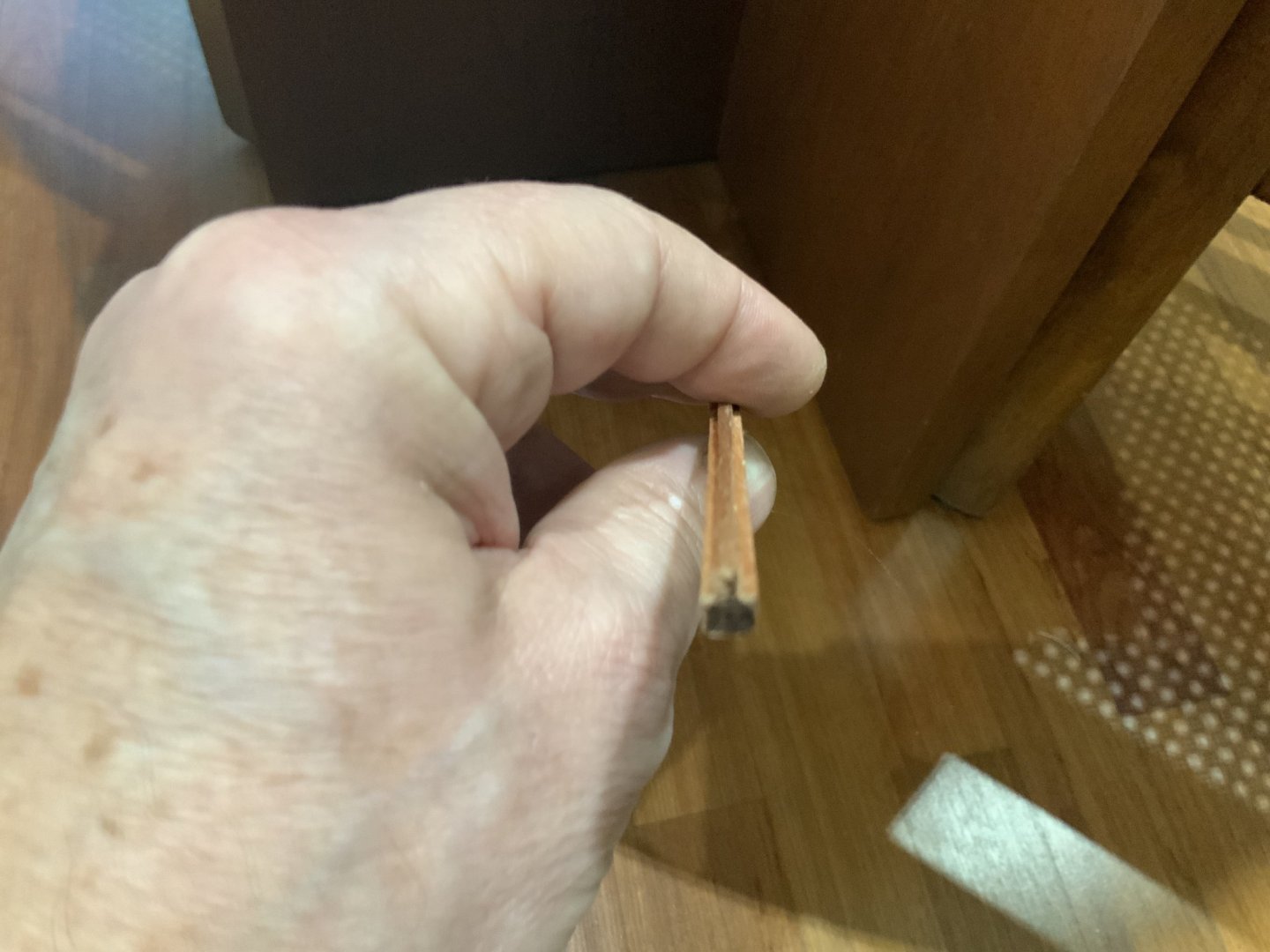
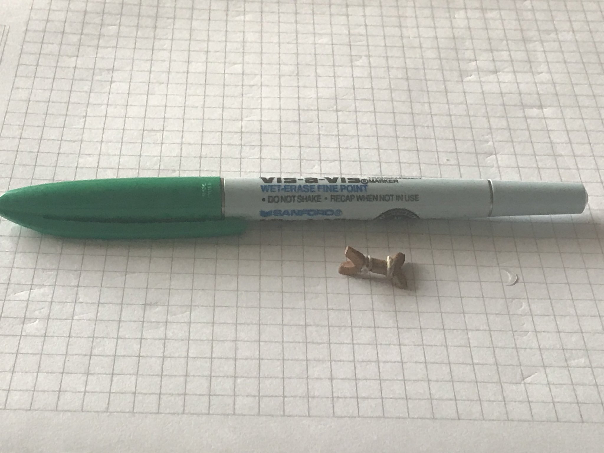
They have a little holes in both ends, that is the way they wil be tied to the hull.....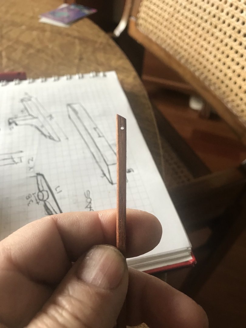
Also the Bow-Stern “poles are made..... I choose different wood in order to “kill” a little bit the monotony.....

- mtaylor, BLACK VIKING, Jeronimo and 7 others
-
10
-
1 hour ago, Cobalt kb said:
Fascinating build. One of the most interesting I have seen in a long time as I have always had a fascination with ancient ships. Will follow your efforts. As a side note, many years ago I lived in Bogota , Colombia and visited Medellin many times. Beautiful city. Saludos
Any way you are more than welcome to come back!!!!!
-
-
-
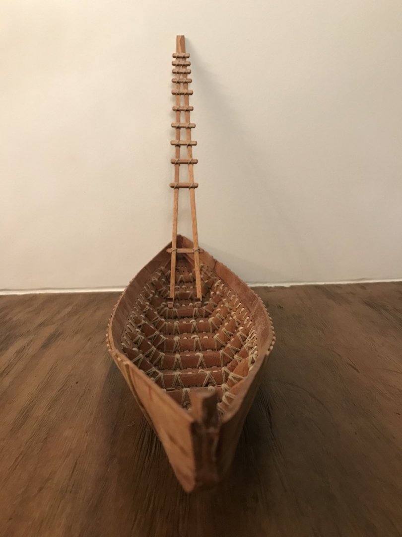
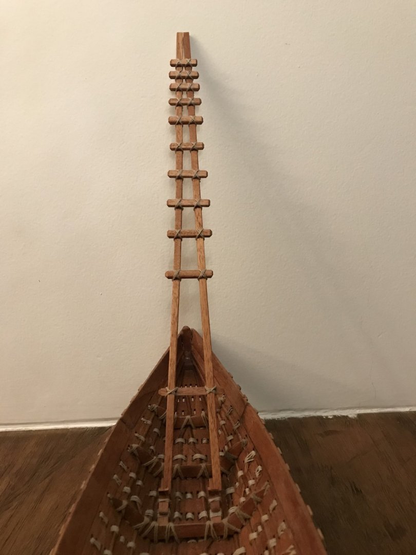
Let’s continue with our project.....
To finish the sewed process in the hull, we need to fix the “skates” that will receive the mast......
And.... the mast....
- tarbrush, oneslim, GrandpaPhil and 10 others
-
13
-
-
Good Job and really well illustrated. I’ll follow from now
for iron nails you can use sewing pins and blued Let me show you a picture
- Louie da fly, mtaylor, GrandpaPhil and 1 other
-
4
-
-
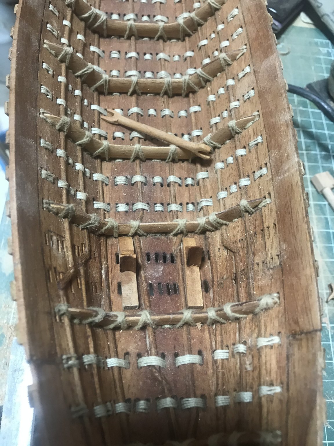
23 hours ago, Louie da fly said:
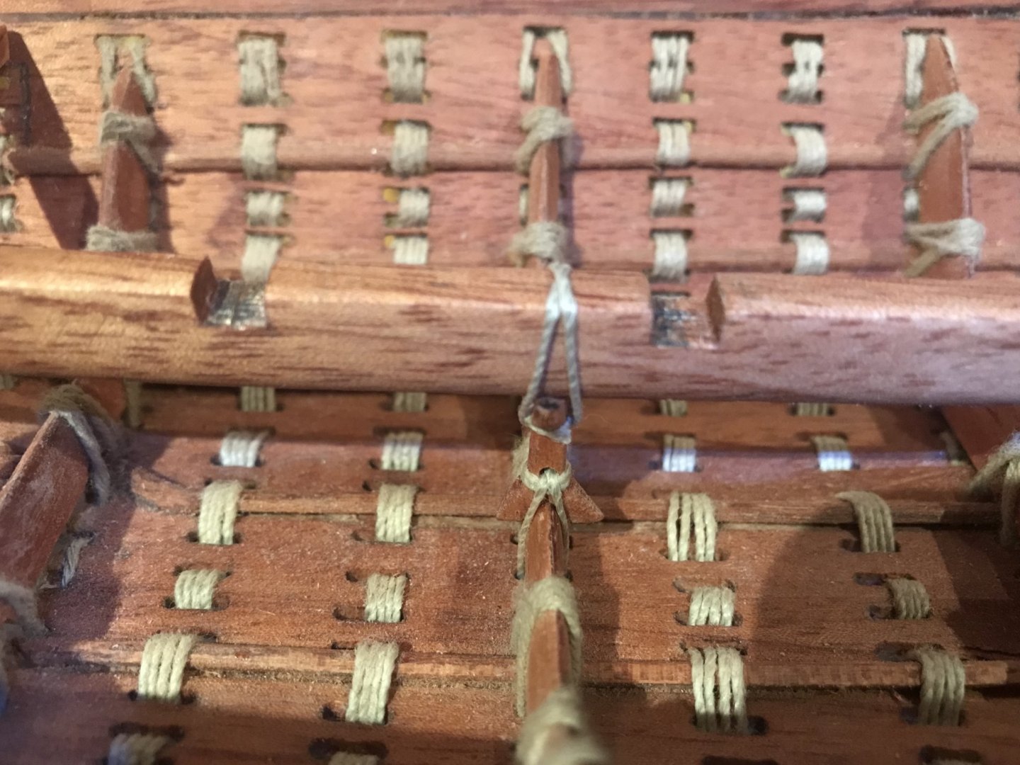
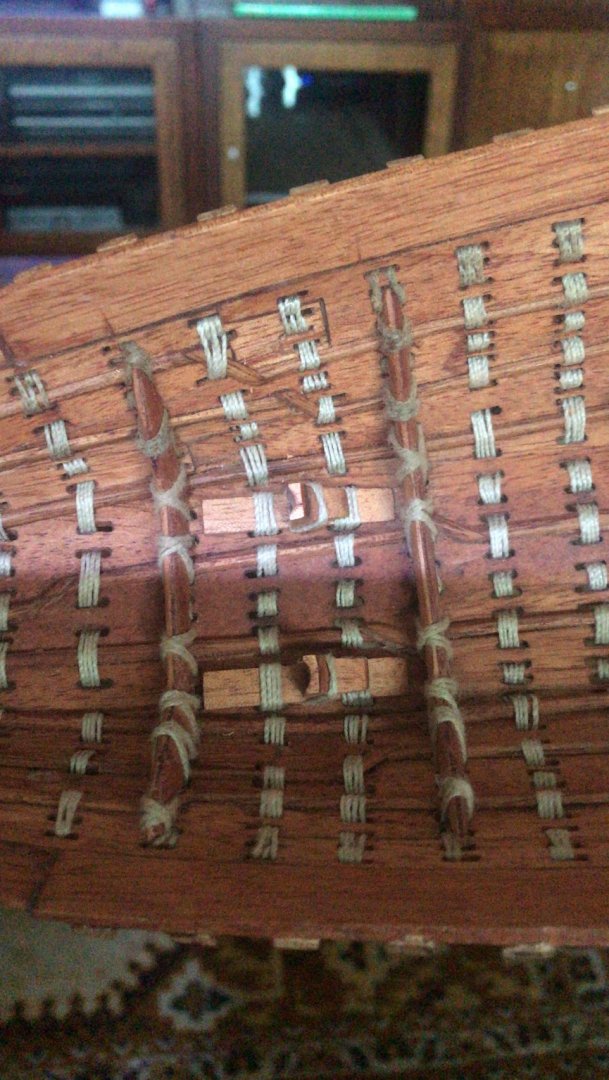
It took me some time to figure out what you'd done - so rather than an incredibly complicated single-planked system with hidden joints and ropes passing halfway into the planks and out again - what in shoemaking is called a "tunnel" stitch
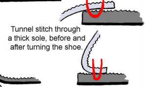
you got really clever and simplified the process, splitting the "solid" planks into two layers each half the thickness, so you have a much simpler sewing job through the inner layer, and cover it with an outer layer of planks with no sewing needed. I take my hat off to you, sir. That's totally brilliant!
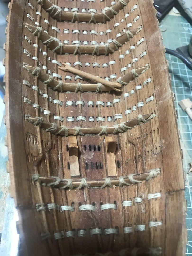
Let’s see the backside of the hull.....

there we can see the idea I was trying to explain
- KeithAug, mtaylor, GrandpaPhil and 6 others
-
9
-
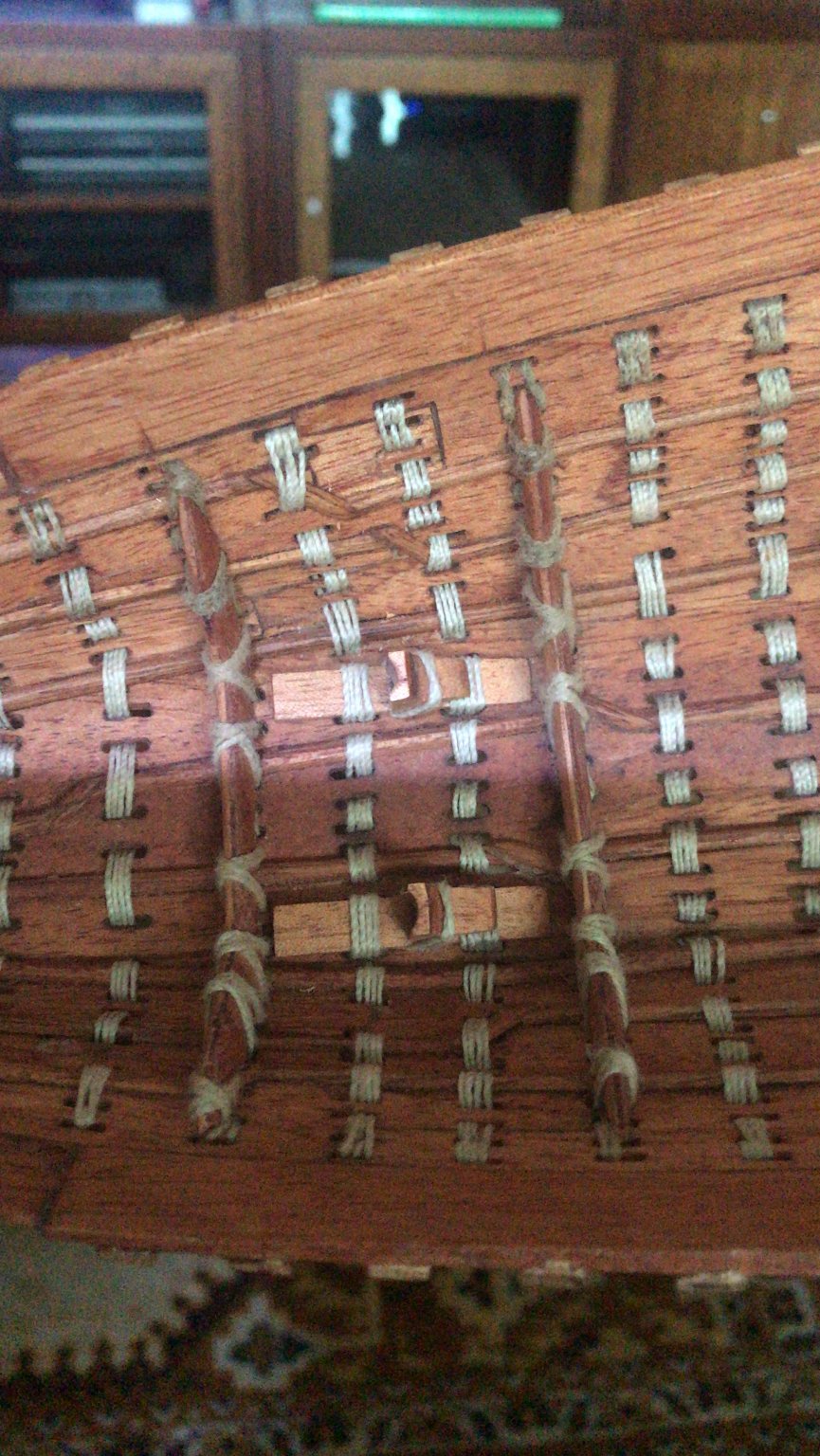
Really It was not just my idea. Vladimir Herrero made de Cheops barge some years ago. He had the same idea. I just took it and improved a little .....
build first the inner hull
finally no channels. I put some reinforcements that made two functions.... reinforce and “channel”
thanks a lot for your kind words
-
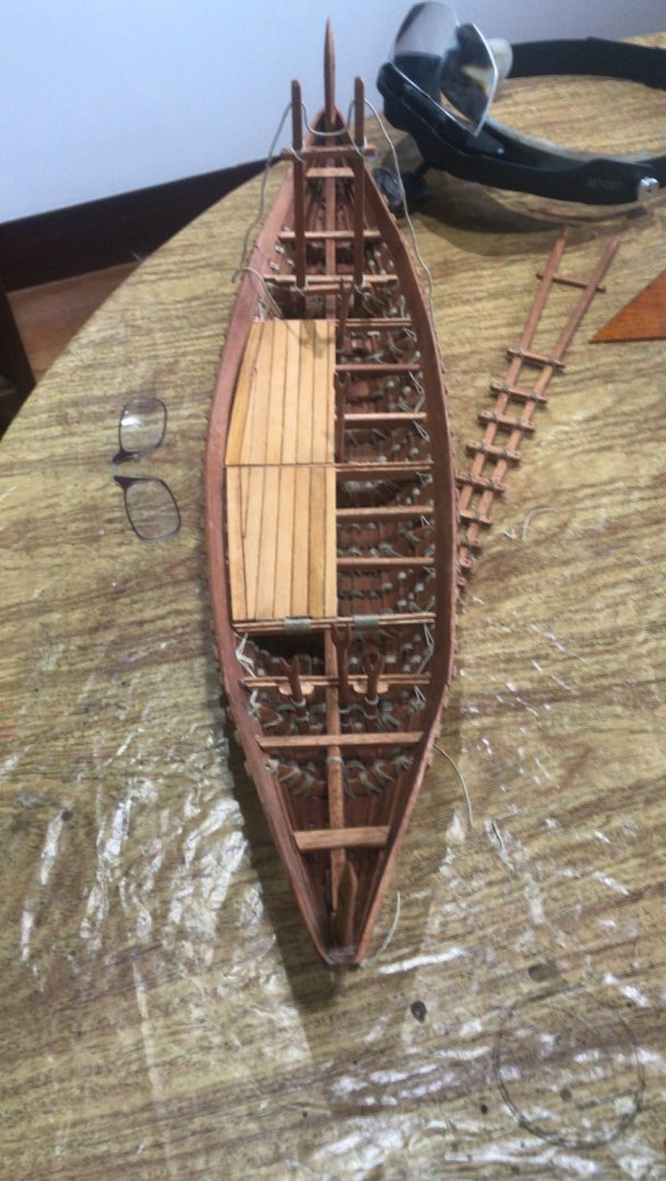
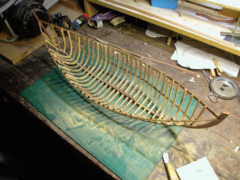
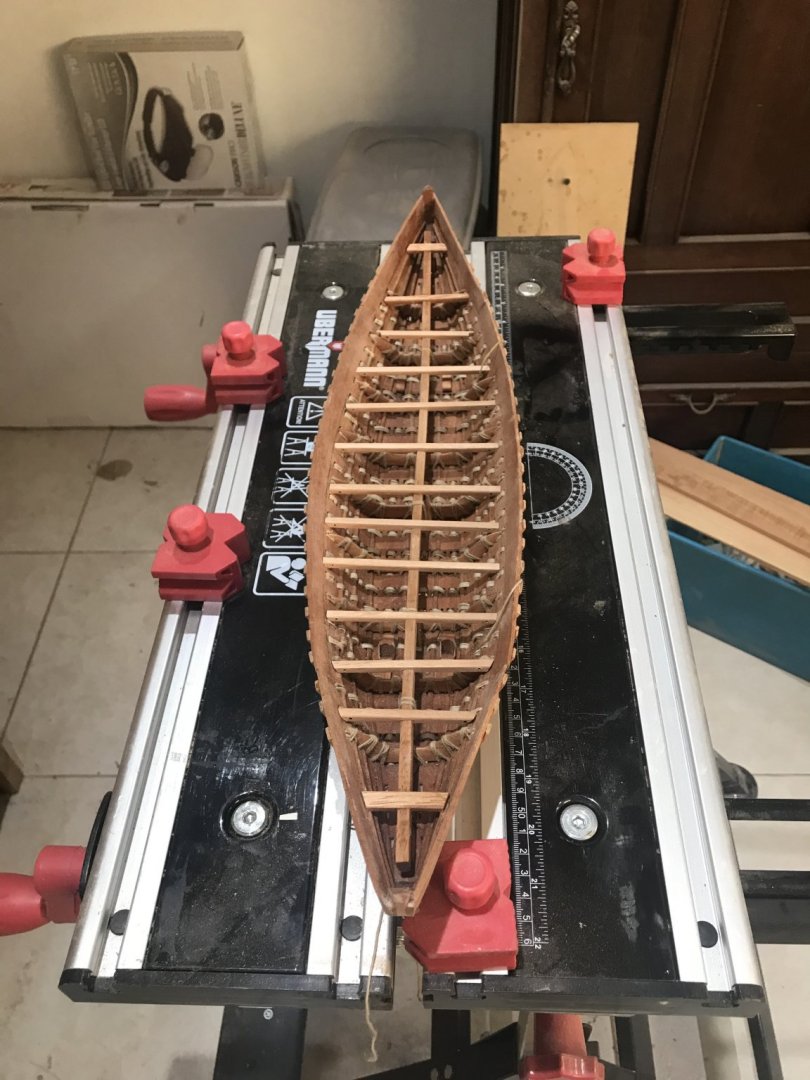
Now.... all the frames in their places........ planks being sewed...


Greek Galliot by Sceatha - 1/64 - Amati plans with modifications
in - Build logs for subjects built 1801 - 1850
Posted
George.....
I'm here to watch......Coming from you this is going to be interesting. Your discipline and intellectual curiosity take me to next level.