Schrader
-
Posts
304 -
Joined
-
Last visited
Content Type
Profiles
Forums
Gallery
Events
Everything posted by Schrader
-
 Thanks for following my log. I have found more literature that is giving me more alternatives. I’ll share it with all of you soon
- 158 replies
-
- 1
-

-
- byblos ship
- Egyptian
- (and 1 more)
-
Six. Three to go and I Was able to take the False frame out.....

- 158 replies
-
- 11
-
-
- byblos ship
- Egyptian
- (and 1 more)
-
What a job!!!!!! And. Dedication. 5 years and counting..... a lot of details for such of scale well done!!!
-
Thanks Bob gathering ideas from my friend Vladimir and George and reading a lot
- 158 replies
-
- 1
-
-
- byblos ship
- Egyptian
- (and 1 more)
-
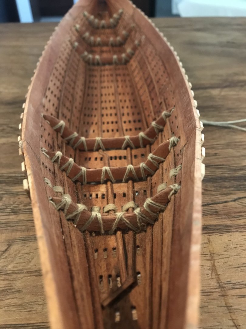
Thanks a lot for all those kind words here........... my first frame!!!!! No glue just sewed.... and.... it worked!!!!


- 158 replies
-
- 10
-
-
- byblos ship
- Egyptian
- (and 1 more)
-
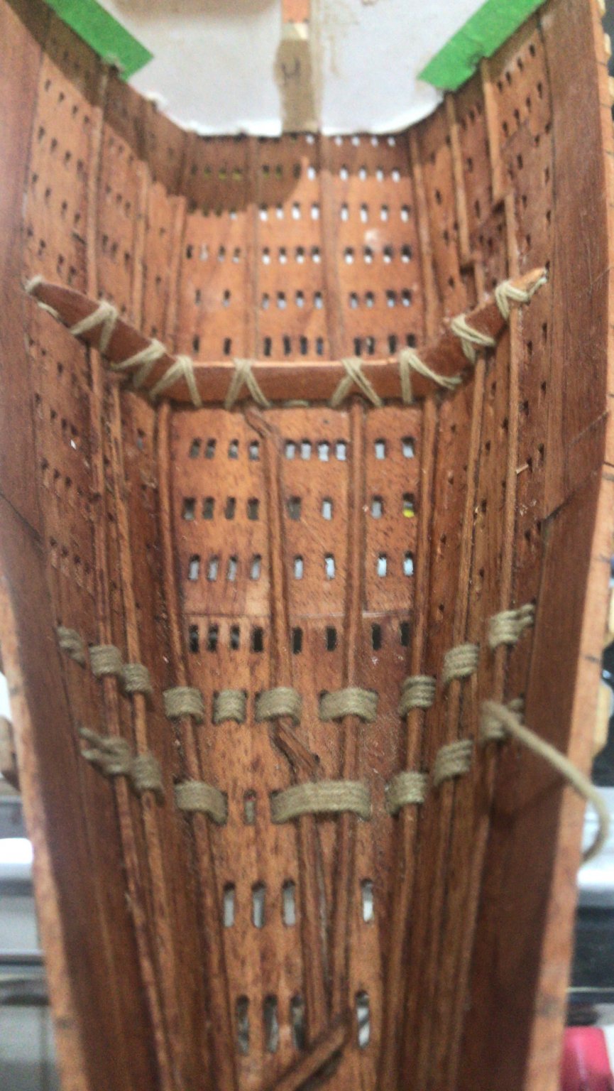
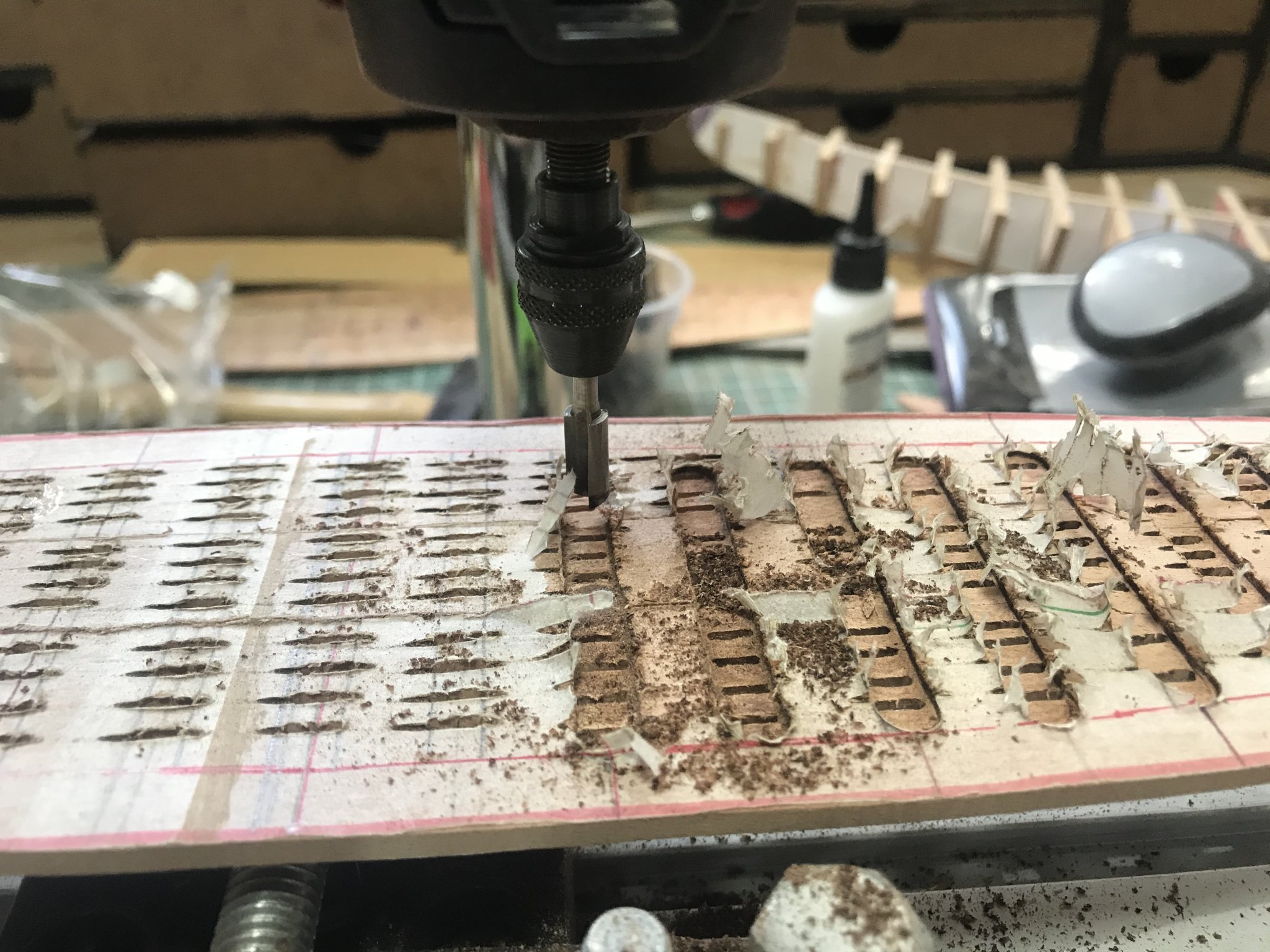
Now I’ll explain how the hull was reinforced..... Instead to make the channels that were made in the bottom, I decided to simulate the same channels with some wood strips......... 😀 Then.... We will cover them with the external planking....
- 158 replies
-
- 7
-
-
- byblos ship
- Egyptian
- (and 1 more)
-
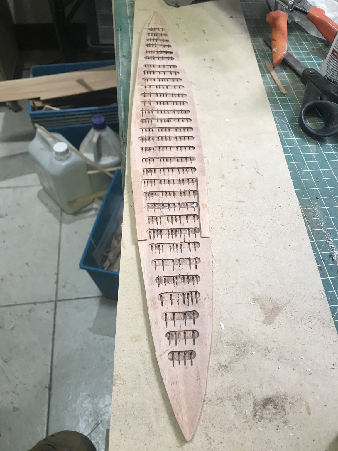
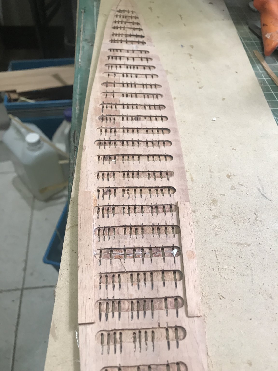
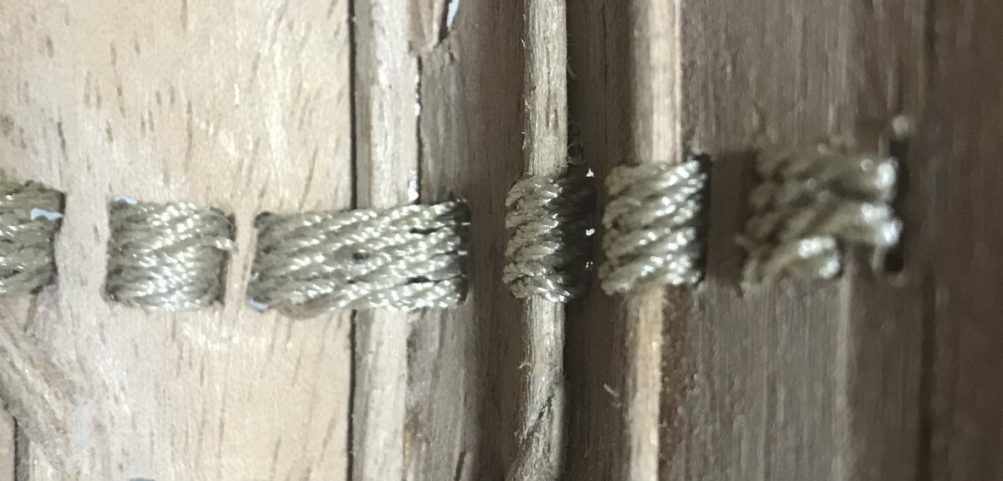
This is simulation how the hull will be sewed..... It looks good........ now more holes....
- 158 replies
-
- 6
-
-
- byblos ship
- Egyptian
- (and 1 more)
-
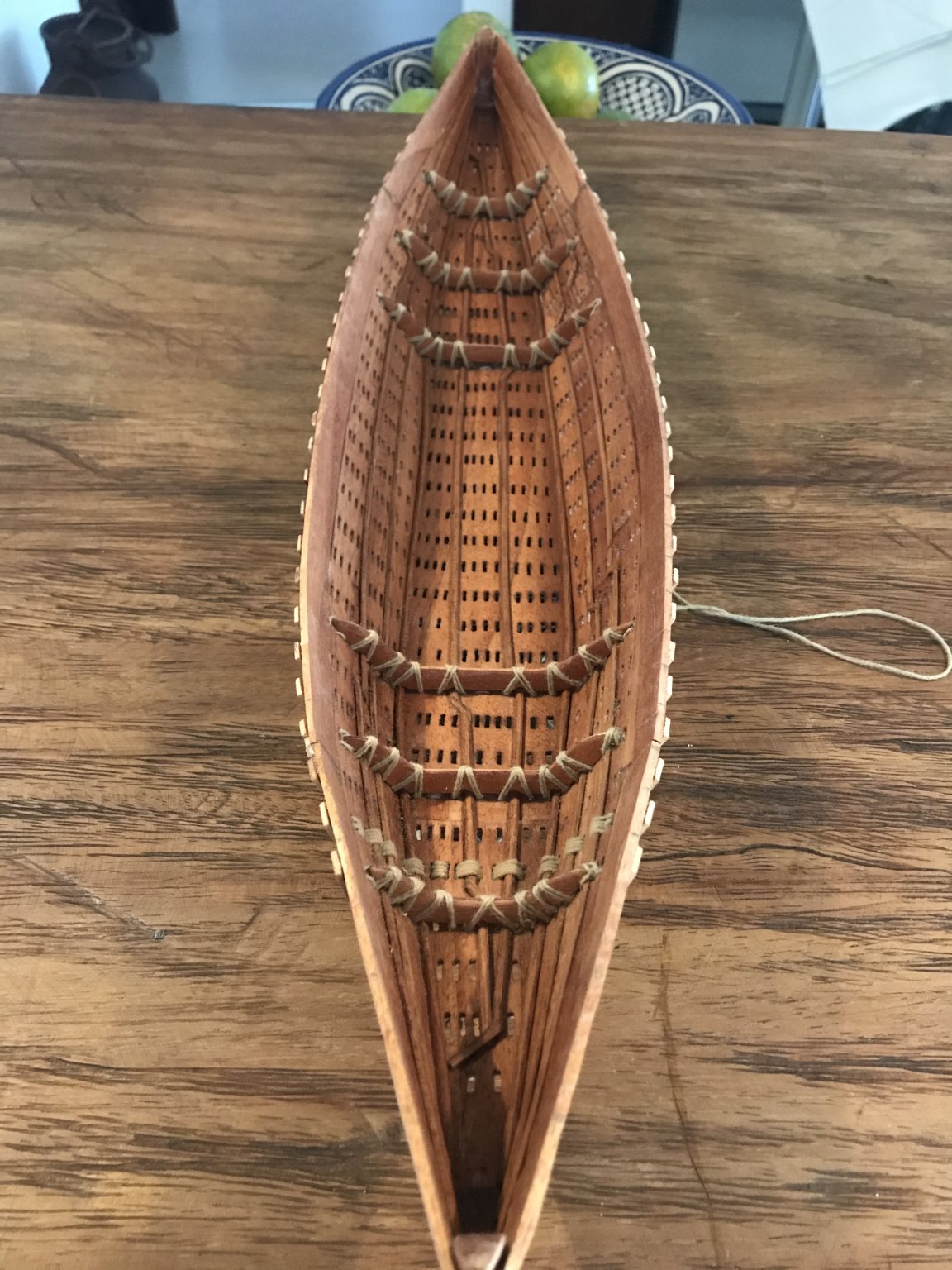
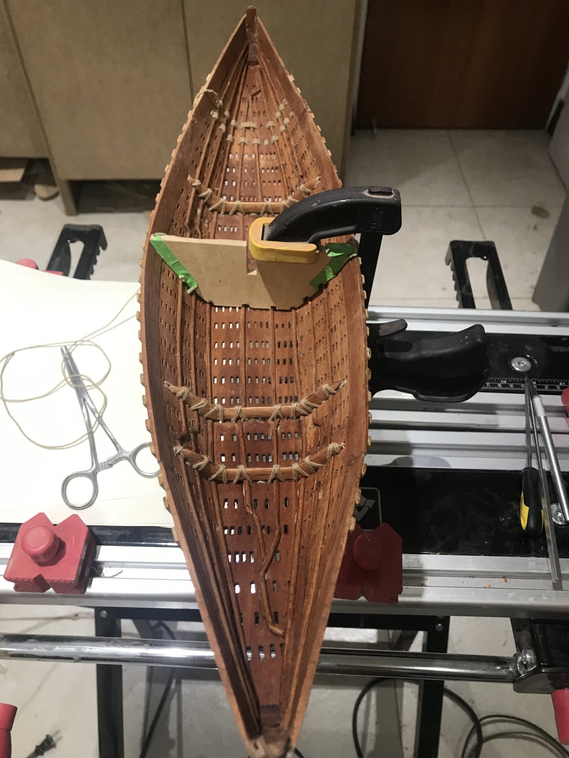
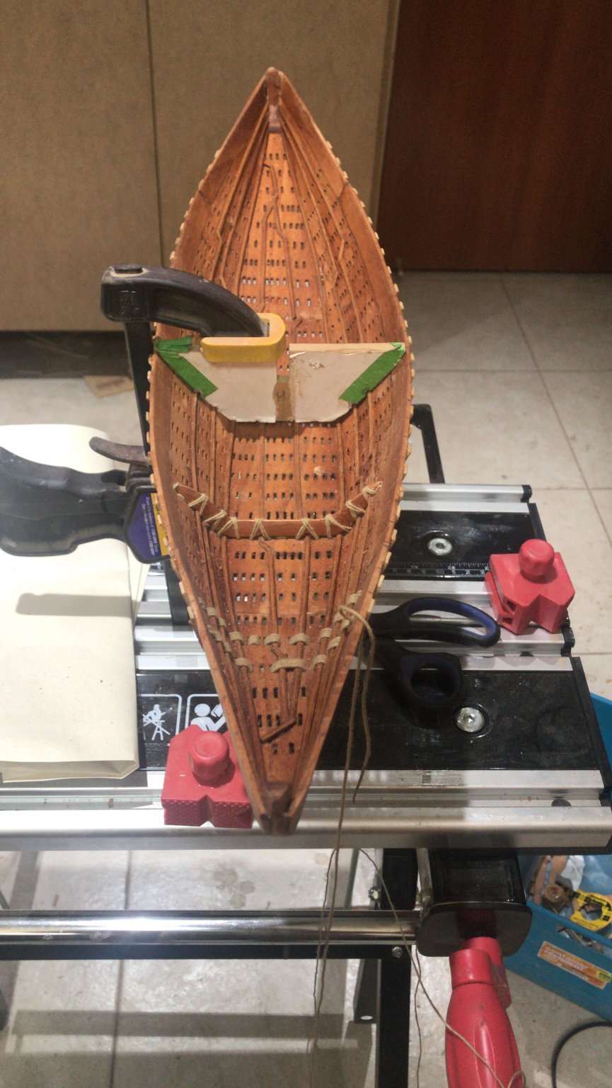
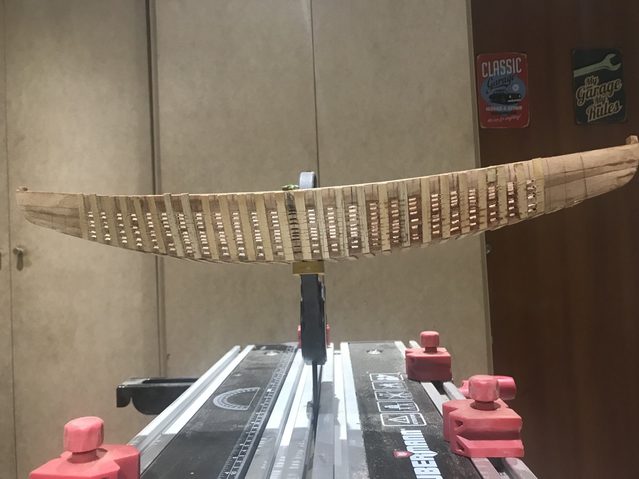
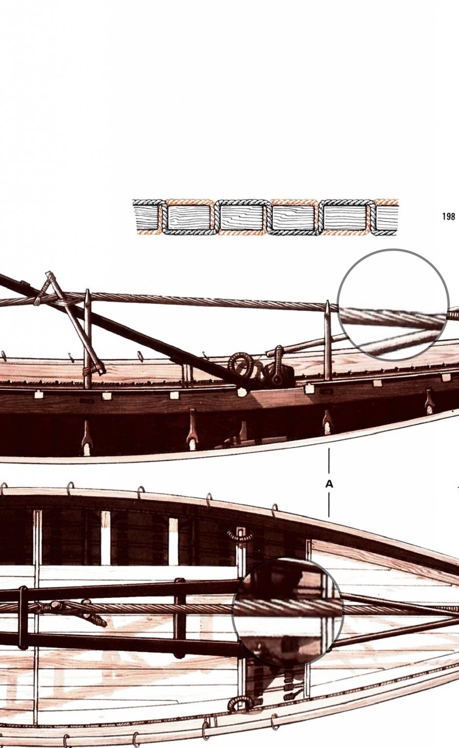
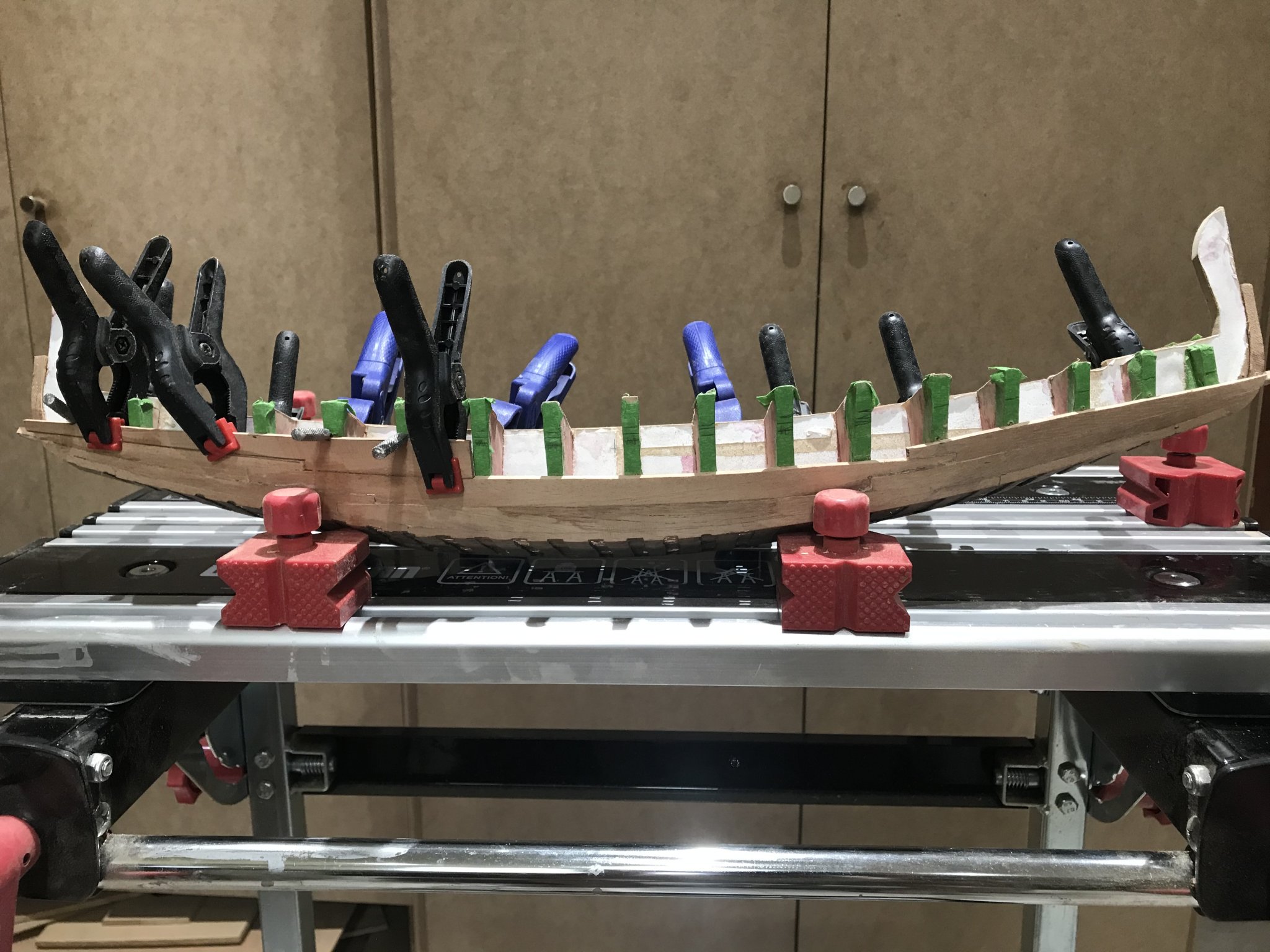
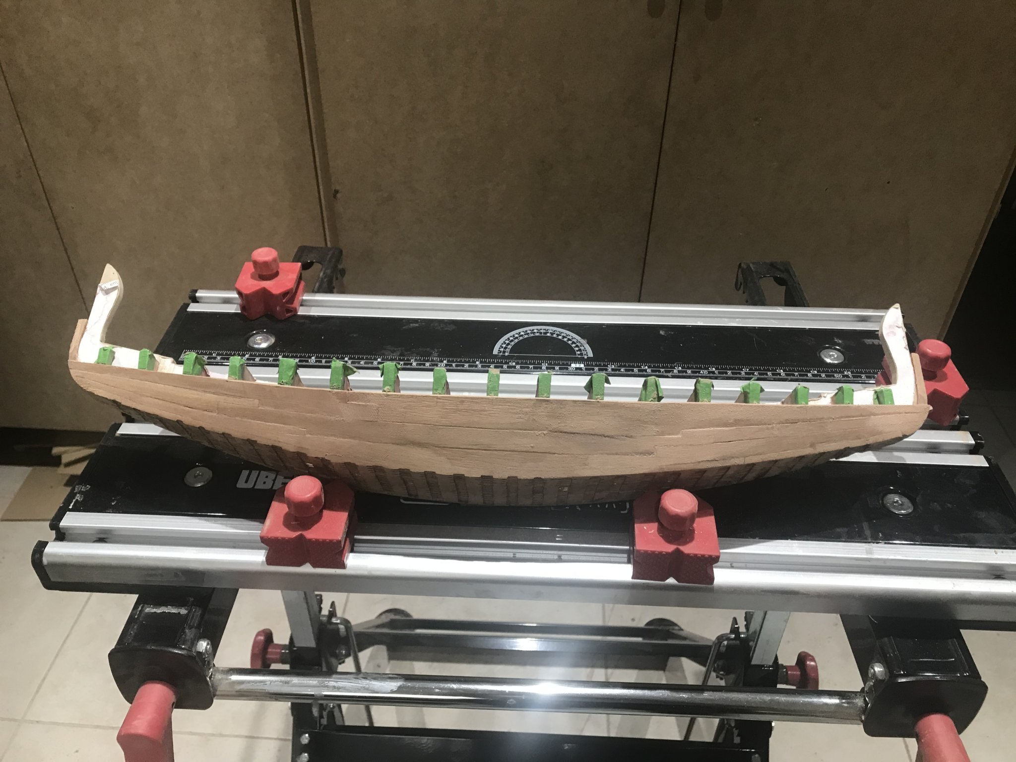
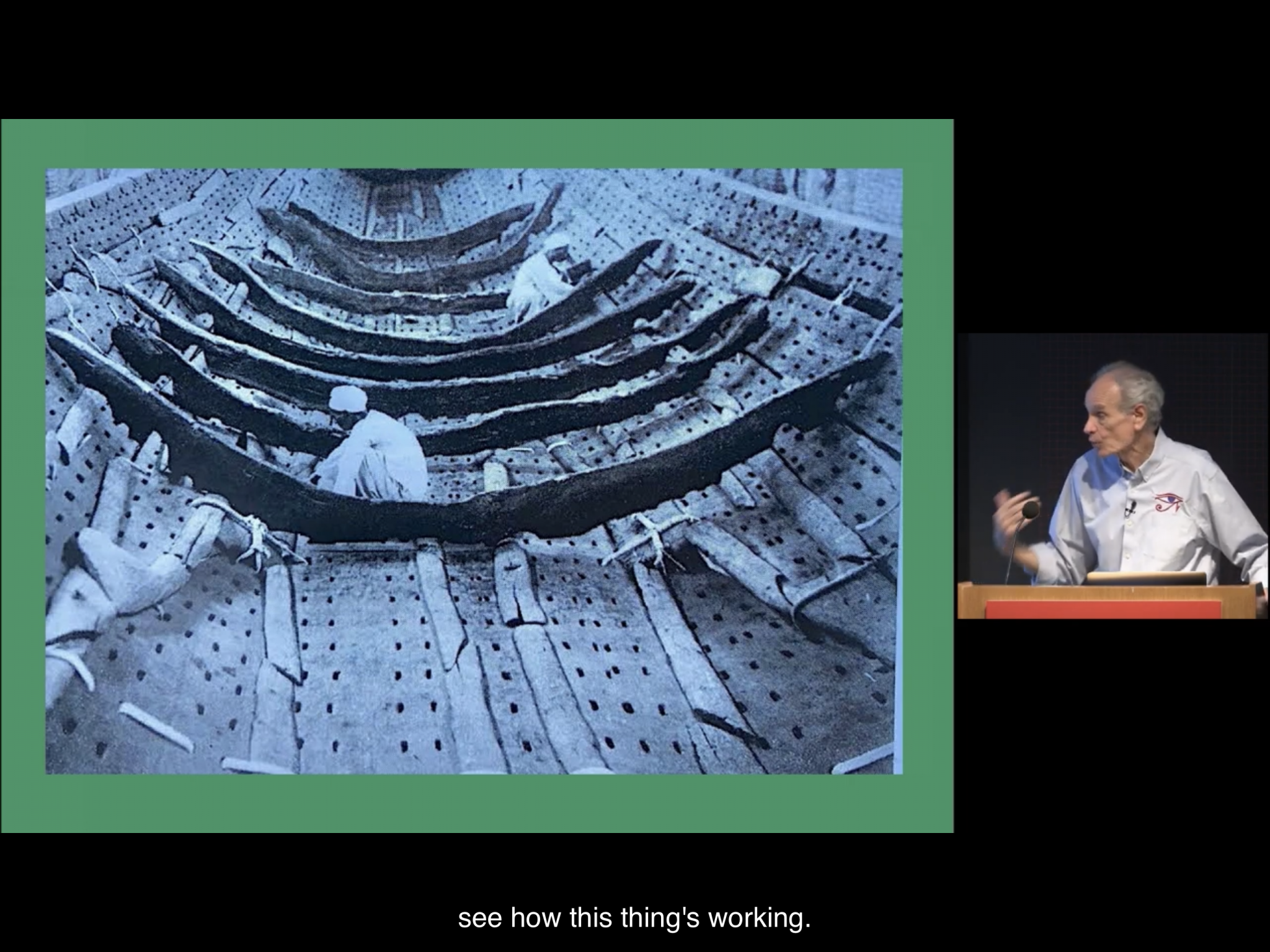
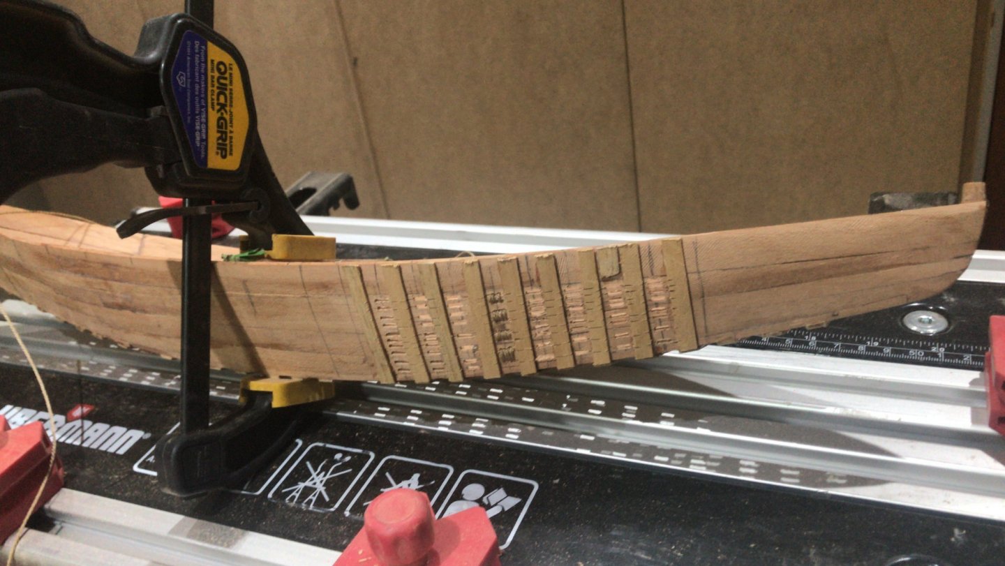
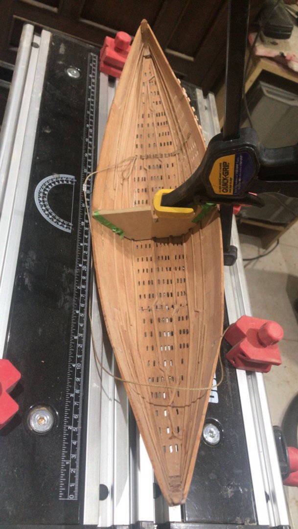
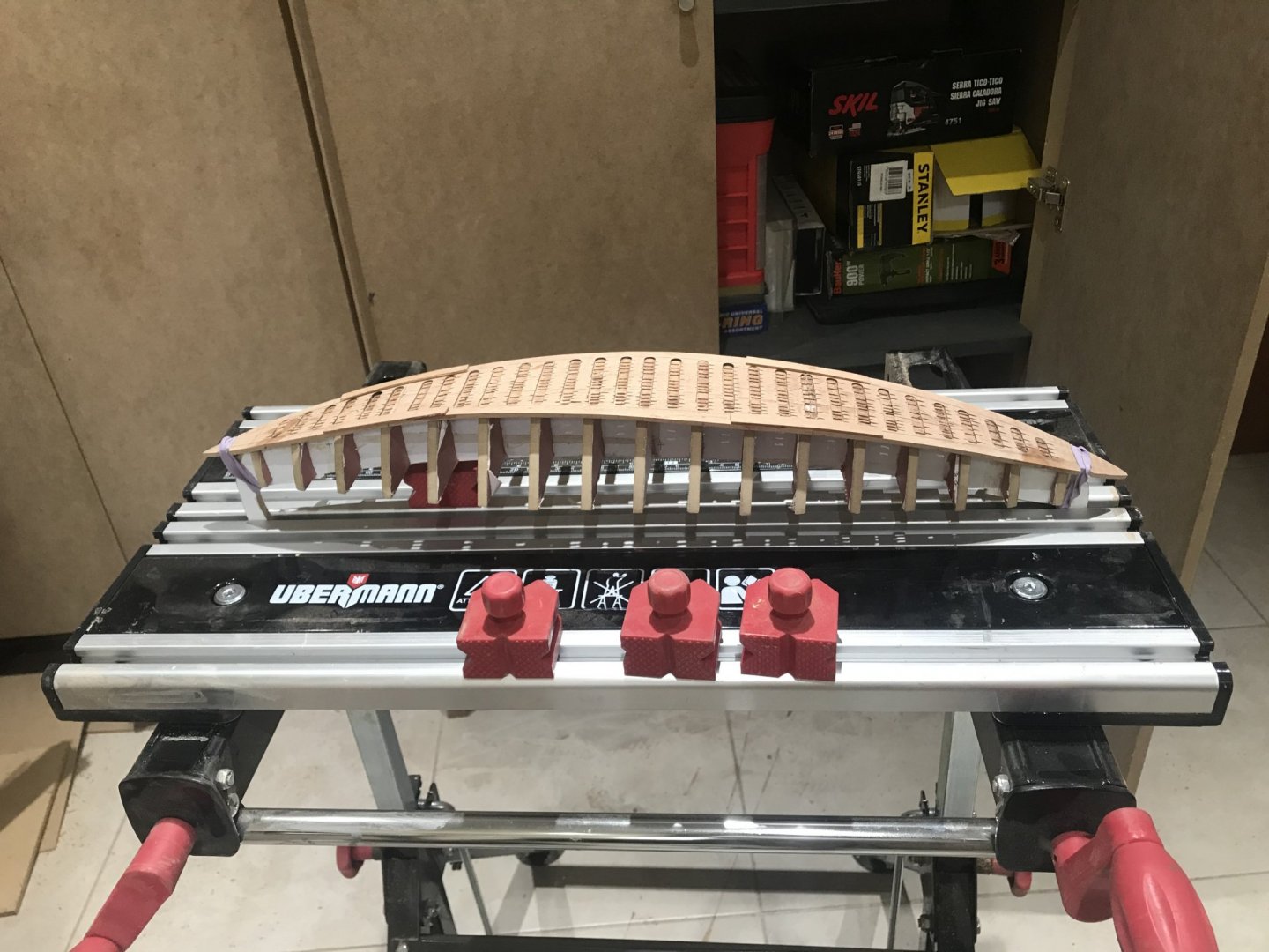
Here I am...... After taking the “mold” out, the result wasn’t the one I expected..... the hull lost its forms and it looked like a “bath tube”😟. So I took my time to analyze how to solve it. In this picture..... In the magnifiers, there is a rope called “HOGGING-TRUSS” and as its name says..... is for keeping the hull bottom curvature. Once it is installed, I guess, I’ll be able to bring the hull to its real form. Also I learned that the frames had their function too.... In the way they are tide to the planks, they should work in the other way around...... ONCE THS HOGGING-TRUSS IS STRESSED, THE FRAMES FUNCTION IS TO KEEP THE FORMS IN THE HULL. TOO MUCH STRES IN THE HOGGING-TRUSS COULD DEFORM THE HULL. In the mid term I decided to use the false frames to keep the hull forms.... This also taught me that the planking needed to be reinforced since to many Stresses in the process..... Next chapter we will see how this little issue was solved......... Let’s remember that these ships had in their planks had tenon joints to keep the planks in site.... Bt in this scale they would be just decorative......


- 158 replies
-
- 6
-
-
- byblos ship
- Egyptian
- (and 1 more)
-
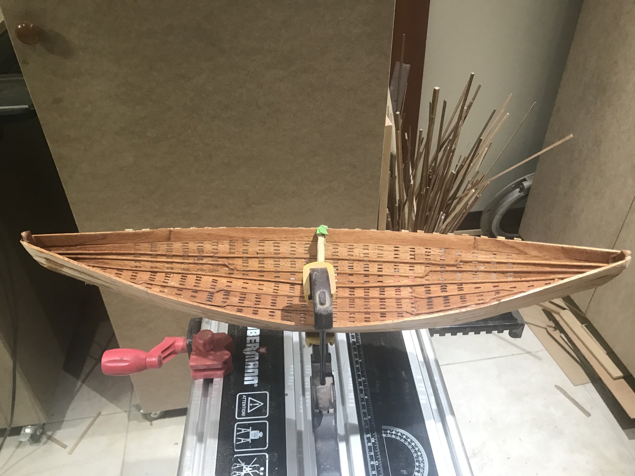
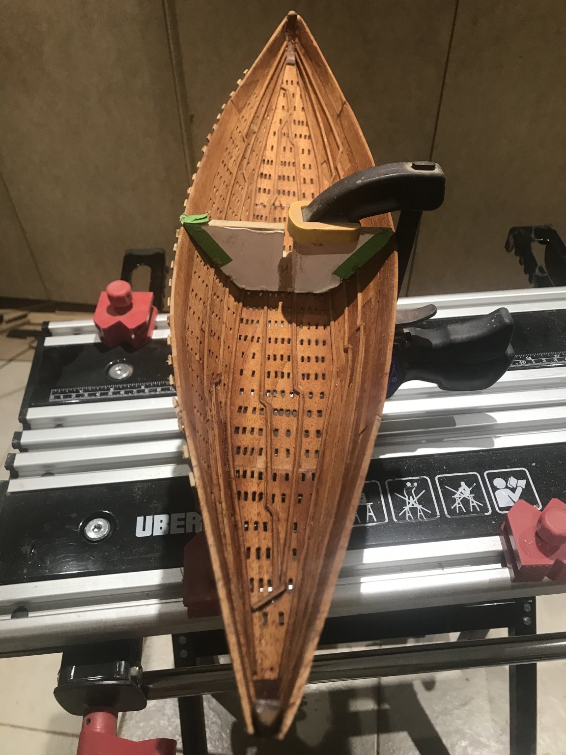
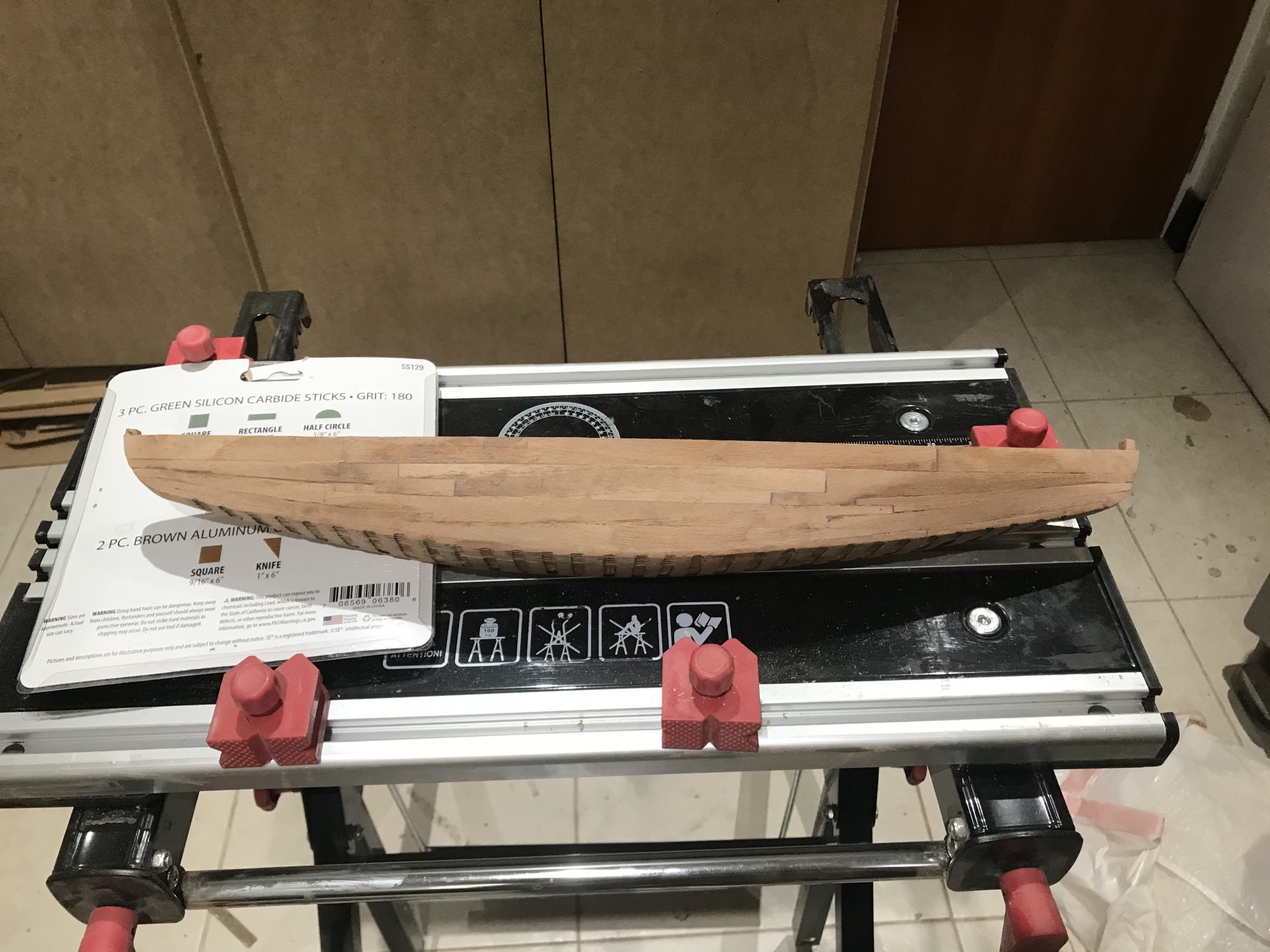
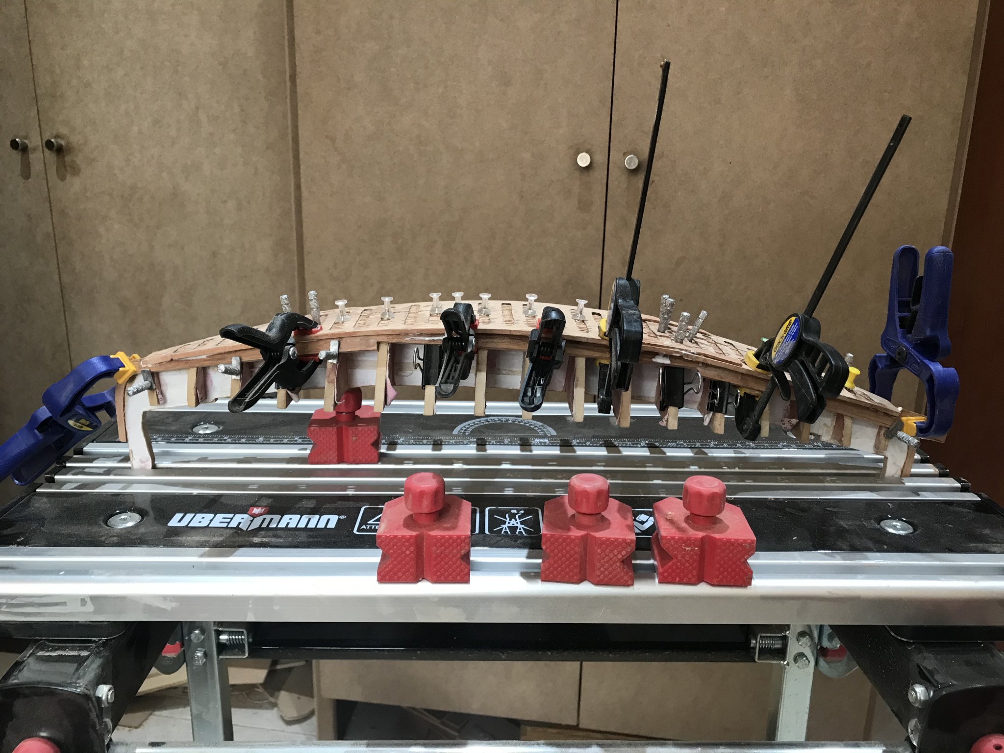
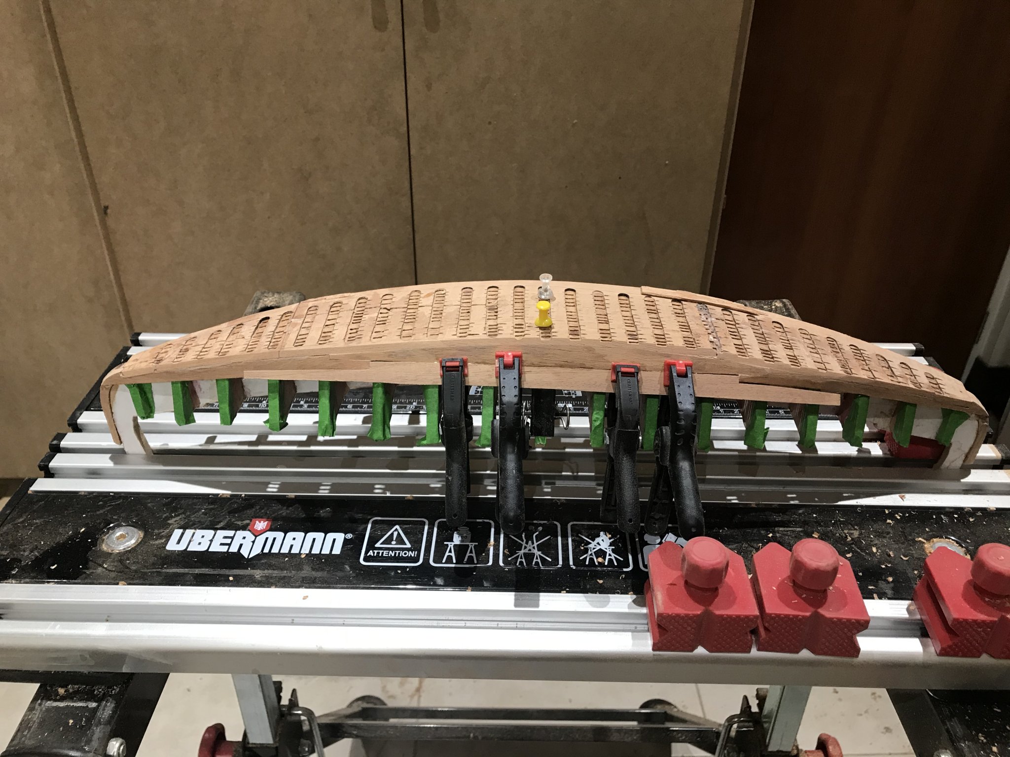
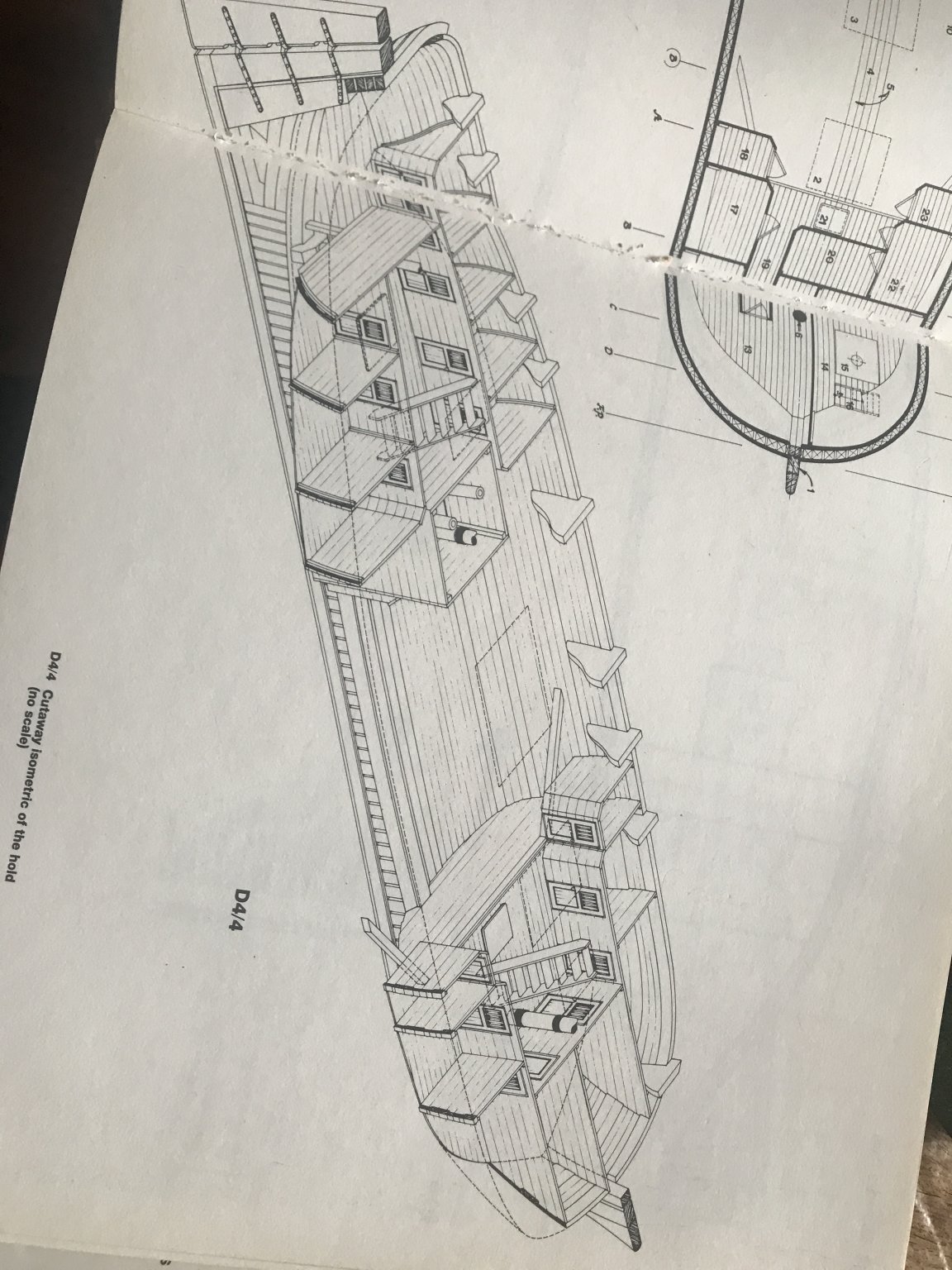
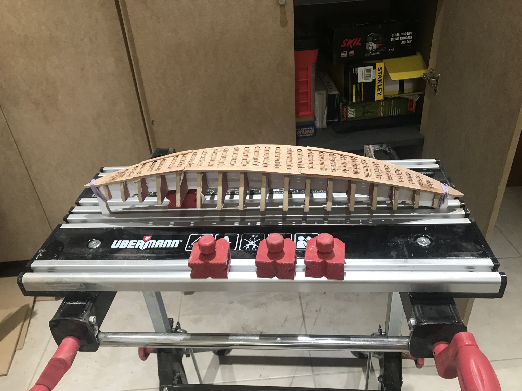
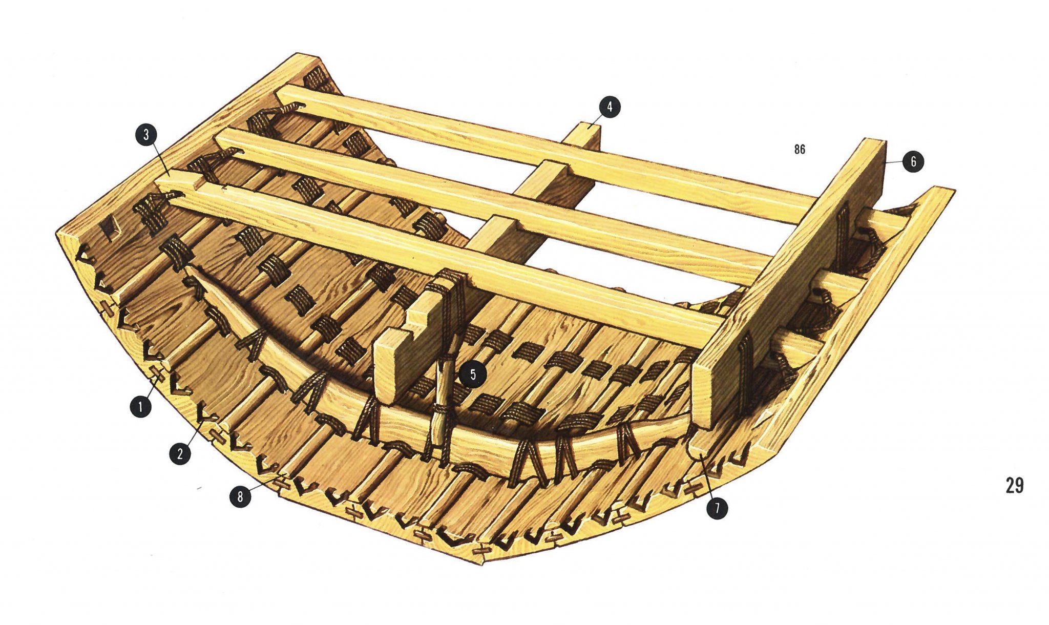
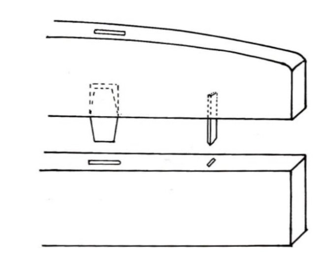
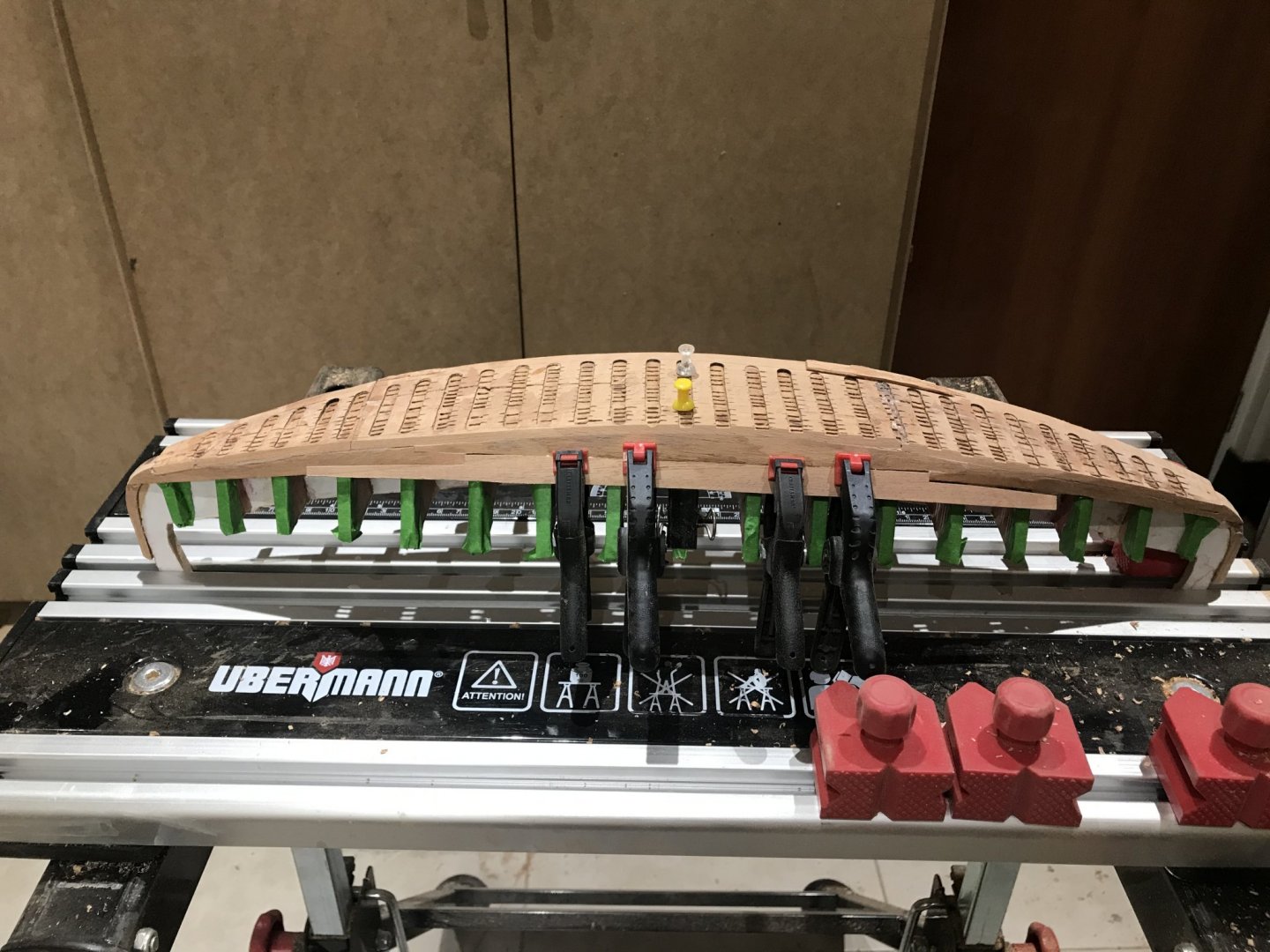
Here I am again..... After doing mu research and many attempts, I realized the the Egyptians were right 😀😀. The sides planking with planks 3.2 mm thick was so tough. So I took the image above and went to “copy” more or less the distribution and..........BINGO!!!!! They fitted.... But before I needed to have somehow, the way I could fixed the planks without attaching them to the mold. Let’s remember that the frames were something that were installed after many tasks so the planks needed to “stay” there by themselves. I built a couple of pieces..... Longer that it was needed and I glued them to the base an to the mold. The idea was to glue the planks to these pieces.... Let’s see..... Geometrically the planks fitted right. Just one “line” to go and it will be finished.......Just exterior sanding. Once the other side is finished we will be able to take the mold out and start to work in the holes and channels. Really was difficult to keep the planks in its place. Wood glue, presses and waits 20-24 hours per plank...🙄


- 158 replies
-
- 9
-
-
- byblos ship
- Egyptian
- (and 1 more)
-
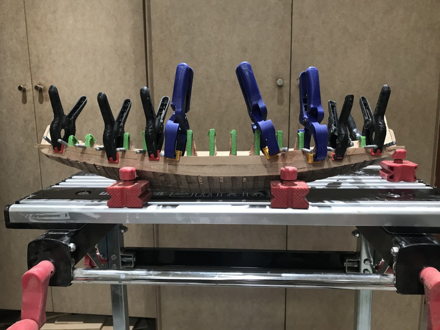
Ive been wondering how my keel could get so twisted, and then i realised i still had the bit of ply that the precut keel came out of. It is twisted and bowed the same way as the keel section is, so its been mishapen since before i started. I know i checked all my frames and made sure they were good for level and i had cut spacers to space them apart whilst glueing it all up, but i dont think i ever payed much attention to straightness, as it was pretty flexy due to length and thinness of the section. The bottom rear and front decks have nothing in between them, so i only started to notice some fitting issues on the full length mid decks, which fitted pretty good at both the back and front, with only some of issues in the inbetween frames. I assumed at the time that my frames maybe werent as good as i thought, or perhaps it was simply issues with the precut ply not being perfect, or maybe a combination of both. If i had payed more attention then, i would have noticed that it was actually due to the twist and bow in the keel that was causing the ply to fit good at either end, but badly in the middle. But as usual... i didnt pay much attention, and proceeded to glue it all up and keep working, with every piece added making it more and more rigid, but out of line. I wasnt really sure how to go about fixing it, as it is quite bad, but then i realised the only item running full length and tieing it all together is the middle deck pieces, which if cut in the middle, would let the keel flex a bit. So i cut it about 6mm left of the line marked. 60 59 It does let the keel flex, but unfortunately the keel has a gradual bow along most of its length with a bigger twist at one end, which cutting the deck cant really help. Ive managed to get it on dry and get everything that goes through the decks aligned to where they should be, and am now glueing it on. Having to do it in maybe 3 sections to help glue it correctly to counter the twist, and i dont have enough clamps to do it all at once. 61 Need to apply a bit of pressure to the deck to get it to take the curve, so i temporarily ran some wood lengthwise below the crossbeams to give the clamps something a bit stronger to clamp on to. 62 Its not going to be perfect, the frames are a bit one sided in the middle of the boat due to the keel, but i figure i will wait till the deck is glue in place and see what works. Either build my frames out on one side and sand them down a bit more on the other, or alter the deck in the same way, take a bit off one side and add on to the other. My recommendation would be to do the planking in the deck first. It is easier to install, cutting borders, and accommodate the planking as you wish.
-
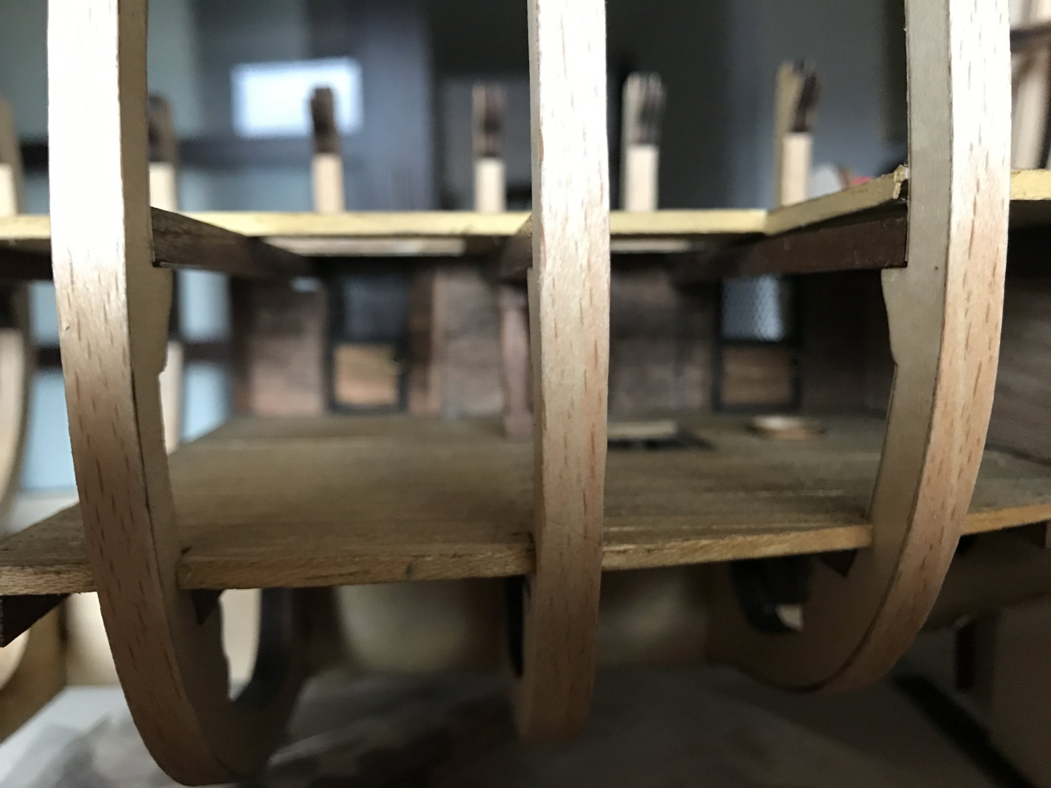
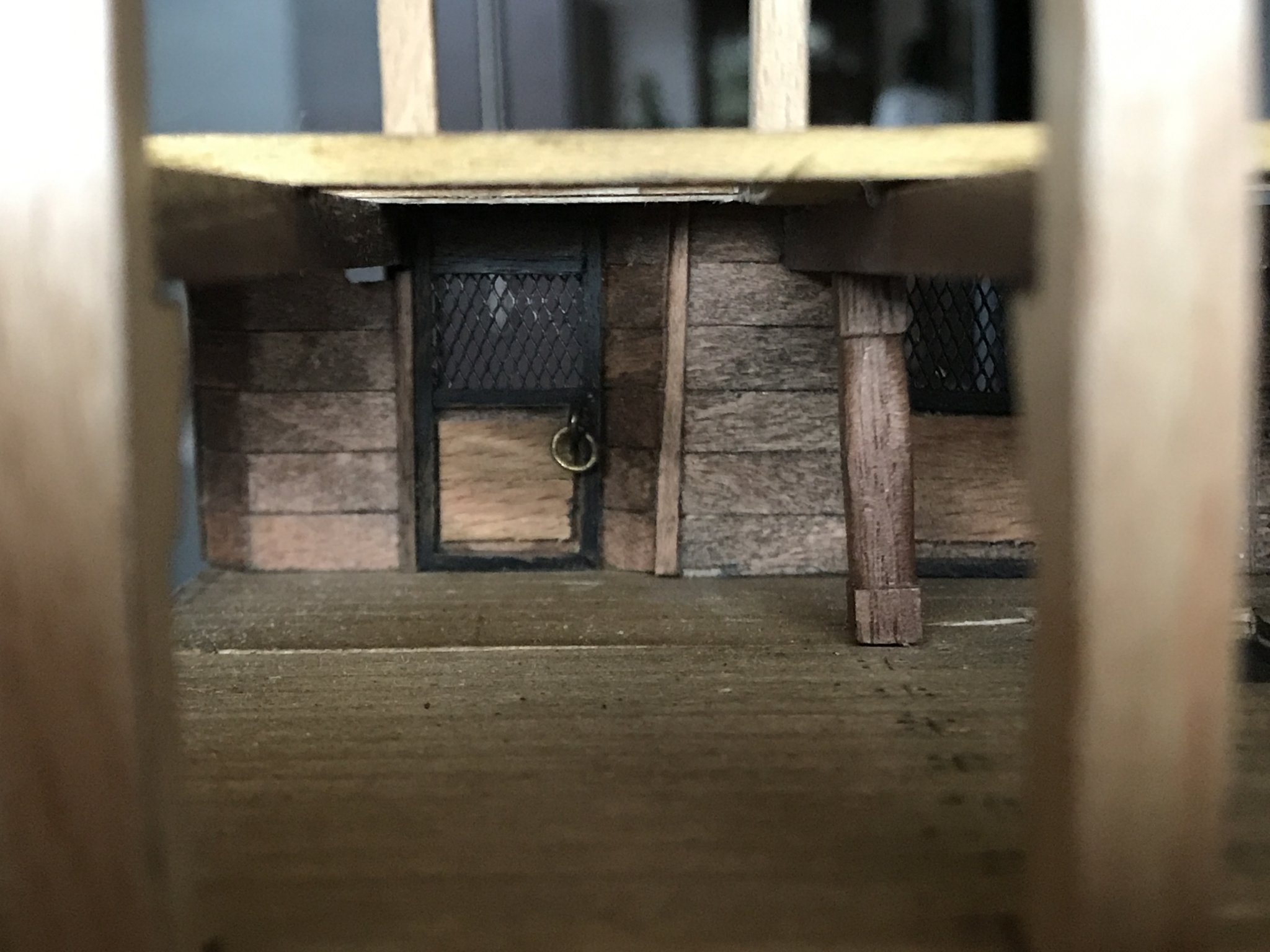
Here I am again lights is not that complicated. I built the rooms acording with the book just one side. And I was able to hide “long” wires behind the walls
-
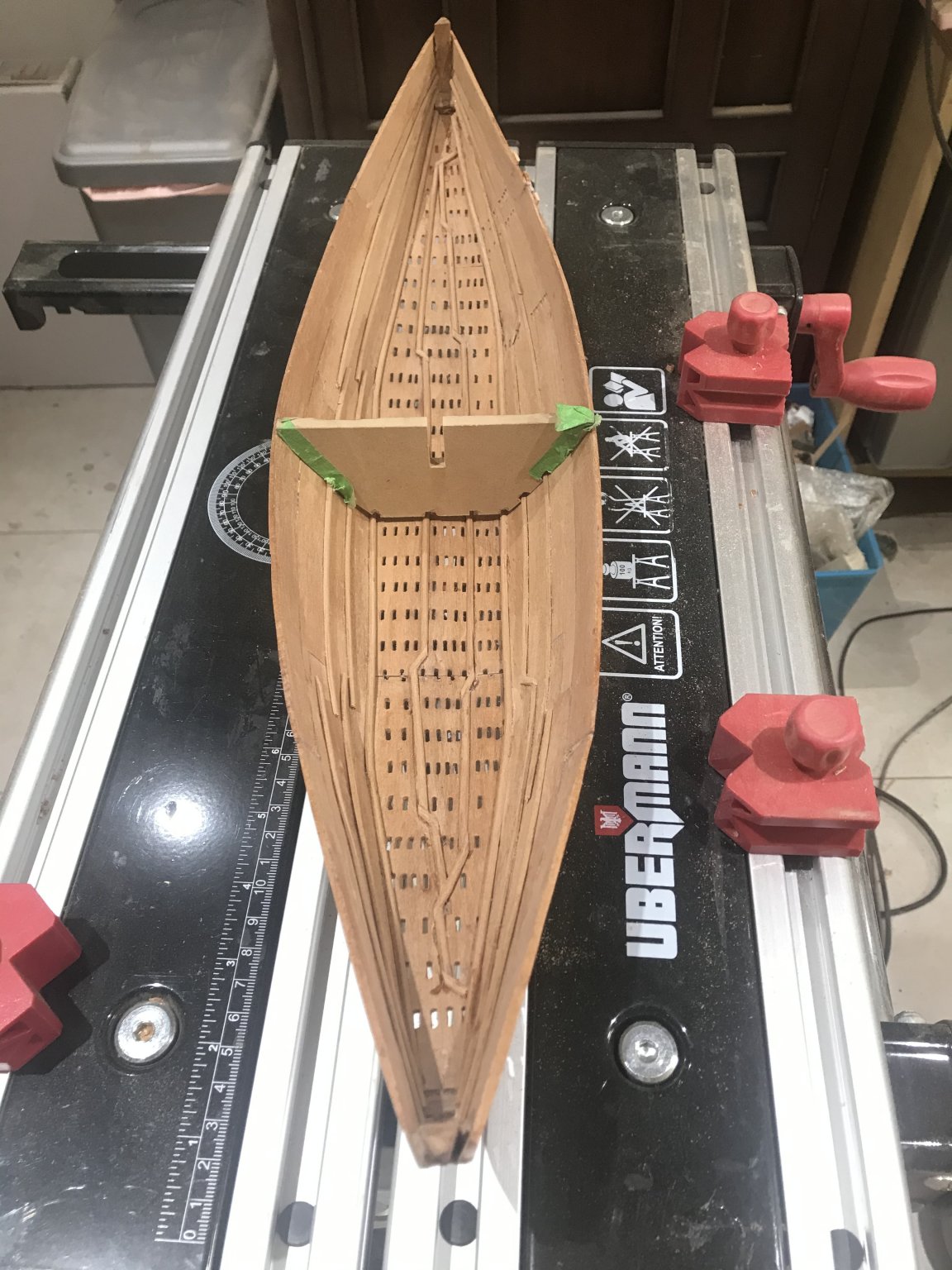
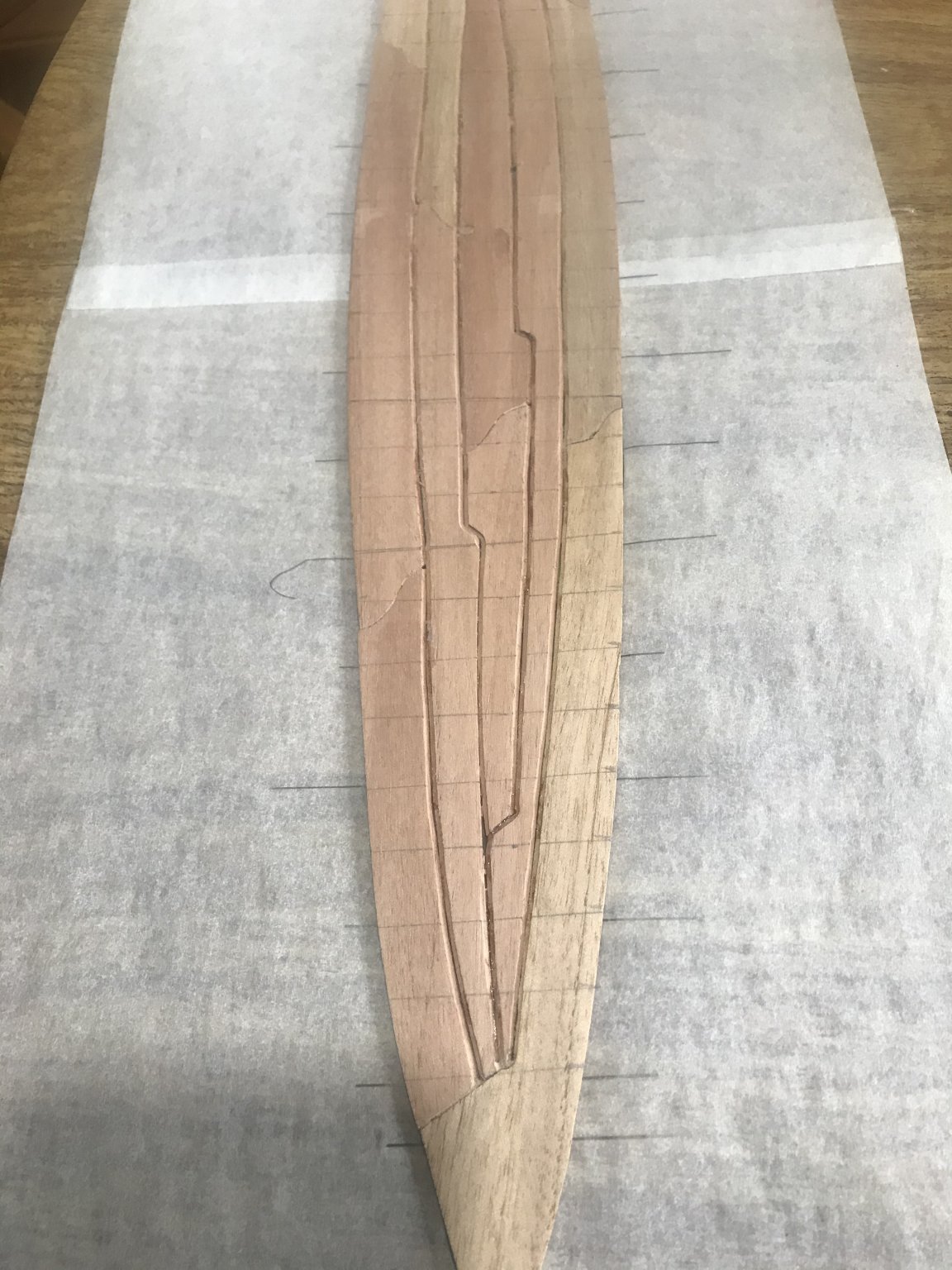
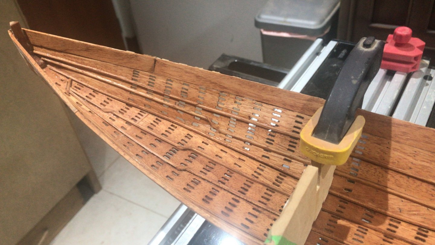
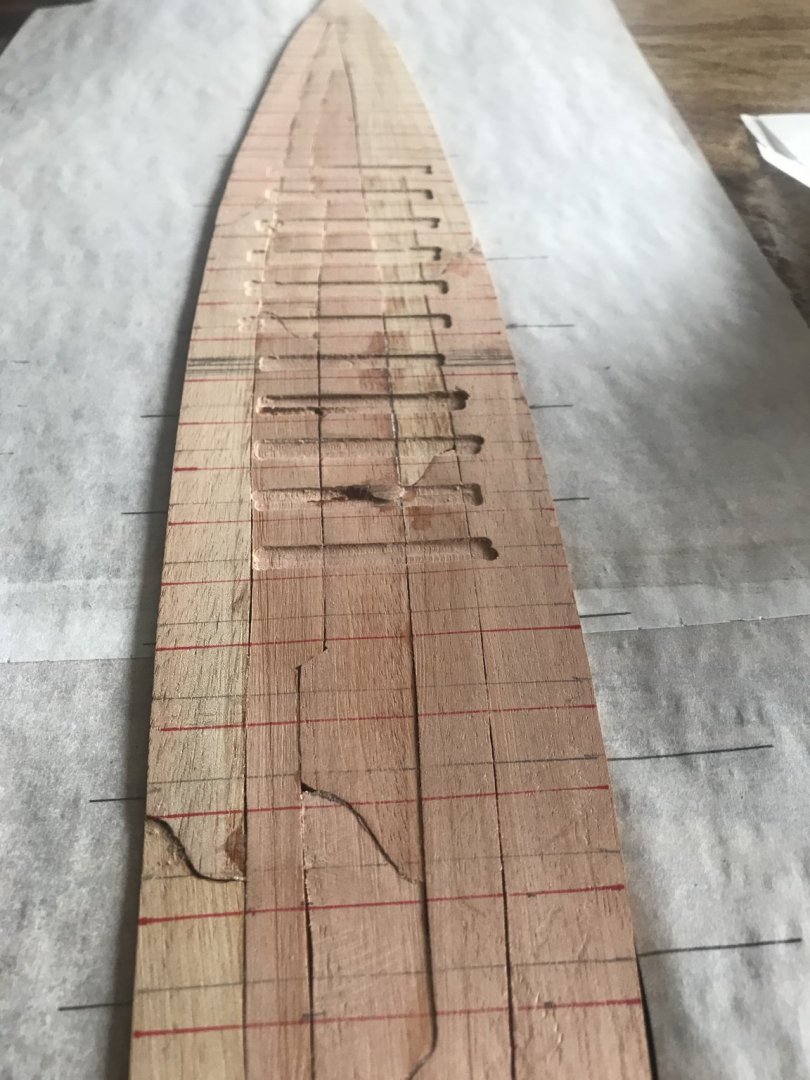
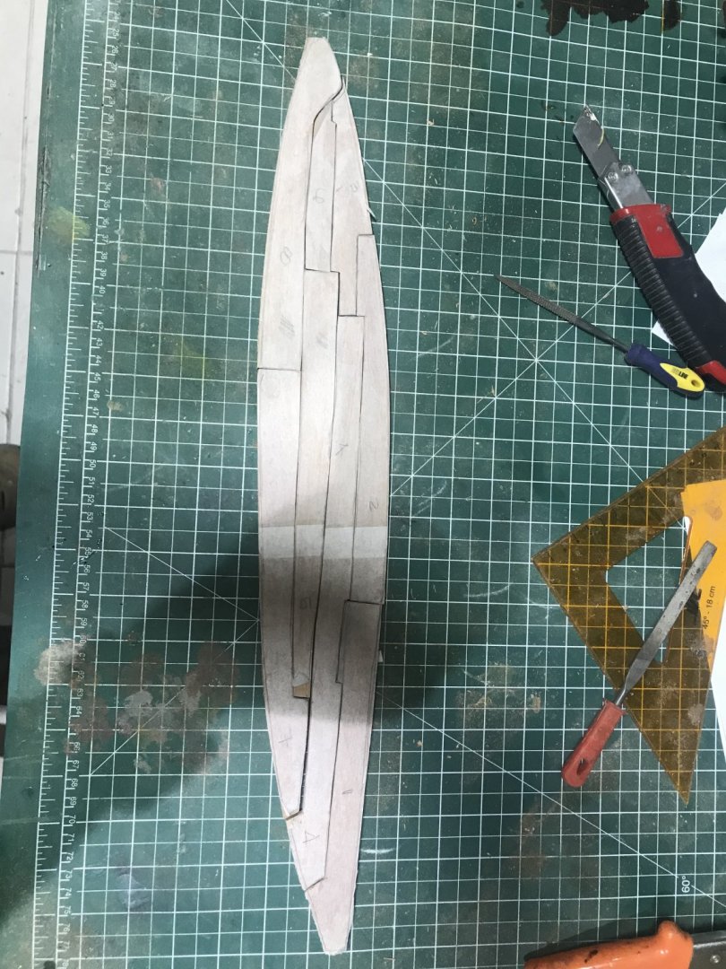
With the 3.2 mm I was able to work the channels an lineal holes..... This face is the one that at the end will be hidden.... Finally I was able to put it in the mold to configure the curve and forms... It is time to start with the laterals...... it will continue


- 158 replies
-
- 8
-
-
- byblos ship
- Egyptian
- (and 1 more)
-
#22 After working with my “second” attempt I realized that: The choice about using two equal thick planks for the two hulls (interior and exterior) was not the best.....The channels left no wood to work with so the lineal holes drilling was a disaster. In conclusion I‘lol keeP the two hulls but the interior will be in 3.2 mm an the exterior will be in 1.2 mm. The “forms” I was using for the planks were not accurate according with the documents I found. Even though we need to create as much “lineal” contact between planks to create “more“ resistance and strength, I was working with “curves” and should be with straight lines....

- 158 replies
-
- 4
-
-
- byblos ship
- Egyptian
- (and 1 more)
-
For me....is a little bit so dark. I would go with something lighter.
-
It is on my list..... i can not wait to see your log
-
I’m far way from some skill modelers in this group. But enjoying learning new things an technics. Thanks a lot and don’t hesitate to ask. I’ll be more than glad to help if I can regards
-
I want to share some real pictures about Khafu boat..... the IRREGULARITIES I made were intentional in order to make it look as much REAL I could

- 158 replies
-
- 4
-
-
- byblos ship
- Egyptian
- (and 1 more)
-
Thanks Phil.. I really enjoy when my work is somehow useful to others
-
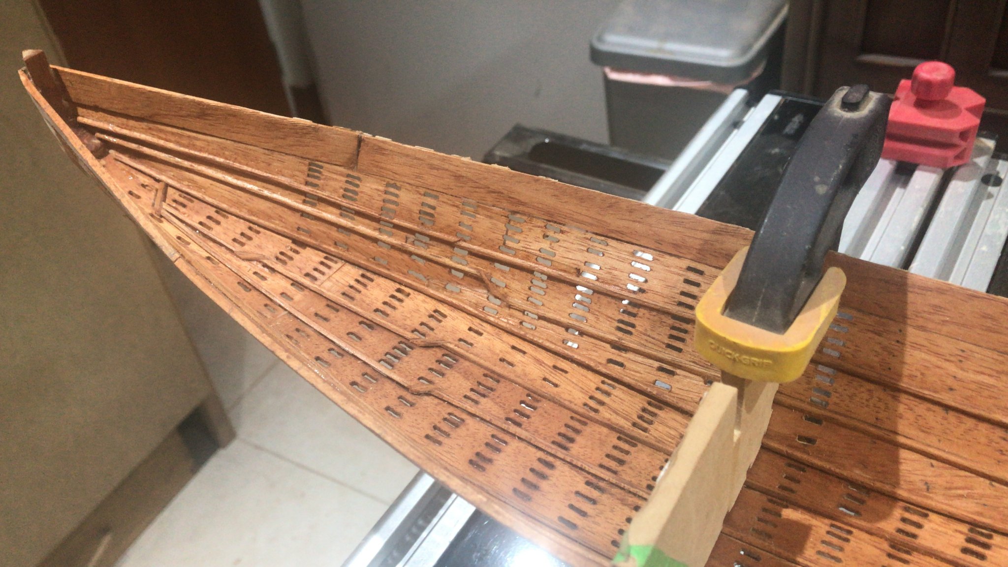
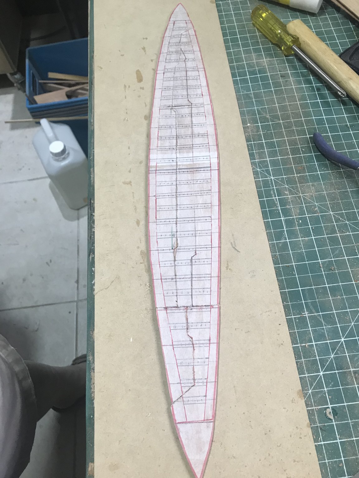
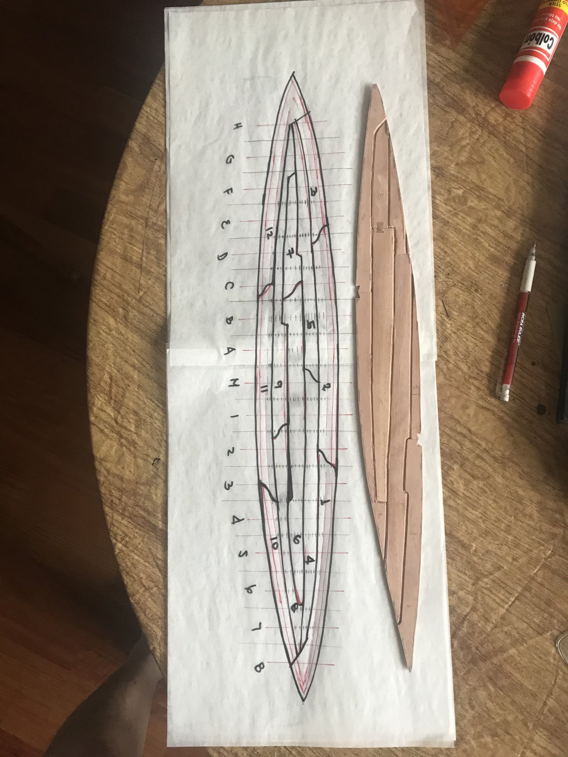
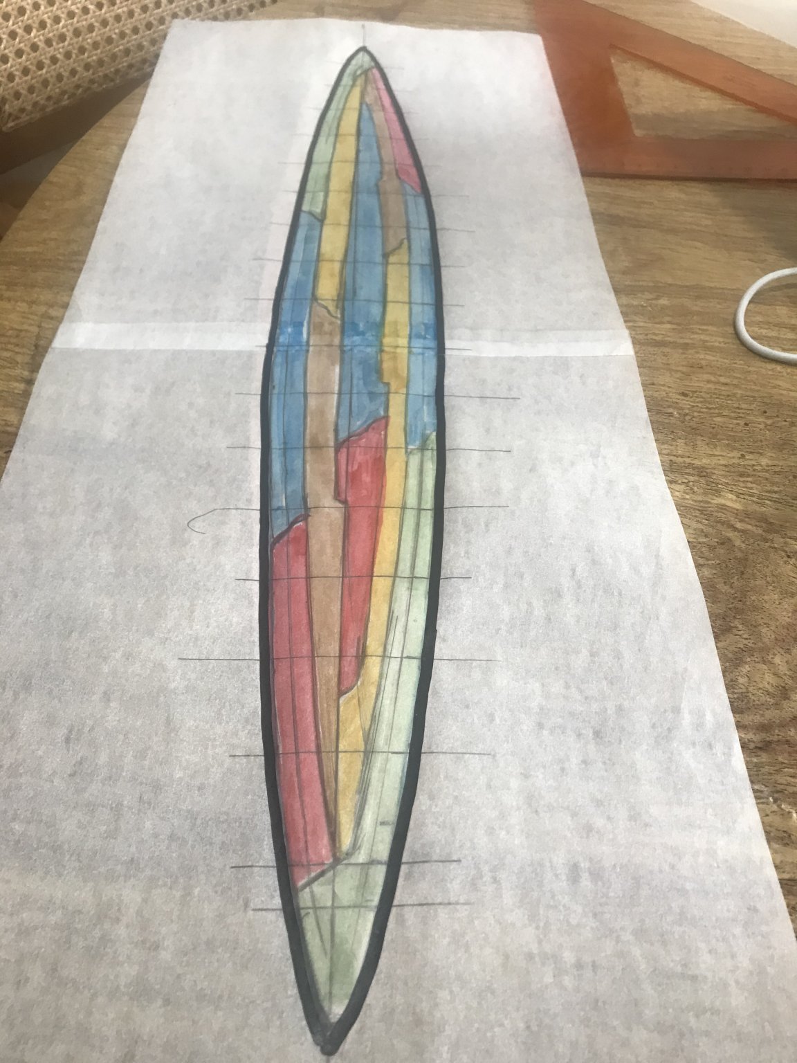
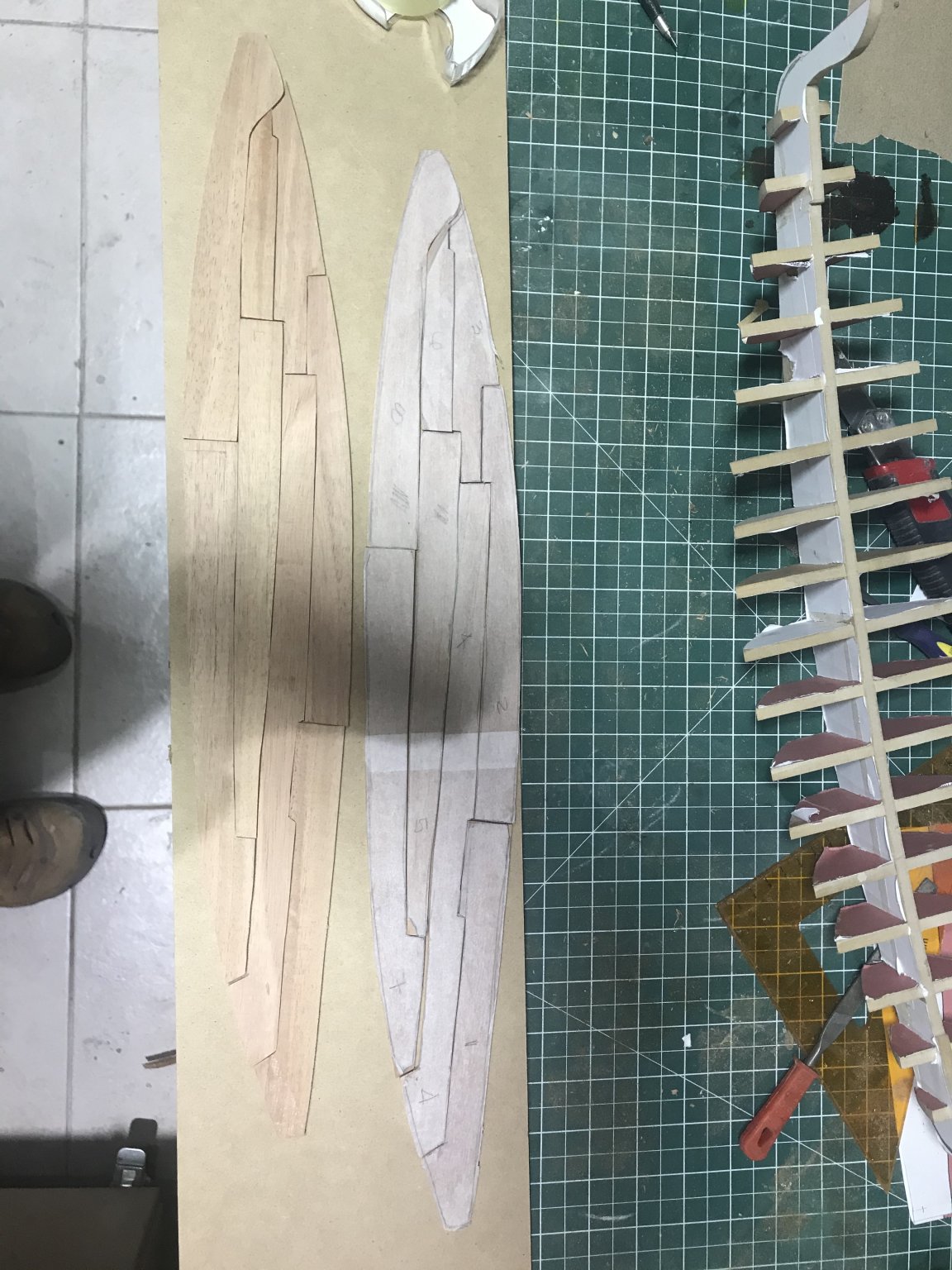
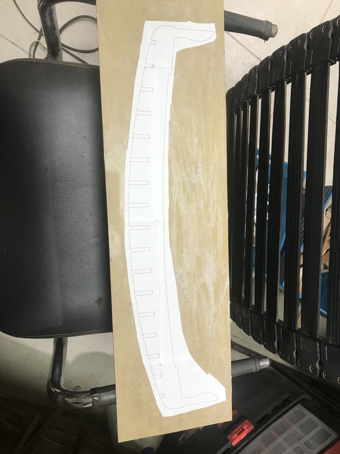
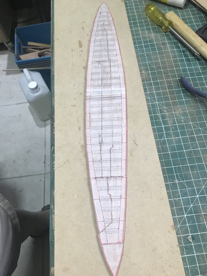
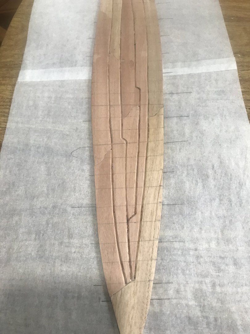
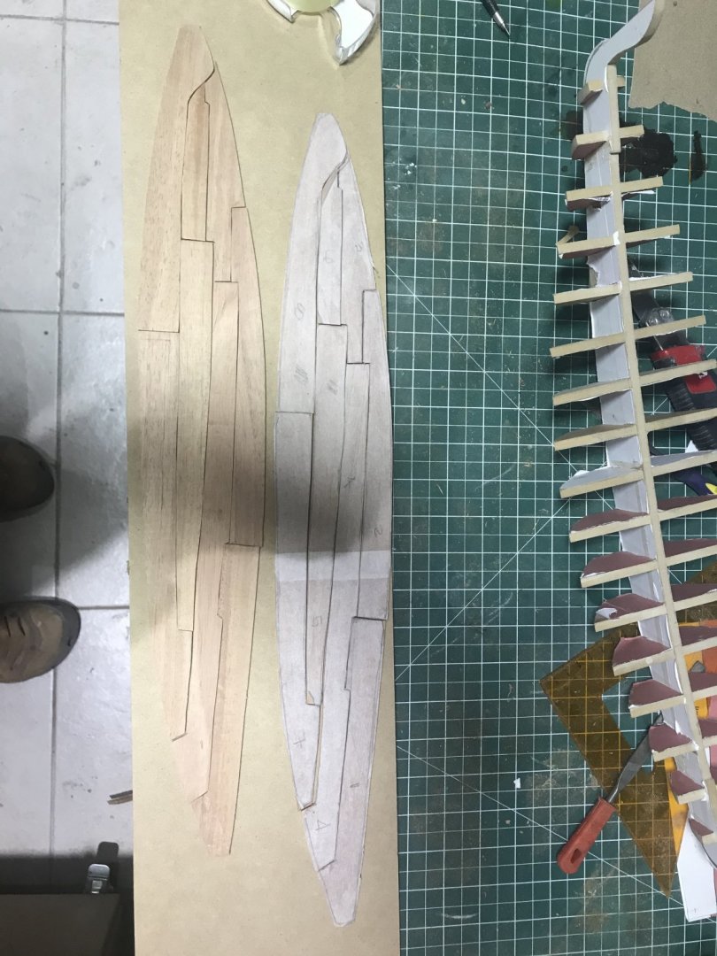
But...... after taking it to my sight.... I realized that the planks “sketch” was out of scale.... so decided to repeat it ...... this is the new comparing with the old one.... The new one is looking better....So I decided to move forward. Using the same methodology...... this the result... I made these littler channel in the joints to insert the battens and in the back side I made some other channels to ”hide” the seams at the time we have to install the exterior hull.
- 158 replies
-
- 7
-
-
- byblos ship
- Egyptian
- (and 1 more)
-
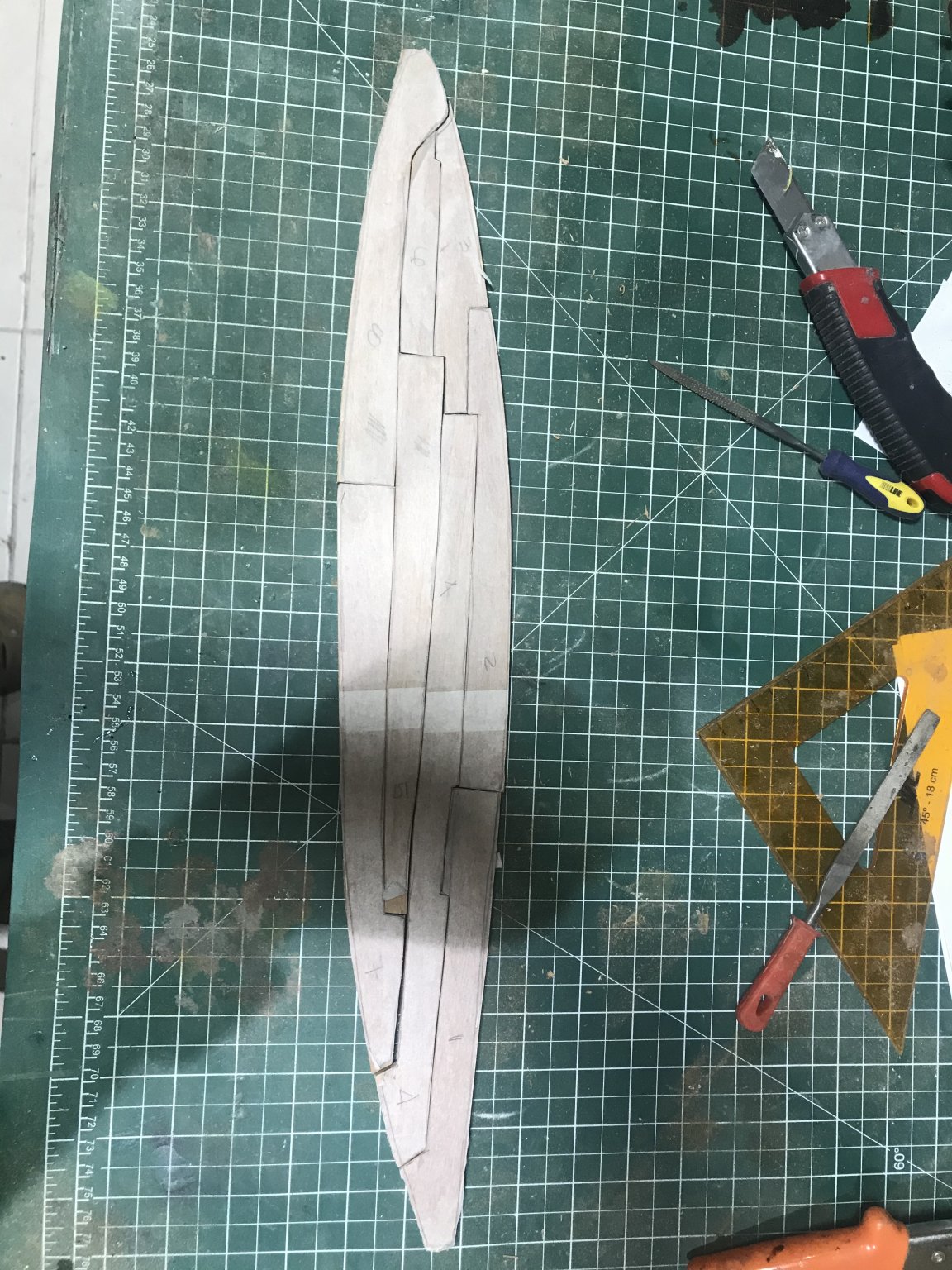
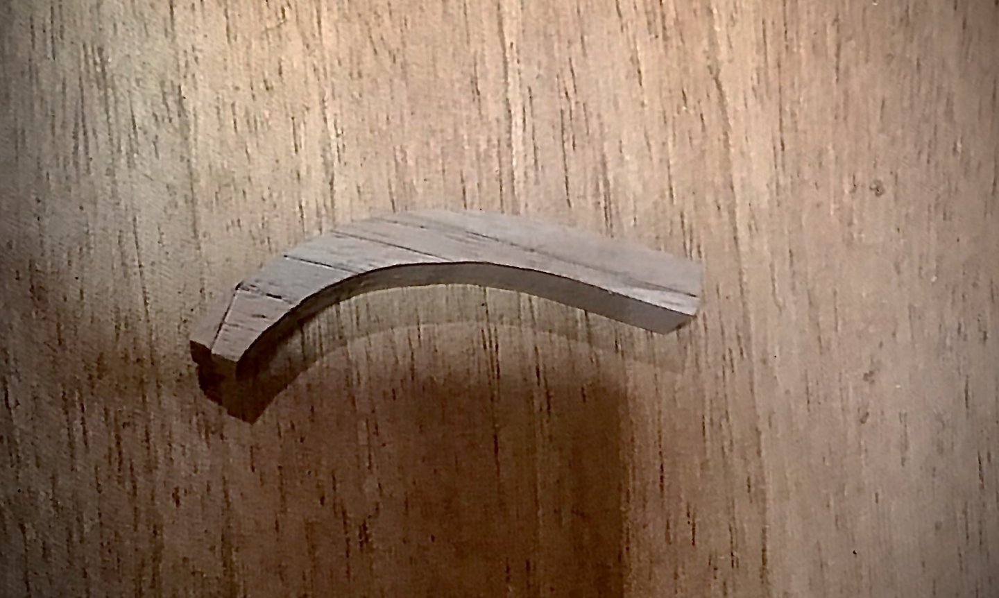
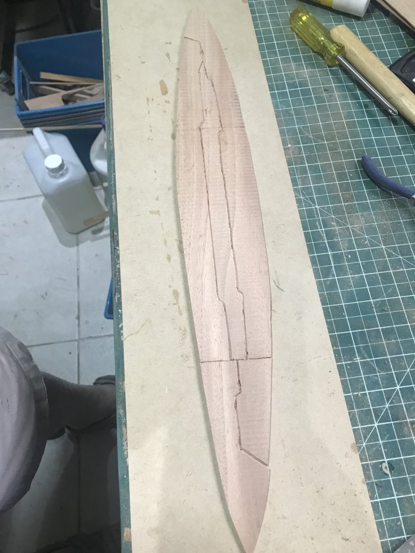
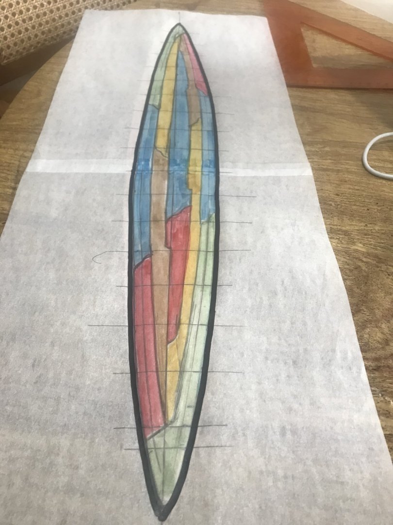
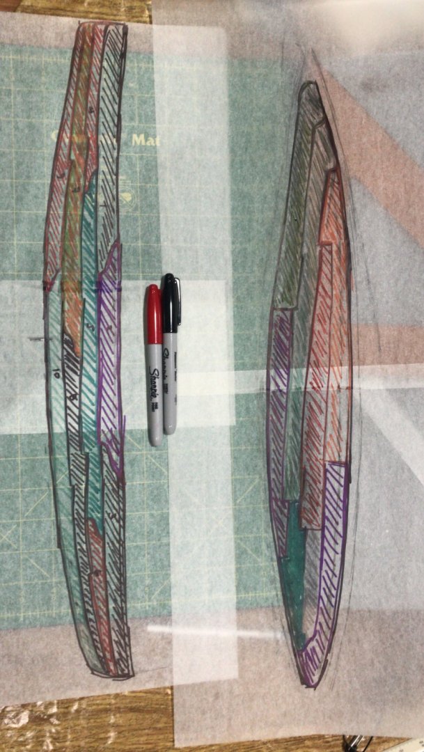
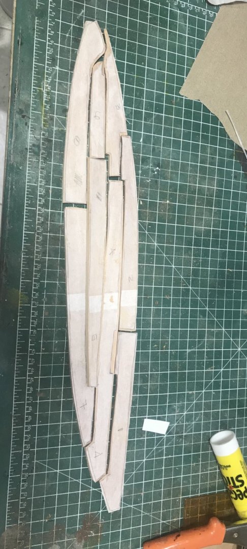
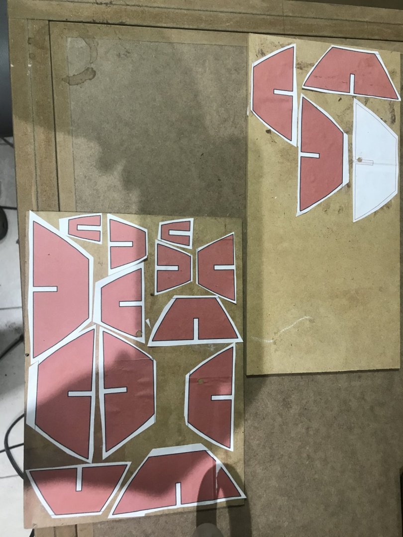
After studying, making questions... and thinking how to solve the “nightmare” “V” channels ( to hold the seams). I decided to “copy” some idea that a friend of mine from Spain Vladimir Herrero had when he built his Keops.... Well it sound very simple but.... believe me it is not...... double planking..... the interior is the one that will have “all” the work....V channels (2), battens (8) and frames The thickness for this scale will be about 4.2 mm. So I took to lumbers 2.1mm thick with double face tape.....to make “identical“ pieces..... But first.....and after seeing how “strange” forms those planks had.... I made a sketch of it. Cut the templates (double lumber jointed with double face tape) Adjusted and separated... We have two “Identical” twins....!!!!!!

- 158 replies
-
- 5
-
-
- byblos ship
- Egyptian
- (and 1 more)
-
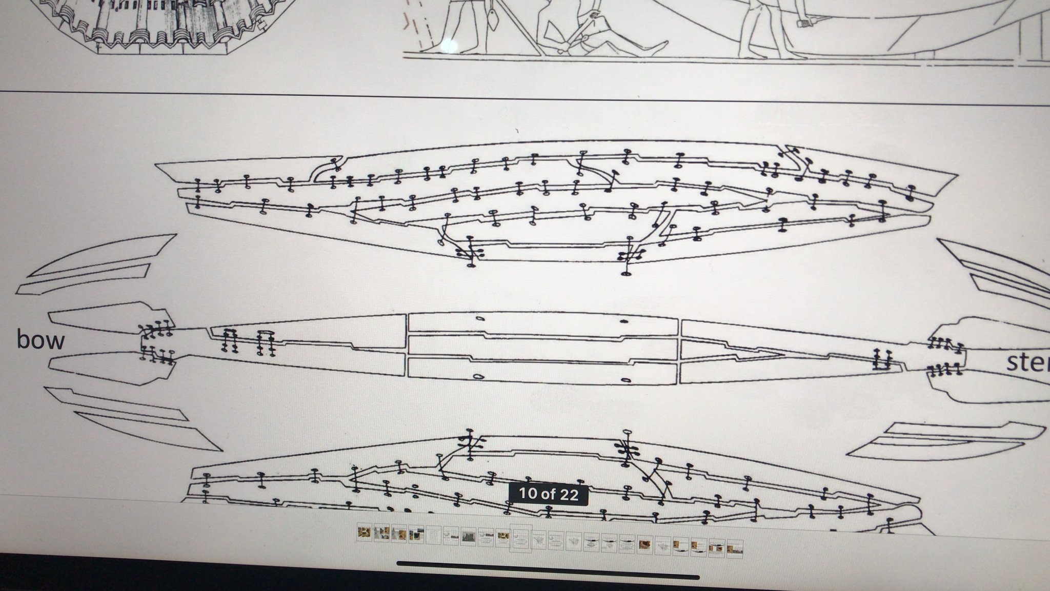
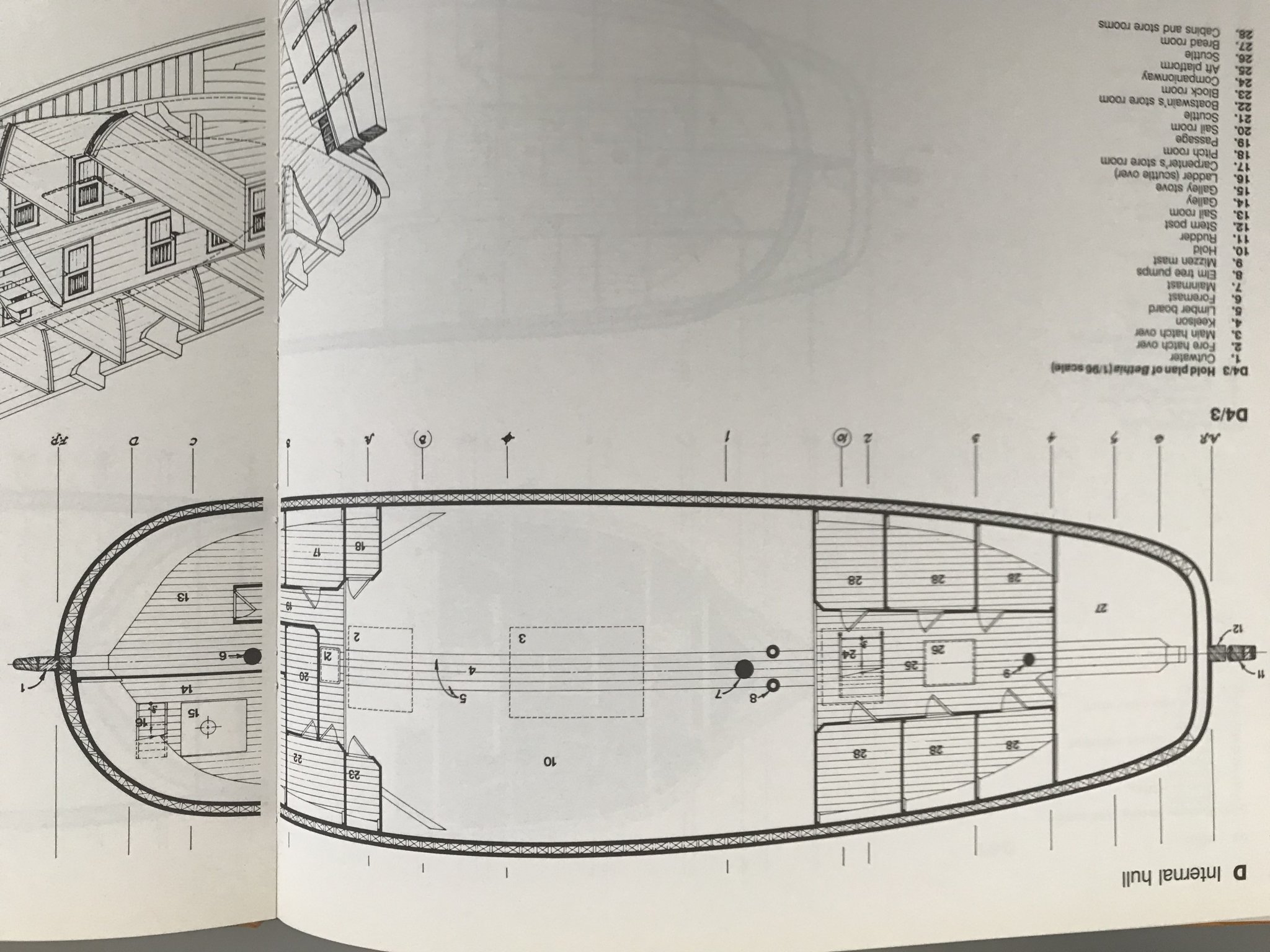
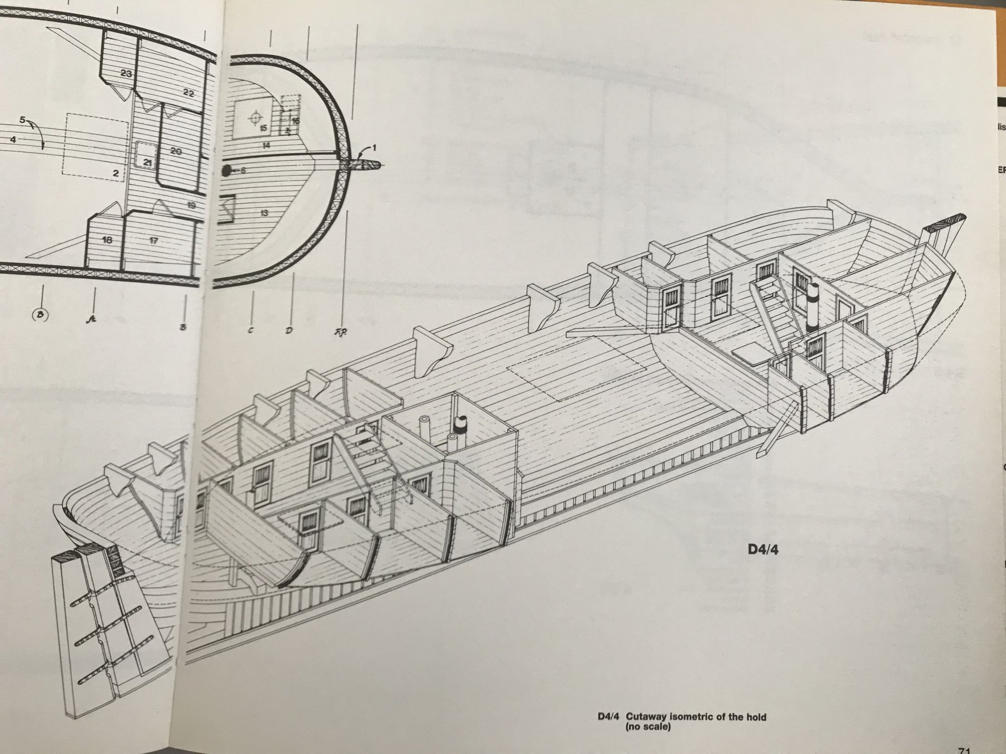
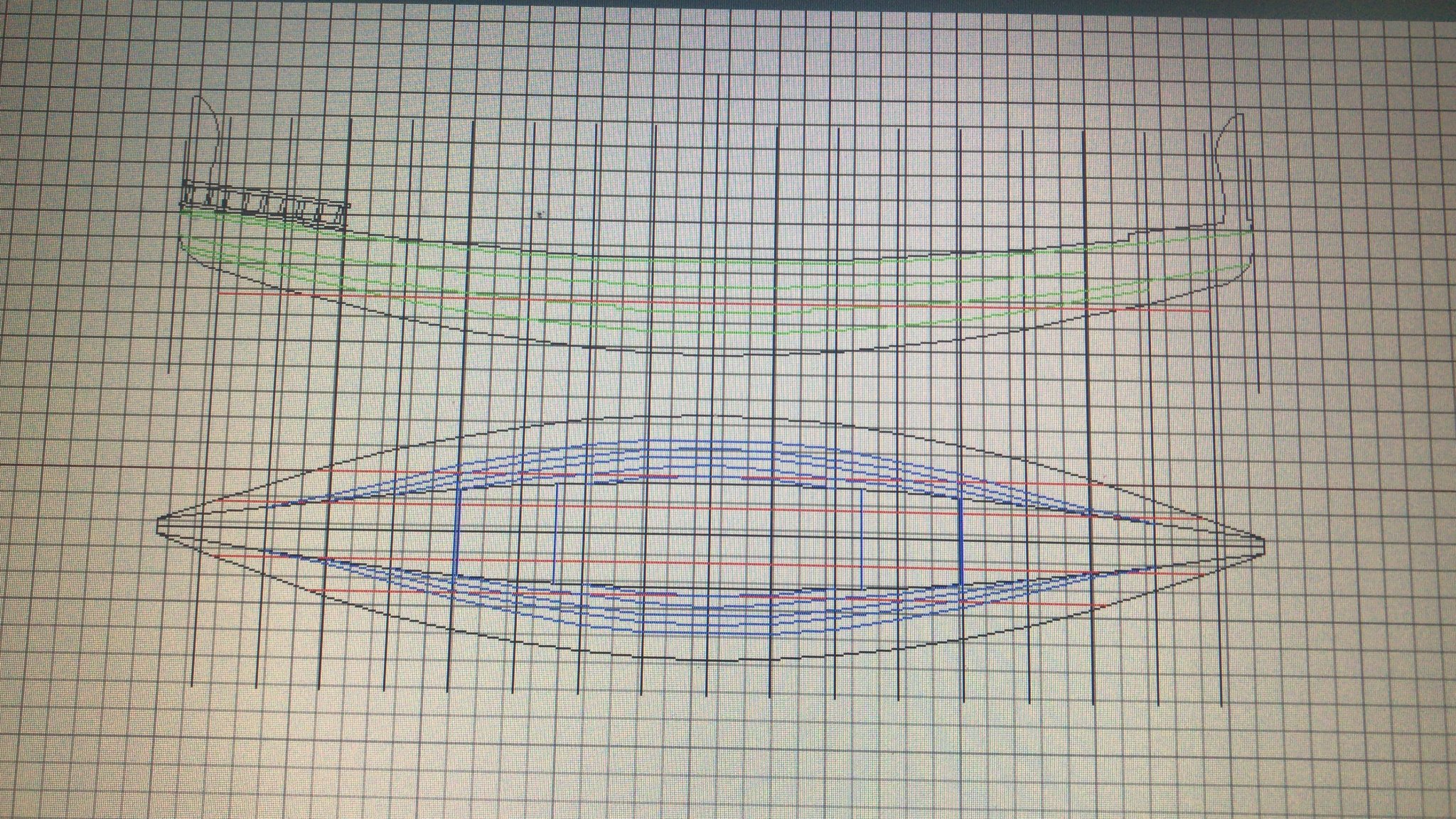
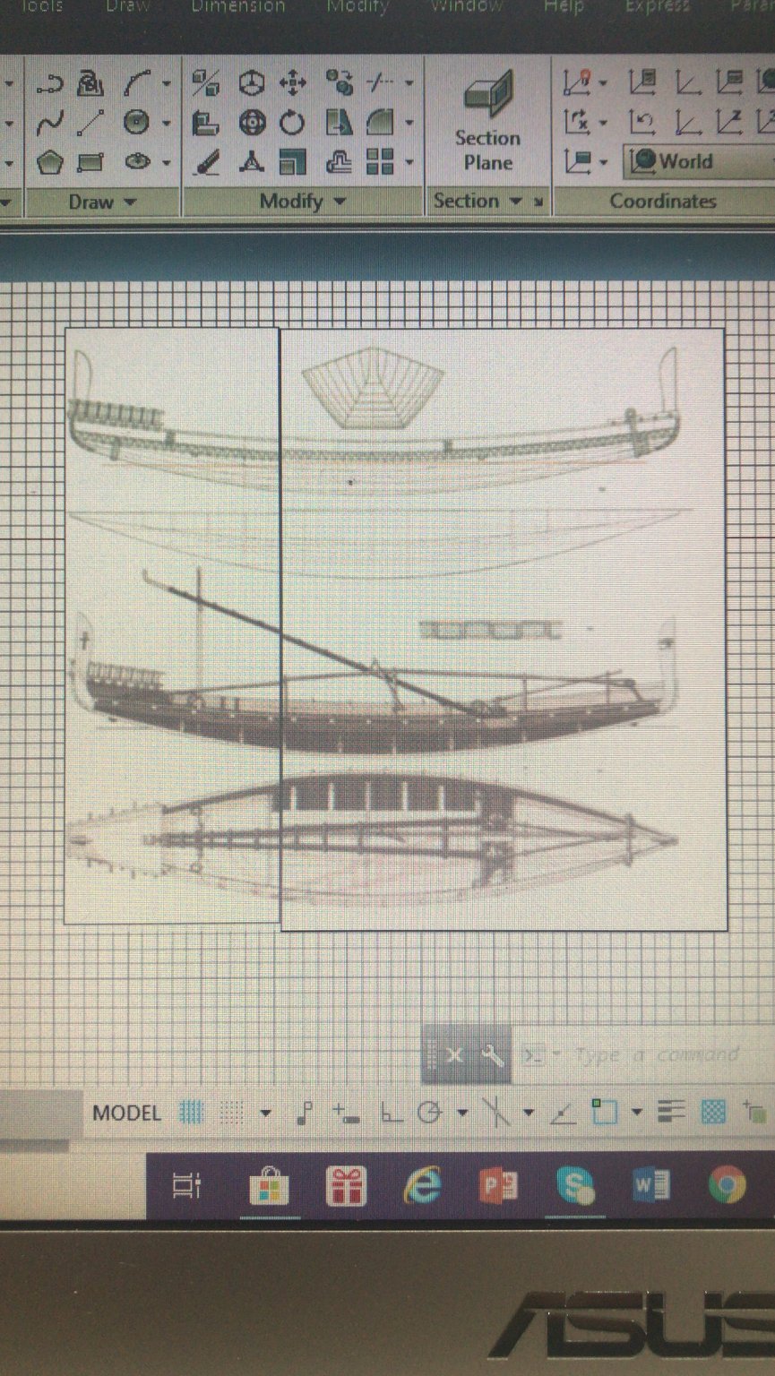
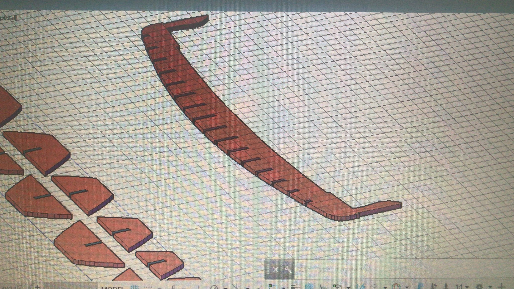
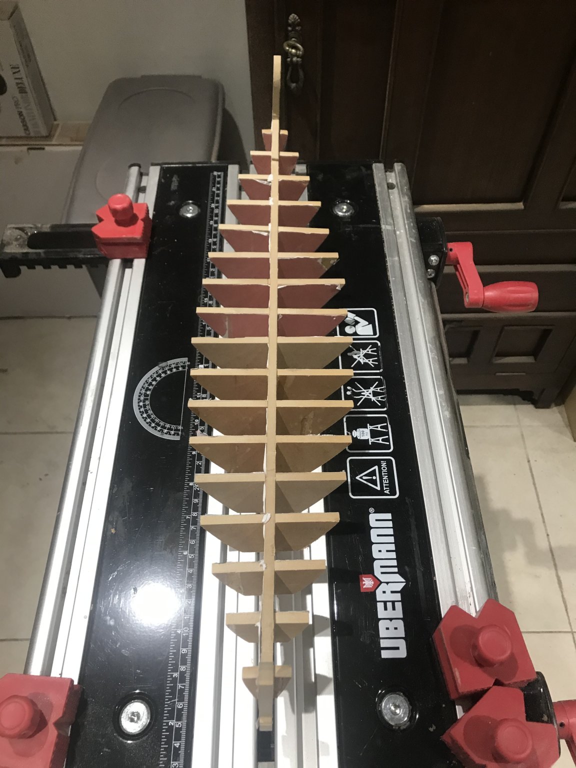
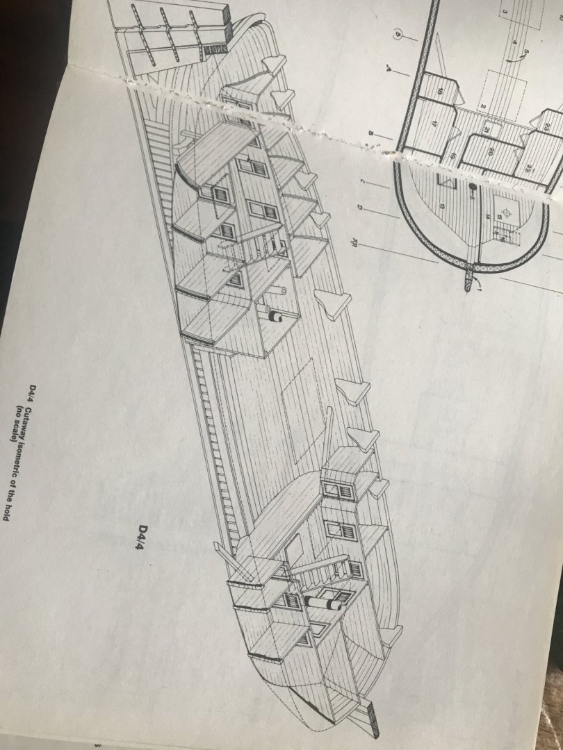
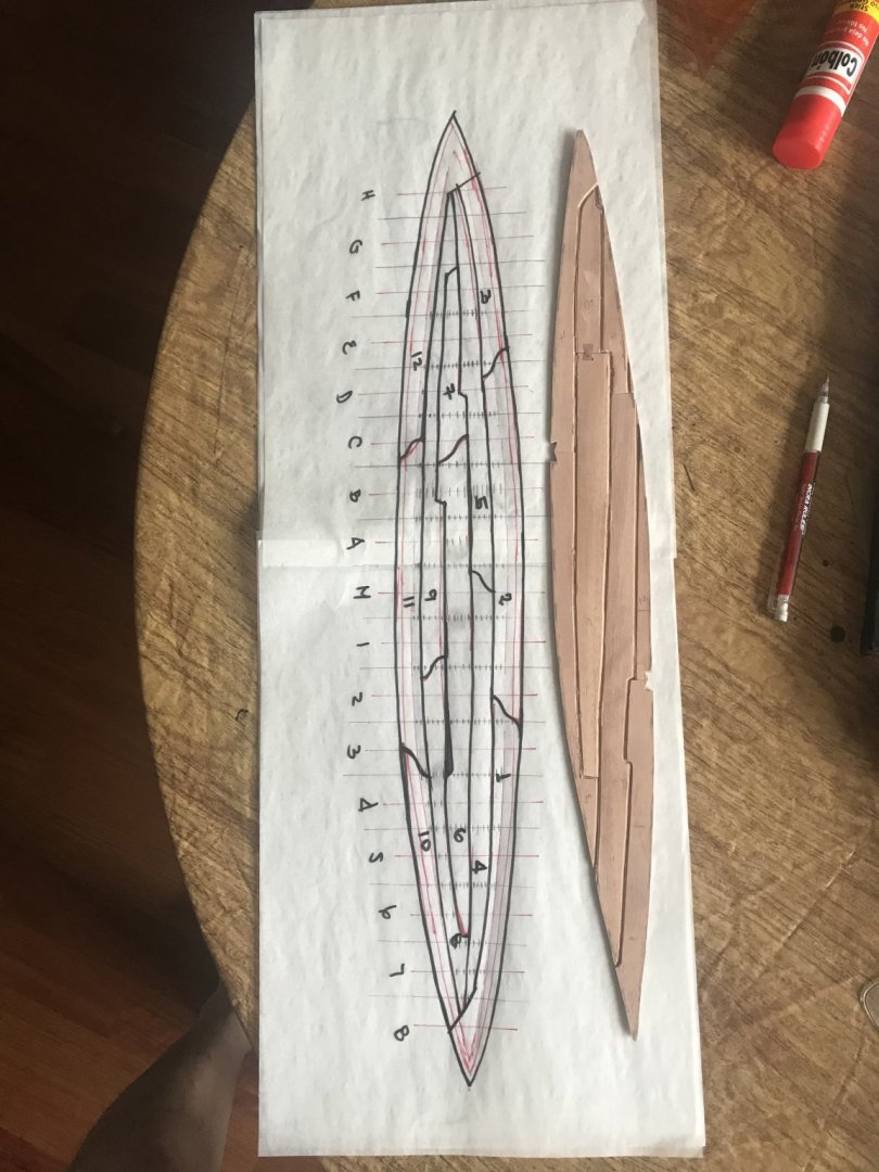
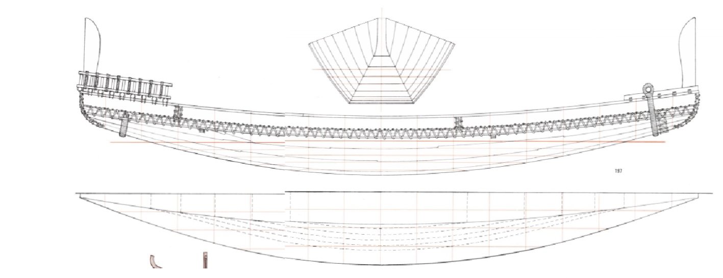
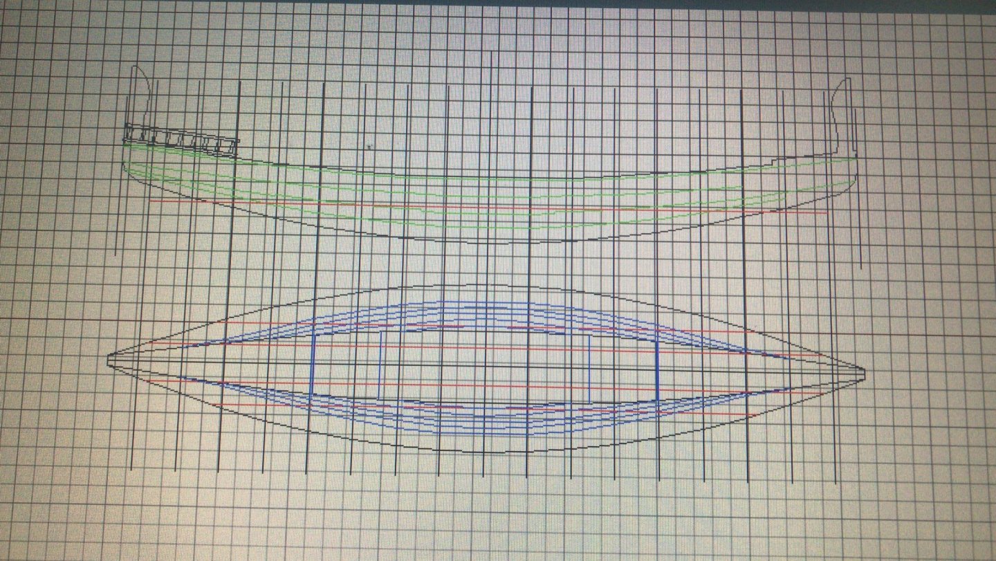
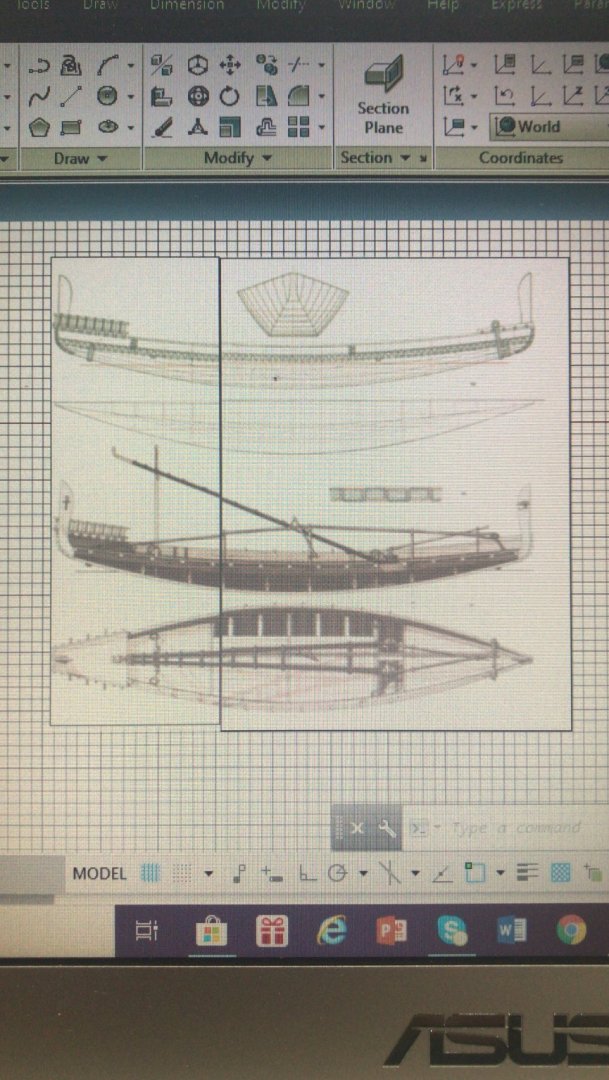
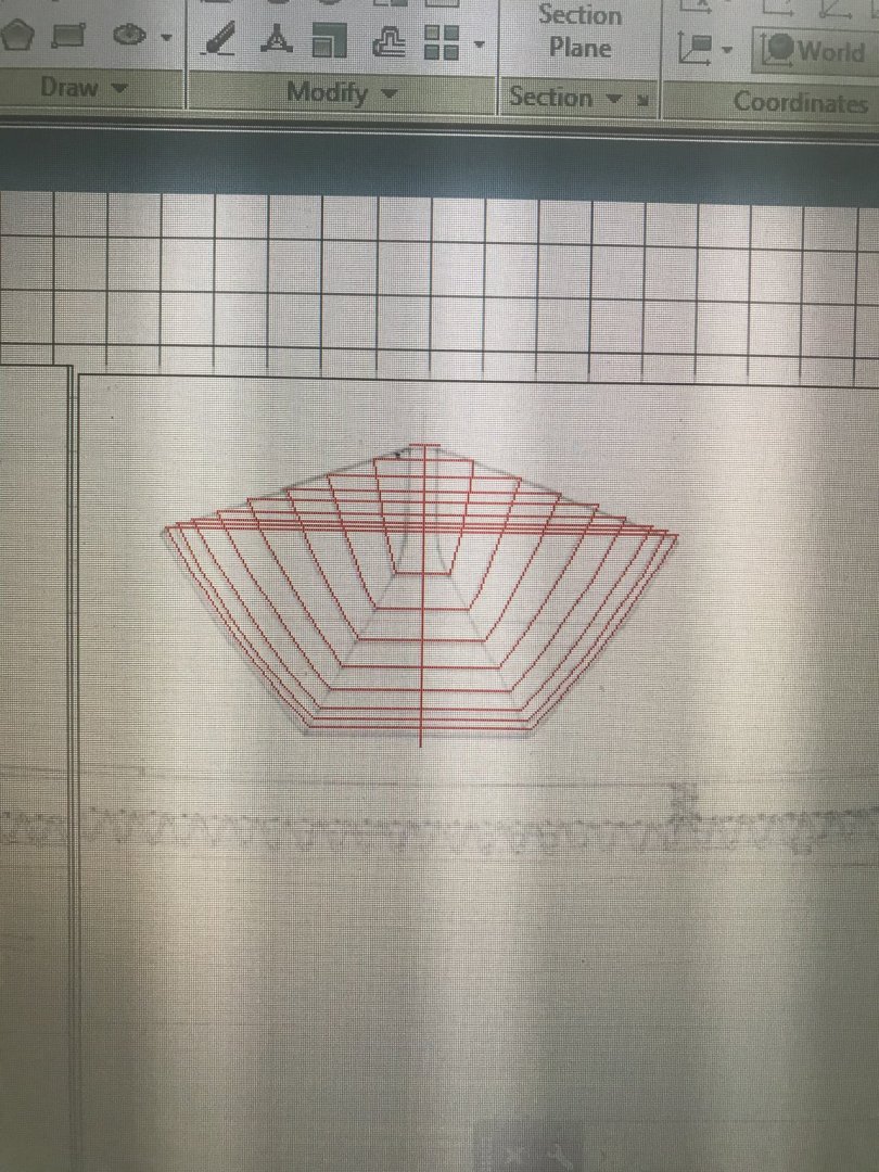
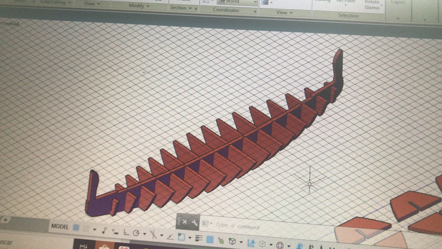
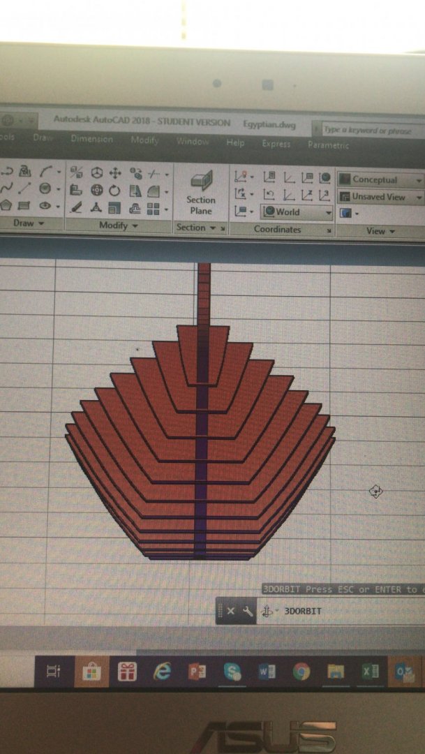
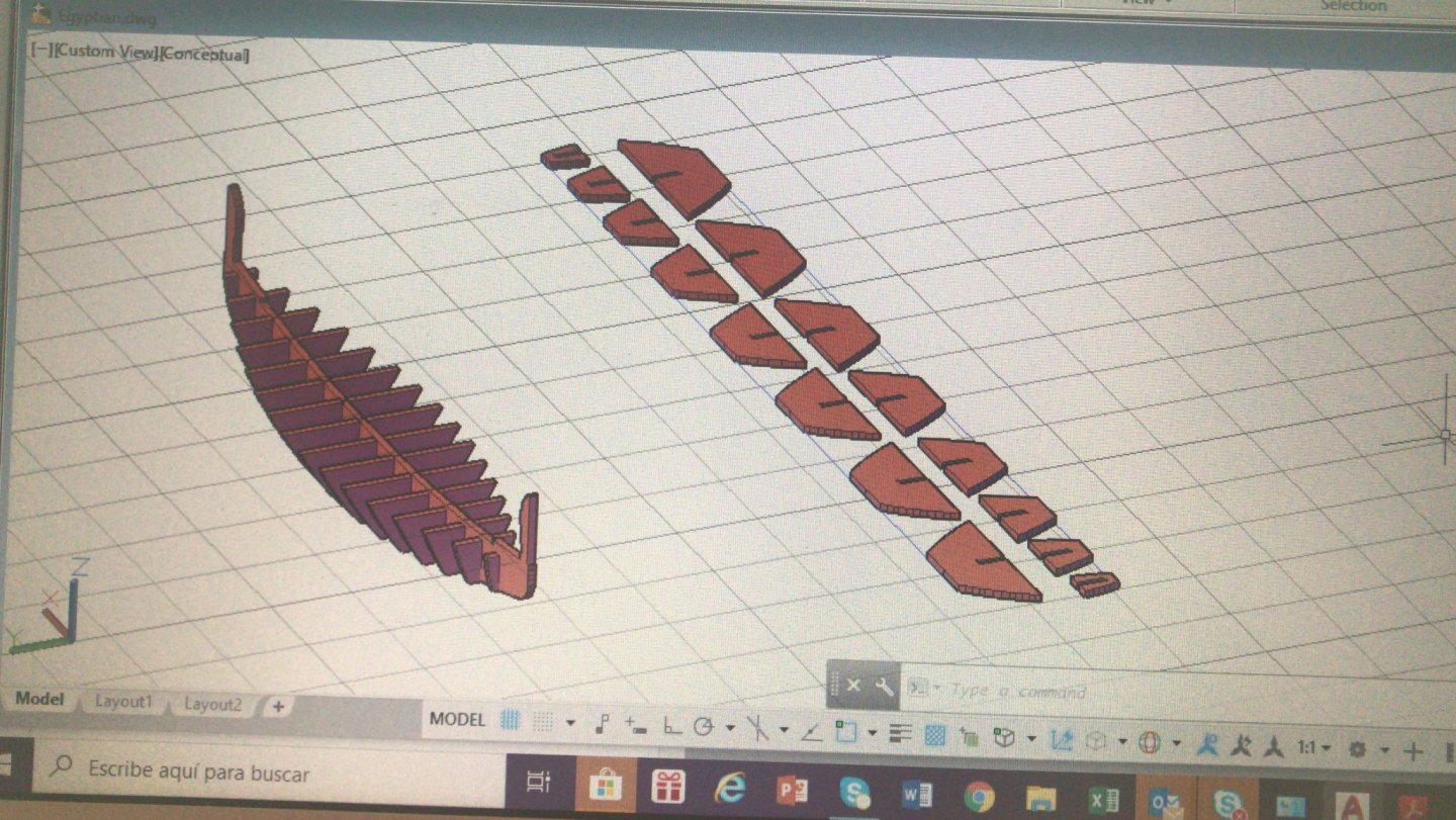
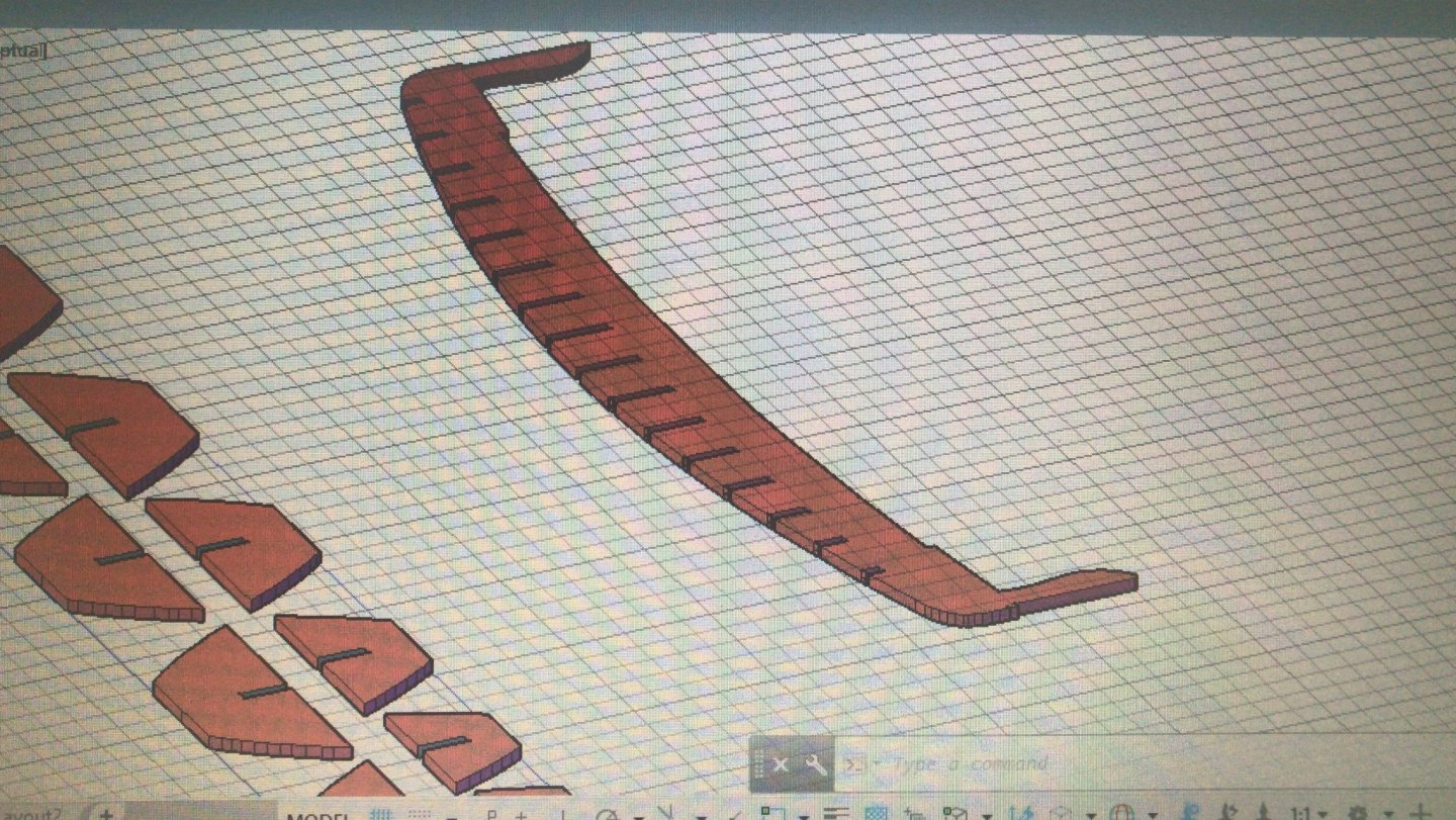
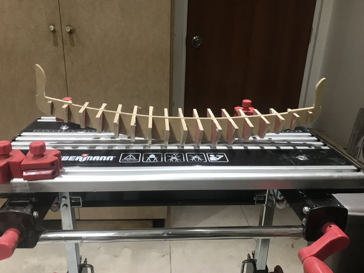
Let’s work a little bit in the real model..... In the Ships of the Pharaoh I found a plan/picture related to this model. I took it, imported the PDF to my Autocad, scaled it to 1:32........ Based in this final plan, I went to the “frames” picture I did the same...... Then.... I built a “ship” with false frames and false keel........all puzzle pieces in three dimensions........ Put them apart ....... and here we go....... with 5 mm MDF I got it!!!!!! The “mold” to start with the real construction.. 17 frames


- 158 replies
-
- 10
-
-
- byblos ship
- Egyptian
- (and 1 more)