shipmodel
-
Posts
941 -
Joined
-
Last visited
Content Type
Profiles
Forums
Gallery
Events
Everything posted by shipmodel
-
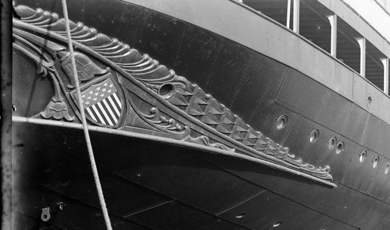
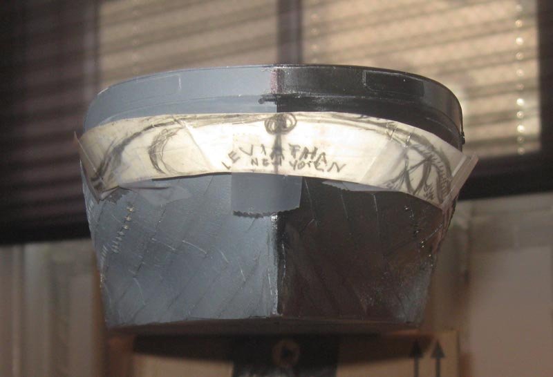
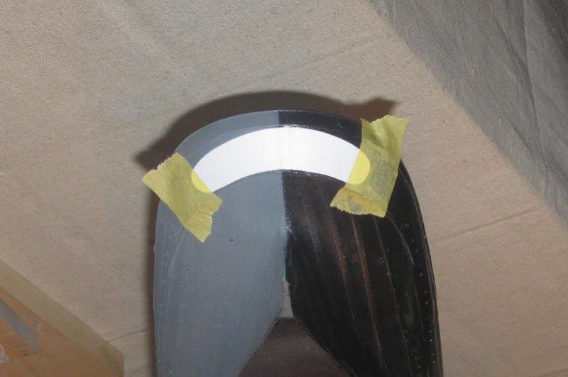
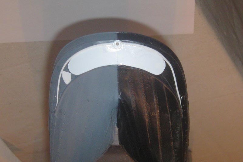
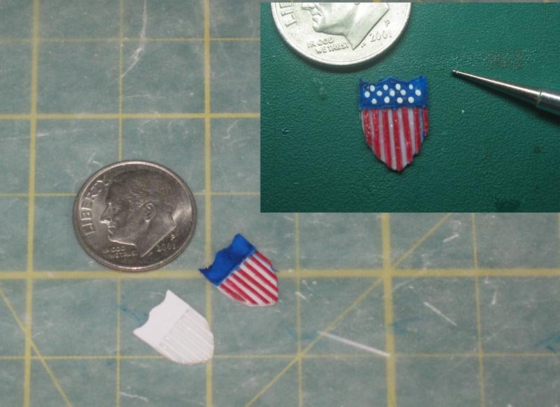
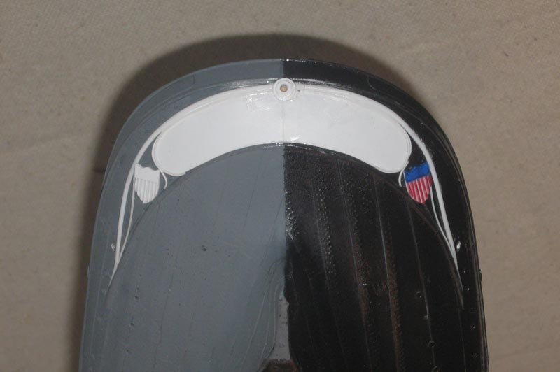
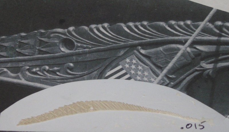
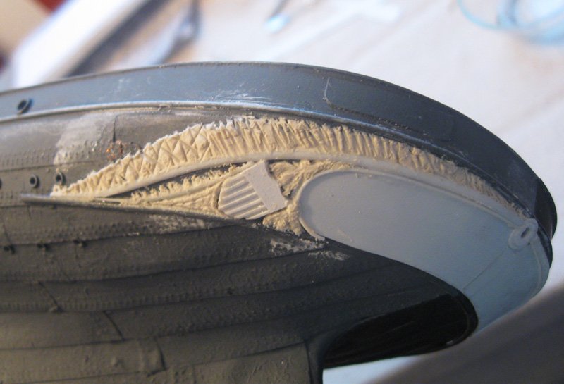
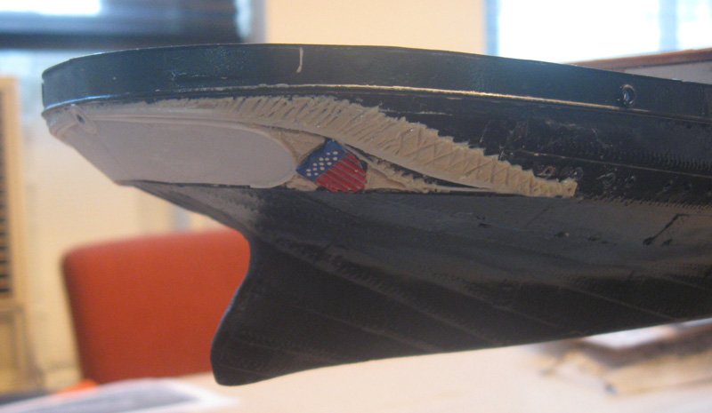
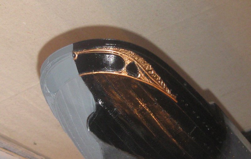
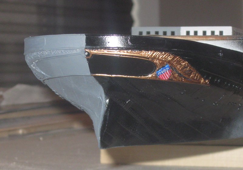
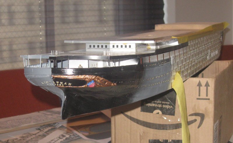
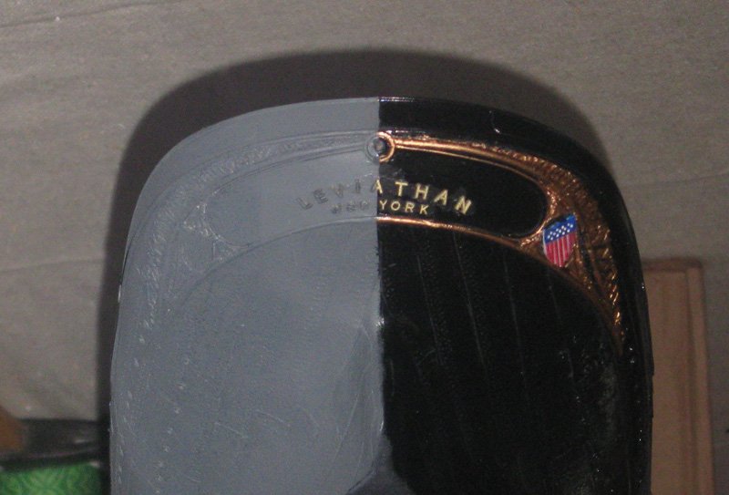
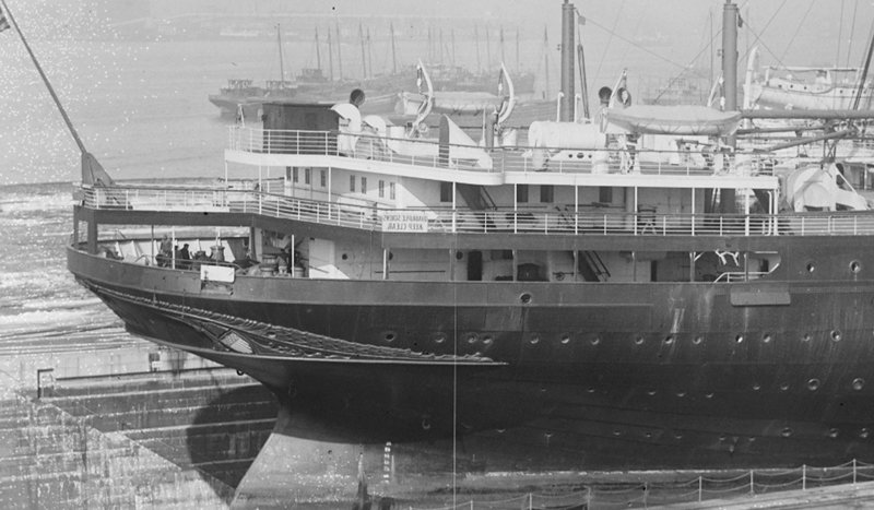
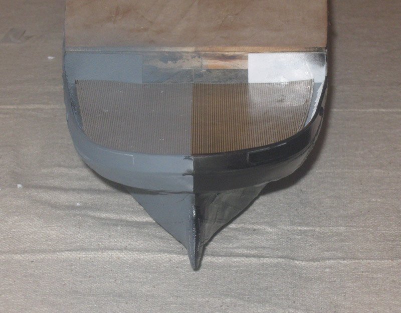
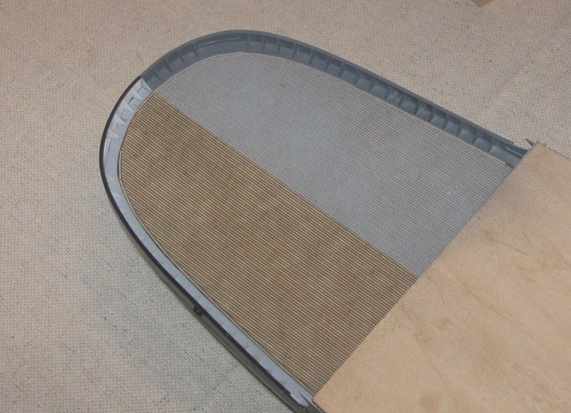
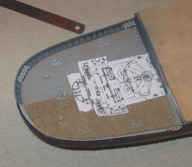
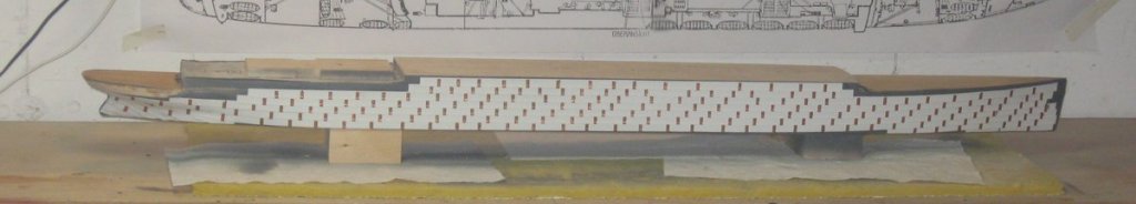
 The final structural element of the lower hull was the decoration under the stern counter. Although the filigree decorations at the bow of the SS Vaterland were removed, these at the stern were retained, with some changes. The name was replaced in the large flat oval section, called a cartouche, in the center, of course, as was the home port. Then the German national shield was replaced with the American one. The rest appears to have been kept as is. A detailed photo shows that the filigree has a bas-relief fringe on top made up of various feathery and leafy shapes above a large gently curved vine stem. Below the central stem are some smaller stems that lead to flower heads framing the shield and some small waves to fill the remaining space. At no point does it look to be more than three inches thick. There was no way that I could generate the required layout of the two-dimensional shape that would fill the 3-dimensional compound curves of the counter. Using a very low-tech solution I wrapped the counter in a strip of stiff paper, then trimmed it back till I got something that basically fit. Taping it to the hull I roughly drew in the major elements of the decoration. Some of the derived shapes were quite surprising. Using the drawing as a guide, I started with the flat oval cartouche for the name. Again, I cut a rough piece of paper and repeatedly trimmed it until I had an oval that fit between the upper and lower moldings of the counter, and which was symmetrical when I folded it along the centerline. When I was satisfied I used the paper as a pattern for the plastic piece. It was checked and rechecked, trimmed and sanded a bit, then secured in its place. The hawse hole at the top center was built up from several sizes of punched and drilled discs. The large vine pieces were laid out so they ran along the top of the cartouche then curved and tapered into the lower counter molding. A paper pattern for the shield was cut and test fitted into its space. The two shields were cut to the pattern out of 0.015” sheet with scallops along the top edge. The blue field was set on top, made from 0.010” sheet. The seven red stripes were cut from 0.010” x 0.030” strip and glued in place. The pieces for the colored shield were pre-painted before installation, while the ones for the troop ship were not. I made no attempt to put 13 stars into the field that was so small. I just dotted the field with white using a tool from a nail decorating set purchased at the drug store. The blank shield was permanently attached, but the colored one only tacked in place. Using them as landmarks the smaller vine stems were curled to shape and installed. I took a page from that wonderful Czech artist, Doris, from this site, and decided to mold the decoration in clay. I have tried Sculpey, which Doris uses under the name of Fimo, with very mixed success. I don’t like the process of baking it. I decided to try an air-dried clay instead. I was looking for some on the internet when I stumbled on a store in my neighborhood that sells school supplies. Here I found a number of inexpensive supplies and tools, including a tub of water-based, air-dry clay. Two pounds for only a few dollars. Although this is much more than I will ever use, the price was below that of smaller quantities on line. I took a small amount of the stiff compound and softened it with a drop of water. After some kneading it made a nice, supple, dough. I rolled it into a long rope, then flattened the rope with a curved spatula to about 1mm thick on a scrap piece of styrene. Using the edge and corners of the spatula I found that I could approximate the carvings, although I made simplified triangular patterns where the decoration actually has leaves. I left the test piece to dry overnight. In the morning it was dry and hard and had not deformed or shrunk. That was the good news. The bad news was that it did not adhere to the plastic and it was extremely brittle. Further experiments followed. It turned out that the first problem was solved by softening the clay with white glue instead of water. The pliability was the same, but it held on well to the plastic. There was some more flexibility when dry, but nowhere near enough to allow me to make the decoration off the model, as Doris does, and then transfer it. I laid a clay rope onto the model above the main vine, flattened and shaped it in place. The other sections of the decoration were done the same way. In this shot the decoration is just starting to dry and you can see the upper edge turning white. With a small brush I painted the clay with water. This kept it soft and also smoothed the surfaces. The edges were defined and any excess clay was cleaned up The next day the clay was painted with wood hardener which sealed and strengthened it. Then the liner side was painted gloss black and the troop ship side painted in primer grey. Liquid gold leaf was carefully hand painted on the liner side decorations before the colored shield was permanently attached. Tiny letters were sourced on line. I could have made up decals, like the windows, but I wanted the texture to show through the camouflage grey paint. The larger letters are 1/8” tall (2 feet) for the name and the smaller ones are 3/32” (18 inches) for the home port. They were painted off the model before being attached. So here is the model in its bipolar glory in a shot from low on the starboard stern. After this I continue building in and up. Although it may seem that I am building quickly, this is somewhat because I started the build log almost three months after the model construction started. I am catching up steadily, with these last photos taken at the beginning of October. When I do, the reports from the shipyard will slow down considerably. Like me. Until then, Happy Thanksgiving to all, whether this is your holiday or not. Dan
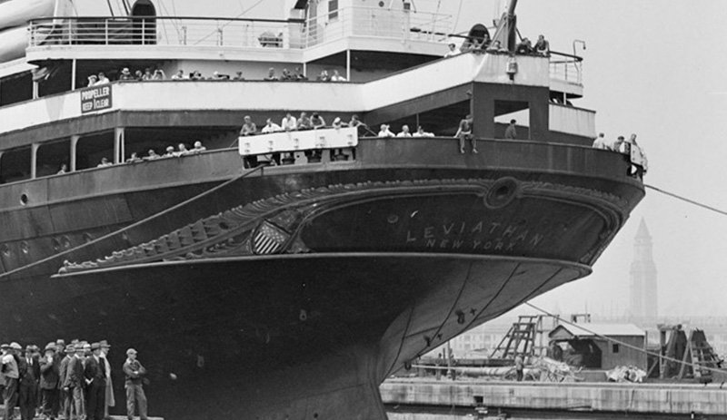
- 238 replies
-
- 23
-

-
- leviathan
- troop ship
- (and 2 more)
-
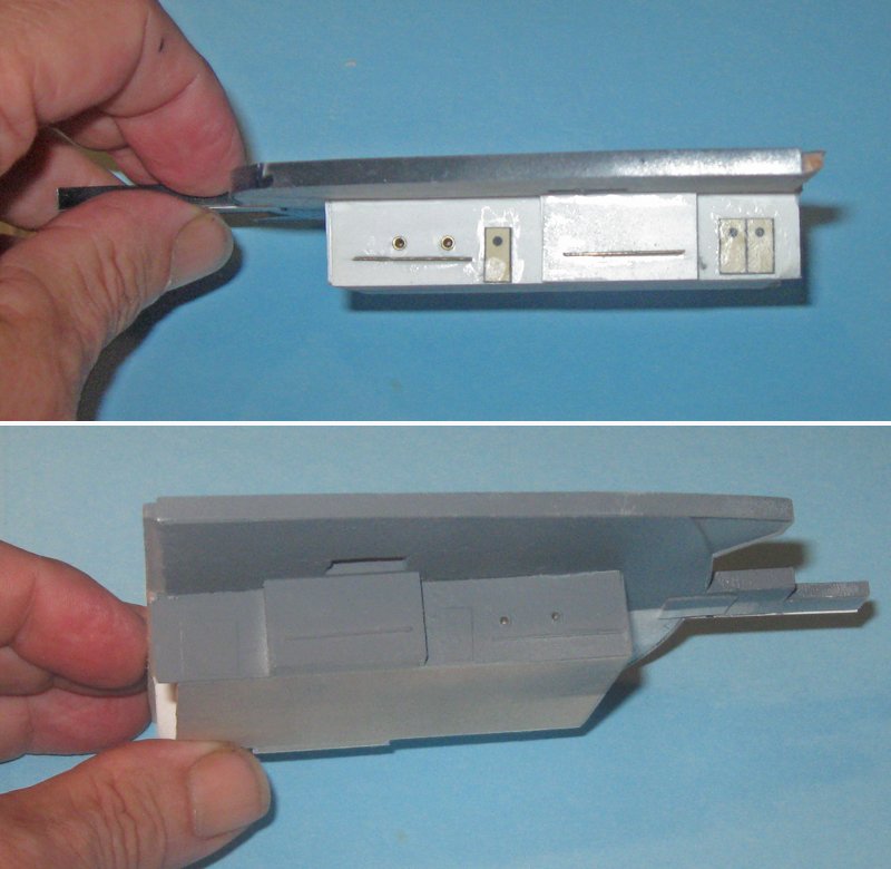
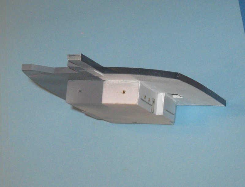
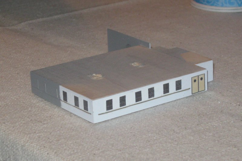
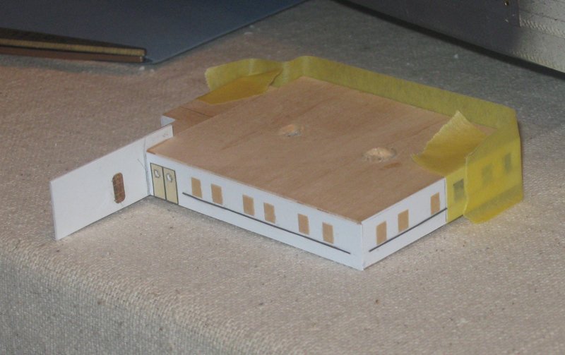
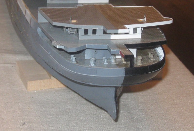
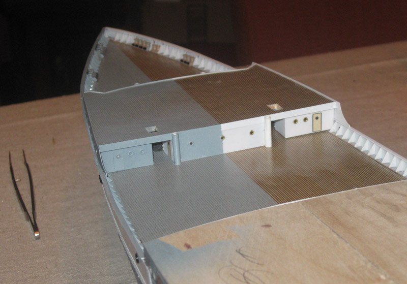
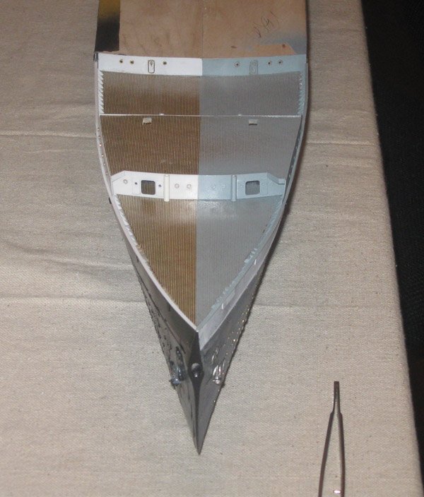
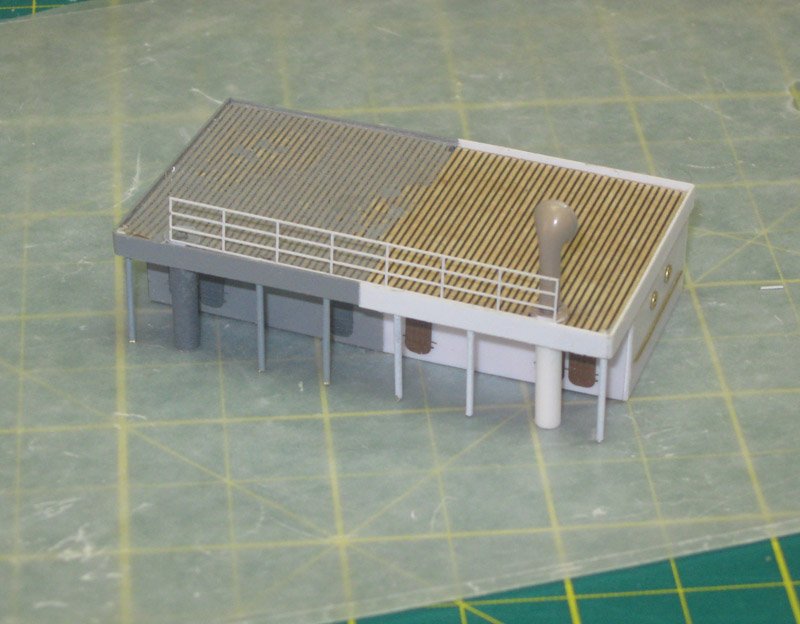
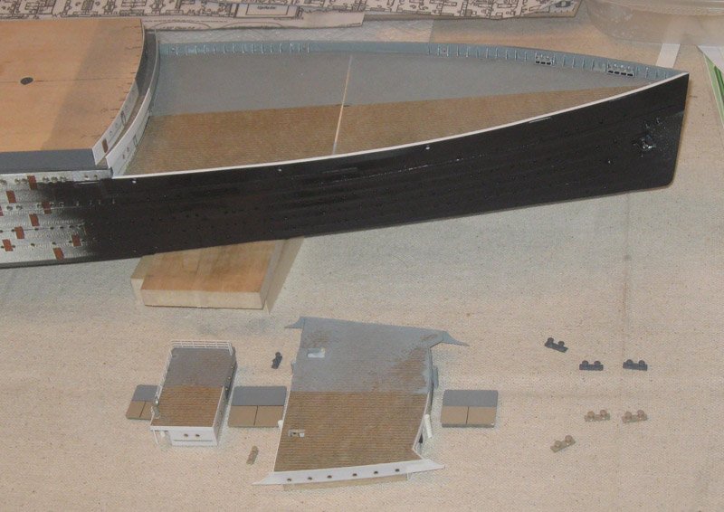
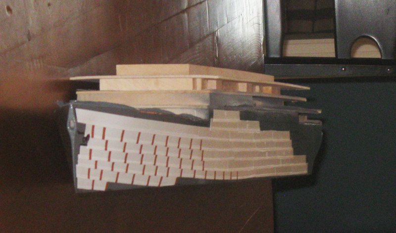
Hello again to all - And thanks for the likes, compliments, and most especially for the suggestions. The more the better. A professor of mine once said that there was never an 'A' student who was smarter than 3 'C' students. So students like me need all the help we can get. I left the last segment with the bow ready for deck fittings, then I turned my attention to the stern. With ocean liners, which are built somewhat along the lines of a wedding cake, I find that I retain the most flexibility by building in from the ends before moving up in the middle. Here at the stern there is a three layer cake consisting of, first, the working deck at E level, its deck house pierced by small portholes and several doors. The middle layer is the aft end of D deck with a narrow extension reaching to the aft rail where the flagstaff is located. This deck house is more open, with large rectangular windows. The upper deck at C level is open to the sky and does not connect to the rest of C deck. It holds various boats, davits, vents, etc., as well as having a small rounded platform for the mooring lookout. Its deck house is small and square and has a dark wooden surface, possibly mahogany. During the war some significant changes were made to these decks. On D deck a platform was built out and aft to hold the stern 6 inch gun. To improve its field of fire the ensign flagstaff platform extension was shortened. To reduce damage from the blast shock the overhanging piece of C deck was cut back. Then everything, including the decoration below the counter, was painted grey. Taking the shapes of the decks and deck houses from the plans for both the liner and troop ship configurations, and as confirmed by examining the photographs, these deck units were built up. You can see the lack of symmetry in this photo, which is the whole point of the model, I guess. They were built up in my usual way, with sheathed ½” basswood plank for the house, topped with 3/32” basswood sheet, edged in 1/8” styrene which gives a little lip to the deck edge for the railings to come. The underside of the deck was painted white on the liner side and grey on the troop ship side. The portholes are the smaller brass grommets, the doors are printed appliques of sturdy art paper, the handrails are wire. I thought that the textural contrasts would be enough to set off the details on the troop ship side, but it is clear that they simply disappear into the background. This may have worked during wartime, but for modelling purposes, I thought that they should stand out much more. Here on the D deck house I made the large rectangular windows by creating and printing them out in black on white carrier film. The liner side was masked before I added the details to the troop ship side. This time I cut the windows from art paper that was a bit thicker, hoping that this would give sufficient contrast. However, as you can see after stacking the deck units in place, the troop ship side was a visually flat grey. The solution turned out to be pretty simple, and I should have hit on it sooner. I just printed the black windows onto clear decal film, then set them in place. They are probably more visible than is historically accurate, but without magnification and direct lighting they do not jump out too much. Note here the first use of red to denote a structural change on the area where the ensign platform has been cut back. The site is telling me that I want to put in too many photos for one posting, so I will break it into two at this point. Dan

- 238 replies
-
- 12
-
-
- leviathan
- troop ship
- (and 2 more)
-
Hi Guys - Thanks for the compliments. It is a strange critter, and will be getting stranger. Druxey - that is one of the techniques that I will be experimenting with. There are usually 6 good ways to get any modeling task accomplished, and I will have to find the one that works for me. But the masts have lookout platforms, various fittings and mast bands, etc. which would also have to be made in two halves. It may just be easier to use a combination of careful masking and brush painting. We will have to see. Dan
- 238 replies
-
- 6
-
-
- leviathan
- troop ship
- (and 2 more)
-
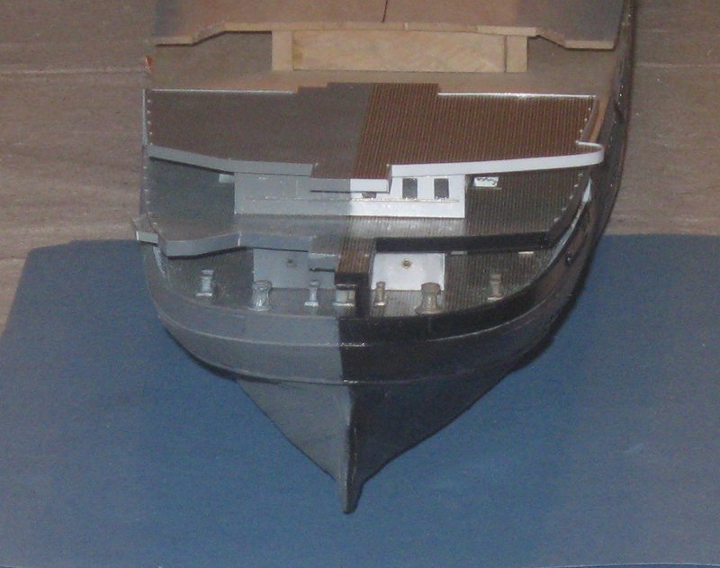
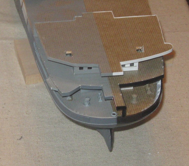
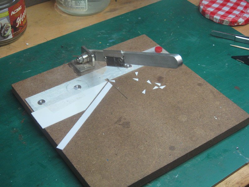
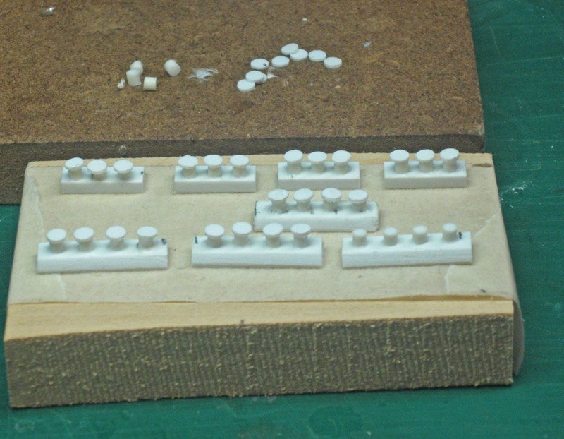
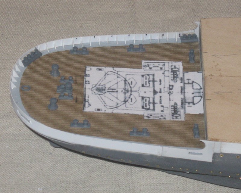
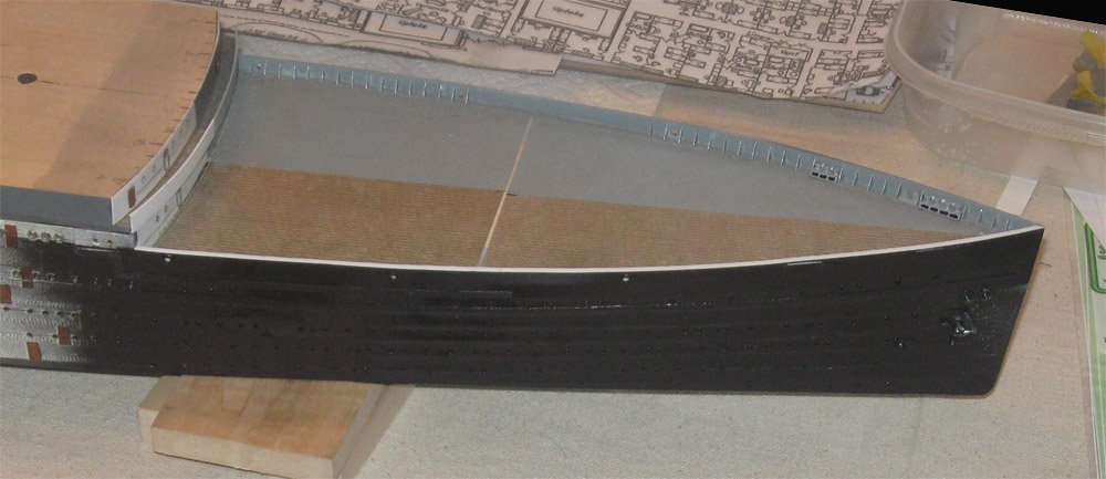
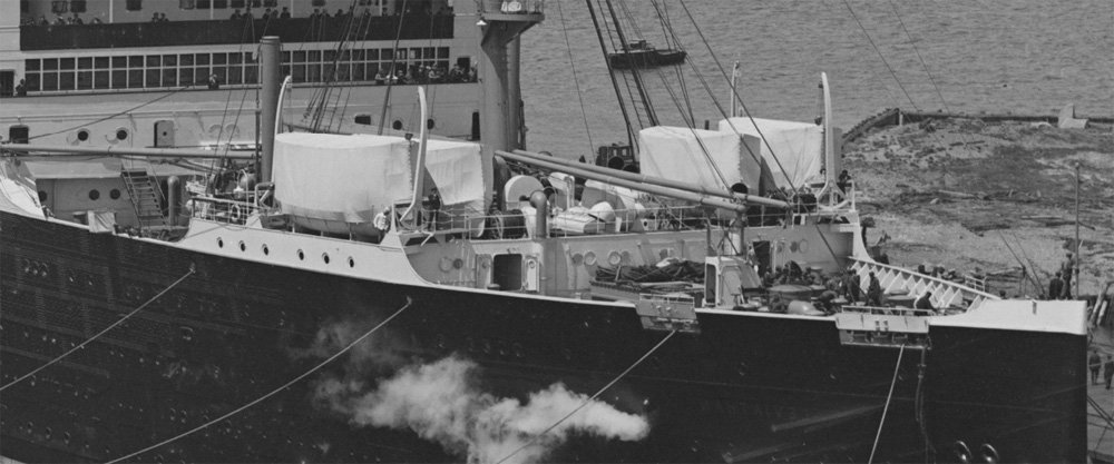
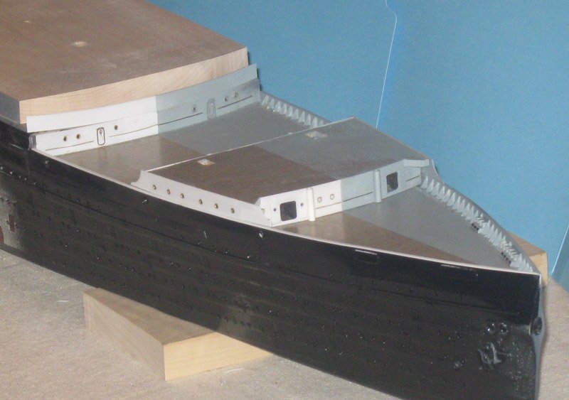
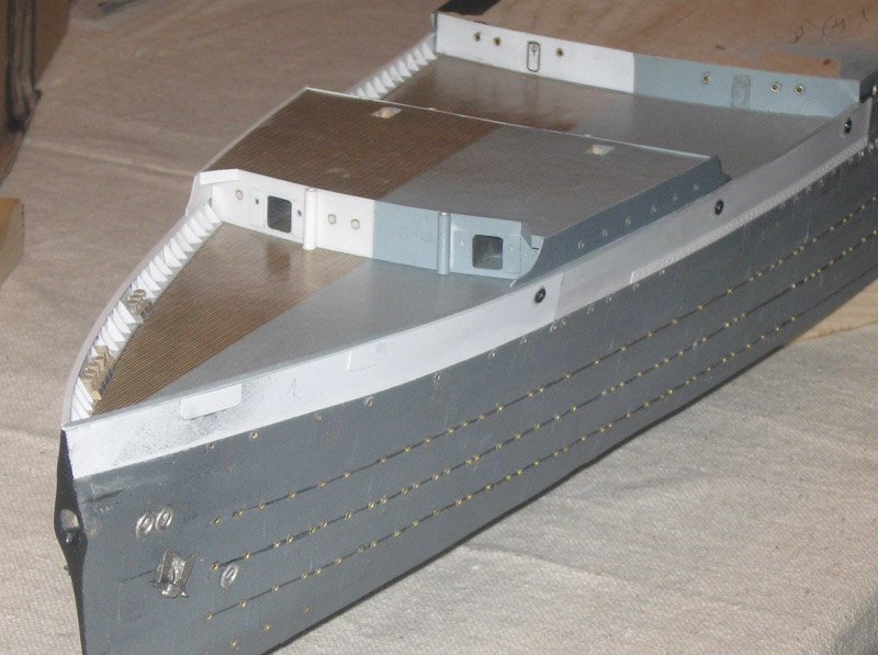
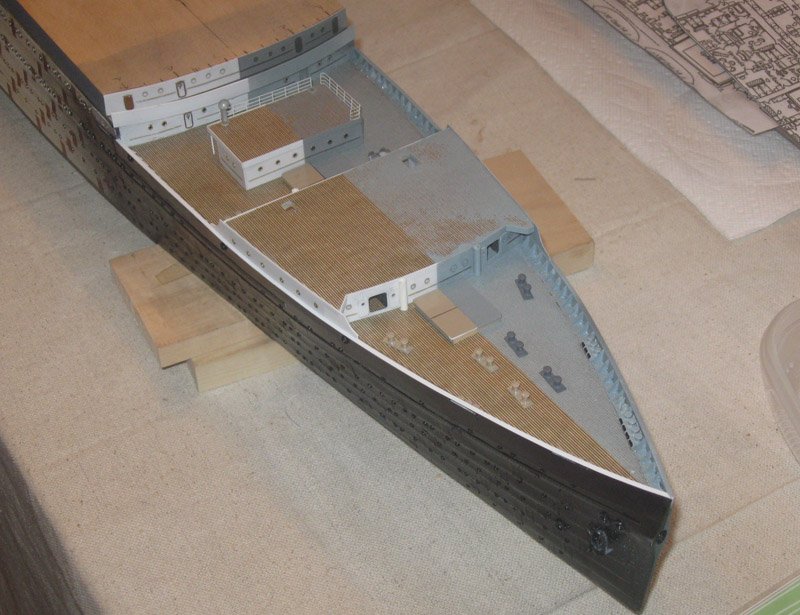
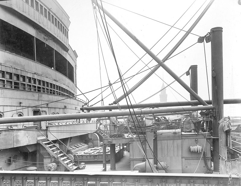
Hello again, and thanks for looking in. Construction continued with the sheer strakes which incorporated the bulwarks of the working decks at the bow and stern. They are at different levels, with the bow being part of D Deck, while the stern is at the E Deck level. For the bow I took wider strips of styrene which were 0.015” thick. I thought I needed the extra thickness for structural strength above the support of the hull block. The lower edge of the new strip was fitted to the upper edge of the prior plates and parallel with the top line of portholes, then it was taped in place. Using a compass I marked the inside with a line setting a consistent height of 4 feet (1/4”) for the bulwarks. The strips were removed and shaped to the line. I located and drilled three round holes for the hawser leads and two slots for the fairleads, although these were hidden by solid hinged doors such as the one that can be seen just aft of the bow. At the stern the strakes around the compound curves had to be built up one at a time, then faired into a final vertical bulwark. I made and discarded several sets of paper patterns before getting it to match the photographs. Here I did my first significant split painting. I sprayed dark grey primer on both sides of the hull with the inside of the stbd bulwark masked to keep it white. Then I masked the port side and painted the stbd side black. I got some underspray but I decanted some of the primer and cleaned it up with a brush. The deck is also split. Many of the photos of the troop ship have decks that look a lot like they match the grey of the deck houses and bulwarks, so we decided they should look it on the model. It also gives a stark contrast between the two representations. To keep the lines of the deck planks visible I misted the paint from a distance to make a translucent layer. This deck is a test piece and was ultimately replaced. My guide for the bulwarks was this photo of the troop ship. The wood deck ends several feet from the bulwark, leaving a gutter space for the triangular supports for the bulwark. Also in that space are two four-post fairleads near the bow and two three-post ones further aft near the chain winches. A fairly wide caprail tops the bulwarks with a small breakwater mounted on top at the bow. The supports were chopped from a ¼” strip using an inexpensive commercial device I bought a while ago. It has served faithfully as long as I replace the blade frequently. The fairleads were built up by taking thick strip ¼” wide, cutting pieces to length and sanding a bevel into the inner edge. Short posts were cut from solid rod as carefully as I could. Using the squarest ends they were glued to the bases with white glue which gave me some time for adjustments as it set. When the glue was dry the posts were all reinforced with CA. When everything was sturdy I lightly sanded to tops of the posts level and even. Then they were topped by small discs punched out of a sheet with a leather-working punch. The fairleads were primed dark grey, as were a number of bollards and winches that started life as Bluejacket castings. They were set in place to help locate the fairleads exactly. The fairleads then located the bulwark supports and the spacing between them. This then determined the locations of the stanchions which support the next deck, and they are marked in black. Everything was removed and the bulwarks, supports and perimeters were given contrasting colors. I decided on a dark grey for the port side to match the primer on the fittings. A better deck was made, a margin plank applied, and the port side misted grey before being glued down. Another test. The port side fittings are a light grey, the stbd ones are buff colored, as seen in a few photos. The buff ones are good, but on the port side I did not like the contrast between the light fittings and dark bulwarks. At the bow I made the fairleads and bulwarks the same light grey. I like the look better, and it is closer to what I see in the photos. I will probably do some dark washes at the end of the build to bring out a bit of contrast. Now I could mask the interior of the bulwark and paint the liner side gloss black to a point just past the end of the working deck. The stbd caprail had been left off until now to keep it pristine white, and now it was attached, making a very clean color separation line. In the middle of this area is a large deckhouse spanning the full width of the deck. Side panels sit on top of the caprails and curve into them. A number of portholes pierce all sides of the house, with two wide corridors running through the house, which could be closed off with double steel watertight doors on the forward face. The forward mast, several boats and davits, winches and ventilators cover its roof, but those details are for much later. The deckhouse is built up from a ½” basswood for the body of the house, with a 3/32” roof. It is sheathed in styrene which extends just a bit above the roof. This lip will anchor the brass railings that will go on later. Portholes on the sides were installed as before, but I left the ones on the liner side bright brass. On the forward face I cut two large doorways with rounded corners and flanked them with doors made from strip. The portholes on this face are PE from Tom’s Modelworks, Nice, but ultimately I did not like them. It was a question of visibility. They just did not stand out well enough. Handrails on the liner side are bright brass wire. On the liner side, soft iron wire. This is the basic pattern that all future deckhouses will follow. From the opposite angle you see that the PE portholes on the troop ship side have disappeared completely. The portholes on the face of the main deckhouse are much more visible and match those on the hull. The aft side of the deckhouse has the same corridor openings, but without the watertight doors. The round pillars are bases for tall, thin horn ventilators. The roof has been pierced for staircases, cut small to be expanded later. All along I have been taking test photos to judge my progress. Here is one to check the symmetry of the hull and the details. If you have a sharp eye, you will notice that the small triangular roof extension at the forward corner of the deckhouse is smaller for the liner than for the troop ship. This is just the first of many subtle and not so subtle differences from one to the other. The same techniques were used to build up the small, but detailed, 4th Class entryway which fits on deck between the deckhouse and the superstructure. Some more detailing is needed, but it will help locate stairways, cargo cranes, and other fittings. Here are some of those details for the bow deck, including three hatches and a number of bollards. And here they are set in approximate place. Now, as I write this, I can see that the entryway that I spent a good bit of time on is too big. It crowds the hatches and will get in the way of future fittings, including a gun platform on the troop ship. I will have to make up another one. But not now. Be well Dan
- 238 replies
-
- 22
-
-
- leviathan
- troop ship
- (and 2 more)
-
Hi y'all - Sorry, that's some of the Texas twang I picked up from Mitch, who did a great job as MC of the conference. A tip of the hat to him. Although it was not too well attended, the talks were an interesting mix of high-level technique demonstrations and some underwater archaeology and conservation studies and methods. The after dinner speaker was excellent. There are lots of photos of the models in the NRG News section on the MSW home page. Thanks for the compliments on the rivet technique. I know that it can be improved, but it worked for me. Phil - glad to have you along. Let me know how the brass works out. I did not add any additional glue to the copper, but am not relying on it completely. By the time the model is done the strips will have been sealed with multiple coats of primer, paint and finishes. I do use thin CA under any corners that might get lifted during later construction. J - thanks for the link. I had seen it before, but I had to upgrade my computer to get the most detail out of the photos. I will be using them a lot. Dan
- 238 replies
-
- 3
-
-
- leviathan
- troop ship
- (and 2 more)
-
How was the 2018 Conference?
shipmodel replied to VinceMcCullough's topic in NAUTICAL RESEARCH GUILD - News & Information
Thanks to the Board for putting together a top shelf conference, and especially to Mitch for being such a genial and humorous host. Till next year in New Bedford ? Dan -
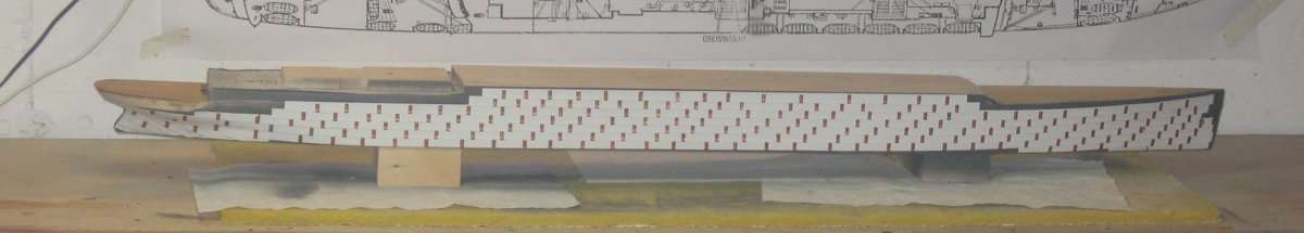
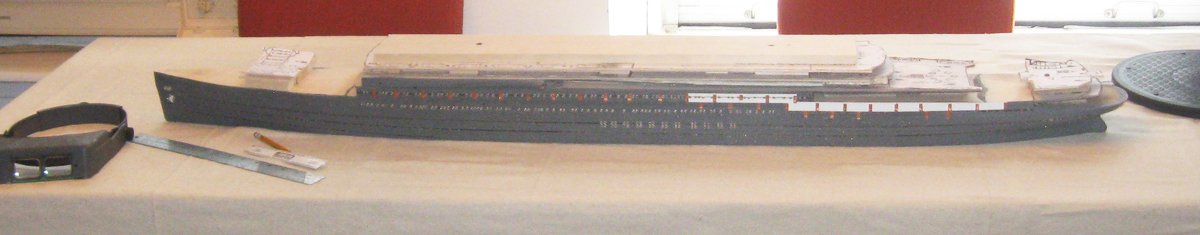
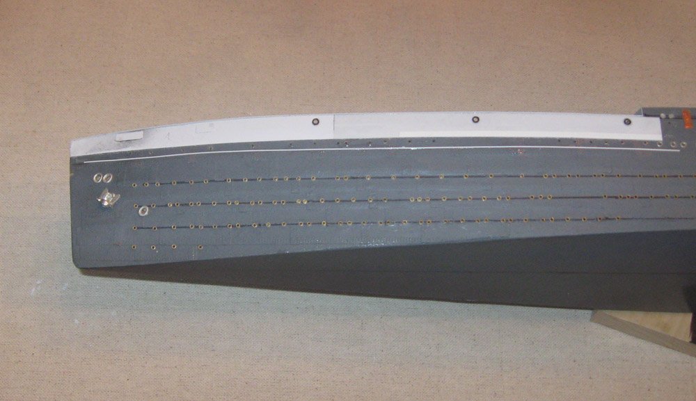
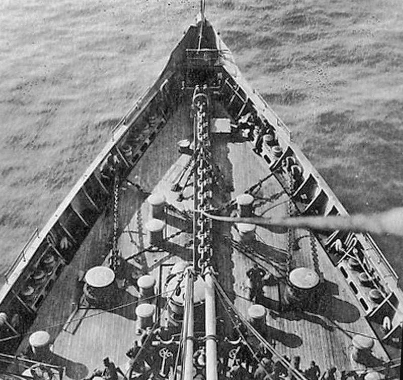
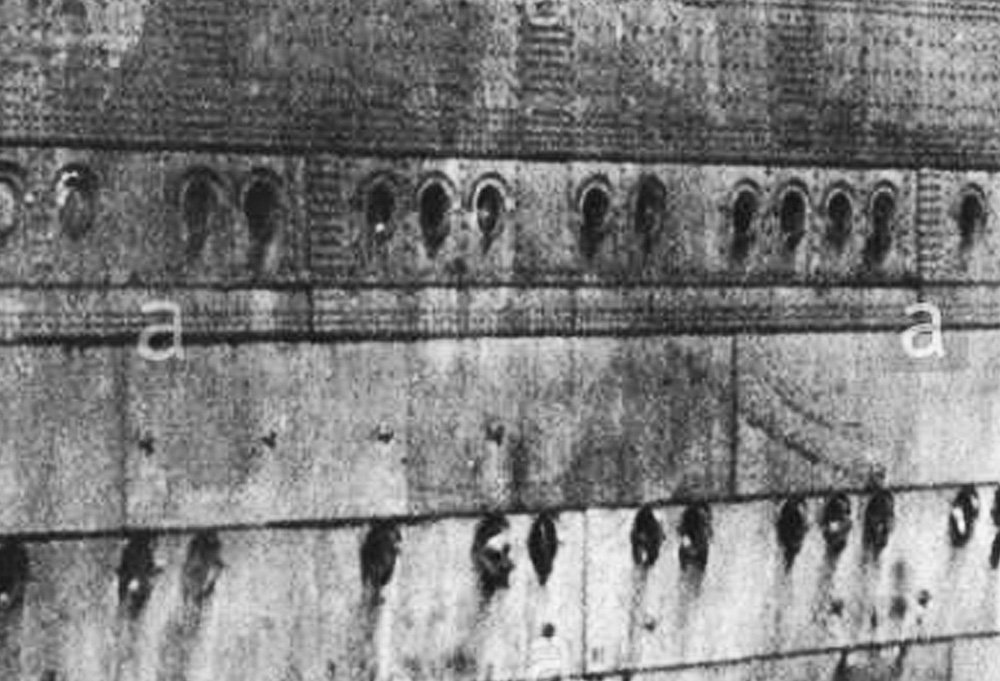
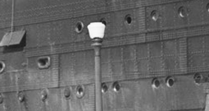
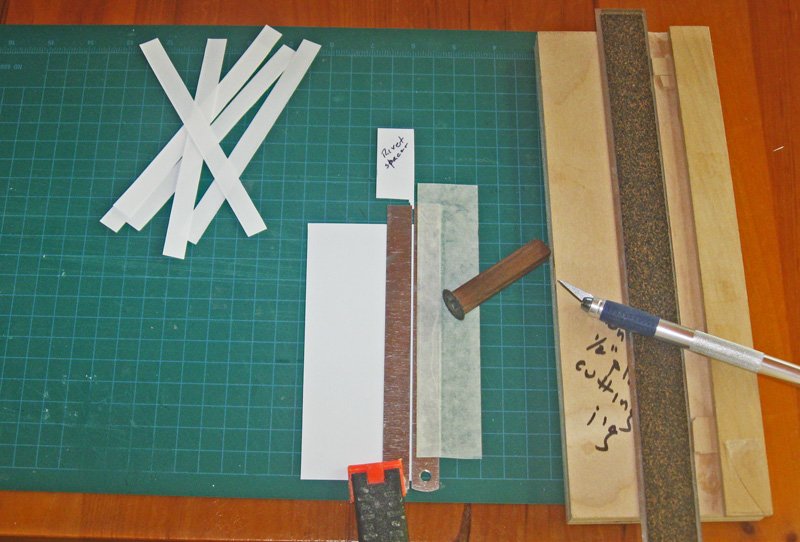
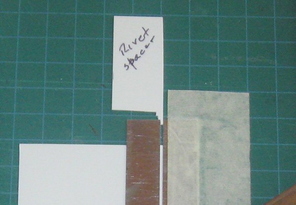
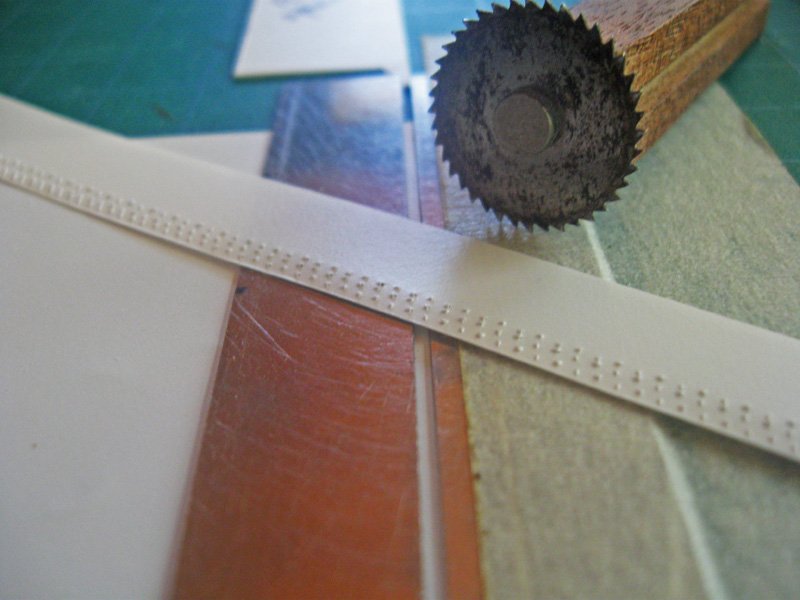
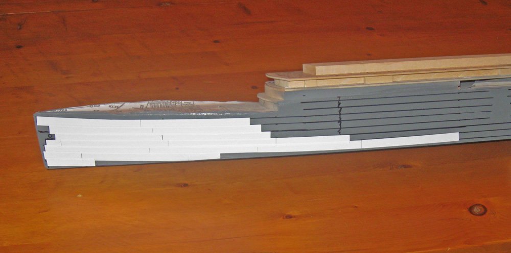
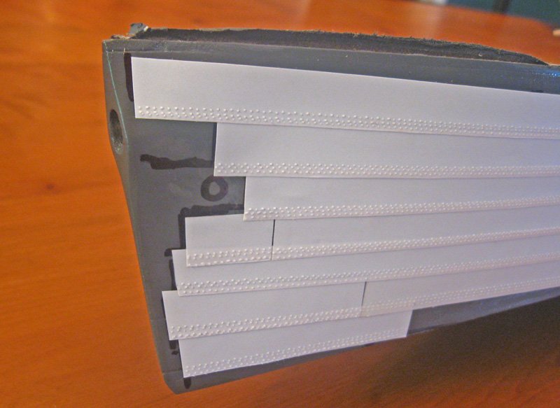
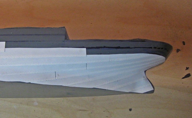
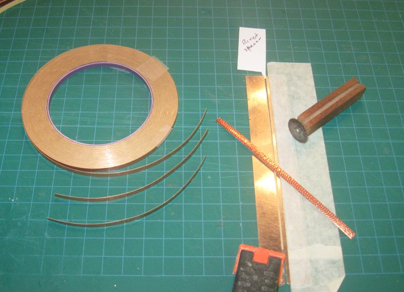
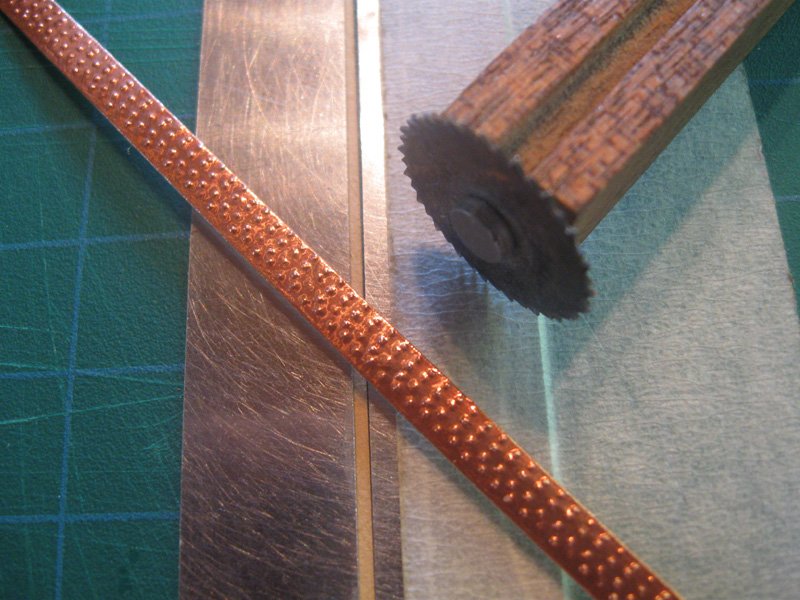
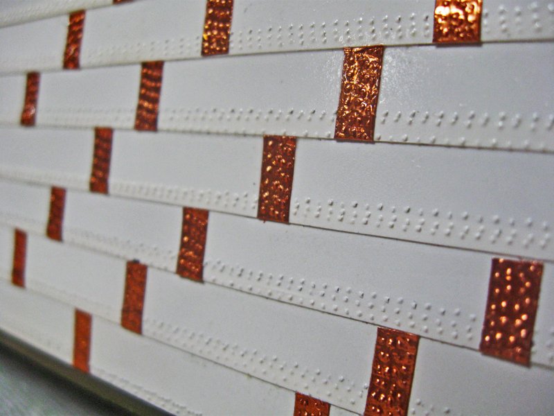
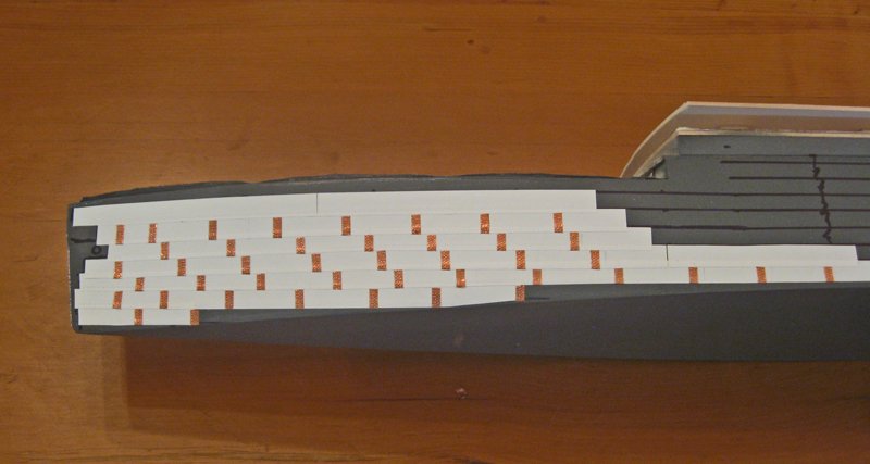
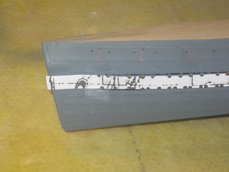
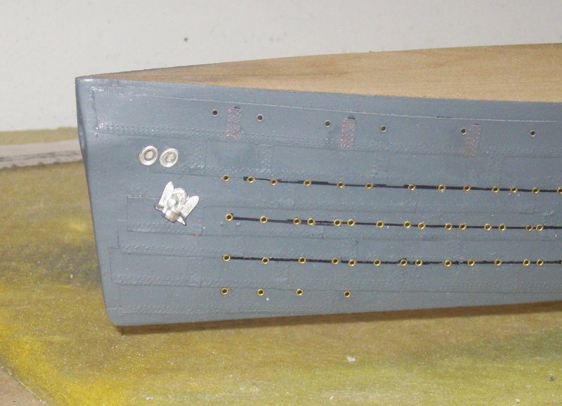
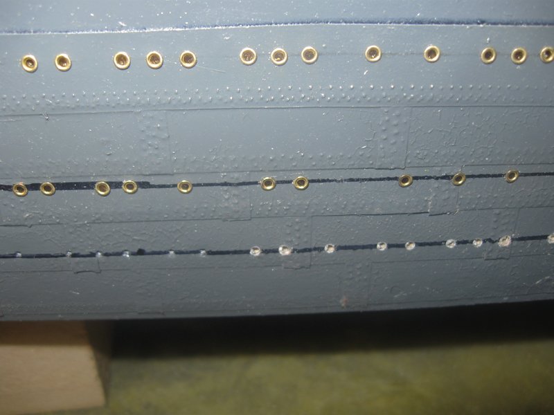
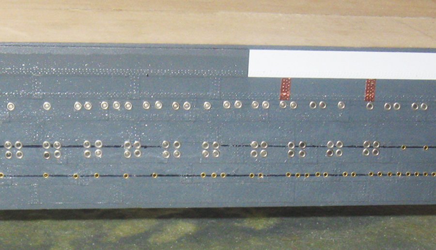
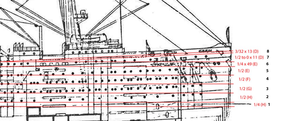
Hello again all. Here is the next segment, posted quickly since I will be leaving for the NRG conference in Las Vegas tomorrow morning. Hope to see some of you there. Now that the hull block has been shaped and primed, I had to decide how detailed I wanted to make its surface. From a distance – even by modeling standards – the liner hull is a fairly undifferentiated black. The troop ship hull is a riot of colors and shapes. In both cases I believe that I could have left the surface fairly clean without compromising the educational value of the model to the museum. However, that is not my way, as anyone who knows my mania will tell you. The hull was built up out of steel plates that appear to be about 8 feet tall and 25 feet long. The upper strakes overlap the lower ones, so there is a step up with each successive plate from the hull to the sheer. Judging from the shadows that they cast, the plates appear to be about 1 inch thick. These plates were attached with rows of rivets along their bottom edges and through the overlapped plates of the strake below. They were secured to each other along the same strake with narrow vertical connector plates that covered the joints and were riveted to both plates. I resolved to replicate this look as best I could. Extra-high resolution photos showed that the plates were also secured with a number of lines of rivets in the middle of the plates. This was a step too far for me, but perhaps I will attempt it if I do another hull where I have more building time. I started with 0.005” styrene sheet, which scales out to 1 inch thick. The sheet was cut to 6 inches wide, which scales out to 100 feet, or 4 full sized plates. To make the lines of rivets I butted the edge of the sheet against a straight metal rule which had been taped down to a cutting mat. A second rule was placed on top of the sheet and adjusted so it was parallel with the first, then it was clamped in place. The shaft of a Dremel circular saw bitt was slipped into a hole in a piece of scrapwood so it could spin, then rolled along against the edge of the top rule. This left a line of indentations pushed down into the soft cutting mat. The top rule was moved out and a second line of indentation was made, then a third. Then the sheet was placed in a wooden cutting jig and a ½” strip parted off with the triple line of rivets along one edge. To keep the lines of rivets consistently spaced from each other, and from strip to strip, I made up a quick rivet spacer with three steps. The end result was a plating strip with three parallel rows of bumps that were close enough in scale to approximate the real rivets. These strips were applied to the hull block from the waterline up, following a series of drawn lines that matched the lines of plating strakes seen in the photographs. At the bow they ended before the edge of the stem. In the photos these areas do not have rivets and look to have been welded. The drawn circle is the future location for the housed anchor. At the stern the strakes fair upwards and taper slightly to cover the complex curves and to match other photos. The connector plates were made from ¼” wide self-adhesive copper foil on a paper backing. This is available from any stained glass supply company in every width up to a full half inch in 1/32 inch increments, so the right one can be found whatever scale you are working in. A 5 inch length was cut off the roll and 4 lines of rivets impressed from the back through the paper and into the mat. Short lengths of the riveted foil were cut off and applied to the plating strips. They covered each joint between strips and then in a staggered pattern to define the individual plates. Some of the copper plates had to be adjusted forward or aft, but I could set up a pretty regular pattern that never had one joint directly above another. The developing pattern clearly defines the curved sheer of the ship. I left the uppermost strake off at this point because the final strake will be thicker and will incorporate the solid bulwark around the open deck. Here is the starboard side for the liner with all the plates and connectors applied. The port side was done the same way. Without counting precisely, I estimate that there are over 200,000 “rivets” on the model. The port side was sealed with another coat of dark grey primer and the lines of portholes located according to the photos and plans. These were drawn on the hull and adjusted as needed to make smooth, fair curves that matched the plating strakes. Then the “porthole plan” from Cutting Plan 1 was cut along the line of one row of portholes and taped to the hull so I could get the location of each porthole. Here you can see the process in one view, from the bottom up. 1) the lines were drawn; 2) a small nail was used to make dimples at each porthole location; 3) a hole was drilled at each dimple that was deep enough to accept the shaft of a small brass grommet; 4) the holes were painted with white glue and the grommets slipped in; 5) any grommets that were out of line were corrected and they were all tapped down flush. At the bow you can see how the lines of portholes relate to each other and to the stowed anchor and a pair of auxiliary hawse holes. In the midships area there are two sizes of portholes, some of which are set in a square pattern of four. By actual count there are more than 2,500 portholes on the model. Inserting them individually into their proper holes aggravated a carpal tunnel-like problem that I get, which my doctor calls “porthole thumb”. It requires a somewhat painful cortisone injection to the base of my right thumb, but it does clear up. So here is the troop ship port side with all of its portholes set up almost to the sheer. After the starboard liner side was done the hull was basically complete, and I turned to some of the detail work on the bow and stern working decks. I will post that when I get back from Vegas. Till then, be well. Dan
- 238 replies
-
- 20
-
-
- leviathan
- troop ship
- (and 2 more)
-
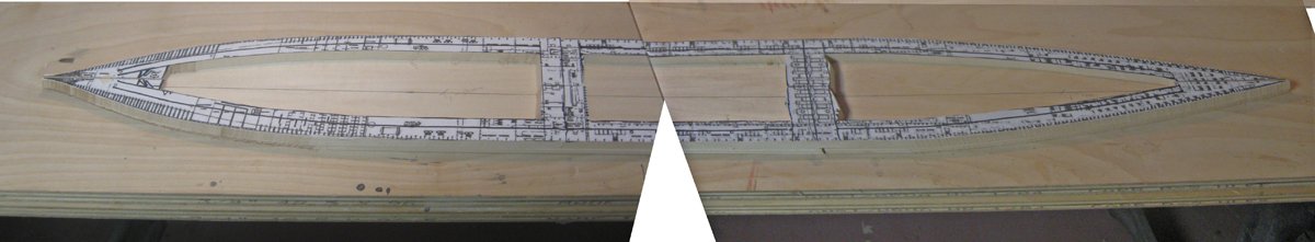
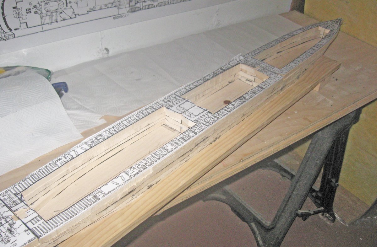
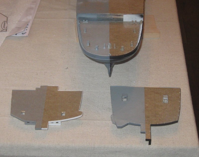
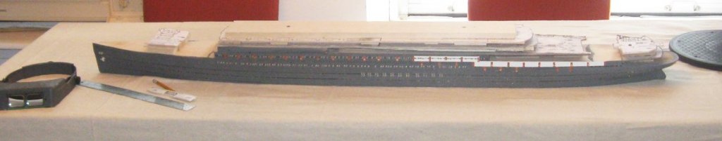
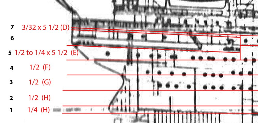
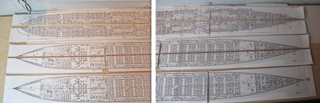
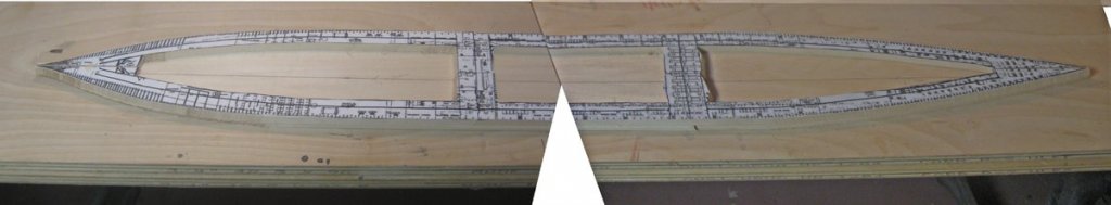
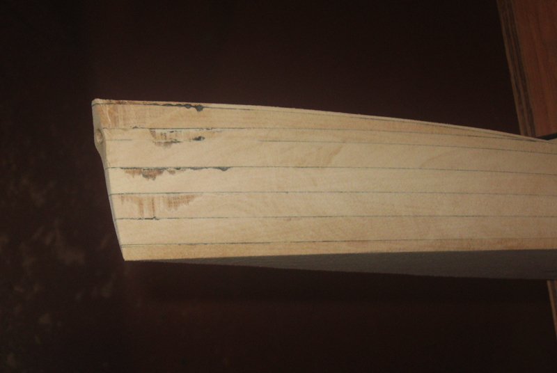
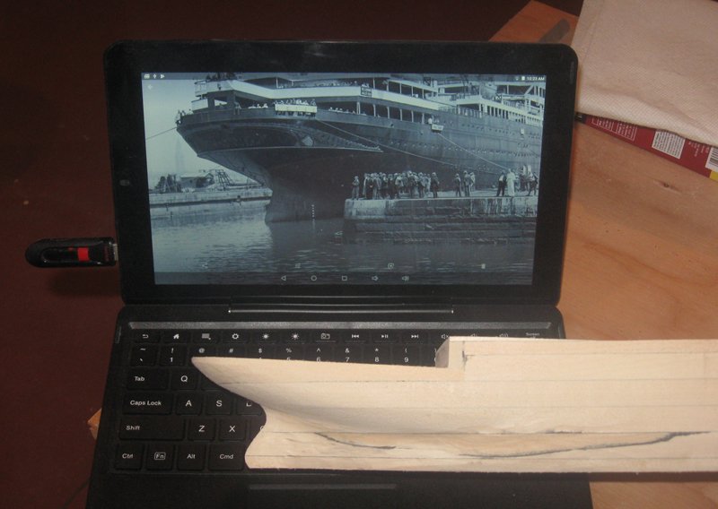
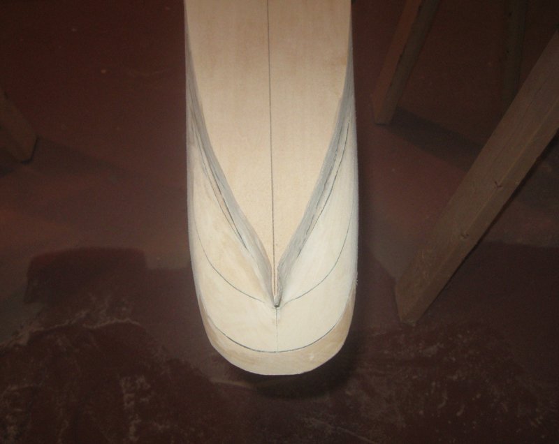
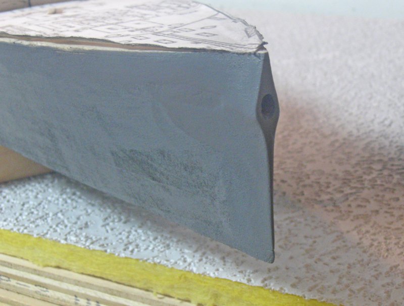
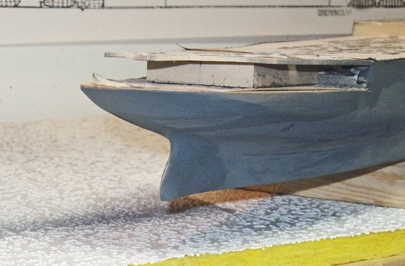
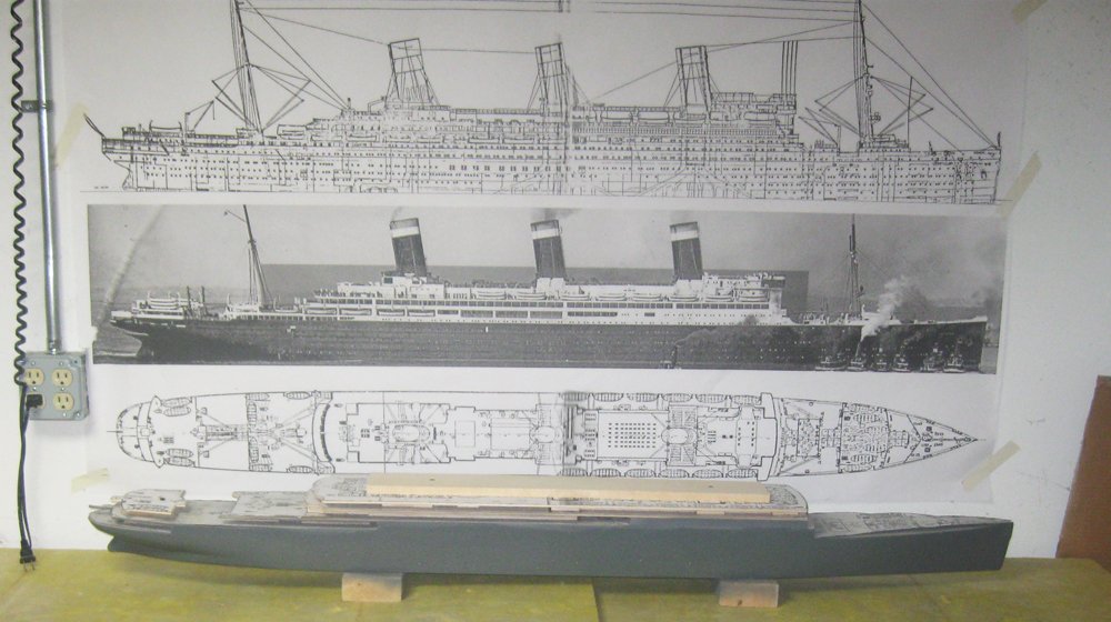
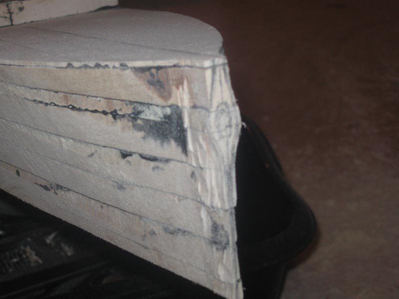
Hello again and welcome to the next segment of the build. In this one the hull block will be roughed out. First, to determine what wood to order, I laid out the lifts. Taking the profile view I adjusted it until it was exactly level, then drew in horizontal lines to divide the hull from the waterline up to the level of the working deck at the bow – D deck. I started with a ¼” lift at the waterline and just below. This will later be attached to the building board which will become the base for the ocean. Four ½ inch lifts follow. Each lift is labeled to show its thickness and the deck plan that will be used to rough cut each to the outline of the hull. Above the fifth lift is another ¼” lift and then two upper layers that are tapered to account for the rise of the sheer at the bow. At the stern the lifts are similar, although the open working deck here is one level down, at the level of E deck. There is a similar taper in a lift for the sheer. The model was going to be just under 5 feet long, but basswood only comes in lengths of 2,3,4, and 6 feet. I could have ordered 6 foot planks, but they are significantly more expensive and there would be a good deal of waste. Instead, I pieced the hull together by alternating 2 and 3 foot lengths, staggering the joints from layer to layer. I also only ordered a few pieces in the full 6 inch breadth of the model. The rest were 3 inches wide and would be joined together in the construction process. The plans for each lift were cut from the printed sheets and laid out on the wood. A spray photo mount glue was used so they could be easily removed later. For each lift the wood pieces were clamped together without glue and the plans were attached. While still clamped in place the paper was cut along the joints. Here are the first three lifts laid out in a somewhat confusing composite photo. Hope you can understand it well enough. The lifts were cut out along the perimeter of the plans, leaving them a bit oversize for later shaping. The base waterline lift was left intact, but above that the lifts were hollowed by removing most of the interior wood. I do this so that wood movement is minimized and the stresses have some where to go other than deforming the exterior shape. Using the narrow planks meant that I had open access to the middle of the lift, so I could remove the wood with my band saw and did not have to drill, chisel, or rout it out. Two bridges were left at the 2 and 3 foot positions along the lift for structural strength. Here is the waterline lift with the next lift above it. Each lift was glued to the one below with woodworkers’ yellow glue that was colored black with a few drops of acrylic paint. They were individually clamped and secured, making sure that each was exactly on the centerline. Here I have built them up to the last fully horizontal lift, which is also the last one that was hollowed. I glued a penny to the center of the ship for luck. The tapering lifts were cut to shape and planed to the proper profile. When all were set a power sander was used to shape the hull. Here at the bow you can see that tapered lift. Using the black glue always gives me reference lines, no matter how much wood is removed. At the stern the shaping was a bit more complex. I did not have any cross-sections for this area from the plans, just the stern profile. I used the photographs to refine the shape, setting them up on my laptop so I could look at them as I worked. Even with all my planning I found that the first thick lift was too narrow in one spot, so a strip of wood was glued in and shaped to fill the gap. Using the black glue also let me see the symmetry of the hull as it was being shaped, especially at the stern. There is still a bit more refining to do in this shot, but it is getting close. The issue at the bow is that Leviathan carried not only the usual two anchors on the sides of the ship, but a third larger anchor which ran out from the nose of the ship. This meant that the bow flared out in a long diamond shape so there was room for the hawse hole. This is a detail that cannot be seen on any of the plans, but only on the various photographs. The location of the hole was carefully drawn on with the oval shape that the angled hawse pipe makes, and then carved into the excess wood that had been left at the bow. The black glue that secured the narrow lift pieces together established an indelible centerline that I used to guide the shaping of the bow. When the basic shaping was done I gave the hull a first coat of primer to show me where I needed more fairing and smoothing, some of which you can see. Where I was satisfied with the shape the wood was given a coat of Minwax wood hardener. I like this product because it dries quite hard and protects the cut and shaped edges from dings and nicks. I only use it where I am very close to final shape because it is a bear to try to sand after it has set. You can see from the darkened areas that I have only used it at this point on the edges of the hull block and the thin area above the rudder. The hull block was built up in this way up to D deck plus the forward portion of the deckhouse of C deck. Although I cut out the shapes of the decks and deck houses up to A deck, they were left rough but stacked in place to give me an idea of future work to do. So here is the model at this point in front of the triple image. Next time, plating, rivets, and portholes. Be well Dan

- 238 replies
-
- 23
-
-
- leviathan
- troop ship
- (and 2 more)
-
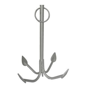
Hi Chuck - Beautiful work, as always. Those rudder gudgeons and pintles are a great solution to a tricky problem. I hate to pick a nit, but I don't like the grapnel. Judging by the shape of the laser cut pieces, the flukes on your grapnel arms are set perpendicular to the shaft, making the points stick straight out, rather than pointing up toward the top of the shaft. Here is a photo of a modern grapnel. Other illustrations confirm the alignment. If you think about how the grapnel works, you can see how having flukes that stick out would actually get in the way of the point biting in and holding. I'm sure you can change this with a little adjustment of the ends of the arms. Looking forward to watching the group build. Dan
- 421 replies
-
- 6
-
-
- medway longboat
- Syren Ship Model Company
- (and 1 more)
-
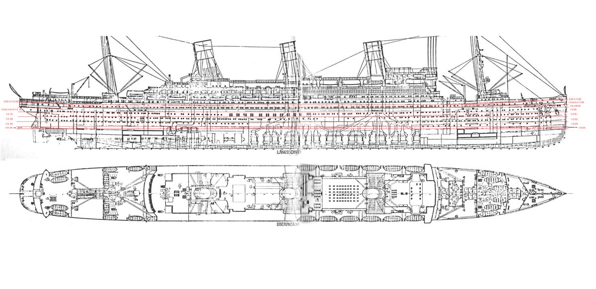
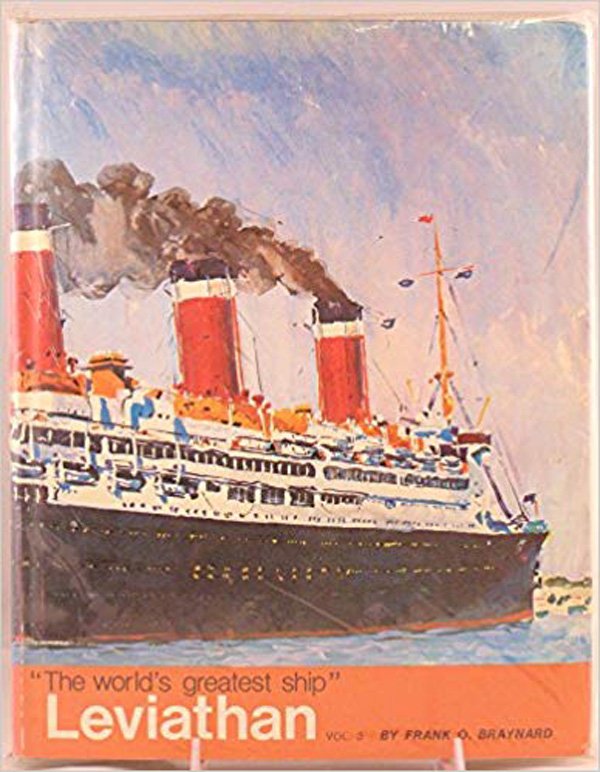
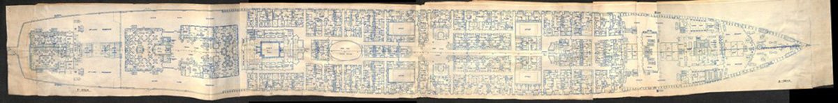
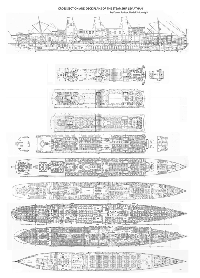
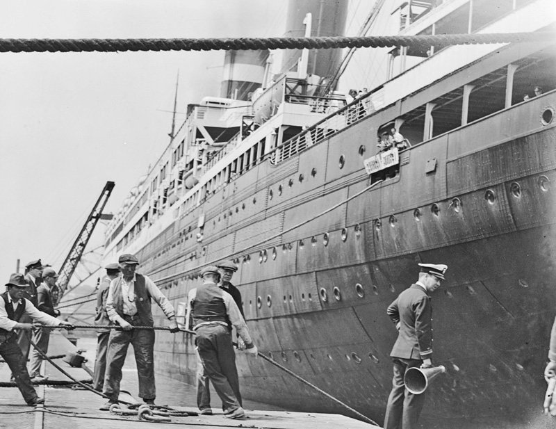
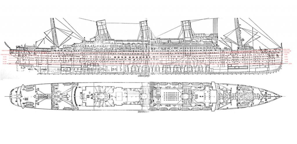
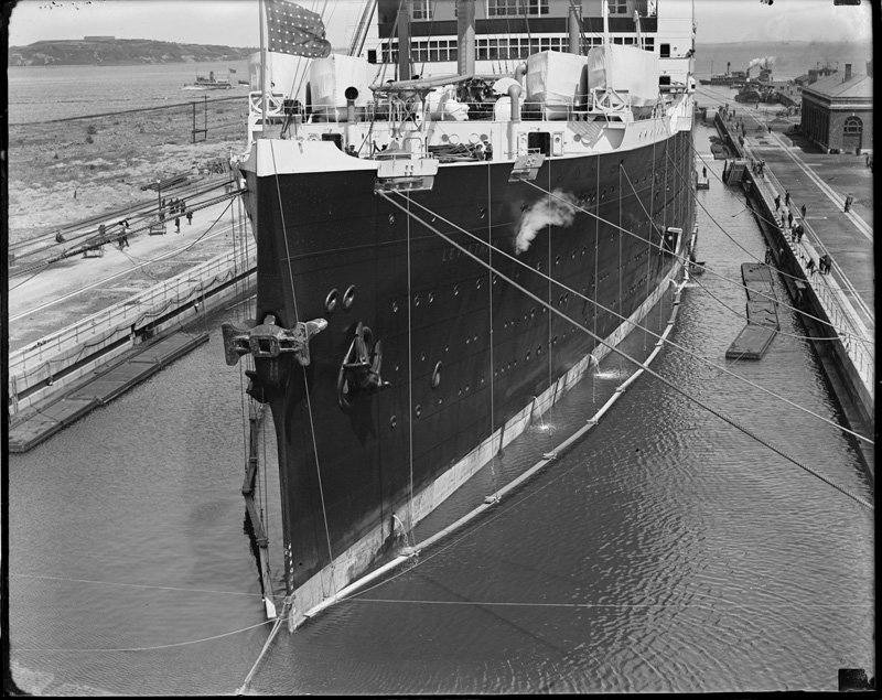
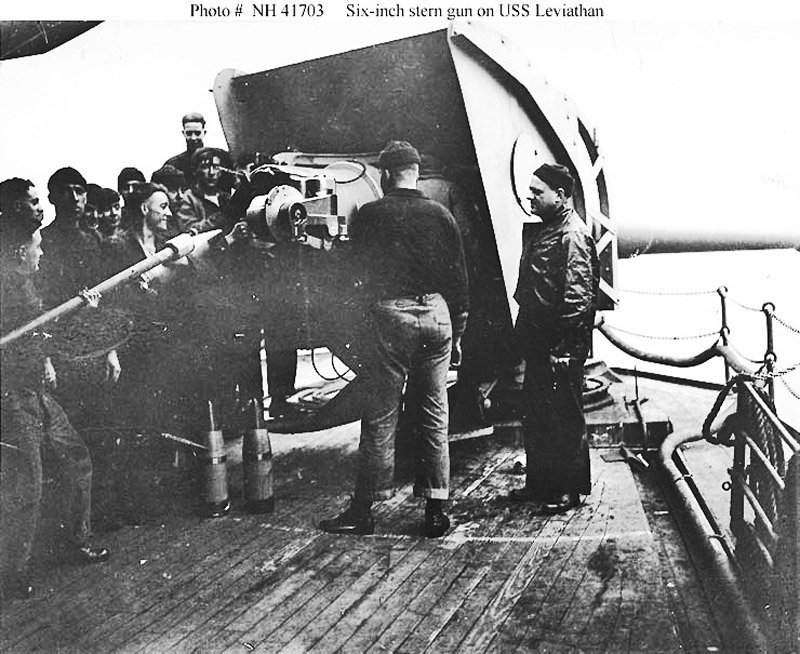
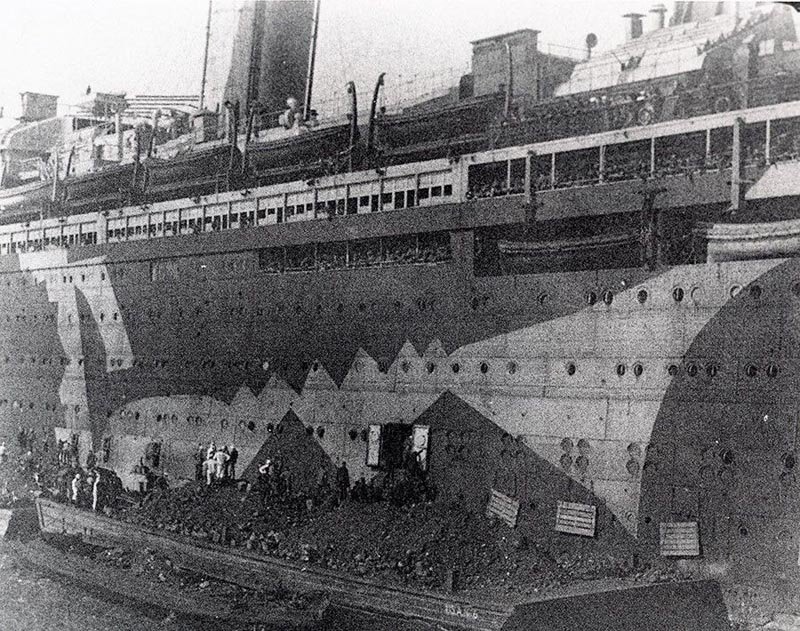
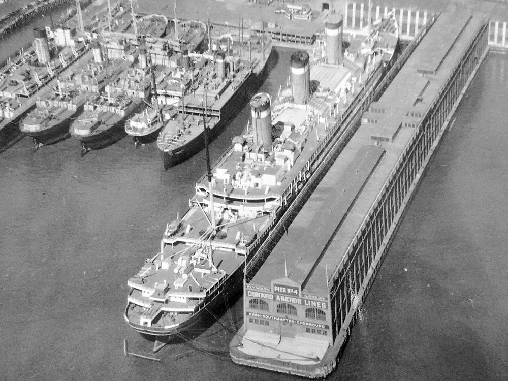
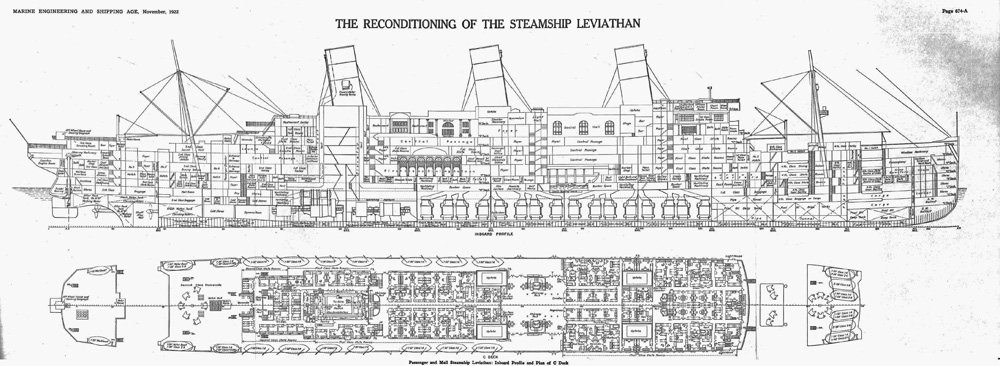
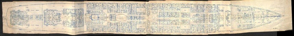
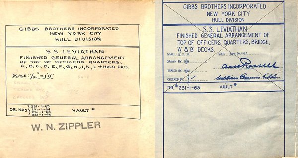
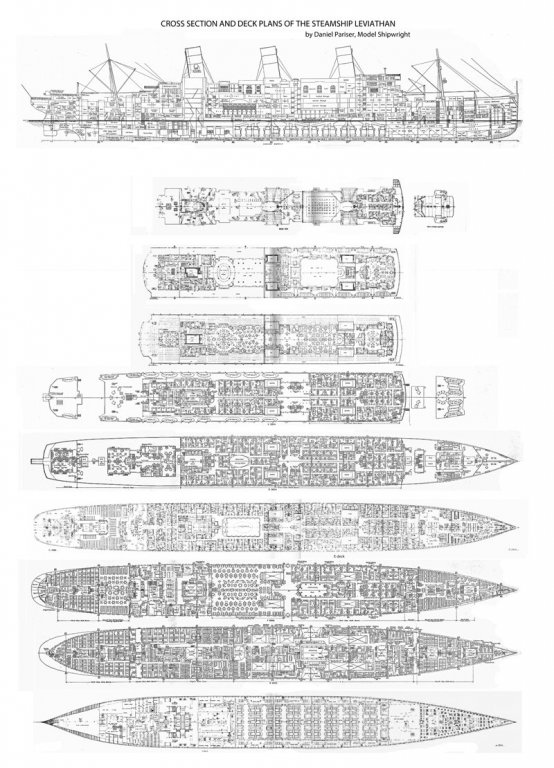
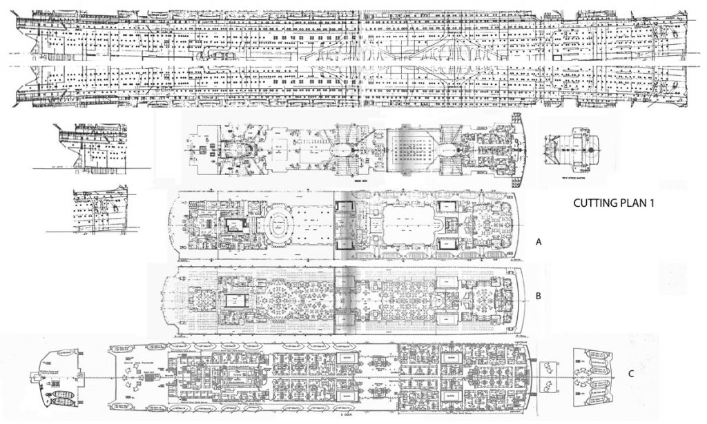
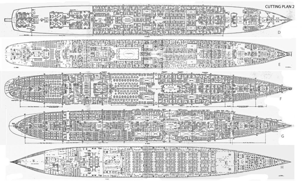
Hi to those of you who are following along, and those just looking in. I hope to make this journey informative and enjoyable for all, as it has been for me. Just hit the 'like' button if I am succeeding. The research for the project started, as with all my models of modern ships, by surfing what could be easily reached on the internet. Wikipedia gave me the basic history that I summarized in segment one, along with a few photographs. I always look at the research notes and sources at the bottom of a wiki article, which led me to the photo archives of the Naval History and Heritage Command (www.history.navy.mil), also known as the Naval Historical Center. This is a site maintained by the US Navy, and any of the photos that can be seen there are in the public domain. Fortunately, they had over 200 photos of her taken mostly while she was a troop ship during WW I, including this shot of one of the 6-inch guns that were installed so she could defend herself. Another excellent site is NavSource Naval History (www.navsource.org), an organization of volunteers who put together histories and photographs of US Navy vessels. Here there were many more photos, not just limited to those of her as a troop ship, but included those of her as the SS Vaterland before the war and as the SS Leviathan after the war. However, many of the images are copyright protected and so I used them only for research. A wider net was cast by searching Google images under all three names of the ship and a flood of photographs were found. Everything from high-resolution images of the liner’s deckhouse to low res blurry shots of the troop ship being filled with coal. Side branches led me to even more images. One of those was to an image of the cover of a huge six volume set of books by Frank O. Braynard, a noted maritime historian, prolific author, and one of the founders of South Street Seaport museum and historic area New York. The books were available on the net, but for a minimum of $200 for the set. Fortunately, the Merchant Marine Academy museum has a set, which I devoured. Here I found many more photos that I had not seen before. Unfortunately, the books had been produced in sepia-tone, and the images had lost some resolution in the process. I scanned those that gave me viewpoints that I did not already have, converted them to greyscale and played with contrast and lighting to get as much information out of them as I could. My final resource for images was a man I was introduced to by Professor Smith. Richard Rabbett of Boston is a liner enthusiast, especially Leviathan. He has studied her for years and has an impressive collection of artifacts, photos and knowledge. He even moderates a Facebook group about the ship at https://www.facebook.com/groups/ssleviathan/ He has generously given his time and advice to the project. Even now I rely on him when there is a particular perspective or camera angle that I do not have. From all of those I selected about 200 that cover just about every square inch of the exterior of the ship in as much detail as possible. Some, like this aerial view, from Richard, are unique and had to be included, despite the long range and some resolution problems. Getting a good set of plans was less easy. There are no complete ones that could be located either through a plans company or on the net, although some individual deck plans were found. They were incomplete and some were poorly rendered. I did find a good cross-section drawn by Gibbs & Cox during the conversion from troop ship to liner, but only a few deck plans. Nor was there a full set in the Braynard books. Some were printed on the inside covers, but they ran across the fold so some dimensions are questionable. Some others are labelled in German, so they must be plans of the SS Vaterland, before two conversions, and could only be relied on for the general outlines of the decks. Even the historian at Newport News Shipbuilding, where the last conversion took place, could not find a complete set, yet I know that it must exist, because Richard Rabbett has a set from the conversion. But his are both too large and too fragile to flatten for a scan. He took photos of them for me, but they would need a lot of work before they could be used to base a model on. Nonetheless, I managed to assemble digital images of almost all of the deck plans from the waterline up. They were dropped into Photoshop, cleaned up and cropped. Then each one needed to be straightened out, since most were scans of paper plans which had warped over time. A centerline was established and each warped segment of the plan was returned to center using the skew and distort functions of the program. They were resized to the 57” LOA of the model and assembled vertically in one image. I used the G&C cross section as my guide, and adjusted each deck plan to match it. Ultimately, this is what I came up with. It is highly reduced here, but it scans as 19,500 px by 27,000 px (119 megabytes) and would be 6’ x 9’ if printed full size. This plan got taken apart and assembled into two ‘cutting plans’ for convenience, then taken to the blueprint service company where three sets were printed out. At the top of cutting plan 1 is what I call the ‘porthole plan’. I took the plan for the exterior hull which I mirrored vertically so I would have the locations of every porthole, door and fitting on the hull, both port and starboard. Small sections of the bow and stern were also included from which I made templates to help shape the hull. Finally, I put together a triple image of the exterior plan, an exterior photo, and a plan view of the ship which I could easily consult during construction. This process took several weeks, during which I also ordered wood, surfed the net for fitting and fixtures, and got the shop in the upstate house cleared and cleaned. Next segment, we start cutting wood. Till then, be well Dan

.jpg.d2f08f5f27af5e0dd17de03572cb2941.jpg)
- 238 replies
-
- 21
-
-
- leviathan
- troop ship
- (and 2 more)
-
Hi Marc - Looking really good. I don't envy you painting the edges of the frieze pieces after priming. Dan
- 2,699 replies
-
- 2
-
-
- heller
- soleil royal
- (and 9 more)
-
Hi Charlie - Looking better and better. I like the new gratings and coamings. You might just round the corners a bit. Sharp corners and edges on a ship tossing in rough seas would be an invitation to serious injuries. Excellent progress overall. Dan
- 362 replies
-
- 2
-
-
- active
- revenue cutter
- (and 1 more)
-
Beautiful work, Michael. It has been quite an education to follow along with your restoration. I have bookmarked quite a number of places where you have furthered my education. Thanks, on many levels. Dan
- 749 replies
-
- 4
-
-
- albertic
- ocean liner
- (and 2 more)
-
Hi all, and welcome to this build log. I am honored by the many excellent modelers who are in my audience. Marc - yes, she will be a big one, but skinny. She will be exactly 57" long but only 6" max breadth. This is in 1/200 scale. In 1/192 (1/16"=1') she would be 59" long and 6 1/4" wide. I chose the smaller scale so I could source the wood much more easily, and the 4% difference is not noticeable. I did clear it with the powers that be. I did the heavy woodworking of making up the lifts and shaping the hull in the upstate house, but she is now in the Brooklyn drydock with decks and deckhouses going up. I will catch up the log with the construction at some point. Jan- yes, the starboard side dazzle was also quite bizarre and I am a bit glad that I don't have to do both sides. The civilian side will be the post-war colors of the United States Lines, since this is for the American Merchant Marine Academy museum. Nils - this museum has models in all sorts of scales. I never heard of a 1/96 requirement. If I had to build at that scale, the Leviathan model would be almost 10 feet long! Yeeesh ! Not only don't I have that kind of space in my city apartment, but I couldn't get it into the elevator after it was built. The smaller scale is better. Back soon Dan
- 238 replies
-
- 6
-
-
- leviathan
- troop ship
- (and 2 more)
-
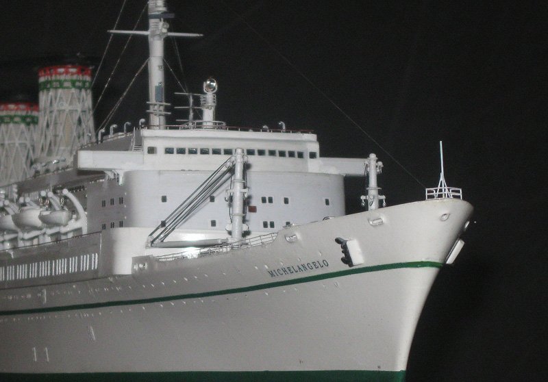
Thank you all. Your appreciation is highly appreciated and treasured. I am happy to have entertained you and perhaps added one or two tricks to your toolbox. I know that I learned a great deal during this project, both from the subject herself, the technical puzzles, and from the great friends that I have here. See you at the Leviathan drydock. Be well Dan
- 287 replies
-
- 4
-
-
- michelangelo
- ocean liner
- (and 1 more)
-
Beautiful work, as usual, Chuck. Excellent joinery, especially the tricky notches in the floor planks for the ribs. Dan
- 421 replies
-
- 5
-
-
- medway longboat
- Syren Ship Model Company
- (and 1 more)
-
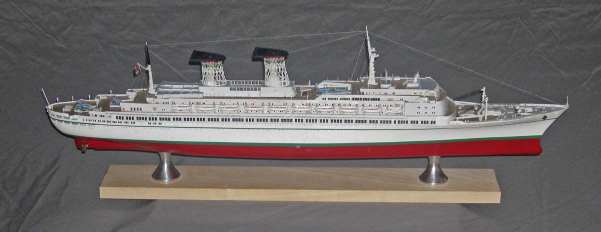
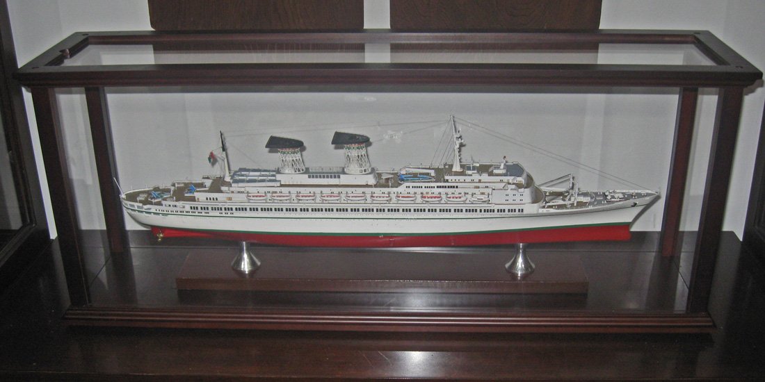
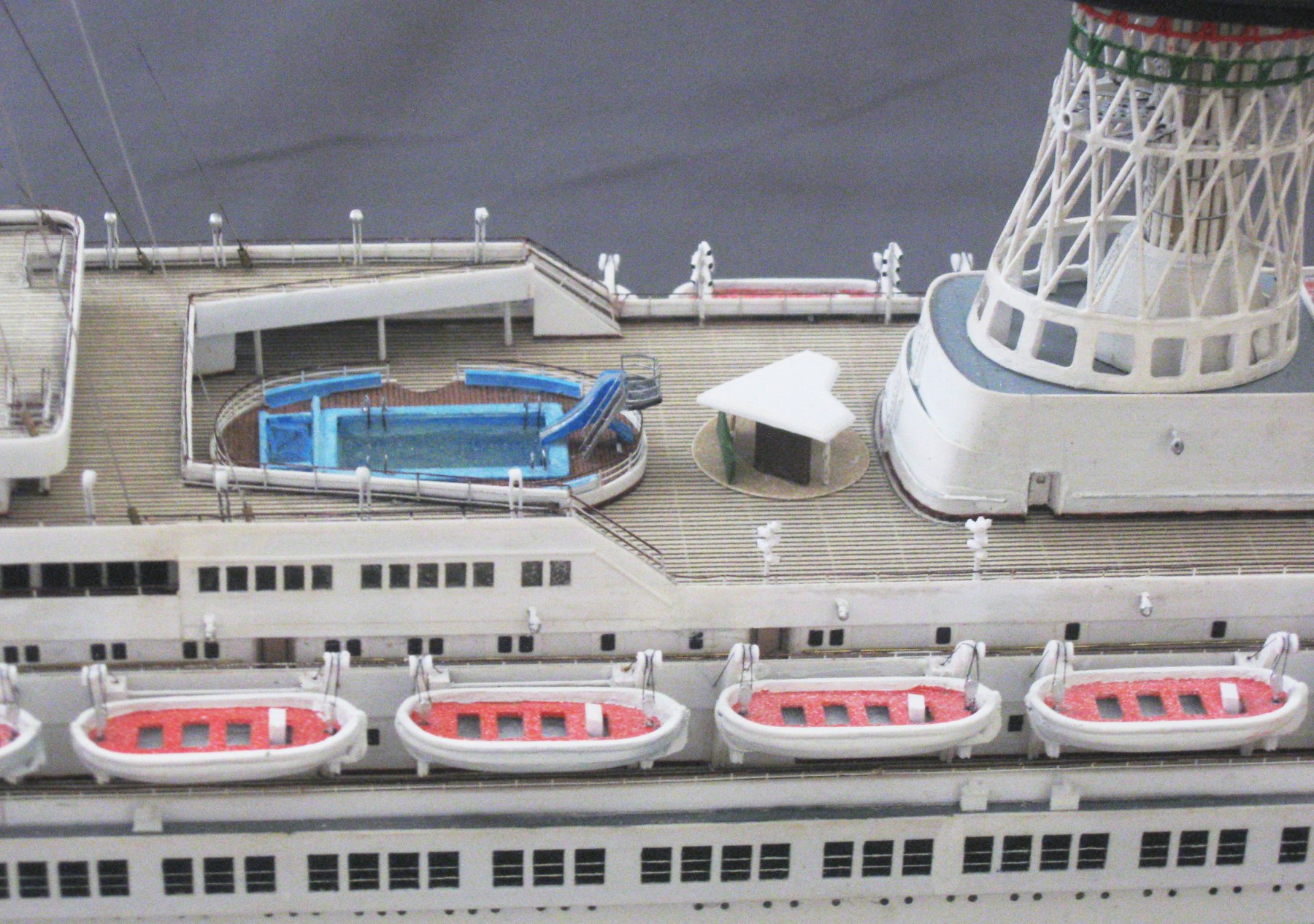
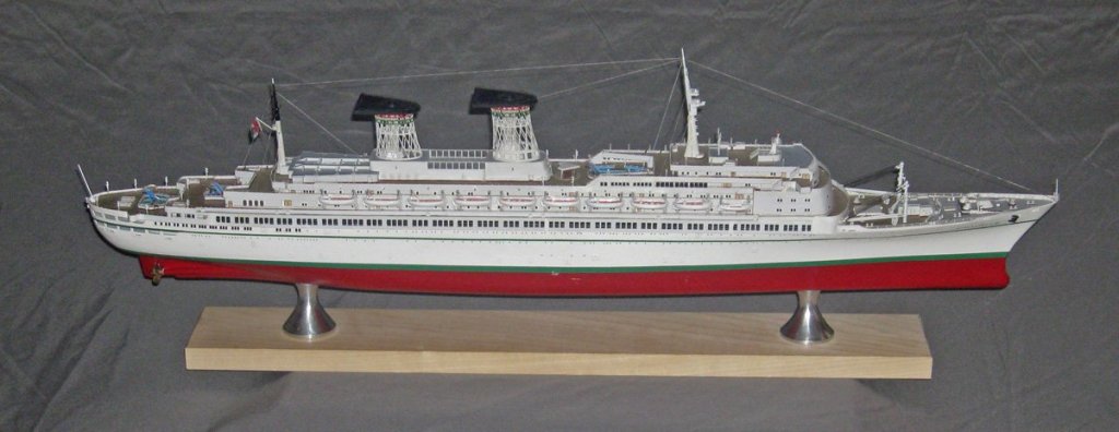
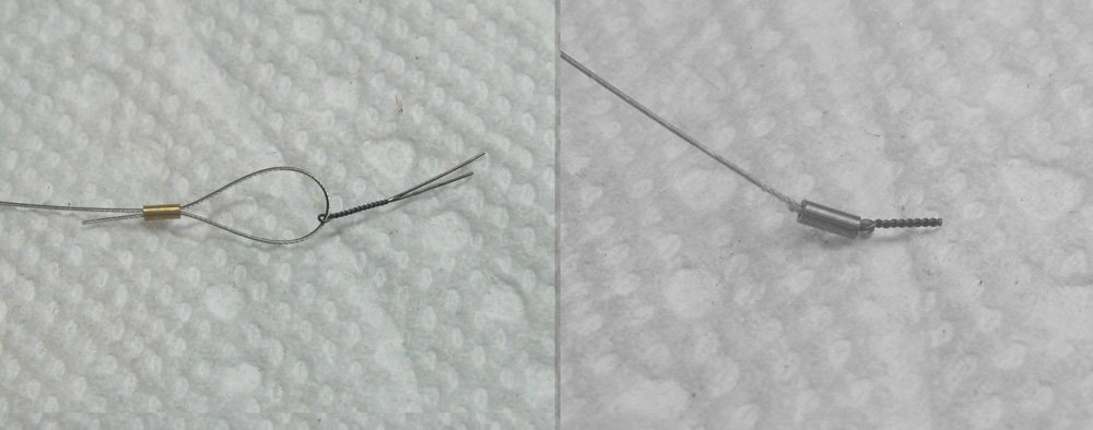
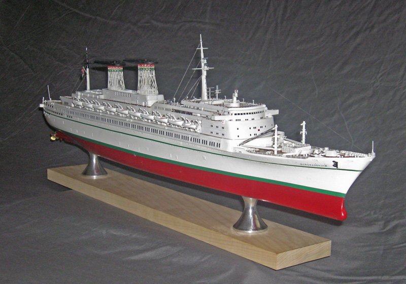
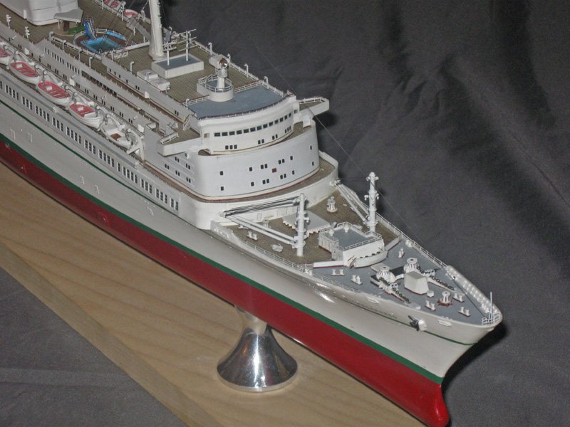
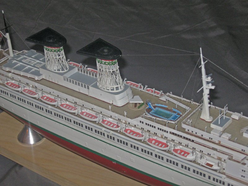
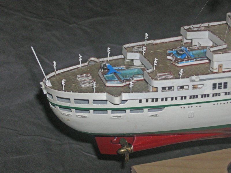
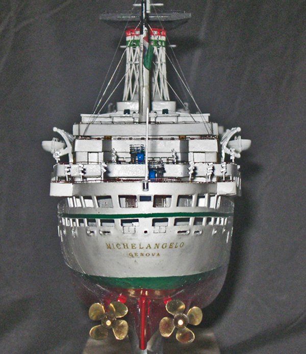
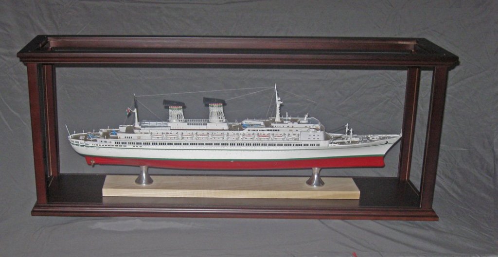
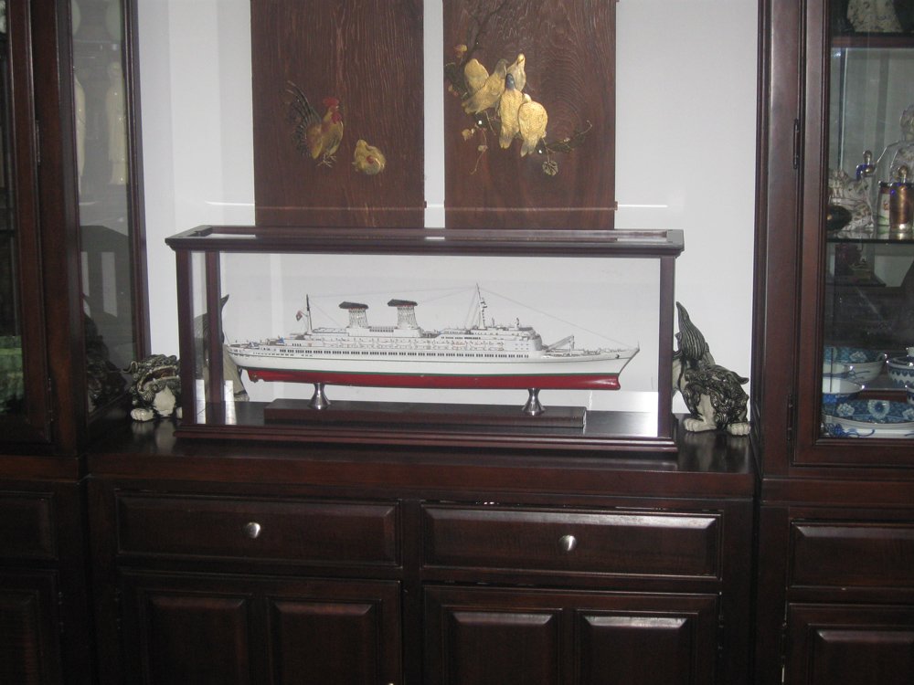
Hello again to all, and thank you all for staying with me on this journey of the SS Michelangelo project which ends with this final segment. My efforts are now focused on the next project, the USS/SS Leviathan, which you can follow by clicking on the new link in my signature, below. As the last segment ended I had made up and installed the three types of lights around the ship. The final detail was the rigging. This was fairly simple and consisted of only two types, the stays and the radio antenna. The stays were of three different weights, but all were made up in the same way. The lowest shrouds for the two masts and their forestays were done with Accu-Flex stainless steel beading wire in 0.0095” diameter, while the middle backstays were done in the slightly smaller 0.007” diameter. Despite these small sizes they are each laid up from 7 strands of stainless steel wire wrapped in a clear plastic coating. They look like metal because they are metal. The uppermost backstays and the lifts for the spars are made from silver fly tying line, about 0.005”. Each line was secured with a scale turnbuckle made from a small piece of brass tubing. The line was fed through the body of the turnbuckle, then through a small eyebolt twisted up from iron wire, then back through the turnbuckle tube. After the shaft of the eyebolt is glued in place the wire is pulled taut and the tube slid down to lock it in place. Then it is simply glued and the excess line clipped off and the turnbuckle painted silver. For size comparison, the background is a normal paper towel with its embossed pattern. Here is the finished model with the stays installed. The radio lines are black so they do not show up here. Taking a tour of the ship, here is the forward half with the winches, hatches, and cargo cranes of the bow working deck. The midships area has the main pool, the boats, and those 3-D printed cages for the funnels. And the stern, with the two smaller pools and the numerous complicated light poles. Viewed from dead astern I can see just a little wobble in the upper green stripe, but overall I am quite happy with her. And of course, the obligatory shot from low on the bow. The final decision was how to display and case her. I located a nice mahogany case on line and had it shipped from Vietnam. The shiny aluminum pedestals nicely set off the colors of the model, but the light maple wood base that I first selected just did not go. It did not match any of the colors, and made the model look too high in the case. Instead, I refinished the base to match the mahogany case and the results were, I think, a significant improvement. So now it is ready to motor off to someone else’s collection. I will be contacting brokers who deal in ship models to see if there is any interest. Frankly, my wife will not mind if it does not sell. She thinks it looks perfect on our sideboard. I have to agree, though I say it who shouldn’t. Meanwhile, I will be posting my progress on the Leviathan project. If you enjoyed this journey with me, I invite your participation, comments and suggestions on that one, as always. And as always, be well. Dan

- 287 replies
-
- 22
-
-
- michelangelo
- ocean liner
- (and 1 more)
-
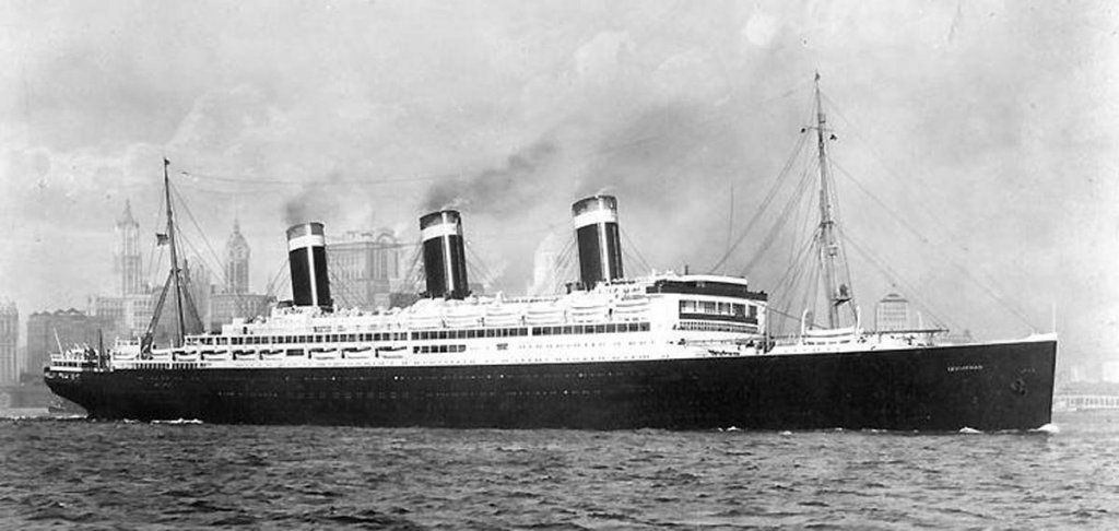
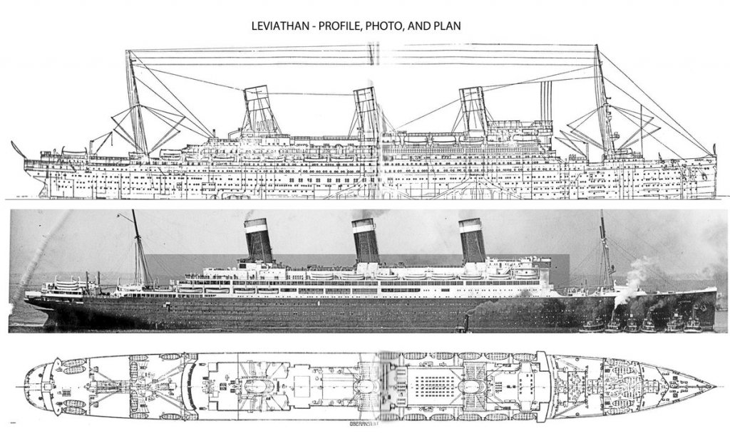
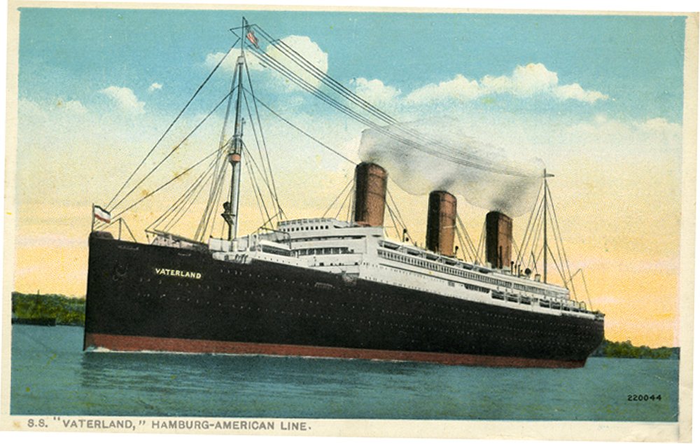
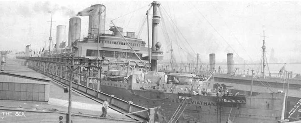
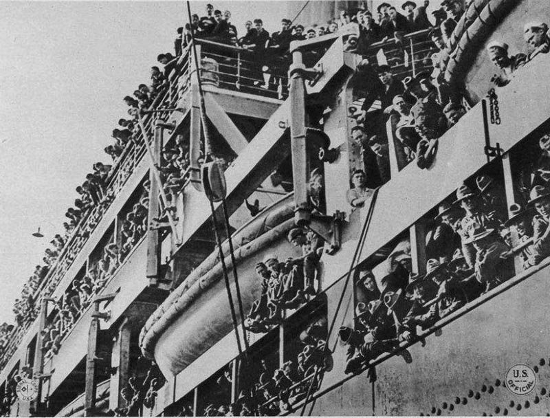
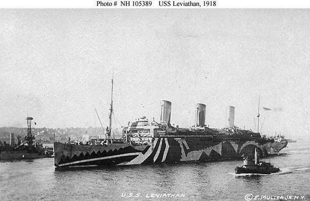
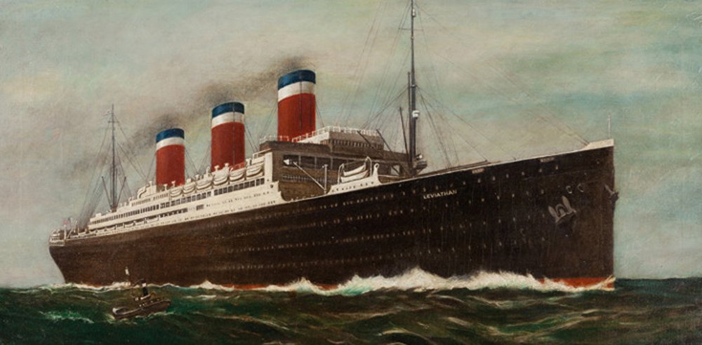
Hello to everyone who followed me from the SS Michelangelo build log. I hope that you will enjoy this one as well. This is the first of what will be 7 models built over the next 4 years for the museum at the US Merchant Marine Academy at Kings’ Point, NY. It is a gem of a small museum, open to the public, well worth visiting for the history of the US merchant marine during war and peace, as well as dozens of beautiful and informative ship models. This first model is of the most famous ship that I knew nothing about until I started this commission. The USS/SS Leviathan was, in her day, the largest ship in the world and a major contributor to the allied victory in World War I. Built in 1913 by Blohm & Voss Shipyards in Germany, she began service in 1914 as the SS Vaterland for the Hamburg-American Line. Displacing 54, 282 tons she was 100 feet in breadth and 950 feet long, some 67 feet longer than RMS Titanic, yet her engines could push her along at a very respectable 26 knots. After only one and a half trips from Hamburg to New York she found herself here in August when the war broke out. She was interned by the USA, a neutral country at the time, and spent the next three years in Hoboken, NJ. When America joined the war she was seized (stolen, the Germans say) and taken into the US Navy as a troop ship, renamed the USS Leviathan. As a troop ship she made a major contribution to the allied victory. In her 14 round trips she carried over 100,000 soldiers to the front, and the same number back, some wounded, some with the Spanish flu, but most just glad to be going home. On one return trip she carried over 12,000 troops plus another 2,500 officers, sailors and nurses, a total of over 14,500 souls aboard. During her first transit she stopped off in Liverpool where she took on a coat of ‘dazzle’ camouflage paint. Dazzle was developed by British marine artist Norman Wilkinson and used complex geometric patterns and contrasting colors to disguise the outline of the ship from German submarines and torpedo boats. The scheme for the Leviathan was particularly bizarre, but seems to have worked, since she was never attacked. After the war she was taken into the United States Lines as their flagship. She was completely renovated by Gibbs & Cox, with little help from Blohm & Voss, who were still smarting at the seizure of their masterpiece. Restored to her former splendor by 1923 she cruised from New York for the next decade before the newer, sleeker ships, the SS America and the SS United States, took her place. As I mentioned in the Michelangelo log, my contract is to provide a model that reflects, on the port side, her dazzling appearance during the war, while the starboard side will show her civilian colors. Down the centerline things will get dicey, and there will be many puzzles and challenges along the way. It should be an interesting trip. Next, research and plans. Be well Dan
- 238 replies
-
- 17
-
-
- leviathan
- troop ship
- (and 2 more)
-
Coming along beautifully, Marc. Really looking forward to seeing her in person. Well done. Dan
- 2,699 replies
-
- 3
-
-
- heller
- soleil royal
- (and 9 more)
-
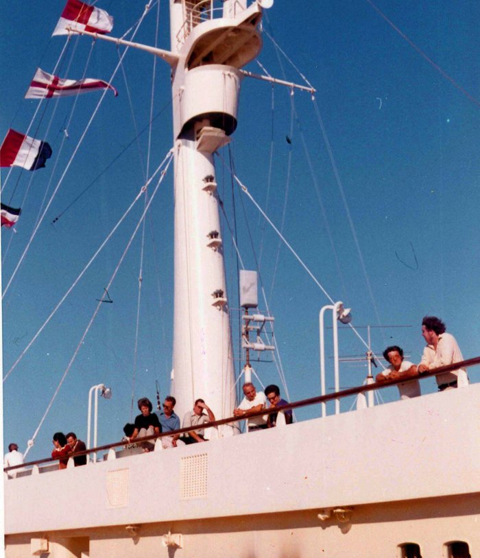
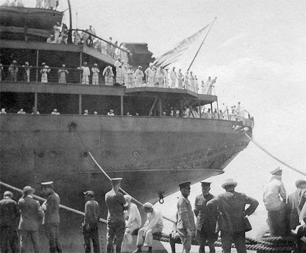
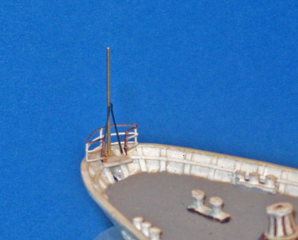
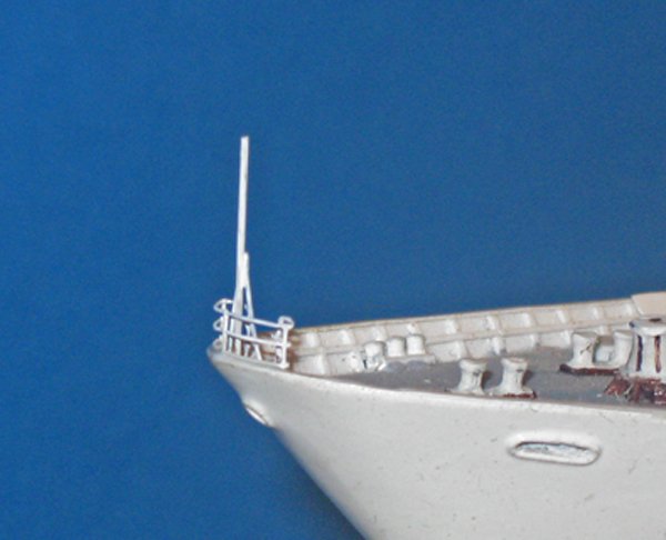
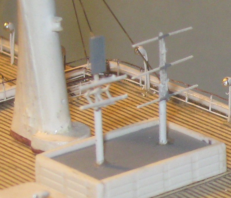
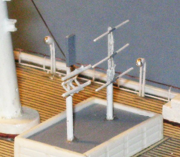
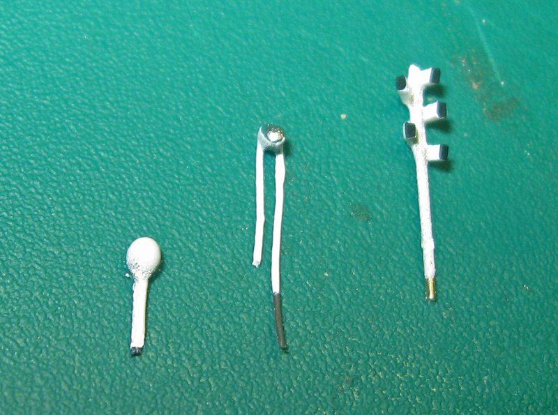
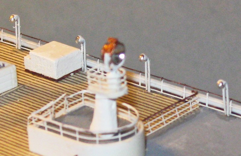
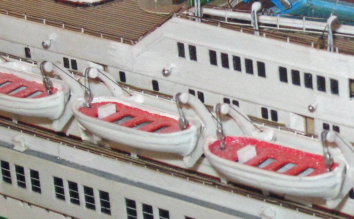
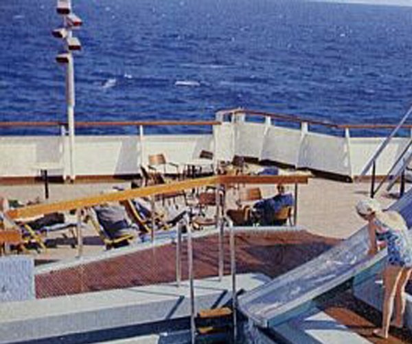
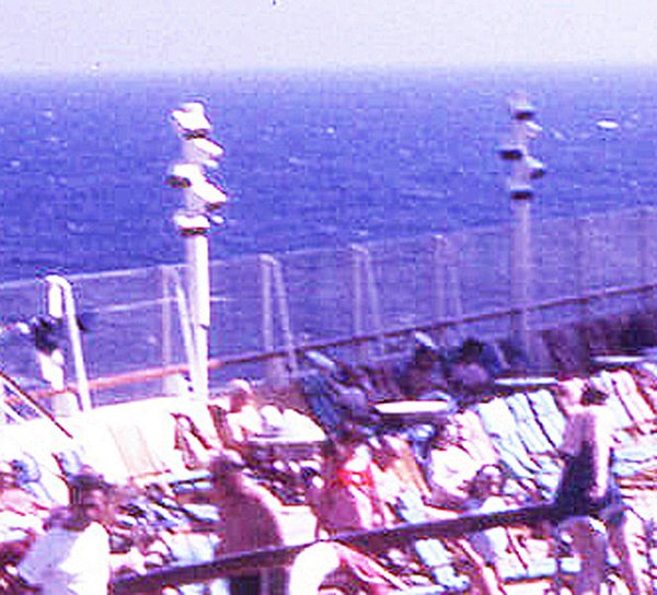
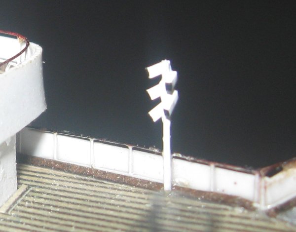
Hello all – Thanks to all, as always, for the many likes and compliments. I trust every one of my American friends has had a great Labor Day holiday with friends and family, and equally great wishes for everyone across the globe who graces my work with your interest. We are reaching the end of this project so this will be the penultimate report – a short one on the final fiddly details. The first detail was the bow ensign that was left to the end rather than endanger it during construction. It is built up with a small platform above the bow hawse hole. This is then topped by a vertical ensign post of 0.02” brass rod supported by a ‘vee’ brace of 0.011 wire. Two-bar PE railings surround all. And here it is after painting off the model and installation. The next detailed fittings are the two radio masts rising from the radio shack on the Belvidere deck. They are not detailed on the plans, but in this photo you can see them behind the people at the rail. They were built up from brass rod, tiny plastic pieces, and PE railings that were cut, shaped, and adapted to new uses. In the photograph above you can see one type of light on the ship, the ones that rise on two bars, then bend at the top to illuminate the deck. In fact, there are three types of lights in various locations around the ship. The first type was made by bending iron wire back on itself very tightly. The doubled end was then bent down toward the deck. One leg of the stand was cut to 10mm while the second was left long to fit a hole in the deck. The light body was formed from a drop of epoxy whose surface tension is used to pull it into a ball as it hardens. The light itself is represented by a drop of gloss silver enamel. Here too the properties of surface tension were my friend. A small drop of paint was picked up in the end of a toothpick. When applied to the fitting it drew itself up and dried as a perfect circle. The second type are simple floodlights on the end of single posts. They are mostly located above the lifeboats to illuminate them if there were a nighttime evacuation. These were also formed with epoxy and silver paint using surface tension. The final type of light is the most complex. Five rectangular light bodies are mounted on a pillar with the lights angled to either side. They do not show up well on the plans and the photographs are not the clearest, but were enough to give me a good idea of what was needed. A post of 0.032” brass rod was painted with white glue and five tiny lengths of plastic rod 0.015” x 0.020” were delicately adhered to the brass. As the glue set up I teased the lights into position. When dry the joints were reinforced with a drop of thin cyano. I use this double gluing technique a lot on small parts. It takes advantage of the sticky nature of PVA glue to get things into position, and the CA then can strengthen the joints without disturbing the positions of the parts. When all was dry they were spray painted with gloss white and the faces of the lights were picked out in black with the paint on a toothpick. So here is a shot of the midships area with all three types of lights. I am pleased with how they came out, and happier still with how much ‘texture’ they add to the look of the model. That’s it for now. The final segment will be posted soon with the model mounted, cased, and ready to travel. Until then, be well. Dan


- 287 replies
-
- 15
-
-
- michelangelo
- ocean liner
- (and 1 more)
-
Yves - Thanks for the translation. There is a similar fixture on English ships of the period called a 'pissdale'. I think I have seen drawings of one on HMS Victory in the book by Longridge. I had never seen one directly below a gun barrel, but I suppose it makes sense since that space would not be used for anything else, and you wouldn't want the gunners leaving their post or wetting themselves. Be well Dan
- 128 replies
-
- 4
-
-
- mordaunt
- battle station
- (and 1 more)
-
Hi Dave - Very nice work on the wreath. I like the added shadow lines. They should make it 'pop' when viewed with anything less than a macro lens. Yes, removing the ring would be better with this style of carriage. The train tackle hooks directly into the eyebolt. Aviaamator - do you know the English translation of the underlined text for the spout detail in the drawing you posted? I have never seen that particular detail. My French is not up to the task. Thanks. Dan
- 128 replies
-
- 3
-
-
- mordaunt
- battle station
- (and 1 more)
-
Hi Marc - No, laser cutting works for plastic too. My davits for Michelangelo are plastic. You can specify thickness and 0.020" will not be a problem. I know that Syren does both wood and a resin/paper material. If they are not satisfactory, then club member Charlie Zardoz works in plastic. You clearly need many, many of these small items, and trying to cast them seems to be a great deal of work. Best of success, whatever you decide. Dan
- 2,699 replies
-
- 3
-
-
- heller
- soleil royal
- (and 9 more)
-
Hi Marc - All those FdL pieces came out almost identically. Quite an achievement. Your perseverance is inspiring. For the scrolls, have you considered laser cutting like I used for the Michelangelo boat davits? I know Syren Models does it. You can specify the thickness you want and the material to be used. The scrollwork could be laser etched. Since you will be painting them the char from the process shouldn't be a problem. I understand that 3-D services can also do it, but I don't know the process. Always good to watch your progress. Dan
- 2,699 replies
-
- 3
-
-
- heller
- soleil royal
- (and 9 more)
-
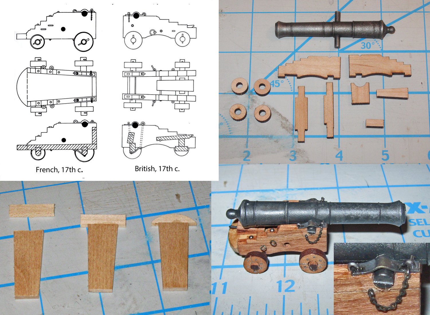
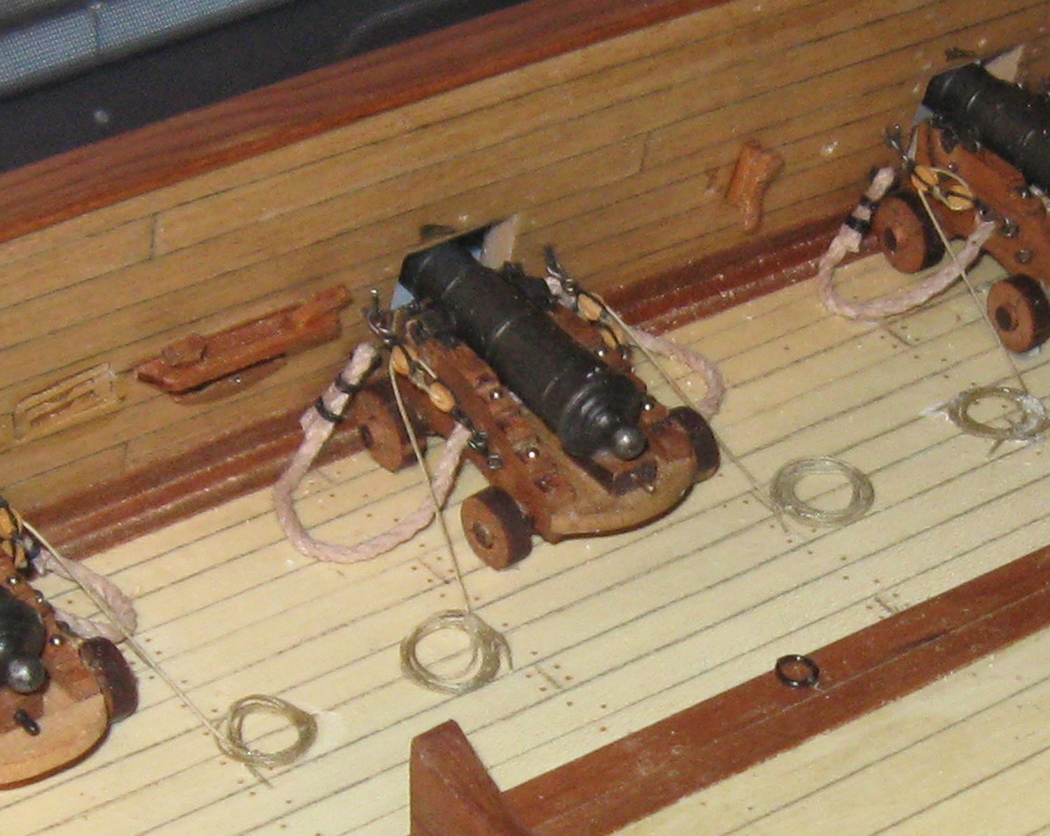
Hi Don - This looks like it will be a fascinating project, and I will be following along with interest. The barrels in particular are quite nice. However, before you go much further, I wonder where your carriage design comes from. It has always been my understanding that there were significant differences between British 17th C. carriages and those of the French/Dutch/Continental practice. The most significant ones are that the Continental ones have solid base plates, while the British ones have open bottoms, and because of that the breaching ropes for the Continental cannon went through holes in the carriage itself, while the British ones are secured to the gun's cascabel. Here is a combination illustration of the two designs and how I converted a commercially available cannon kit from British style to French style. I made up a base plate and a bumper at the rear of the carriage, then drilled a hole through the carriage for the breaching rope. And here is how it looks fully rigged and at its battle station. On the other hand, you seem to have a solid base plate in the Continental style, yet your breaching rope goes to the cascabel in the British style. It leaves me unsure of which one you intended. I do not mean to make you go back to the beginning, and there is certainly no need to be hyper-concerned with historic accuracy, but such a discrepancy may impact the popularity of your project. Whatever you decide, you have my best wishes for success. Dan