HOLIDAY DONATION DRIVE - SUPPORT MSW - DO YOUR PART TO KEEP THIS GREAT FORUM GOING! (83 donations so far out of 49,000 members - C'mon guys!)
×


Dr PR
-
Posts
2,438 -
Joined
-
Last visited
Content Type
Profiles
Forums
Gallery
Events
Everything posted by Dr PR
-
 Mark, I agree with Keith, the mast angles don't look right. First of all, I studied plans and drawings for 17 Baltimore clippers, and on every ship the main mast had greater rake than the fore mast - no exceptions. Here are the angles I found: Fore mast - 11.5 degrees average, with a range of 7-16 degrees Main mast - 13.75 degree average, with a range of 8-22 degrees I have never seen a plan, drawing, model or painting of a topsail schooner with greater rake on the fore mast than the main mast. Second, be careful about the reference for establishing the rake angles. The angles I listed above are relative to the water line. But the angles measured by sardonic meow are relative to the bottom of the keel! All of these ships had a deeper keel at the stern than the bow, so the keel was at an angle to the normal water line. You can see the difference in the drawing of the Musquidobit in post #114. The solid line just below the chains is the waterline. I would use angles similar to the model of the Lynx in post #113. The main mast has a greater rake than the fore mast. While it was possible to change the mast rake a bit by adjusting the wedges at the partners, it wasn't much of a change. The British could have reconstructed the mast steps to change the rake - they did shorten the masts on some captured American vessels - but unless you have documentation for this I would stick with the Lynx rake angles. **** I worked out a fairly simple way to set the mast angles on my Albatross build: https://modelshipworld.com/topic/19611-albatros-by-dr-pr-mantua-scale-148-revenue-cutter-kitbash-about-1815/?do=findComment&comment=599087 This let me set the rake angle and still allowed me to adjust the port-starboard angle to perpendicular with the horizontal.
 -
More good advice! Thanks! I like the suggestion of rigging the boat as if it were ready for sea and anchor detail. On the schooner model I have rigged one anchor as if it has just been fished, so the ship would be at sea and anchor detail (if that's what they called it in the early 1800s in the Revenue Service). The boat would be hanging from the davits ready to launch - or just recovered. The ship has most of the sails rigged so I think of it as having just weighed anchor and getting underway. The schooner has no space on deck for boats, not even a small one like this. But I suspect the real vessels had more than one boat. It was common to tow some or all of the boats rather than carry them on board. Some ships had davits rigged on the sides at the channels and I thought of doing that but I have seen no drawings or paintings showing this for a "Baltimore clipper" topsail schooner. But I have seen several plans and paintings showing a small boat hanging from davits at the stern like I am doing on the model. Note: The "booms" Trevor's quote refers to were spare masts that were carried on deck. The boats were stowed on these booms.
- 54 replies
-
- 1
-

-
- 18 ft cutter
- ships boat
- (and 1 more)
-
Your advice is worth a lot more than $0.02!
-
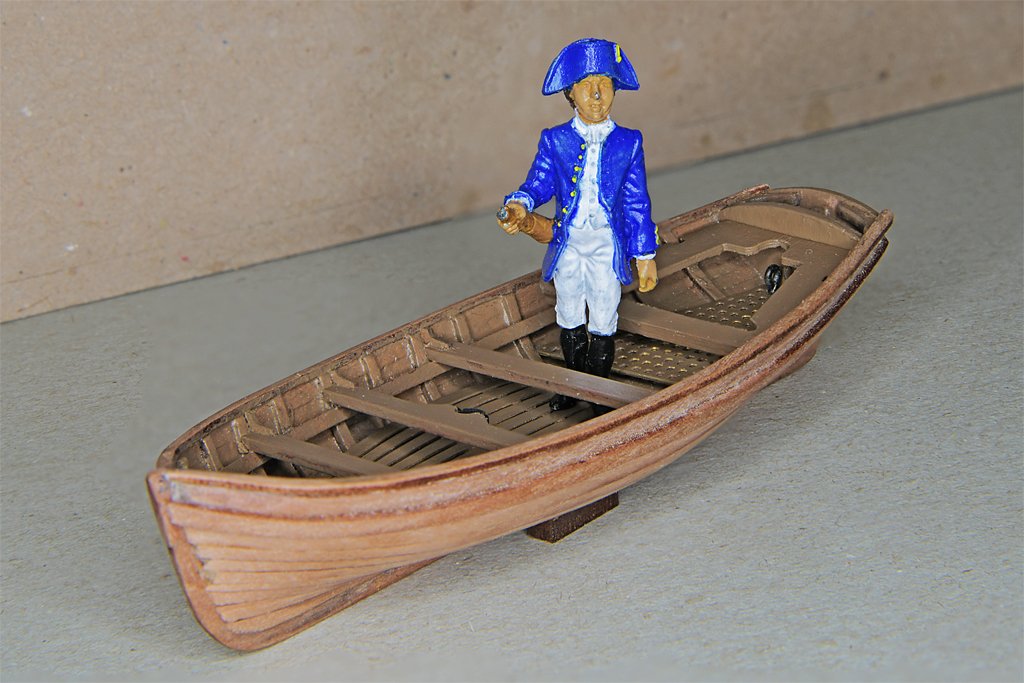
Steve's last post on his Prince build reminded me of the midshipman figure for my topsail schooner. This is an Amati 35mm figure - about 5 1/2 feet (1.7 meters) with hat at 1:48 scale . A 14 foot boat is pretty small!
- 54 replies
-
- 4
-
-
- 18 ft cutter
- ships boat
- (and 1 more)
-
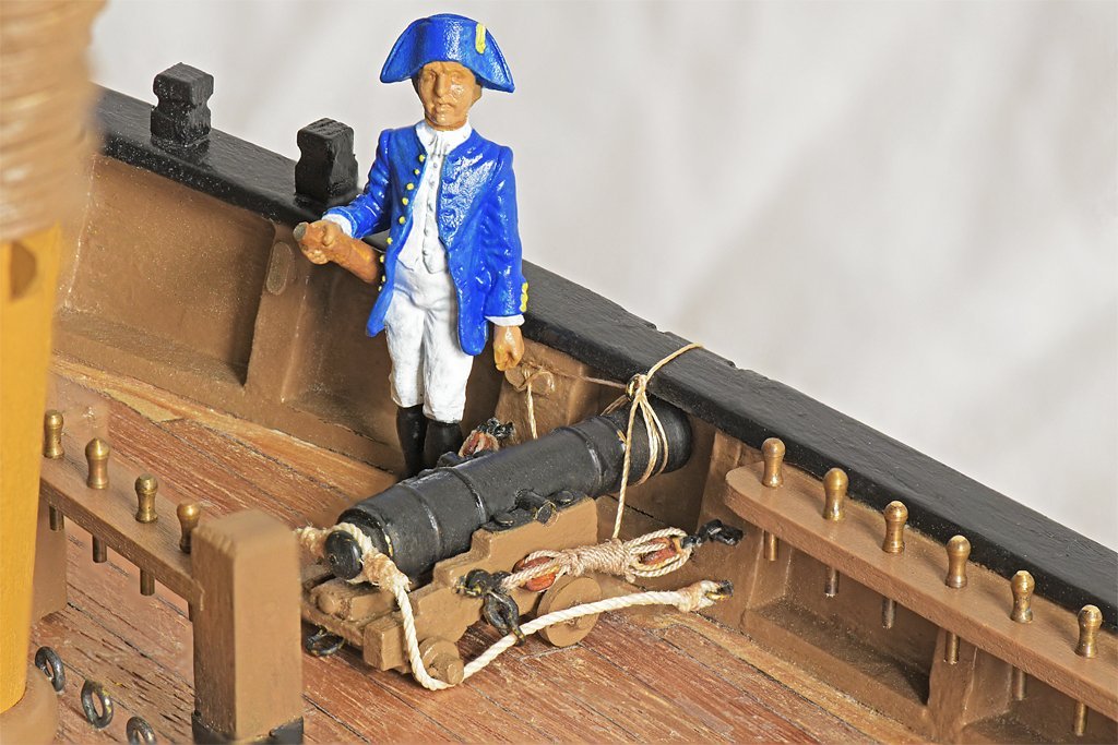
I used your Amati "captain" figure on my schooner build. It makes a good size reference for details. The six pounder cannons aren't very large and the figure shows this off nicely. However, my build is 1:48, so this fellow is pretty short. The 35 mm part (with hat) is about 5 1/2 feet (1.7 meters) at this scale, or closer to 5 feet without the hat. So I think he is a midshipman and not the Captain. But the telescope indicates he is the Officer of the Deck (OOD). I chose the colors of the US Navy uniform of about 1815. Thanks for posting pictures of the other figures. I would like to add a few more crew to enhance the anchor fishing "diorama" that I put on the model.
-
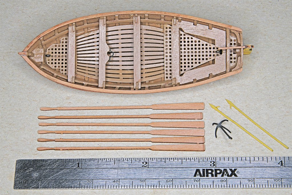
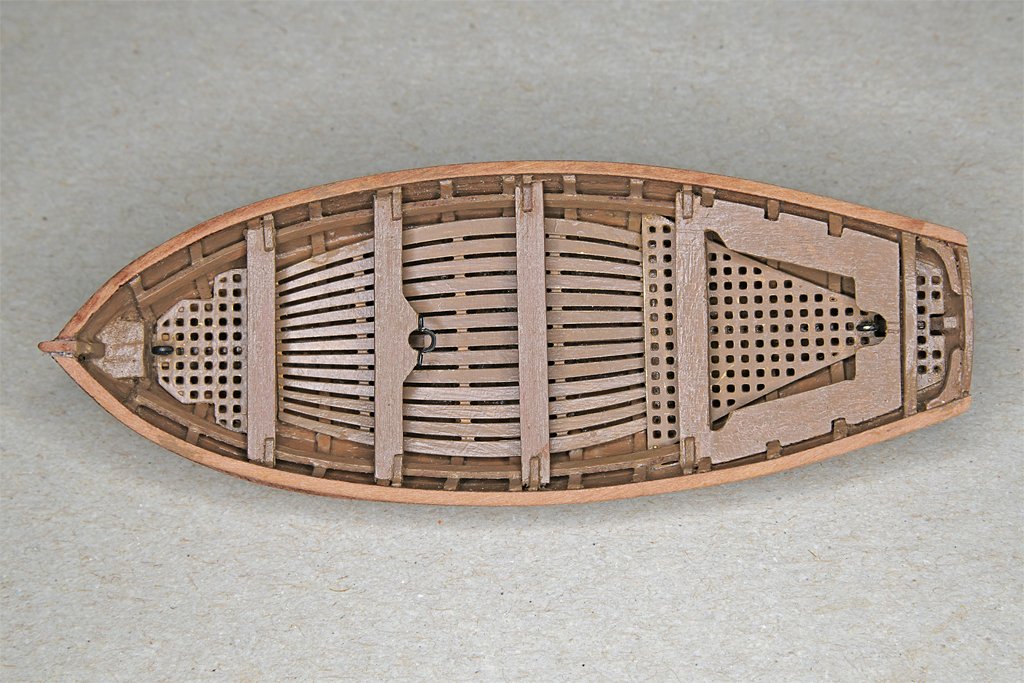
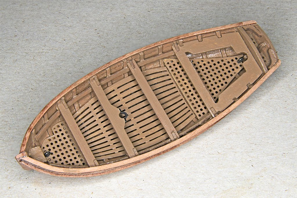
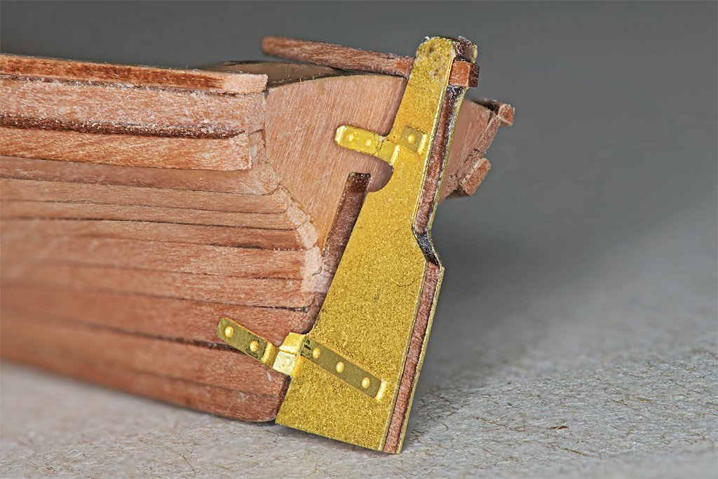
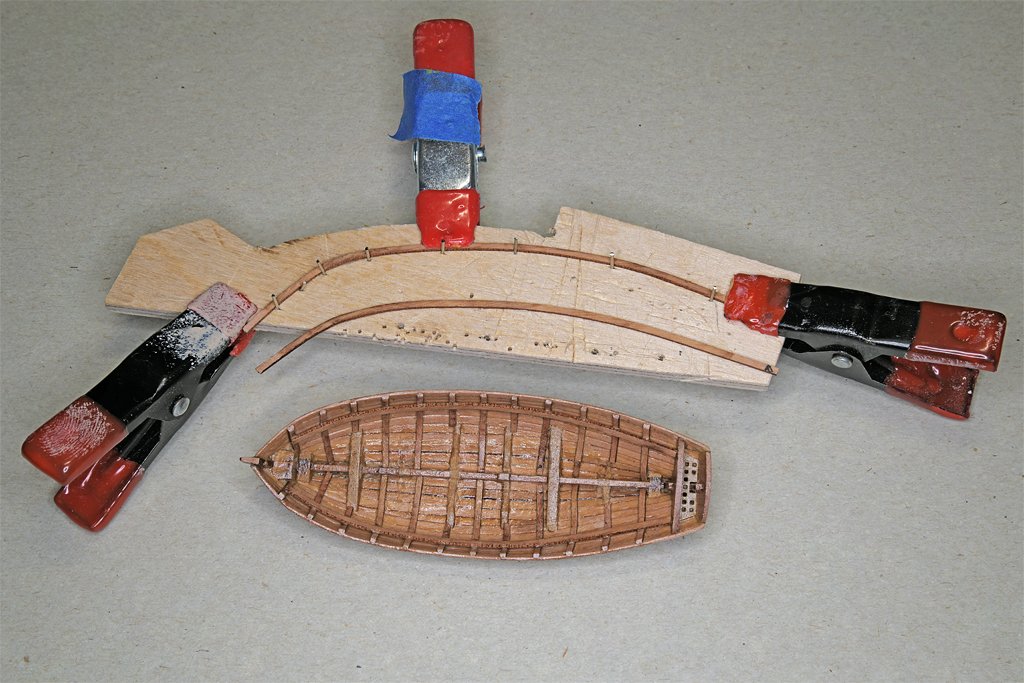
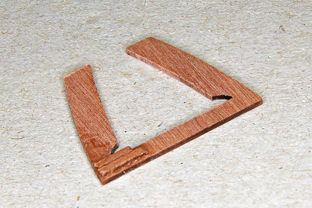
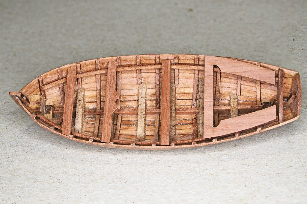
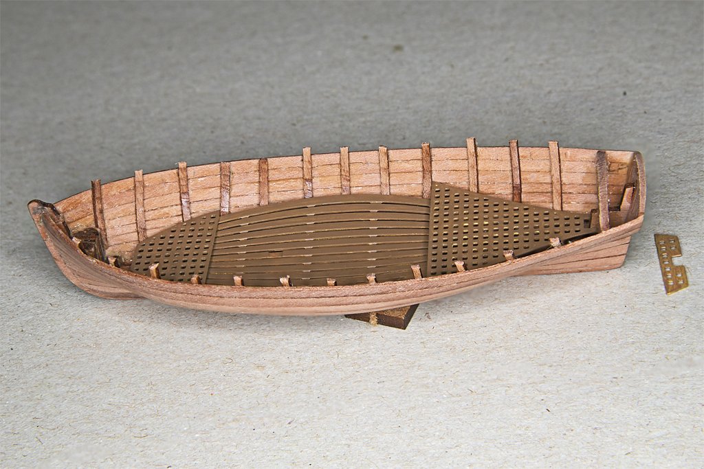
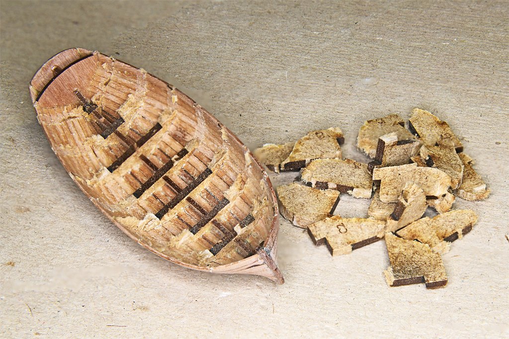
The boat is almost completed except for cutting the rowlocks and painting. I finished the aft seat and then installed all of the seats. Knees were glued at the stern inside the hull planking and transom. Eight small knees were placed at the ends of the seats. These are nice details, but very small. The kit includes sixteen pieces and that should tell you something! I lost two while sanding off the char and bit of the tab from the laser cut - tweezers twisted and launched them into the matrix somewhere. Because I added the cap rail I had to trim the tops of the knees a bit to fit under the rail. The details in this kit are very nice. The boat will really enhance the topsail schooner model. Now I need to do some more research. I still have the rudder to deal with. Note: in these photos the rudder is not glued in place, but is just held in position for the photos by the friction of the single tab near the bottom. So it is not aligned perfectly. The detailed straps are nice, but the design assumes the rudder will be attached to the boat. But would it be if it was hanging over the side/stern from davits? Or would the rudder be removed and stowed in the boat? If I don't attach the rudder I will need to make the straps and gudgeons on the transom and hull. And I will need to make the pintles on the rudder. The tiller on the rudder also poses a challenge. If the rudder is attached according to the instructions the tiller extends over the eyebolt for the boat falls and will interfere with the boat tackle. I can shorten the tiller a bit, but it already looks too short to my eye. The kit provides six wooden oars, two photo etch boat hooks, and the neatest tiny boat anchor I have seen. Would these items have been stowed in a boat hanging over the stern on davits? Following seas likely would pound the boat occasionally, and sometimes flood it. This could wash things out of the boat. What to do, what to do ... ? The ruler shows the size of the boat (3 7/16 inch or 87 mm) without the rudder.
- 54 replies
-
- 8
-
-
- 18 ft cutter
- ships boat
- (and 1 more)
-
May's Boats of Men-of-War (page 33) does say the rectangular "oar locks" cut into the top plank on the boat hull were introduced with the cutter type boat. He says an extra plank was added above that other boats had to increase the freeboard. But thole pins on this plank (or cap rail) would have placed the oars too high. Therefore the rectangular notches were cut into the top plank to serve as rowlocks, with the oars at a convenient height above the thwarts. Mays says the cutter was introduced in the first quarter of the 18th century, and the rowlocks cut into the top strake were different from every other boat type at that time. The other boats had thole pins. So it seems that in the Royal Navy these rowlocks cut into the top strake were not used before 1700. I don't know about other navies or commercial vessels.
-
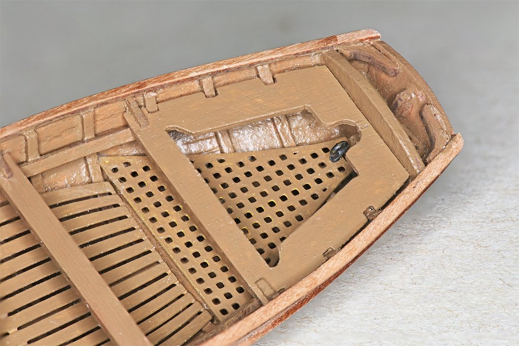
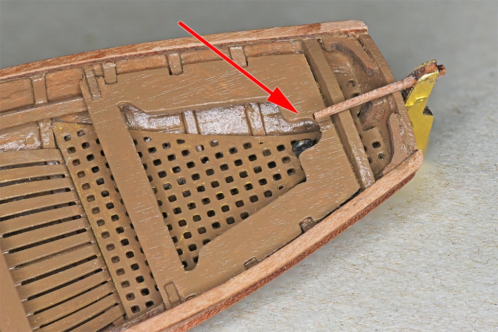
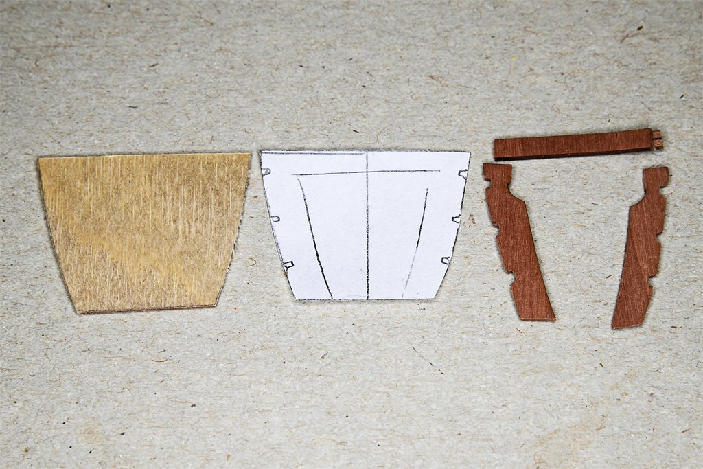
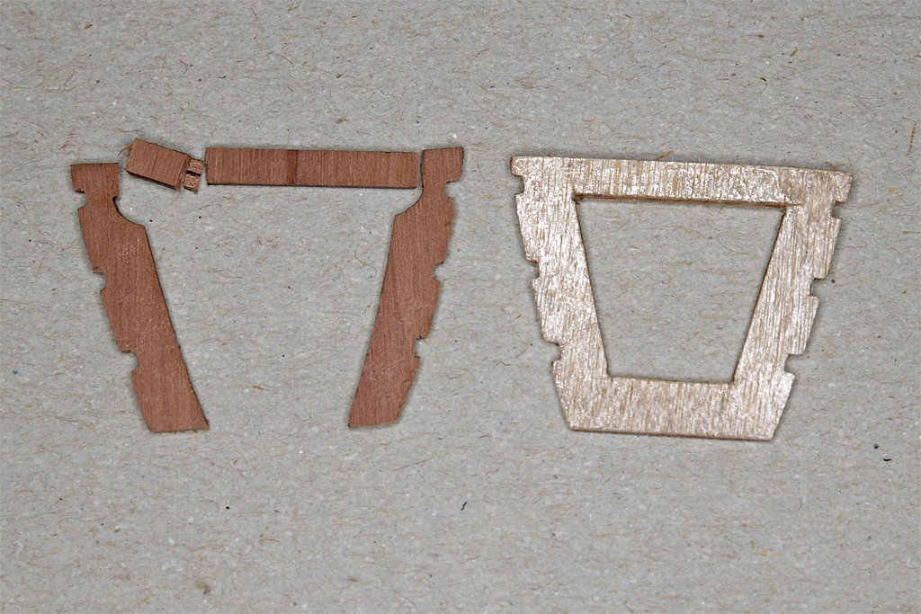
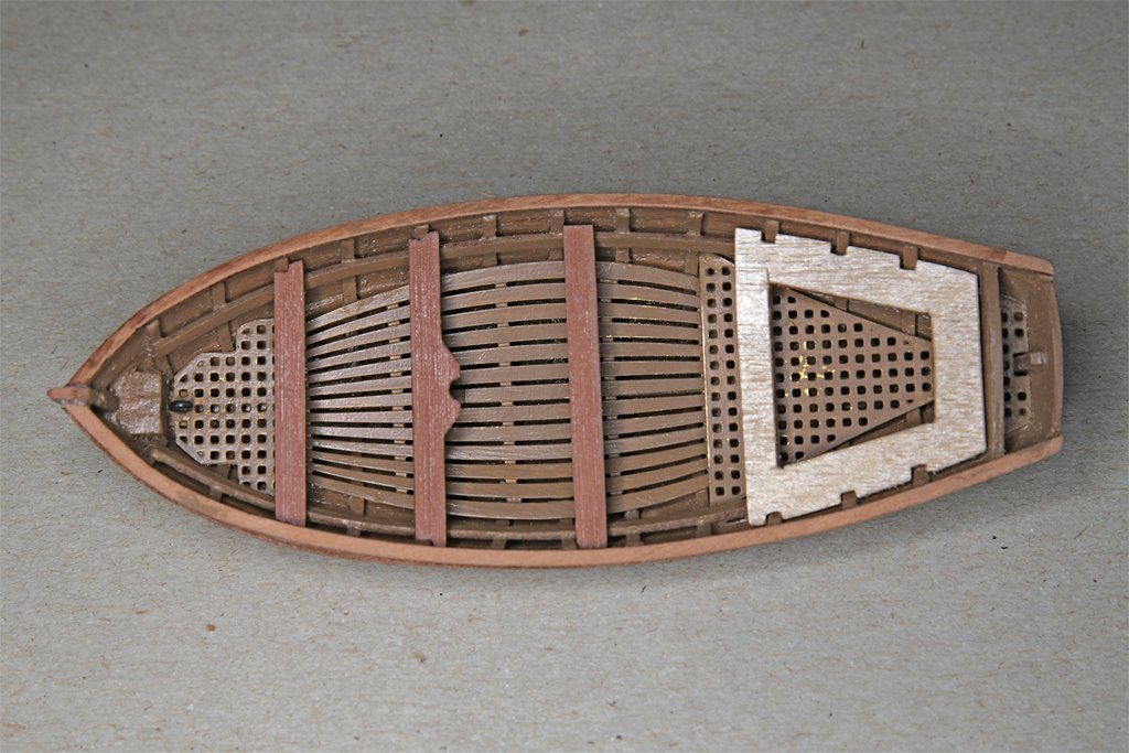
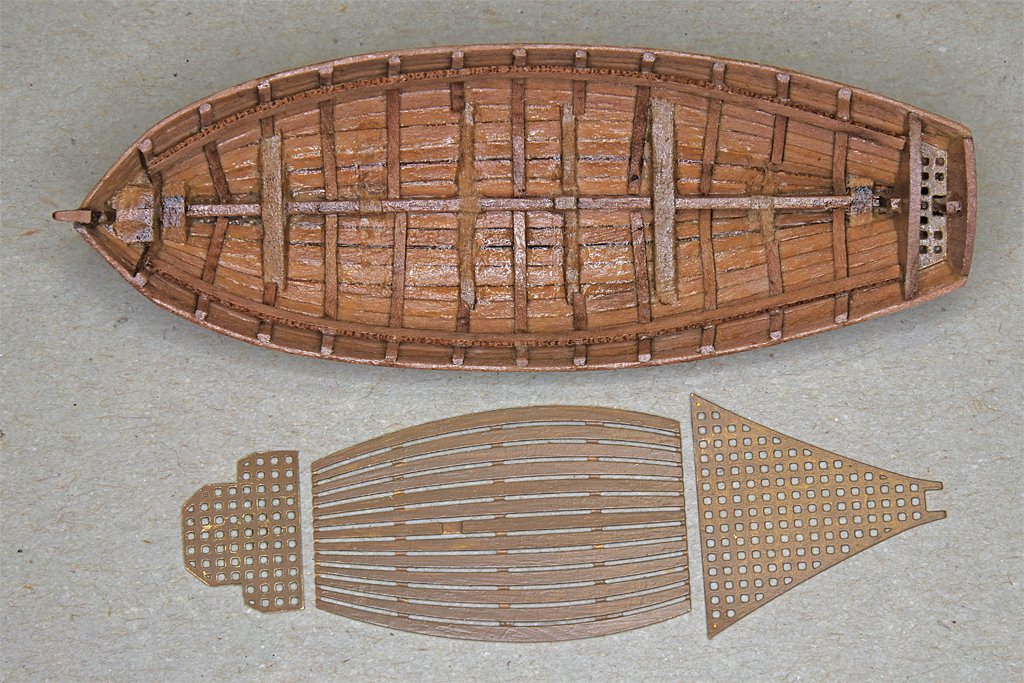
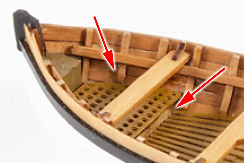
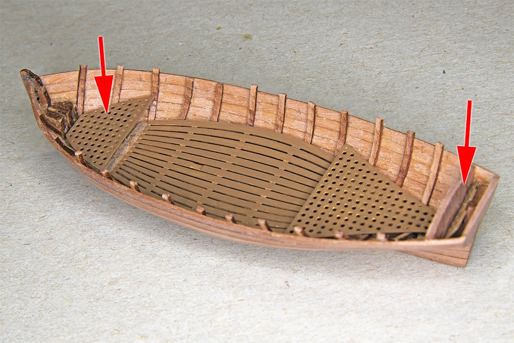
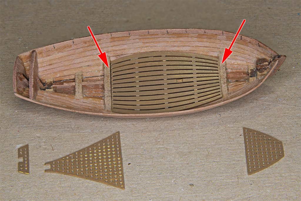
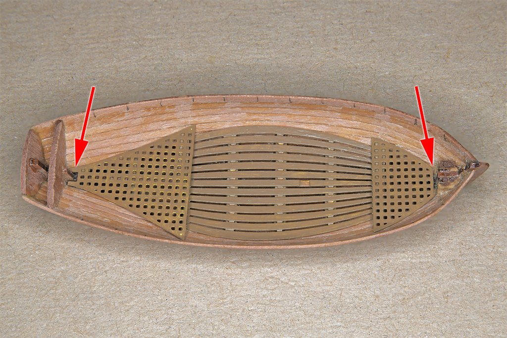
Installation of the deck panels was next. Neither the front or rear grating pieces fit down to the MDF bulkhead parts, but were "floating" in the air, suspended by points that touched the hull planking. I added three thin support blocks for the front grating and one for the rear piece. The gratings will rest on these supports. The foremost of the front blocks and the block at the rear serve dual purposes. In addition to supporting the gratings they also provide wood for eyebolts to "screw" into. The boat will hang from the boat tackle on the stern davits, and hooks on the lower blocks will engage these eye bolts. Here are photos of the deck plates in place. Arrows in the right hand photo mark the fore and aft eyebolts for the boat tackle. The seats were next. The front three presented no problems. In order for the middle seat's mast support to be positioned over the mast foot in the photo etch deck planks I had to notch the ends a bit on both sides to fit around ribs. Then I spaced the fore and aft thwarts about the same distance from the center piece. The forward seat also had to be notched to fit around ribs. The large aft seat was a pain in the posterior! I mentioned earlier that the thin seat at the front broke along the grain while I was removing laser char. It broke twice more while I was trying to notch the piece to fit over the ribs. This piece was also too narrow at the aft end to fit properly into the hull when resting on the seat support strips. I decided to make a new part from 0.03125 inch (1/32 inch, 0.8 mm) thick plywood. I made a paper template to fit the shape of the hull interior and used this to cut the shape from the plywood. Then it was just a matter of repeated shaping and test fitting until I got a part that fit correctly into the hull, resting on the seat support strips. Then the center part was cut out. This 0.8 mm plywood piece is thinner than the 1 mm kit part, but is MUCH stronger. It flexes without breaking. Maybe it is too flexible, so I glued a cross piece under the front seat to stiffen it a bit. This support fits between the seat support strips that run along the inside of the hull. The majority of the plans in May's Boats of Men-of War have a seat across the back of the boat. I put this in the new rear seat piece. However, I will have to cut out a notch for the boat tackle hook to pass through to engage the eye bolt in the boat. Most of the plans also included the relief at the rear sides of the forward transverse seat, like the part in the kit. I assume this was to make room for the legs of the rower. I will probably carve these into the part before installing it. I used shellac to seal the wood in the seats. I thought I would leave them like that for a bit of variety. But the unpainted plywood stands out like a sore thumb so I will paint the seats the same brown as the boat interior after they are glued in place. You can also see a recurring problem I have had with the photoetch brass deck pieces. The acrylic paint I am using does not adhere well to the brass (it was not etched prior to painting). Just touching the parts will cause the paint to lift off. But after the seats and other gear are in place the brass parts will be protected. Note: You could avoid most of the problems I had with the rear seat piece by just gluing it into the hull as it came from the 1 mm pear wood sheet. Then the ribs could have been fashioned to fit into place tightly against the top of the seat. This would avoid all the handling necessary for cutting the rib notches that increases the probability of the wood breaking along the grain. If you paint the seats you wouldn't need to remove the laser char.
- 54 replies
-
- 5
-
-
- 18 ft cutter
- ships boat
- (and 1 more)
-
There is a Golden Hind replica ship in London. I visited it many years ago when it was sailing along the pacific coast of North America. You might try to contact them and ask what size deck planks were used. Presumably the builders did some historical research.
-
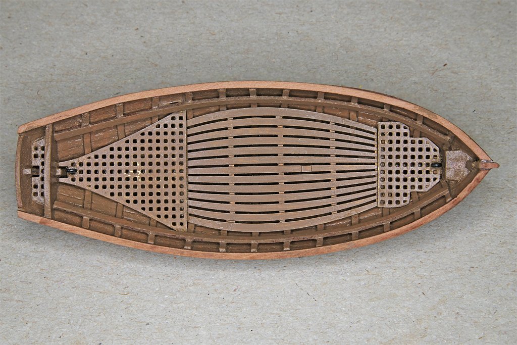
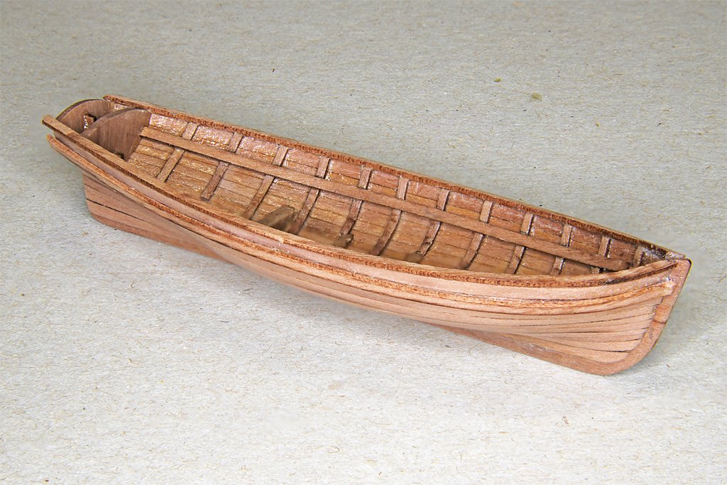
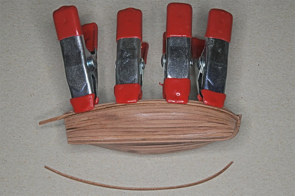
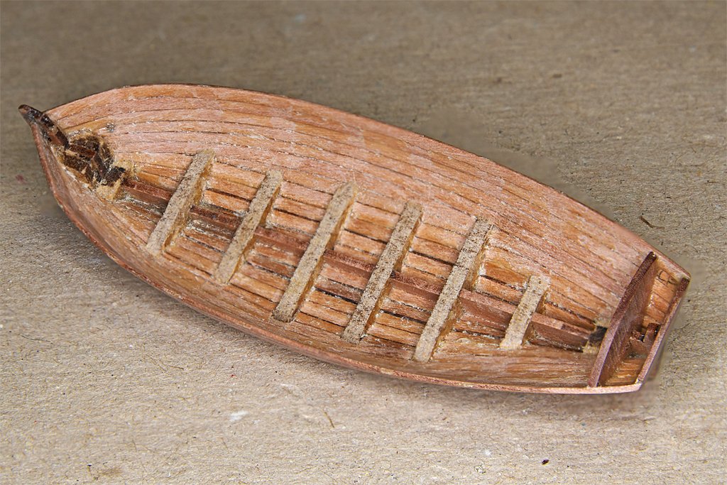
I have trimmed or removed some of the MDF bulkheads. A couple were shaped to look like ribs. This may seem rather anal since they will be hidden under the floor boards. But you can see the ribs through the cracks in the floorboards if you look at the right angle. After the seats and other parts are attached you won't be able to see much of them! I coated the inside of the hull with a clear acrylic sealer in preparation for painting. The forward deck grating has been trimmed to fit between the ribs. The edges of the center floorboards piece were beveled so it sits flat between the ribs. The small aft grating has been glued in place. It was a bit too wide fore to aft, probably because the space was a bit narrower due to the angles of the bulkhead and transom after gluing. I am procrastinating on gluing the deck pieces into place until after the inside of the hull has been painted. I jumped ahead in the instructions looking for things that can be done before painting the boat. The instructions say to use a couple of spare planks to make the wales. What spare planks? Fortunately there is a suitable narrow strip in the 1 mm pear sheet that was between the planks and seat support/ribs. The wales were bent in place on the hull using the plank bending tool. Then they were glued in place. Here I went over to the dark side and used a drop of CA gel to attach the front end of the wale to the stem. After this set I used Titebond glue to attach the rest of the strip to the hull. The Titebond takes about a minute to set up enough to hold the strips in place, and this gives time to position them. The top of the wales were positioned even with the bottom of the top planking strip. I decided to add a cap rail to the top of the planking and ribs. This isn't mentioned in the instructions, but desalgu added them when he built this kit for his Dutchess of Kingston build. Instead of cutting rowlock positions into the top plank he added thole pins to the cap rails. However May's Boats of Men-of-War says cutters had an additional plank above what was normal for other boats to increase the freeboard, and rowlock openings were cut into this plank so the oars would not ride too high and make rowing more difficult. Two extra seat support strips were used to make the cap rails. I made a bending fixture with some pins driven into a piece of scrap wood. These pieces were bent flat across the wide dimension. Again, they were wetted and shaped with the plank bending tool several times until they held their shape. Rowlock openings will be cut through the cap rail and the top plank - cutter style. Here is a photo showing the cap rails and wales after gluing in place. The aft ends will be trimmed after the glue has set.
- 54 replies
-
- 6
-
-
- 18 ft cutter
- ships boat
- (and 1 more)
-
Shipman, I share your feelings about 3D printing and resin castings. However, I do have a low end 3D resin printer, and it allows me to make detailed scale pieces that would be just about impossible any other way. For my 1:96 scale cruiser model I have printed fire strainers that are less than 4 mm long, complete with scale nuts, bolts, valves and hand wheels. The scale propellers have blades only 0.010 inch thick. Machining them out of metal would be nearly impossible because the metal will flex away from the tool. Lost wax casting doesn't work well with things that wide and thin. I have found no other way to produce these parts in exact scale. However, I do question the durability and survivability of 3D printed parts. The resin decomposes with exposure to UV so it must be painted. And the stuff is extremely fragile and breaks with the slightest touch. I try to avoid it as much as possible. I have some vacuformed hull boat kits for the cruiser model, but I haven't assembled them. I think I can do better from scratch with wood and plastic. So why not use one of these techniques since the hull will be painted anyway? I like working with wood, and the kit made the process go quicker than building from scratch (which I have done on previous builds). I am amused at your obsession with the pointed plank "fudge" in the boat hull. Are you equally concerned with the photoetch "fudge" part for the deck planking? The boat will be painted - boats were painted to protect the wood from rotting, and sometimes just because the owner/captain/crew wanted to paint them. After all, all boats have painters. And the deck planks will hide the pointed hull plank on the inside - one fudge cancels another. My purpose (and that is all that matters to me) is to make a small boat of approximately the correct scale to hang from the stern davits on the schooner model. The model would not be complete without a boat, but in reality a vessel like the schooner would probably have several boats, plus more than two anchors, etc. Virtually everything on the schooner model is just an approximation of a real vessel. I don't have the original plans (if there were any) so the entire model is guesswork. The deck and hull planks are not exactly to scale. The cannons in the kit are silly looking - nothing like the real things. I didn't make my own ropes, starting with tiny fibers and winding the ropes in alternate directions to build up a true scale rope structure. And the blocks don't have working sheaves. The paint is acrylic, which wasn't available in the early 1800s. The hull is glued together rather than using scale bolts and trenails. In fact, to be honest, there is nothing in the model (and virtually every other model ever built) that is 100% perfect scale and original materials. In that respect every model is a "fudge."
- 54 replies
-
- 4
-

-
-
- 18 ft cutter
- ships boat
- (and 1 more)
-
Shipman, Thanks for posting this information. Somehow, after decades of shaping and bending planks to fit on a hull these pre-spiled kits seem like cheating! But it does look like these kits would make nice model boats.
- 54 replies
-
- 1
-
-
- 18 ft cutter
- ships boat
- (and 1 more)
-
Part of the problem with the white pot metal (pewter?) fittings used on older models came from the cases they were mounted in. Some of the woods or finishes gave off acetic acid fumes. The cases were air tight, so the acid fumes built up and turned the metals (zinc, lead and tin) into metal acetate salt powders. The moral of the story is to use acid free materials and ventilate the cases.
-
I don't know about the period of your ship, but in modern times the anchor chain is washed with a fire hose as it comes up out of the water and then painted as it is being hauled in. It goes into the chain locker with wet paint. The part on deck dries with a shine.
-
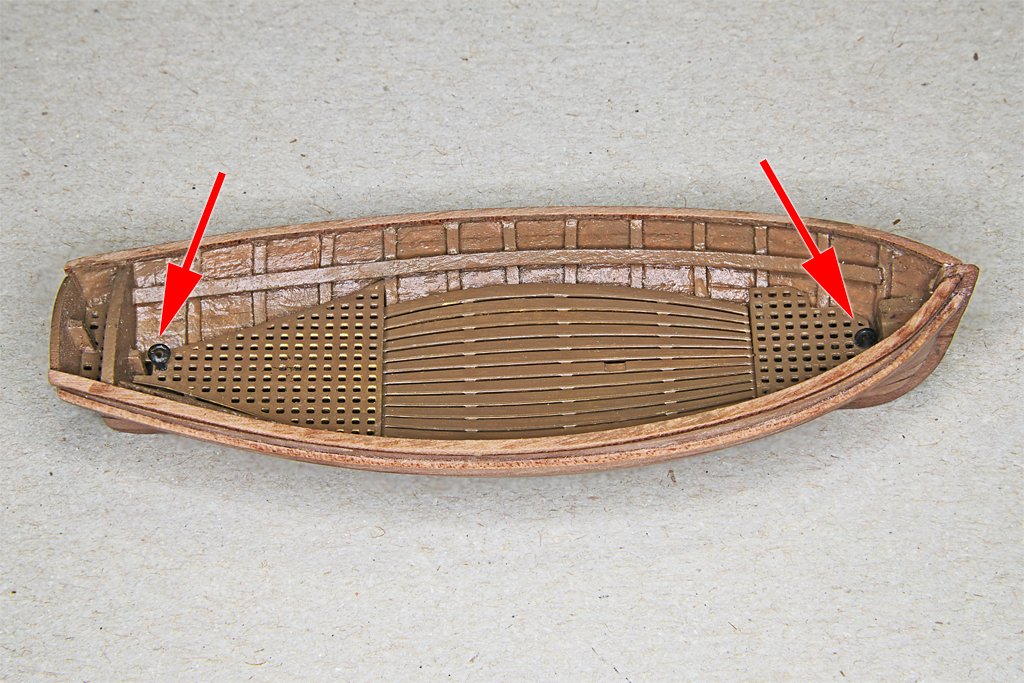
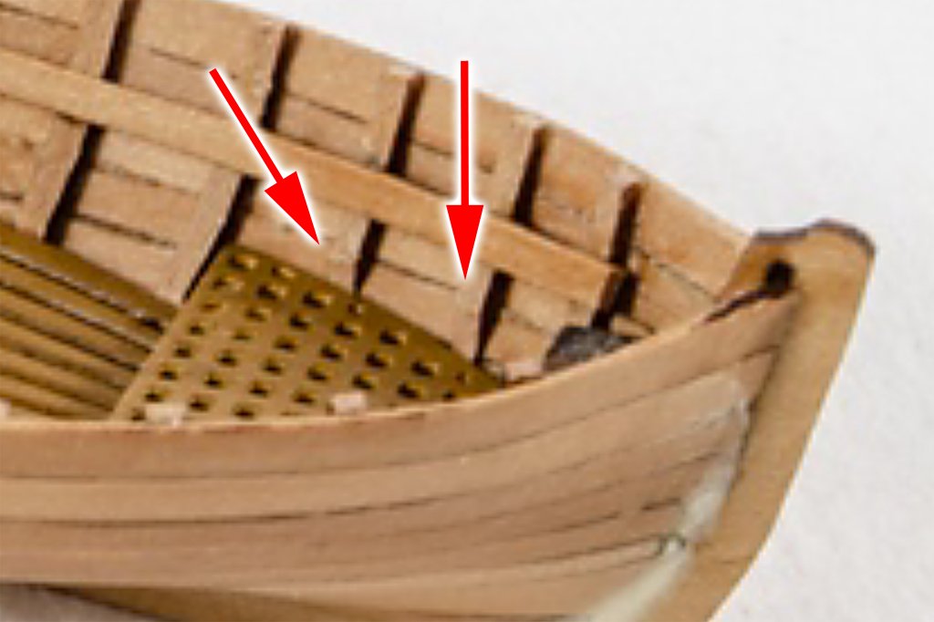
Bill, I have seen larger clinker built kits that had laser cut bulkheads and planks. with the notched bulkheads and tapered planks these assembled easily since all the guesswork had already been done by the kit designer. I haven't seen a small small boat kit but there might be one out there. If you find one let us know! I am still obsessing over how the deck pieces will fit into the hull with ribs. The small aft grating (right hand photo below, aft arrow) is supposed to fit between bulkhead C14 and the transom. But as the picture shows it just falls into the space at an angle. Looking through Boats of Men-of War I see a few boats did have this double bulkhead-transom arrangement. The after bulkhead seems to have served as a seat back. Some boats had the open space between the bulkhead and transom and some had it decked over. I will either glue a small strip to the back of bulkhead C14 to support the front edge of the grating or just plank over the opening. Working in that tight space may be challenging. I did reposition some of the ribs to get more even spacing, and I faired the forward ribs so they fit into the hull at a better angle. The center deck section fits nicely into the hull with ribs, but is curved down a bit in the center. The larger aft grating sits on top of the ribs, and just fortuitously happens to snug in behind two of the ribs that hold it in place. The bow grating is a problem! As you can see in the left hand photo above it wants to ride back on the ribs quite a distance from the bow where it is supposed to fit. In the right hand photo I have placed a bit of scrap 2 mm MDF under the grating and it sits closer to the bow. Photos in the instructions (below) seem to show the forward ribs trimmed back to allow the front grating to sit lower and more forward. I may do this if I can't figure out how to cut slits in the ribs to allow the grating to slip forward into place. The next step in the instructions is to install the seat support strips. It says to mount them about 3 mm below the top of the hull planking. I clamped the strips into the hull and bent them to shape with the planking iron. After the glue set for the seat support strips I test fitted the seat parts in the hull. I will need to adjust the seat positions after the floor pieces are installed. The center seat with the mast support should be positioned above the mast foot detail in the deck planking photo etch part. The after seat piece won't fit into the hull with the ribs installed. I knew this would happen after reading the instructions. I will cut notches for the ribs in the sides of the seats so the part will fit down onto the seat support strips. The large after seat part is made from 1 mm pear wood, and the narrow seat at the front runs across the grain. While I was removing laser char this part broke along the grain. I have glued some scrap strips on the bottom over the break. Cutting the notches for the ribs will be tricky. Plywood would have been a lot stronger. I have plenty of thin plywood so maybe I will just make another part.
- 54 replies
-
- 2
-
-
- 18 ft cutter
- ships boat
- (and 1 more)
-
Dowmer, Bill's post about clinker built cutters was good, and Craig's answer was correct - for British boats of the 1700s and later 1800s. And everyone should be happy that Vanguard also has clinker built cutters - with 3D printed hulls. https://vanguardmodels.co.uk/products/18-cutter Think about it a minute - do you really want to try to build a 3 inch (74 mm) long clinker built hull with 1.5 mm wooden planks? Even though my carvel built boat came out OK, I screwed up the plank tapering. On a large model hull a fraction of a mm difference in plank width doesn't create a problem. But when the planks are only 1.1 mm wide to start with, any errors accumulate fast!
- 54 replies
-
- 1
-
-
- 18 ft cutter
- ships boat
- (and 1 more)
-
Craig, I certainly am not an authority on small boats or cutters, but I do have W. E. May's The Boats of Men-of-War, Naval Institute Press, Annapolis, Maryland, 1999. It is mainly (entirely?) focused on British boats. It says early 1700s cutters were initially clinker built because they were made at Deal for the admiralty, and that was the tradition at Deal (pages 32, 34 and 66). Eventually any type of boat that was clinker built was called "cutter built," including boats of different types significantly different from the small cutters. But later boats were commissioned at other boat yards, and the naval yards used carvel construction (page 34). In some cases the location where the boat was to be used determined the type of construction. For use in the English Channel boats were built clinker style, but for foreign service the same type of boat was built carvel style (page 40). Some cutters were carvel built (page 66). Clinker built boats were lighter than carvel built, but they required more expensive metal hardware. By the early 1800s clinker built boats were out of favor because they were thought to be less durable and harder to repair. All boats to be used in foreign service were to be carvel built. In the early 1800s cutters were ordered to be carvel built, and cutters so built were sometimes called "jollyboats" (page 67). These were heavier than clinker built boats, and were out of favor by the mid 1800s. And so on ... All of this is just about British Royal Navy boats. In fact, small boats actually were being built elsewhere, for other uses than the Royal Navy! Really! This is why I am writing this. It really twists my tail when someone suggests all "xx" from everywhere throughout all of history were built/done in a single way. My response is to say "prove it!" My experience has been that no two ships/boats of the same type were ever built the same way in different shipyards. But I cannot prove it never happened. Cutters were clinker or carvel built, depending on when, where and who was building them. I am building this boat for a hypothetical American topsail schooner of about 1815, made somewhere on the US east coast, by some boatyard. Who knows how those boat builders made small boats?
- 54 replies
-
- 1
-
-
- 18 ft cutter
- ships boat
- (and 1 more)
-
Valeriy, You are a brave (but very experienced) man to twist the blades after they have been soldered to the hub! But I have seen your posts in other builds so I have no doubt they will turn out excellent!
-
Bill, Lapped planks (clinker or lapstrake construction) were (are) very common on small boats - and even some pretty large fishing vessels and such. I think it is just the preference of the builder or the local tradition that decides how the hulls would be planked. However, for this kit you would have to find new wood for the planking. The planks that are supplied are only enough to fill the distance from the shoulder on the bulkheads to the keel, placed edge to edge with no overlap (carvel construction). You certainly could use the kit bulkheads as the framework for lapstrake planking. The supplied 1.1 mm wide planks are too narrow (in my opinion) for lapstrake planking. You would probably want something like 1.5 to 1.6 mm wide planks, and about 0.5 mm thick.
- 54 replies
-
- 3
-
-
- 18 ft cutter
- ships boat
- (and 1 more)
-
Welcome aboard Mark!
-
Very nice gun tackles on the carronades!
-
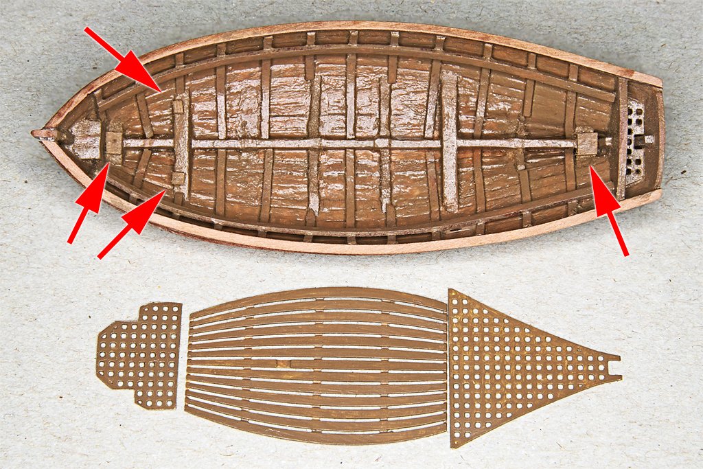
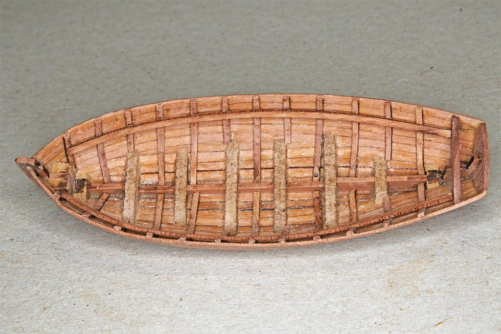
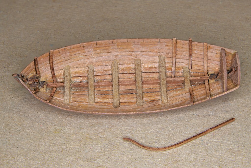
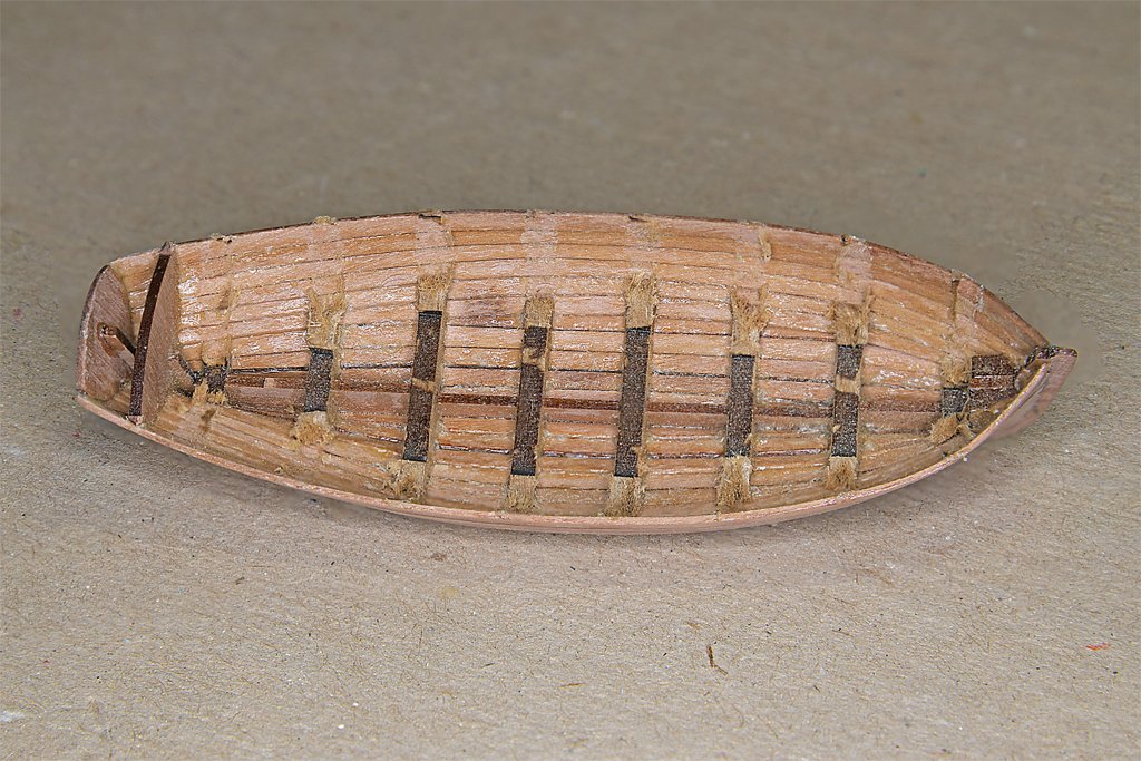
The next step in the instructions is to install the ribs inside the hull. These are laser cut 1.1 mm wide strips of the 0.6 mm thick pearwood. After reading the full instructions I realized that the floor parts will interact with the ribs. There are four photoetch brass pieces for the floors. The center floor should fit between the MDF bulkheads as shown in the left photo above. I had to shave a bit off the bulkheads (arrows) for the deck to fit between them. The photo on the right shows where the two end floors should fit at the bow and stern. These pieces do not rest on the MDF bulkhead parts, but are suspended at the sides from the planking. They probably will need some supports. The arrows on the picture at the right also show where I will install ring bolts for the boat tackle hanging from the schooner's stern davits. They will be glued into the MDF bulkhead pieces. This will require modifying the photoetch deck pieces. I think the ribs will need to be trimmed all along the edges of the floor pieces for everything to fit together. But at this point I don't know how this will be done. So I just proceeded with installing the ribs and will deal with the interferences and fits later. I wet the strips with water and used the plank bending/quilting iron to shape them to fit inside the hull. They were glued in place with Titebond glue. There was just enough of the rib strips to complete the job. I think the intent of the design was to extend the ribs down only enough for the lower ends to be hidden under the deck planks. As you can see, I extended the ribs down to the keel, and there almost wasn't enough of the strips. I had some trouble getting the strips to fit into the hull at the proper angles. The problem stems from the ribs not being faired (shaped) to the angle of the hull planking. The strips try to fit flush with the plank surfaces, and that causes them to angle inward, especially at the bow. Fortunately the Titebond glue will loosen when water is added to the joint. Of course you have to be careful here because the planks are also being held together with the glue! The decking will hide the lower ends of the ribs, but there still is some reworking needed to get better angles for these ribs. After I see how the deck parts fit I think I will use the motor tool to remove more of the MDF bulkhead material under the decking so it doesn't show between the deck planks. I also know that the after seat piece will have to be notched to fit over the ribs.
- 54 replies
-
- 6
-
-
- 18 ft cutter
- ships boat
- (and 1 more)
-
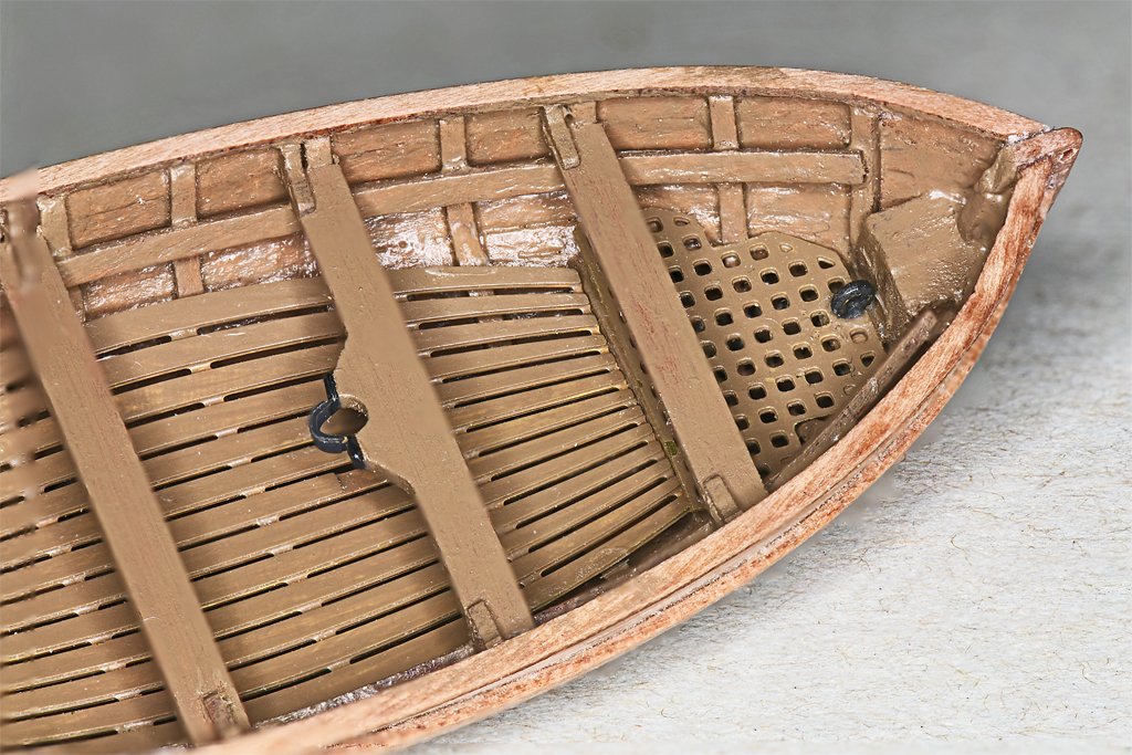
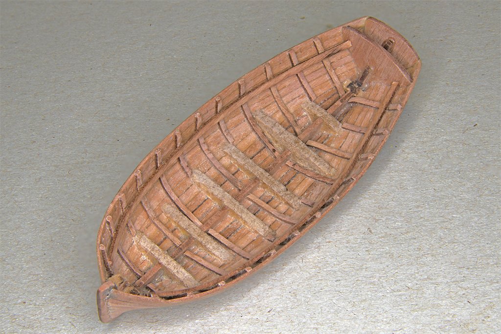
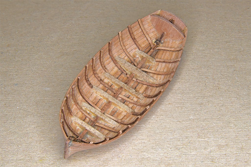
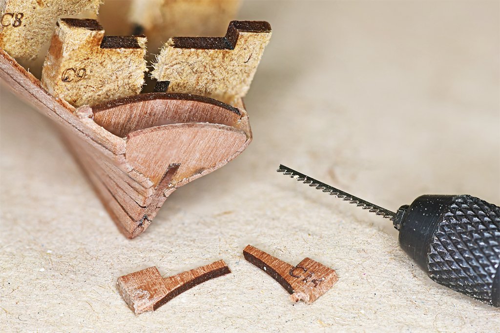
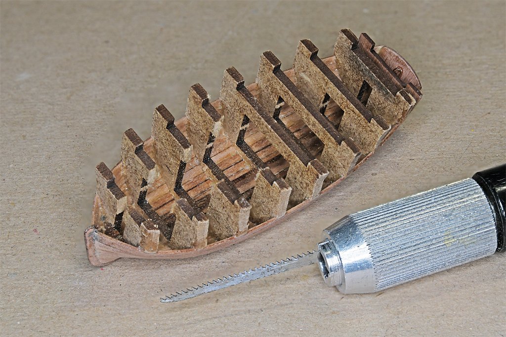
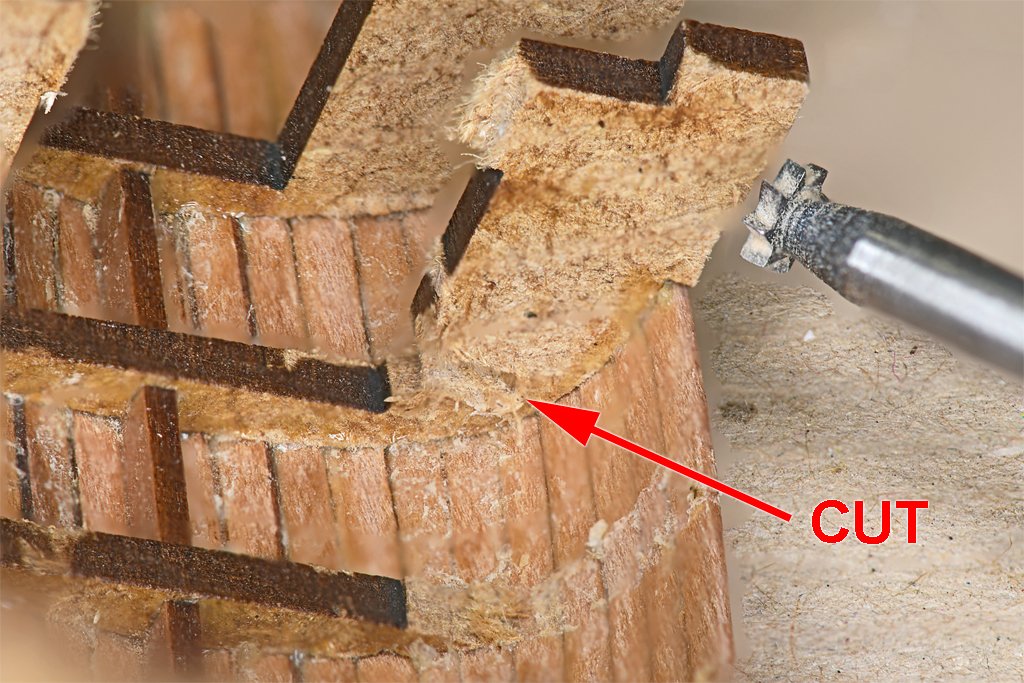
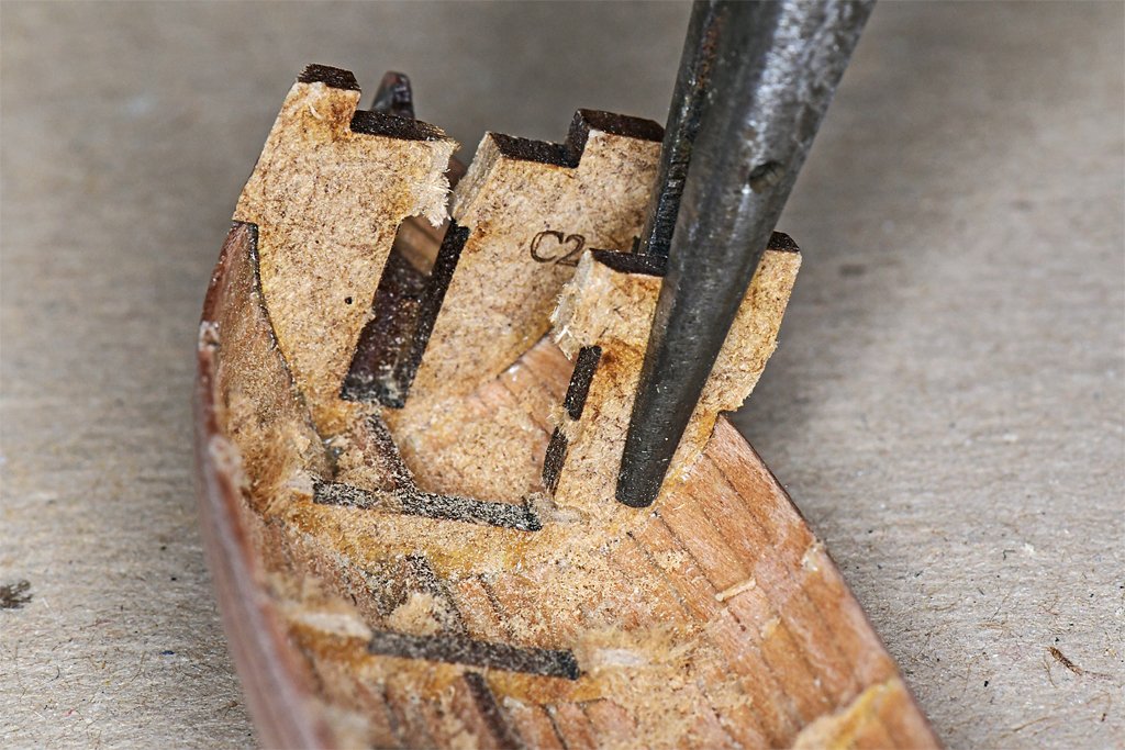
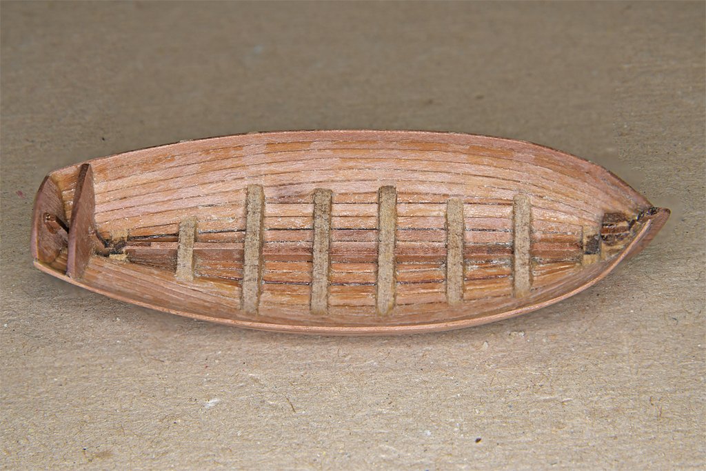
Murphy must be on vacation! I removed the bulkheads without a problem! Bulkhead C14 had a very narrow slot burned in to allow the top part with the tabs to be removed after planking was done. I used a piece of a jeweler's saw blade chucked into a small pin vise to make cuts on both sides. I deliberately broke the top of the arch before sawing so I could remove each side individually. This is the only bulkhead that will remain in the boat. I used a small "keyhole" saw blade in a handle to cut away the part of the bulkheads above the center opening. The instructions show using side cutter pliers to chop through the MDF, but I thought that would create side forces pushing outward. The saw cut through without doing that. A small cutter/saw in my motor tool was used to make a cut where the bulkhead side piece meets the bottom piece. I wanted to leave all of the bulkhead bottom part to serve as a support for the photo etch floorboard piece. This probably wasn't necessary and wasn't included in the instructions. I was just making sure ... I used pliers to twist the bulkhead pieces away from the planking. The instructions say to do this and it works as promised! The bulkhead piece was twisted gently to break the glue bond with the planks. The twisting also finished breaking the bit of MDF remaining at the cut between the side and bottom of the bulkhead. I was worried that twisting the bulkheads like this would damage the planking. This was not a problem! Here is the hull after the bulkheads were removed. It is pretty solid and holds its shape. There was glue residue and some bits of MDF remaining on the inside of the planking. I used a variety of scrapers to remove this material. Then I put a small flexible sanding disk in the motor tool and ran it at the slowest speed. There isn't much wood in the thin planks and high speed might eat through quickly. As it was the motor stalled if I pressed too hard and it took some time to clean up the interior. But it looks pretty good now! I did encounter a small problem. I tried fitting the rudder onto the transom. The rudder piece has a tab that should fit into a rectangular hole near the bottom of the transom. But when I tried to fit the tab into the hole the handle of the rudder hit the top of the transom and bulkhead C14 (the one immediately forward of the transom). It was a slight interference and filing/sanding the tops of the transom and bulkhead eliminated the interference.
- 54 replies
-
- 7
-
-
- 18 ft cutter
- ships boat
- (and 1 more)
-
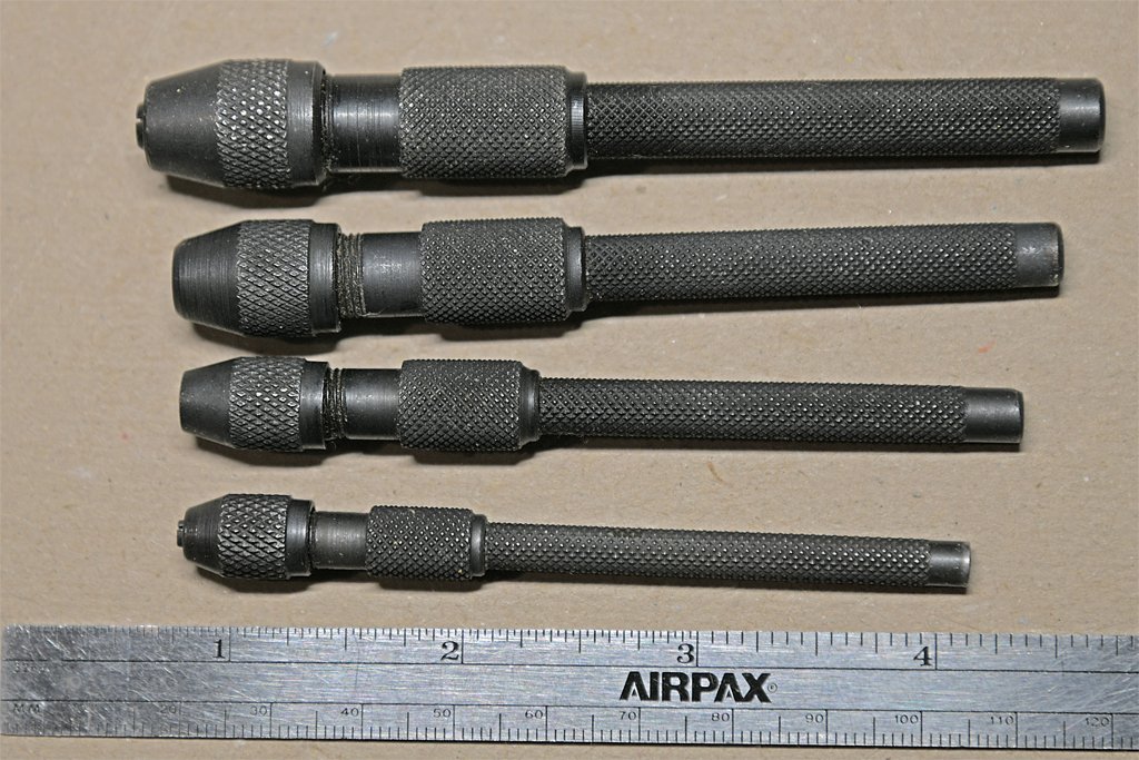
1. If you will be using a hand held pin vise DO NOT get carbide bits. They are very brittle and break with the slightest twist. These are for use in milling machines, drill presses and PC board fabrication machines. High speed steel bits are good for pin vises. Most of the bits I have seen with thick shafts and narrow cutting ends are carbide and are designed for automatic drilling machines. 2. Whatever you get, be sure it will hold the smallest bits (#80, 0.0135 inch, 0.34 mm). I have two of the types with removable collets and they will not hold the tiny bits. I bought a set of four pin vises with the "collet" as part of the body. The smallest closes down to virtually zero diameter and holds the smallest drill bits tightly. The handle is a simple knurled cylindrical shaft that can be chucked into a drill press. The handle is hollow, and allows long bits, wires, needles, whatever, to be held by the pin vise. I don't recall where I got them, but the set wasn't very expensive. Almost certainly made in China. 3. These things are useful for holding anything small. In addition to drill bits I have used them to hold needles, pieces of wire with hooks in the end to help with rigging, and short pieces of jeweler's saw blades. Here is a photo of the smallest pin vise holding a piece of a jeweler's saw. I needed to make a cut with a very narrow kerf. Having multiple pin vises means you can use one to hold the thing you are working on and another to hold the tool you are using. Or you can have multiple sizes of drill bits ready to use without changing collets. 4. The only drawback I have found with the hollow tube handle pin vises is that they do not have a finger rest on the end of the handle - just the end of the hollow tube. This is a bit uncomfortable when using a finger to press the tool as you are turning it to drill holes. I have thought about making one - perhaps adapting the rotating finger rest from one of my other pin vises that has multiple collets. Bit this hasn't been a big problem.