


Dr PR
-
Posts
2,203 -
Joined
-
Last visited
Content Type
Profiles
Forums
Gallery
Events
Everything posted by Dr PR
-
 Interesting discussion. Here is an additional "factoid." I think it was on the three masted iron ship Balclutha in San Francisco where I read that some ships sailing to San Francisco around Cape Horn would carry large round mill stones as ballast. These could be sold in California and other west coast areas because these lands were being settled and needed mills to process the locally grown wheat. But after a while the market was saturated so the mill stones would be heaved over the side as new cargo was loaded. And when the 1849 gold rush started hundreds of ships were abandoned by their crews and eventually sank. Much of the San Francisco waterfront was built over these rotting hulls. As a consequence San Francisco Bay has many mill stones scattered on the bottom.
 -
It seems to me that your water line (LWL) is a bit too low, especially at the stern. Not much, but a bit low. I am looking at Howard Chalelle's drawings of Grecian in The Search for Speed Under Sail (page 223). These "Baltimore clippers" had deep "V" shaped hulls that displaced much less water than the commercial vessels' "U" shaped hulls. This meant less buoyancy so the hulls sat deeper in the water. But it also meant they were very fast. About even with the main mast the distance from the waterline to the wales was about 2/5 the height of the wales and maybe 1/3 the height of the bulwarks. I made this same mistake on my topsail schooner build and had to go back and repaint the waterline a bit higher.
-
tmj, That is likely true. Shipyards/boatyards have their own "right way" to do things that doesn't have to be explained. When researching the Cleveland class cruisers (27 built) I discovered I sometimes could tell from photos which of the four shipyards each ship was built in. Although they were all built from the same blueprints each yard had a "better idea" and created their own unique designs and builds, often significantly different from the Navy blueprints. Some of these changes were adopted by the Navy and sent out to all the yards as revisions. I suspect no two ships were built the same, not even when laid down side by side in the same yard. Wooden ships, old and modern, were built the way the shipwrights thought they should be built. Since the MSIs were designed and constructed in yards that made fishing boats, I am sure a lot of the things the yards normally applied to fishing boats also went into the MSIs. So the blueprints left many things open for the boat builder to do as they had always done. And of course, everyone who built fishing boats knew how to apply the protective sheathing, so why bother to spell it out? However, the 300+ pages of MSI blueprints do specify a LOT of nit-picking details, like how long the threads on bolts should be, how different timbers should be joined, and how many coats of a specific type sealant should be applied. I found this same approach to design and building applied to topsail schooners (Baltimore clippers) when I researched my schooner build. Every builder and shipyard had their own way of doing things. And there were no blueprints, just a specification saying "this is what I want." And it was up to the yards to build it.
- 253 replies
-
- 4
-

-
- minesweeper
- Cape
- (and 1 more)
-
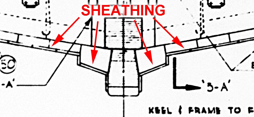
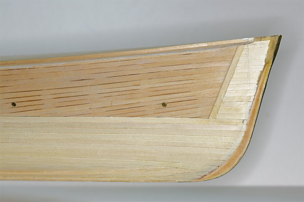
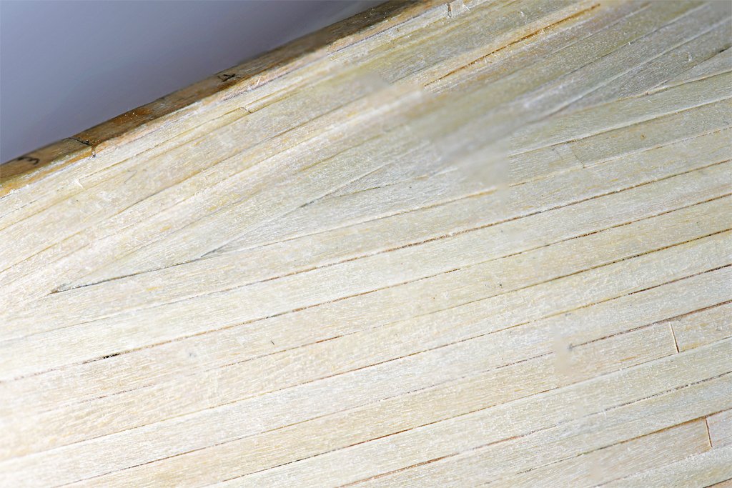
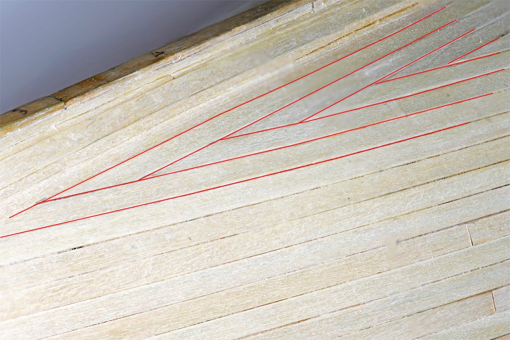
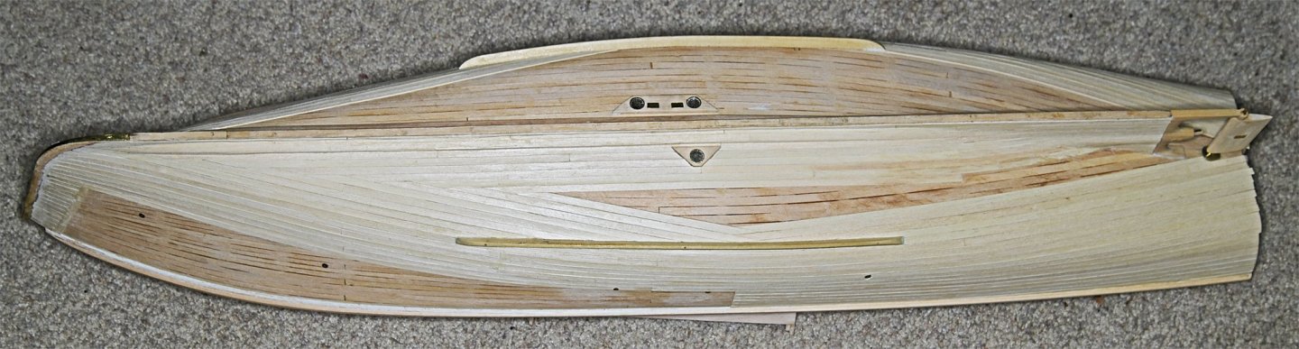
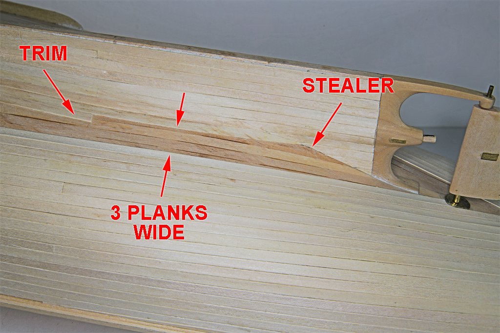
I have almost completed the sheathing on the starboard side. I am waiting to see if this works out before continuing on the port side. CAUTION! This planking pattern is speculative. The blueprints say the entire hull below the boot topping had an extra planking of 3/4 inch red oak planks that were spaced 1/4 inch apart, with nothing in the gap between them. Other than that there are no instructions how this sheathing was to be installed. As noted above these planks were not tapered at the ends. So this is my best guess (and only a guess) as to how to apply these planks! In the photo above you can see that when the planking parallel to the top of the boot topping is extended below the bilge keels it comes together at an angle. And there is planking parallel to the keel and garboard strake that also intersects the upper planking at an angle. You can see in this photo the sheathing does angle downward at the bow, just like in the photos of the modern day Cape. The lower planking has a bit of an upward curve as it comes to the bow. It was apparent that something had to give, and some of the planks must be cut at an angle to join with the others. But how? After thinking about this for a while I came up with the idea of joining them in a herringbone pattern, alternating between the upper an lower planking. Here you can see the junctions between the planking (left) with red lines to outline the herringbone pattern (right). If you look closely in the photos above you can also see I have planked the garboard strake and the keel with sheathing. But as instructed in the blueprints I didn't sheath the worm shoe at the bottom of the keel. This section of a blueprint shows how the sheathing fit around the garboard strake and keel. The more or less horizontal planks were installed first, and the vertical side trim was applied next. Cutting and fitting these pieces was tedious and tricky! The real problem is shaping up at the stern along the skeg/deadwood and stern frame (propeller and rudder frame). The blueprints show clearly that the sheathing planks on the skeg were parallel to the bottom of the keel. It was easy to fair the sheathing on the garboard strake into the sheathing above and below it, carrying the planks straight out to the stern frame. But as these planks come out onto the body of the hull they develop a significant curve (requiring wet heat for bending). The planks laid parallel to the boot topping are bending inward toward the center line near the stern. But the curvature is not as great as the planking meeting the skeg. The gap at the narrowest point (arrows) is three planks wide, so the upper and lower planking will come together nicely, except for a triangular space that will require a filler/stealer. The upper and lower planks come together at an angle, so they will have to be trimmed in a herringbone pattern like I have done at the bow. But it is a very narrow angle, requiring the planks to be cut to a sharp point. And as we all know, this is supposed to be a no-no! But I really don't know what else to do given the constraints on the sheathing planks. Is this a perfect solution? How can it be when I don't even know what it was supposed to be!? Is it a good solution? Maybe, maybe not. But it does allow me to move on past this part of the build and get on with all the complex deck houses and minesweeping gear. I have already started on the CAD drawings!
- 253 replies
-
- 6
-
-

-
- minesweeper
- Cape
- (and 1 more)
-
Very nice work. The books say Grecian was a fast ship, and the hull looks it!
-
Wefalck, I agree. I tried some wooly knitting thread, but when pulled tight it made a pretty thin chafing mat at 1:48. Maybe if it was wound in two or three layers it would work. Or roll a paper tube and wind the thread around it? Likewise, at larger scales the ordinary pipe cleaners I used would probably be too small. But I did notice some larger multi-colored pipe-cleaner-like "craft" things that were about 5 mm/1/4 inch diameter. For "crafty" people who smoke big pipes?
-
Worst Planking Job Ever
Dr PR replied to rhephner's topic in Building, Framing, Planking and plating a ships hull and deck
rhephner, As you know, wood will bend, but it has a grain that tries to straighten it back to the original shape. To get it to curve around the shape of the hull you have to "retrain" it to the new shape. Virtually every tutorial about bending wood mentions water and heat. Some people just use water and clamp the wet wood into a form with the desired curvature. Eventually the wood will adapt to the curve - I'm not sure the water has anything to do with it. Steaming wood to get it to bend is a very old technique. The heat is what does the work, and hot water or steam is used to convey the heat into the wood quickly. You also need to taper the planks to compensate for the difference in distances around the large midships bulkheads/frames and the shorter bow and stern bulkheads. The best way I have found for getting planks to form to the shape of the hull is to heat bend them on the hull. This gets all the correct curves and twists - you won't get this with an off-hull bending form. I use an inexpensive ($35) quilting iron (Mini Iron II - Clover No. 9100) as a plank bending tool. I put the plank on the hull in approximately the position it should go. Then I wet the plank with water, using a paint brush. Then the bending iron is applied to turn the water to steam and heat the plank. Quite often a single pass along the plank is enough to get the desired bend. I usually give it three passes anyway, just to be sure. After heat forming the plank It will just lay on the hull with the correct shape without clamping. Then it is easy to glue in place. This is far and away the best way to bend planks that I have seen! This link shows how I have been doing this: https://modelshipworld.com/topic/37060-uss-cape-msi-2-by-dr-pr-148-inshore-minesweeper/?do=findComment&comment=1075263 -
Downloading PDF files
Dr PR replied to popeye2sea's topic in How to use the MSW forum - **NO MODELING CONTENT**
Henry, This could be a browser problem. I'd do a Google search for problems receiving PDF files with your browser. Several years ago high-zoot programmers had a convention to discuss how to "improve" the Internet. One of the problems is that the file type (name.type) for the file names can be anything, thanks to the less than brilliant programmers who created this crap. Anyone can rename a text file type to be a picture file type, or anything else. Computers use the file type to determine which programs should open the file, but in fact, because there is no security built into the system, file types are meaningless. Hackers use this bug to plant software "bombs" that can take over programs that open the files. So the later day geniuses decided that file types would be used no more. The file type must be embedded in the file header (part of the information in the file). Returning from this convention, one of these less than brilliant programmers changed a popular email program to reject all PDF files that did not have the file type embedded in the header. And in one incredibly stupid stroke this idiot denied the program's users access to virtually all the collected wisdom in the world that was in PDF format because this new "standard" had not been implemented yet!! And, of course, most of those old files will never be updated, nor will much of the software that generated them. This is the sort of stupidity that passes for intelligence among the folks who manage the Internet and develop software, web pages and such. And it is quite possible that one of these bozos created an update for your browser that rejects old format PDF files - or any other file created before this convention of idiots. -
Chuck, Push a pin into a piece of wood. Stack thimbles on the pin until you get to the number you want to package (25?). Clip off the pin above the stack. Now to measure the number of pieces you don't have to take the time to count them. Just stack them on the pin, dump into a bag, repeat. And I would do this over a large bowl or baking pan, with the parts in the bowl/pan. That way they can't roll away.
-
Thanks Steve.
-
I rigged the port anchor buoy about the same as the starboard buoy, mainly because I couldn't think of a more reasonable way to deal with the buoy while the anchor was being fished. In this scenario after the anchor was hauled up horizontal the buoy was pulled in, tied to the forward shroud, and the rope coiled and tied in place to get it out of the way. Now I just need to add the flag.
-
Topsail schooner sail plans and rigging
Dr PR replied to Dr PR's topic in Masting, rigging and sails
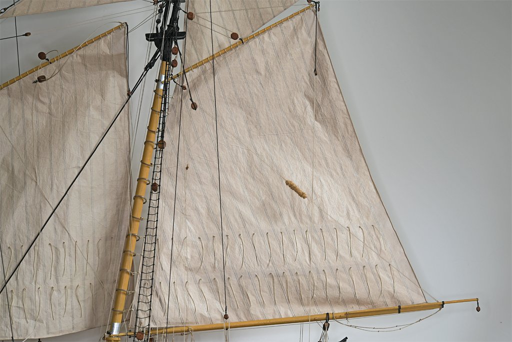
wefalck, I have seen the triangular course as well. And there is a triangular topsail (rafee topsail). The sail in the photo is flown on the windward side where it would have some effect. Because the fore staysail is also raised a full course would probably chafe against the staysail. So from a functional standpoint this makes sense. Or maybe they were just drying laundry? **** When I started this thread I naively thought there was a "way" to rig a schooner. But after finding 10 different ways to rig just the main gaff topsail I realized that if a way to rig a sail is possible someone has probably tried it! -
Topsail schooner sail plans and rigging
Dr PR replied to Dr PR's topic in Masting, rigging and sails
Just when you think you have seen it all, something new pops up. Look at the sail marked with the red arrow on this nice photo (by Tyler Fields) of the modern replica of the Lynx. What do you call this sail? It might be a studding sail, bit it isn't attached to the studding sail yard. It is attached to the course yard (spreader). Is it a "half course" as opposed to a "full course?" It might be a triangular sail.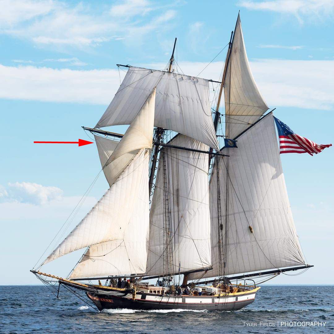
-
What Am I Missing
Dr PR replied to acaron41120's topic in Building, Framing, Planking and plating a ships hull and deck
Allen, I have a collection of rulers gathered over the ages, and it is surprising that some of them differ greatly from the rest - even the triangular "engineering" and "architecture" scales. Some are off as much a 1/8 of an inch in 12 inches (1 part in 96 or 1.042%). Good enough for grade school or making dresses, but not OK for precise measurements. I have a steel ruler marked in 100ths of an inch and it agrees exactly with a CAD created scale printed at 1:1 (viewed with a magnifying loupe). This is my "standard" ruler. When I need to measure around a curve (like the edge of a bulkhead) I cut paper strips, mark them carefully, and measure with the ruler. -
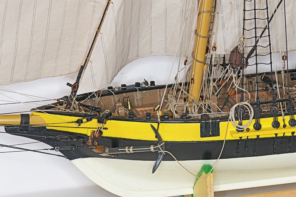
Good choice. From what I have read many American ships followed the British color scheme of black from the water line up to the band along the gun ports. This was a yellow color. They repeated the black/yellow/black pattern for each gun deck. The mast tops were painted black - probably because they had that paint on hand. This changed to black and white sometime before 1830 on some ships, and on nearly all by the 1840s. When they switched to white bands along the gun ports they started painting the mast tops white. I have never seen a comprehensive discussion of ship colors in the 1700s and up until the mid 1800s. Chapelle did write a paragraph about schooner colors in The Baltimore Clipper on page 170. Blue is one of the colors he mentions for hulls, and dark (Navy) blue would be appropriate.
-
CA (cyanoacrylate) "super glue"
Dr PR replied to Dr PR's topic in Modeling tools and Workshop Equipment
Thanks to everyone for all the tips and information. I am familiar with Bob Smith Industries. In my company's work making oceanographic instruments and some other industrial controls we special ordered custom glues specific for unusual environments (8000 psi deep ocean pressures or high temperatures). I haven't seen BSI products on the shelves around here, but I'll look again. Maybe I will try Gorilla CA - I have seen Gorilla products in stores here. **** To answer Gary's question "Is Corvallis, Oregon, particularly humid?" This is western Oregon, 36 miles from the Pacific Ocean! If the ground gets dry folks call it a drought! Some years it rains from November to May almost non stop. However, it isn't "rain" like you get in the southwest. It mostly drizzles, and what Oregonians call rain we called "sprinkles" when I grew up in Arkansas. We get only about 40 inches per year here in town, but up to 120 inches on nearby Coast Range mountains. The saving grace is that it doesn't rain much in summer and fall, and it rarely gets hot. So it never gets hot and muggy. -
I learned long ago to rig the ropes with barely enough force to pull them straight, without bending anything. This will eliminate almost all slack lines. You can permanently fix ropes in the straight shape by painting the rope with shellac or white glue (shellac for polyester and white glue for cotton and silk). This is also good for "training" lines to have a smooth curve or sag where appropriate. However, I do have this problem on my current build with lines to the fore course (spreader) yard because there are several lines lifting the yard and none pulling down. The yard rides up and the lifts and buntlines go slack. If I had rigged the course the lines to that sail would have pulled the yard down. I can probably solve this problem by weighting down the yard to stretch the lines tight and then fasten (glue) the trusses to the mast. Another option is to drill a small hole through the yard and into the mast, and push a wire or pin through to hold the yard in position.
- 354 replies
-
- 2
-
-
- Flying Fish
- Model Shipways
- (and 1 more)
-
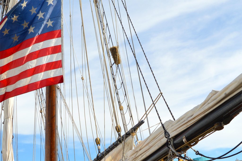
Here is a bit more progress. I have added foot ropes to the bowsprit. Apparently these ropes were called "horses" up through the end of the 1700s (in English). Then they were called "man ropes." Today to be politically correct perhaps we should call them "people ropes." Horses, manropes, people ropes - they are all silly. Obviously they are foot ropes (or footropes)! When I started investigating how these ropes were attached I found varying opinions - probably all correct for particular ships at a certain places and times. Lee's Masting and Rigging of English Ships of War says the ropes were attached to eye bolts on the sides of the bowsprit cap. But he talks about large square rigged ships of the line and doesn't belittle himself to talk about the other less important ships like schooners. But I have seen foot ropes on schooner models rigged this way. Lever's The Young Sea Officers Sheet Anchor, Marquardt's Global Schooner and Mondfeld's Historic Ship Models all say the rope was looped around the jib boom behind the bowsprit cap and lead forward to the end of the boom. This is how I have rigged it on this schooner model. The forward ends of the lines could be attached to the end of the jib boom with a cut splice or two eyes. I used two eyes. The books say that often knots were placed at intervals to give the sailors better footing. Again there are different opinions. Depending upon which author you read the knots were this type, that type or some other type. But most say overhand knots were sometimes used, and this is good enough for the model. However, bosun's mates like to tie fancy knots. Left to themselves they often tie elaborate knots to escape the boredom of life at sea, or to look busy when the bosun is looking for someone to do real work. Now I just need to train the foot ropes to hang in a smooth catenary. **** I think there are only two things left to do on the model. I am working to finish rigging the port anchor buoy. I will probably rig it like the starboard one, although it might not have been tied in the storage position until after the anchor was secured to the rail. The flag is a problem. I have a good image of the fifteen star and fifteen stripe flag used from 1795 to 1818 (the "Star Spangled Banner"). So far I have printed it only on 24 pound printer paper, and that is pretty heavy. I need to try to print it on thinner paper if I can find some suitable for my printer. I have lost my "to do" list so I think that should finish the model. But I still need to build a suitable display stand.


-
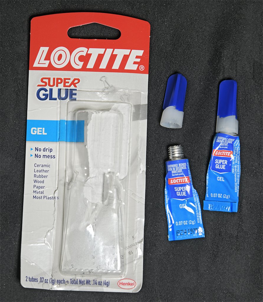
Many on the Forum seem to prefer super glue to other cements. I dislike it! I guess I am jinxed when it comes to super glue. I have purchased maybe six tubes in my lifetime. Of the first three one hardened in the tube before I ever got to use it. I used only a few drops from the other two before they became solid. The only good luck I have had with it was recently. I bought a tube of Loctite gel in a fancy applicator "bottle." This was just a plastic shell with things on the sides that squeezed an ordinary tube of glue inside. I used it between one and two dozen times before the cap became glued to the tip. While trying to get the cap off the tube began turning in the plastic shell. This twisted the tube about half way along its length, trapping about half of the remaining glue in the bottom. I eventually disassembled the thing and found the top half hardened. I poked a hole in the bottom half of the tube to get a couple more drops. Then the rest hardened. Then I bought these two tubes a couple of days ago. The instructions said to screw the end/cap pair onto the tube to puncture the thin metal diaphragm on the top of the tube. Try as I may it didn't work with the tube on the left. So I tried to puncture the diaphragm with a sharp metal point - it wouldn't puncture! The entire brand new tube was rock hard! The second tube was still pliable so the glue inside was still liquid. I tried to open the second tube and the cap would not screw on straight and puncture the diaphragm. I punctured the diaphragm with a metal point and used the end/cap from the first tube. So far I have gotten three small drops of glue from this second tube. So out of six tubes of superglue I have purchased only one gave me at least half a tube of glue before it hardened. Two were hardened before I opened them. Two more solidified shortly after I opened them. Considering the relatively high cost of this stuff, it has cost me two to three dollars per drop. That is extremely expensive! Apparently other people have had better luck and have actually been able to use super glue regularly. Does anyone ever get to use an entire tube before it hardens? What's the secret? **** Of course there is the other problem with super glue - the fumes are very irritating! Many glues have odors, but super glue is the worst! **** I have several other types of glues and these last for years after opening. I have even emptied some of the containers while the glue was still good!
-
Dan, What material are you using for rope and seizing? Every material I have used (cotton, silk, polyester) is a bit springy, and knots will try to come undone. However, silk becomes totally limp when wetted with white glue, and this prevents unwinding while the glue dries. Cotton is not quite as good, but it does lose most of its springiness when wet. Polyester rope is very springy, and knots will come untied if they aren't fixed with some type of glue. Unfortunately, the only glue I have found that will stick to polyester is CA (cyanoacrylate, super glue), and I am not sure just how good that bond is. White glue will not stick to polyester! I glue the larger rope strands together with a small drop of CA and then wrap the seizing, with a bit of white glue after the seizing is done to hold it. I normally dilute the white glue 1:1 with water, but I have also used about 70% glue and 30% water.
-
One of the details I wanted to add to the model was the "baggywrinkles" (baggywinkles, chafing mats) on the main boom lifts. I posted how I made these from pipe cleaners in this link: https://modelshipworld.com/topic/38184-chafing-mats-or-service-on-lines/?do=findComment&comment=1100130 Here are some photos of the finished part in place on the main boom topping lift. I had to unhook the standing part of the lift runner tackle from an eye bolt on deck to give the lift enough slack to wrap into the pipe cleaner coil. Then the tackle was hooked back to the eye bolt to pull the lift taut. The eye bolt is close to the bulwark so I had to use a small dentist's mirror to look down between the deck house and the bulwark to see the hook and eye. As I slowly withdrew the mirror the end of the handle caught on something (fore gaff vangs?). There was a slight tug and then "pop." Another plastic hook broke - on the fore gaff peak halliard upper block. You can see the block hanging down over the gaff at the upper left of the last photo. One step forward, one step back!


-
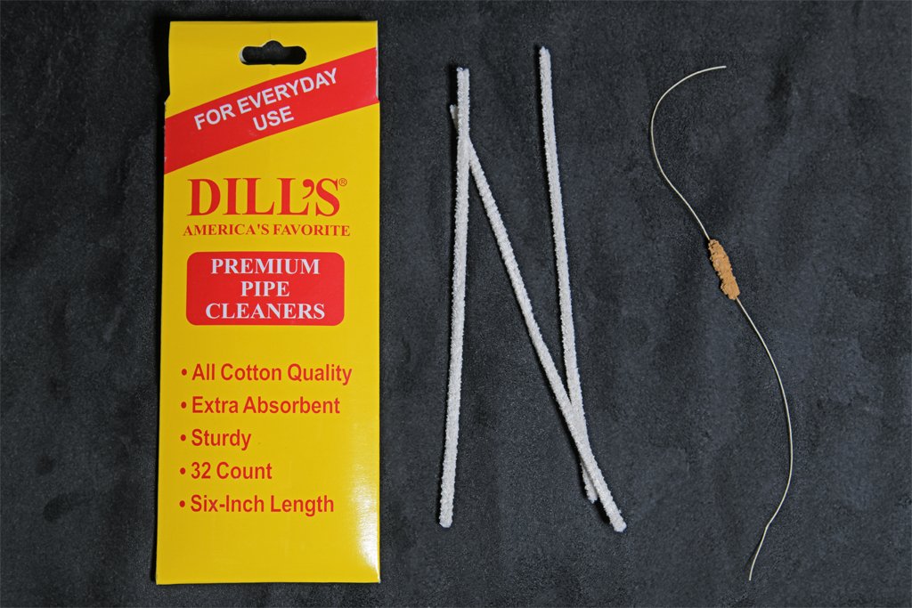
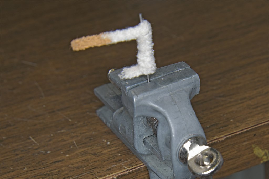
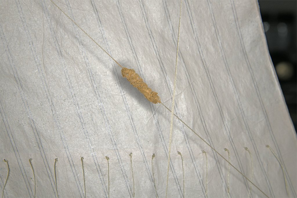
Baggywrinkles revisited. I looked at "fuzzy threads" for knitting at a local store, and they have very little bulk. I think if they were wrapped around a rope they wouldn't make much of a bundle. Then I got the idea to use one of my standard tools/building materials - pipe cleaners! I don't smoke, but I have had this package of pipe cleaners in my modeling kit for decades. They are handy for cleaning out small orifices and such. First I clamped a small drill bit into a vise. Then I wound the pipe cleaner around it tightly, leaving short "handles" at each end. Here you can see I was also experimenting with coloring the mat. The pipe cleaner material is cotton, and cotton absorbs water. I dabbed on some acrylic paint to give it the color of "used rags." The paint soaked up nicely. I am adding these after the boom lifts were already rigged. The trick here is to pull the spirals of the mat open. This allows the rope to be wrapped into the gap between spirals. But that means the rope must hang loose while you are wrapping it into the mat. The standing part of the boom lift running tackle is hooked to a ring bolt on deck. The lift wasn't installed tightly so the hook came loose easily. This allowed the lift line to be wrapped around the mat. After it was in place I cut off the "handles" and touched up the paint. Here is a photo (left below) of the baggywrinkle on the model's boom lift. The photo on the right is a mat on the replica schooner Lynx.
- 15 replies
-
- 5
-

-
-
- baggy winkle
- service
- (and 2 more)
-
Carriage Gun Rigging
Dr PR replied to Dr PR's topic in Discussion for a Ship's Deck Furniture, Guns, boats and other Fittings
Here is a drawing from Ordnance Instructions for the Unites States Navy (1860). It shows the method of pointing a gun at an angle to the centerline of the ship. For the big lumbering square rigged ships of the line what wefalck said is probably true. But there are accounts of smaller, more maneuverable vessels like schooners pulling up off the quarter and out of the firing field of larger ships and blasting away at them. In this case angling the guns toward the target would be useful. Pivot guns apparently were often used this way. In any case the Navy seems to have thought it would be useful to train gun crews to point their guns at different angles.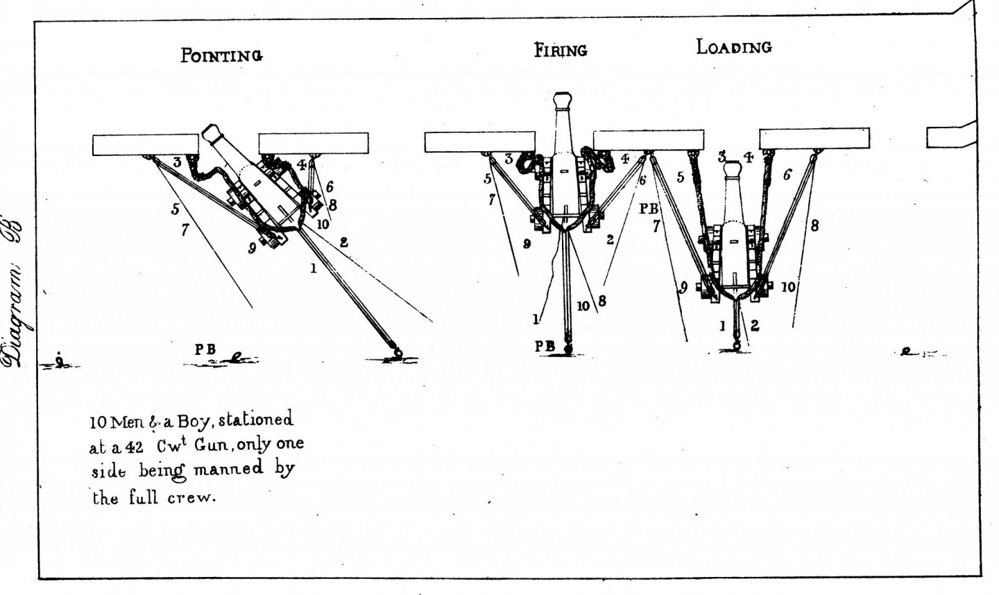
-
Some wooden hull vessels had a thin layer of oak sheathing applied over the normal hull planks. The sheathing consisted of planks attached to the hull to protect the hull in places where it could be damaged by objects being lowered/raised over the side. This sheathing was replaced when it was damaged. In two cases I know of the planks were not tapered. In one case the entire underwater hull was covered with thin sheathing, and the planks were not tapered. Does anyone have any information about how these planks were applied? What pattern? How do you plank a hull without tapering the planks?


