
MORE HANDBOOKS ARE ON THEIR WAY! We will let you know when they get here.
×


Dr PR
-
Posts
2,338 -
Joined
-
Last visited
Content Type
Profiles
Forums
Gallery
Events
Everything posted by Dr PR
-
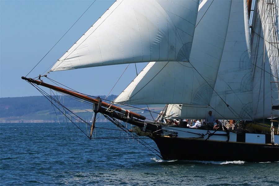
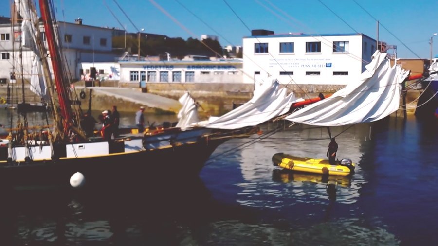
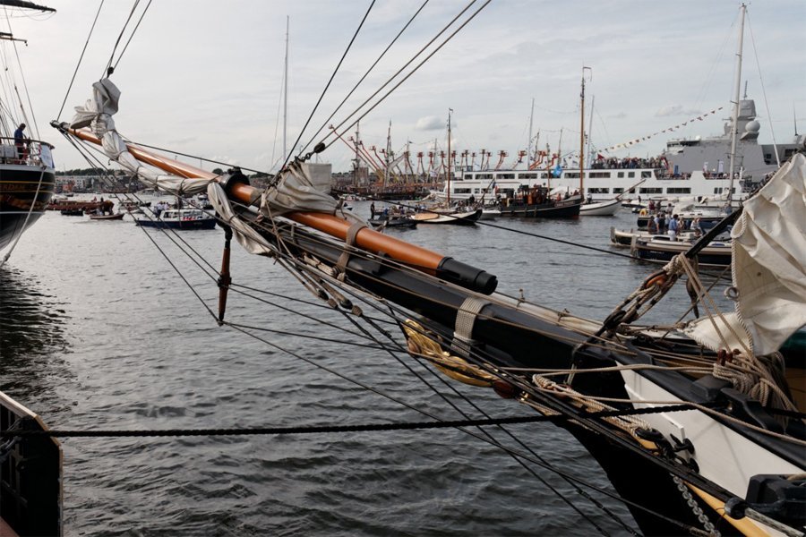
Thanks for the replies. Hauling the traveller back to the bowsprit cap to make it easier to handle the sail makes sense. But ... I have seen photos of vessels that have a traveller but do not use it when lowering the sails. Here are some photos of the modern La Recouvrance topsail schooner. First a clear shot of the outer jib and traveller. It appears that the outer jib stay also serves as the outhaul. The vessel also has a jib and a fore staysail. Here is a shot of the fore sails lowered: The dolphin striker (martingale) is visible, and the traveller clearly hasn't been hauled back to the bowsprit cap. Finally a photo of the furled sails. The traveller is still near the forward end of the jib boom. Why have a traveller if you don't use it? Many modern schooners do not have a traveller for the jib(s). So I was wondering how common it was in the past.
-
I am curious as to how common it was for vessels to have a traveller on the jib boom for the jib/jibstay? Lever, Biddlecombe and Lees describe how travellers were constructed and how sails were rigged to them. But many models do not show a traveller, and photos of modern vessels often do not show a traveller. The typical traveller was a ring that fit loosely around the jib boom (or perhaps the flying jib boom) and was free to slide fore and aft along the boom. The jib stay led to the traveller and the jib sail tack attached to the traveller. Inhauls and outhauls moved the traveller along the boom to position the foot of the sail. Note: This is a simplified description. The jib stay could also serve as the outhaul. Also, there were other types of travellers used elsewhere on ships. What was the traveller used for? Obviously it changed the position of the tack of the sail along the boom. But why? Searching this forum for "traveller" revealed opinions that it could be used to reposition the sail to gain best advantage of the wind. But some people say it was just a convenience feature to allow the jib to be hauled back to the bowsprit cap to make it easier to reef the sail without climbing out to the end of the jib boom. Since many vessels do not have a traveller, just how common were they? I am especially interested in topsail schooners, but apparently travellers were used on all types and sizes of vessels.
-
Kev, I see a problem with your sketch in post #6. If the fall of the boom sheet was secured to a cleat on the boom, and the boom was swung overboard, you wouldn't be able to reach the boom to untie the sheet. I think in a small rig like a long boat you probably would need only two single blocks , and the fall would be secured to a cleat on the rail or bulwark. It was common to secure the gaff sail sheet to a cleat on the boom near the boom jaws where it was always accessible. On larger rigs the sheet attached to a two block tackle that was attached to the jaws of the boom and the fall to a cleat on the boom.
-
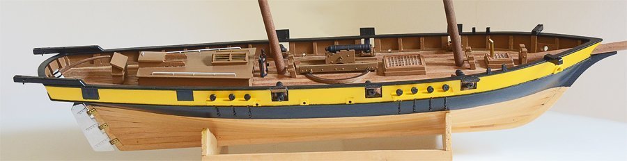
 I had another thought on this subject. The variable camber design was not limited to ancient vessels. The (relatively) modern barrelback runabouts of the early 1900s were designed with a drastically different camber from bow to stern.
 -
Terry, Thanks for the drawings - you saved me the trouble! They illustrate the ideas perfectly. And they show quite clearly that with a constant camber deck the resulting "rail sheer line" where the deck and hull surfaces join is a smooth fair curve. There is a potential problem with the "saddle shaped" deck as shown in your drawing. Of course the curvatures are quite exaggerated, but even with milder curvatures there would be a problem laying constant width wooden deck planks on this surface. If they were placed side by side at the center of the surface (longitudinal and transverse center) they would splay apart at the ends. But this would be a problem only if the individual deck planks ran the full length of the deck. In practice the planks were much shorter, and each run would be created with multiple planks. This would make it easy to bend the planks to the curvature of the deck surface. I have walked the decks of several ships built this way and the plank curvatures are so small they aren't noticeable. In steel hulled vessels the deck plates were cut to fit the curvature.
-
Caarles, I do not follow your description in post #29. In my perspective drawing in post #24, there is no incidence of the center of any of the red deck beams coincident with the black curve. There are no cases where the red camber lines, the red vertical lines and the black curve intersect. The drawing shows the case where the center of the deck camber curves intersect the straight green longitudinal "sheer line" at the point where the vertical red lines intersect the green line. The black line is just the coincidental intersection of the deck surface with the hull sides (not shown) projected upon the vertical centerline plane (not shown). It would be possible to create a different deck surface using the same constant camber deck beam curves just by lowering each camber curve to where the center point of the camber curves is on the black curve where the vertical red lines intersect the black curve. In this case the black curve would be the centerline sheer line of the deck (modern usage of the term sheer line). This deck would be "saddle shaped."
-
Tom, Excellent presentation! And I certainly agree that modern construction methods are different from those used in the past, and cannot be used for accurate reconstruction of ancient ships. After all, shipbuilding has progressed by learning from mistakes of the past. I wasn't trying to say older ships were constructed with constant deck camber. I just disagree with those who say they couldn't have been built with constant camber. The difference between the "constant camber" method and the "variable camber" method described in your post is interesting. It all depends upon which "sheer" line is the controlling factor. In the constant camber method the "sheer line" is the longitudinal (fore-aft) curvature of the deck at the centerline (crown sheer line). All transverse (side to side) deck beams are positioned with their top center on this centerline sheer line. The location of the line at the intersection of the deck surface and the hull surface is not predetermined, and is just the result of the shape of the two surfaces. Likewise, the vertical distance between the centerline sheer line and the hull-deck intersection line is coincidental. In the variable camber method an arbitrary "sheer line" (rail sheer line) where the deck surface and hull surface intersect is drawn on the profile plan. Another line is drawn for the curvature of the deck at the centerline (crown). The vertical distance between these two lines determines the curvature of the camber for each deck beam. The curvature for each deck beam would have to be calculated. I have to wonder why anyone would have used the variable camber method? It is a lot more trouble to produce and the resulting deck would be less "fair" (could be wavy) and not better structurally than the simpler constant camber method. My guess is that ship designers had not yet developed the drafting methods necessary to determine the intersection of the deck and hull side for the sheer plan.
-
Jaeger, No apology necessary. I have seen the term "camber" used for both the longitudinal )fore-aft) curvature of the deck and the transverse (side to side) curvature. I have also seen the term "sheer" used for the longitudinal curvature of the deck at the centerline (the modern use of the word) and for the curvature of elements on the sides of hulls (sheer strake) and the line where the deck intersects the hull sides. Unfortunately, many people are familiar with only one use of a word and assume it has the same meaning for everyone, everywhere and at all times. I have also seen plans showing the fore part of the deck near the hawse openings angled down (but not the other decks). I assume (but do not know for sure) this is to cause water coming in the hawse openings to be confined to the bow area. But this downward dip can be created with constant camber deck beams. The centers of the beams just have to follow a downward curve of the centerline sheer line toward the bow.
-
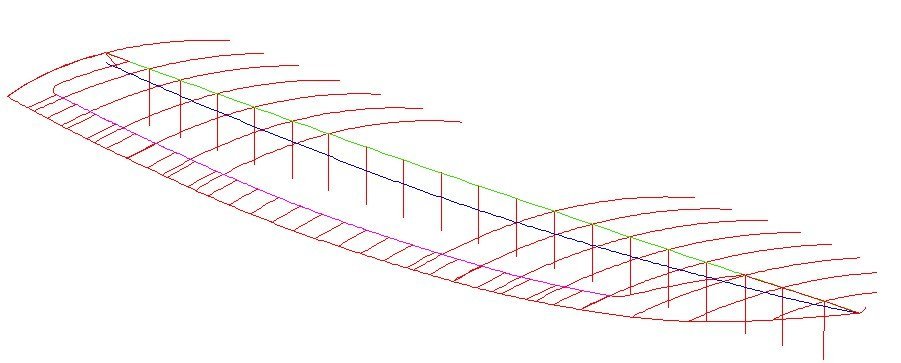
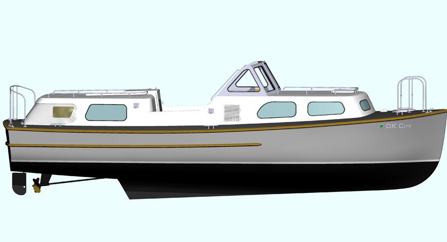
I have read through this thread several times and most of it makes no sense at all. There are too many undefined terms, ambiguous wording and simply irrational statements. It seems several people have said you cannot build a "fair" deck if all the deck beams have the same camber. I assume "fair" means smooth and not wavy, as in a smooth curve or surface. However, virtually all modern ships are built this way. This image shows the curvature (camber) of the transverse (side to side) deck beams (red). They all have the same curvature or camber. The green line from bow to stern is the centerline along the deck surface. The center point of each red transverse deck frame is positioned on the green centerline. The black line is the curve of the deck edge from bow to stern, as shown on profile views. This drawing shows quite well that anyone saying you cannot build a "fair" deck using the same camber at all stations (or deck beams) doesn't know what he is talking about. Actually, the deck surface is just a section of a cylinder, like a pipe, where the diameter (curvature) is the same all along the length of the cylinder. This is an image of the actual boat. It is a 40 foot personnel boat used by the US Navy for the last half of the 20th century. Note that the curvature of the hull where it joins the deck surface is "fair" - not wavy. The entire deck surface and hull surfaces are "fair." The deck does not curve down into "swales" at the bow and stern. Another example of a model of a 19th century wooden ship constructed with the same deck curvature (camber) at every frame can be found in this post: https://modelshipworld.com/topic/19611-albatros-by-dr-pr-mantua-scale-148-revenue-cutter-kitbash-about-1815/?do=findComment&comment=603771 In this case the deck has sheer (curvature along the longitudinal direction). The deck surface approximates a hyperbolic section, although in this instance it isn't an actual mathematical hyperbolic surface. It resembles a saddle surface, or the surface of a doughnut hole, where the deck curves downward from the centerline in the transverse (side to side) direction (camber), and curves upward from midships in the longitudinal (lengthwise) direction (sheer). The line where the curved deck surface intersects the molded surface of the hull is not wavy, but is "fair," and the deck surface does not dive down to a lower level at bow or stern. I am extremely familiar with the construction of the Cleveland class cruisers of World War II, having studied thousands of blueprints for 14 years to build a detailed CAD model of one of these ships, and I can assure you that these ships were constructed with the same deck camber at every frame on the main deck and most higher weather decks: https://modelshipworld.com/topic/19321-uss-oklahoma-city-clg-5-1971-3d-cad-model/?do=findComment&comment=590447 I have given examples of ships that were built with the same transverse curvature (camber) at each deck beam/frame, in cases where the vessel had no sheer and where it did have sheer. In each case the lines of the deck and hull were "fair." And in no case does the deck curve down (longitudinally) at bow or stern. Now can anyone explain why a ship built in ANY period could not have fair lines if all deck beams (in the same deck) had the same camber? NOTE: If you do, please define every term you use so we have a chance of understanding what you say. Otherwise it will just be more incomprehensible gibberish.
-
Allan, Thank you very much! I thought about doing what you did, but I don't have enough information about individual English ship hull and mast dimensions to get any meaningful results. I was pretty sure Lees was using what some authors call "measured length" from the foot to the top. But quite a few authors (and rules) use the hounded length, so I wasn't certain. I am using Lees' rules for rigging to determine rope sizes. I figure that regardless of the type of ship and ship size the relationship of mast diameter to rope diameter/circumference was probably about the same for all ships. Schooners typically had smaller mast diameters than did full square rigged ships, but the mast diameter should still serve to determine rope sizes. Small boat rigging is another thing!
-
Allan, You are correct - Lees does give detailed descriptions of the "length" of the main mast relative to hull dimensions on page 183, and I have no doubt that he researched this well. But what "mast length" is he specifying? I did see where he was using a length measured from the step on the keel, or the foot of the mast. But I have read through the book several times now and cannot discover if his mast length is the hounded length (from the foot to the hounds - cross trees) or the "measured length" from the foot to the top (top of the top cap) - the actual length of the entire pole or mast structure. So the question is whether his "mast length" includes the top (measured length) or does not (hounded length). Since mast diameter and spar dimensions are usually based upon "mast length" and rigging diameter/circumference is based upon mast diameter, virtually every dimension in the masts and rigging depend upon this question. Lees says the mast head length varied over time from 3.75 inches to 6 inches per yard of main mast length, or from 10% to 16.7% of the mast length. The difference between hounded length and measured length was 10% to 16.7% of the "mast length" and this will give proportionate differences to the calculations of everything else in the masting and rigging. This is a possible error of 1 in 6 to 1 in 10 in all calculations if we assume one mast length and it was actually the other he was talking about. However, he does give the diameters of all parts of the mast from the foot to the top on page 2, and I suspect he is using the measured length. But it would have been nice if he had stated unambiguously what he meant by "mast length." As I said, Lees book is a valuable reference, but this one omission greatly reduces it's reliability for mast and rigging dimensions. But Lees certainly isn't the only author to make an important omission, assuming that the reader will know what the author meant!
-
Mark, You are right, I should have checked the 0.166 value with other formulae. The stay diameter I calculated did seem rather small! Using a main mast diameter of 24 inches here are the main stay calculations. Mondfeld says the thickness (diameter) of the main stay should be 0.166 x mast diameter. (Note: my error above. Mondfeld is talking about stay diameter, not circumference) 24 x 0.166 = 3.984 inches Circumference would be diameter x pi (3.14159) 3.984 x 3.14159 = 12.516 inch circumference Lees says something (undefined) is 1/2 the mast diameter. Assuming he meant circumference, 24/2 = 12 inch circumference So there is a 4% difference between Lees and Mondfeld. For modeling purposes in all but the very largest scales this difference is insignificant. Both Lees and Mondfeld give data for large three masted square riggers, but it is all useless for schooners and other fore and aft rigged vessels. Some of the difference between Lees and Mondfeld lies in slight differences in calculations for mast length and diameter. Lees' (The Masting and Rigging of English Ships of War 1625 - 1860) calculations are specific for full scale English warships and Mondfeld's (Historic Ship Models) are more general and apply to a range of warship and commercial vessel models. Comparing them is like comparing apples and oranges. **** Everyone raves about Lees but all through the book he fails to say what he bases his dimensions on. All mast and spar dimensions are based upon a hull length or beam, but he doesn't say if the hull length is the Line of Flotation, distance between perpendiculars, or length on deck. All three different values are used by other authors, and they usually say which they use. The difference between these lengths is significant. We are supposed to guess what Lees is talking about? Furthermore, although he does define the "hounds length" he doesn't say what the "hounded length" is that mast dimensions are often based upon - but this is common to most authors. We are just supposed to know if it is to the top of the hounds, the bottom, and whether the length is from the foot of the mast or the partners, or something else entirely. Underhill is the only author I have found who says explicitly the the "hounds" is the flat the cross trees rest on, and the hounded length is from the foot (the very bottom of the mast) to the hounds. Lees also used the "length of the mast" but never says if it is the measured length, hounded length, deck to top or deck to hounds. All four lengths are used by other authors in different periods and they are significantly different. Again, are we supposed to read his mind? There are other places where he fails to define the basis for his statements. We are just supposed to know what he means I guess, and this is VERY frustrating to someone who doesn't already know all the answers. I have spent many hours doing calculations based upon the representative tables to back calculate to try to figure out what he is talking about! These errors are characteristic of someone who is functionally illiterate - incapable of understanding how to communicate the things he knows to people who do not already know. But this is a common characteristic of many authors. And a common problem I see on this forum is that different people assume they know what he is talking about without realizing their assumptions are just one of several possibilities. So they make pronouncements based upon their interpretations that often are questionable. **** Having said this, I do think Lees is an excellent reference. His drawings are superb and he gives a lot of actual ship data for English square riggers. But you have to do a lot of reading between the lines to figure out what he really is trying to say. For other nationalities and types of rigs you must look elsewhere. And as for statements that Mondfeld's (Peterson's, etc.) books are full of errors, these are always unsubstantiated. Rarely does anyone say what the errors are, and in some cases the criticism is based upon knowledge of a single vessel that differs from the author's description of another vessel. One thing I am certain of is that no two ships were exactly alike, and even a particular ship may have changed over time. And it is a fact that the records for historical ships are almost always incomplete, so a lot of guesswork is necessary.
-
ah100m is correct about the circumference error in Mondfeld's tables on rigging size. Everything is based upon the mast diameter, but the resulting rope sizes often are given in circumference! The relationship is the main stay circumference is 0.166 the diameter of the mast at the partners (at the deck). I am sure this confuses all novice modelers - it had me going in circles for a while! CORRECTION: It certainly is confusing, and tripped me up again! Mondfeld says the thickness of the stay is 0.166 (or 16.6%) of the mast diameter. Corrections below are in bold type. Rope circumferences are then given as percentages of the main stay circumference ( or the fore stay for two masted fore topsail schooners). This is common in every text I have seen, going back into the 1700s. But you must use the same units of measure (inches, centimeters, etc.). So if the mast diameter is in inches the circumference will be in inches. And if you really want to get picky, remember English feet were not the same as French, Dutch or Swedish feet (before they changed to the metric system). The differences are small and can be ignored for model rigging diameters/circumferences. However, for wire rope that began appearing in the last half of the 1800s the formulas are different - basically about 33% of the rope circumference as Mondfeld says. But this is just an approximation. Circumference = pi x diameter, or C = 3.14159 x d. So the diameter of the stay is the stay circumference divided by pi (3.14159): Mondfeld says mast diameter x 0.166 = stay circumference thickness (diameter) stay circumference = stay diameter x pi. stay diameter = (mast diameter x 0.166)/3.14159 = mast diameter x 0.0528 So the stay diameter is about 16.6% of the mast diameter. For a 24 inch diameter mast the stay will be about 4 inch diameter. Since model rope and thread sizes are usually given in diameters it is best to calculate the stay diameter and work from that. After you get the stay diameter the percentage ratios in Mondfeld's tables apply to all other rigging diameters. However, there are other rules that give slightly different results, depending upon nationality and period. And almost none of these rules apply to schooners and other fore and aft rigged vessels. **** I don't know that there are any outright errors in what Mondfeld says. He gives general rules for different periods and nationalities that I am certain were right for some vessels. But if there is anything I have learned it is that no rule applies all of the time for any period or nationality. A great deal of leeway was given to ship builders, owners and Captains for how a ship was constructed and rigged, and it could change with time. It is certain that some vessels were built and rigged differently from what Mondfeld shows, but since no two vessels were ever exactly alike, this is not Mondfeld's error. Just take what he says with a grain of salt, and if you cannot find accurate period plans for the ship you are building, Mondfeld's "rules" are as good as any other. I have compiled just about all the rules I can find in the spreadsheet in the discussion in this link about topsail schooner rigging (post #57). The spreadsheet compares the different rules and shows the slight differences. Most of the rules are for full rigged ships but there are some for schooners. Then a separate section calculates the sizes of ropes for schooner rigging based upon a mast size you provide. The thread also gives definitions of sail and rigging terminology, and the basis for calculating many of the dimensions of ships.
-
Druxey, Thanks. That is what I suspected, and enlarging the image of the foc's'le I can see a seat of ease port and starboard aft of the catheads. No covers or "closets". Not much more than a pissdale with a seat.
-
Thanks for the info. Chapelle's "History of American Sailing Ships" also shows a four-holer in the head of the Bainbridge in Figure 19 (page 123), and possibly "water closets" at the stern. I suspect that every ship that had a head also had seats of ease in the heads. But what about vessels that had no head? The drawing of the Subtle (1808) on page 235 shows cabins or water closets at the stern. The vessel was 78 feet length on deck and 139 tons. The Plate VIII (after page205) of the Joe Lane and the drawing on page 215 shows low stern water closets and lockers at the stern and more substantial two-holer water closets port and starboard just aft of the fo'c'sle deck. Joe Lane was a relatively large revenue cutter of 1851, 100 feet at the load water line and 153 tons. The Wawona of 1897 had similar facilities. I suspect most/all vessels of about 100 tons or greater that did not have a head would have had similar water closet accommodations, but very few drawings depict them.
-
George, Thanks. I know that some schooners had similar "closets" at the stern, and at least one had something like this near the bow, port and starboard. But these were relatively large vessels (greater than 100 feet between perps). For smaller vessels I am inclined to agree with Wefalk about the "gold buckets." I have read Simmon's thesis a couple of times to learn more about the subject. My favorite part is on pages 96-97 where a seaman was punished for painting an "uncaulked seam." It is hard to keep a straight face when pondering this subject. The "Ingrid and Other Studies" paperback sells for $137.05 on Amazon. That's a lot of bread for a short article about heads.
-
Yes, it was important to choose the lee side! I thought of the bucket idea and I am sure it was used on some ships. The "honey bucket" was in use in many households until the advent of running water and flush toilets. It would be "normal" to use them on ships.
-
John, It would help if you could post a photo of a gun and carriage, showing the quoin area. Carriages had a support piece (stool bed) for the quion that rested on the rear axle tree, or sometimes extended over both axle trees. Maybe your carriages have this support but do not have the quoin? If so all you need to do is add a quoin to set the gun elevation.
-
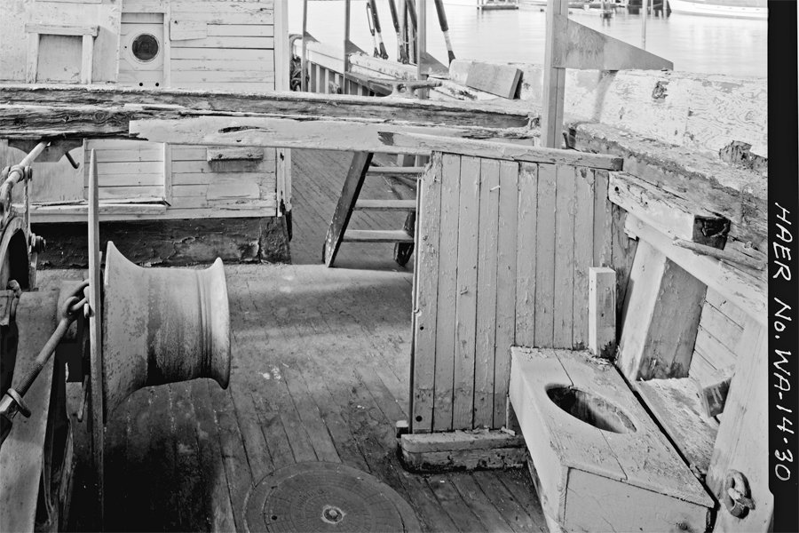
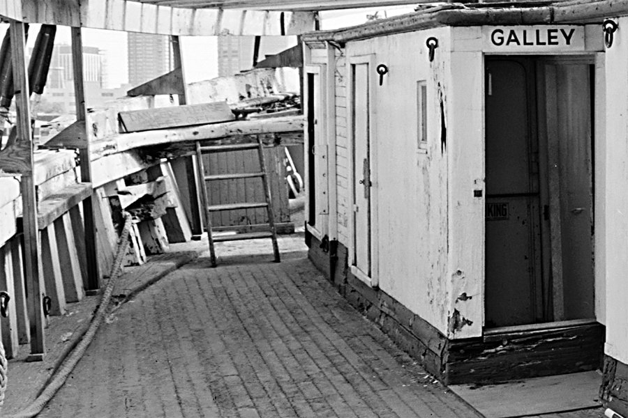
I have been trying to determine where the heads (latrines) were on small to mid sized schooners (60 to 100 foot between perpendiculars) from the late 1700s through the 1800s. I haven't found much information about them. After the bows were closed in with no beakhead I wonder where the seats of ease went? Here are a couple of photos of the Wawona from the Historic American Engineering Records (HAER). It was a three masted lumber schooner built in 1897 in San Francisco, CA, USA. The vessel had a fo'c'sle deck above the main deck at the bow. In this photo looking aft from the bow this overhead deck had rotted away, exposing the winch and the port side seat of ease to the elements. A short "bulkhead" afforded some privacy. Photos do not show the starboard area. The vessel rotted away and was scrapped. In this view looking forward (below) you can see the short bulkhead behind the ladder on the port side leading up to the fo'c'sle deck. Photos of the hull do not show any openings in the hull side in the area where the seat of ease was located. The Wawona was very similar to the C. A. Thayer that is in the nautical museum in San Francisco. But the HAER plans and photos for the Thayer do not show the seats of ease. They show one internal water closet in the aft cabin. So the Wawona photos show one possible solution. Any one have examples of other heads on smaller ships that didn't have the elaborate beakheads like the larger ships? PS: I read through the "Development of External Sanitary Facilities Aboard Ships of the Fifteenth to Nineteenth Centuries" thesis by Joe John Simmons III. It deals mainly with larger warships and has nothing about smaller vessels.
-
McMaster-Carr is a good supplier of materials, fasteners, tools, etc. We have used it in our business for decades, and I get some of my hobby materials there too: https://www.mcmaster.com/ The web site is easy to navigate, and that's good because I think they used to say they have more than a hundred thousand items!
-
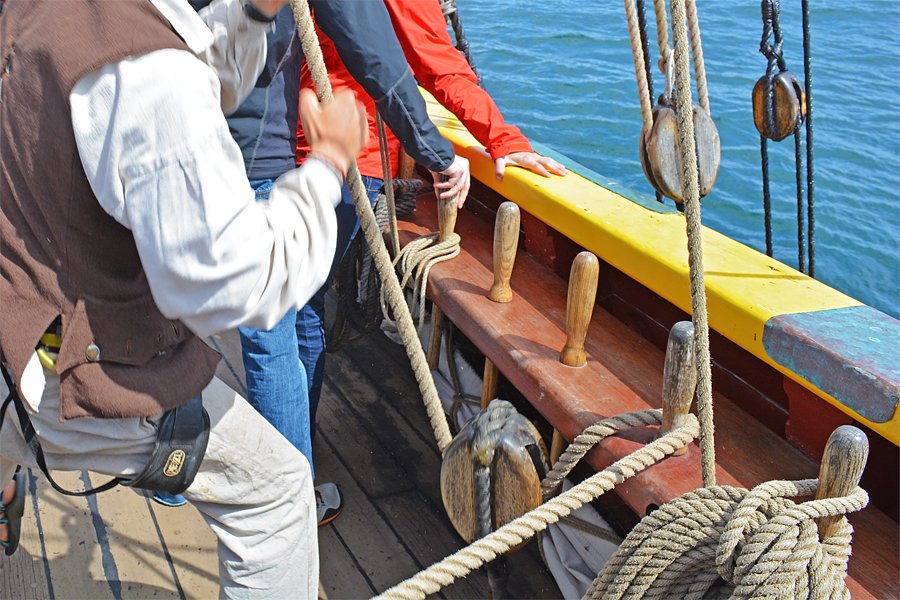
I have also been wondering about size and color of belaying pins for a 1:48 scale model. Here is a photo of pins on the Lady Washington replica ship. This is a working ship so these pins are not museum pieces. Notice how the lesser used pins are a bit shinier than the two with the ropes on them. These may just be spare pins or for occasional use, or maybe new replacement pins. I suspect these were varnished, but a couple hundred years ago the pins probably weren't varnished (too expensive). Oil from sailor's hands might well have darkened them after decades of handling, along with the common fungi that cause wood to turn gray over time. The pin at bottom right sows the "correct" way (according to some people) to attach coils of rope to a pin by pulling one of the last turns through the center of the coil and looping it over the pin - the entire coil does not hang over the pin so much of the pin is visible. Also, the crew was hauling in the line around the second pin from bottom right when the photo was taken. The line runs down through a runner block, then up and around the pin, and was being pulled to the left. The friction of lines on the pins would soon wear off any varnish, so these pins look more weathered.
-
Cleaning Brass Casting Residue
Dr PR replied to Jonathan_219's topic in Metal Work, Soldering and Metal Fittings
You mention a texture to the surfaces. I recall seeing in one of the carving threads on the forum that often the "background" surfaces between carved figures was pitted to create a surface that wasn't smooth and shiny. -
How big will the model parts be? What scale are you working in?
-
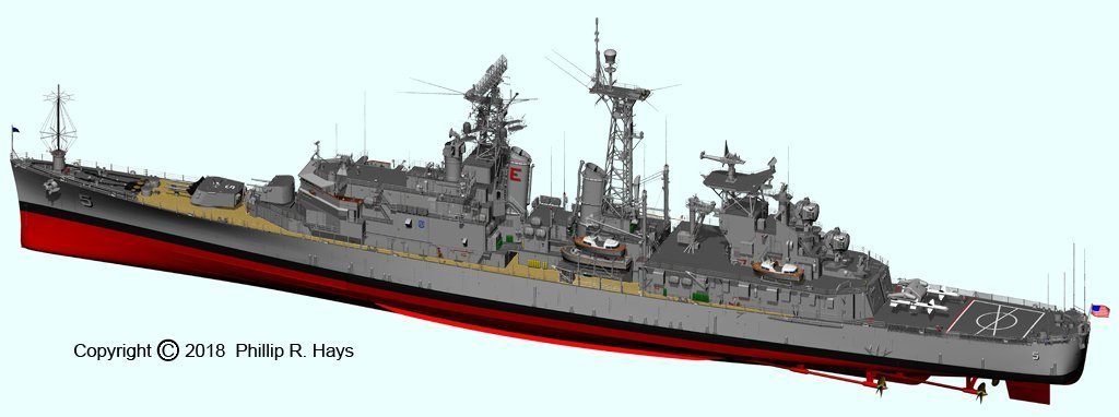
It was project 1164, a Slava class. Three were completed back in the 1980s. Moskva. Marshal Ustinov and Varyag. Ukrayina was started but not finished. Ukraine took possession after the breakup of the Soviet Union and it is in Mykolaiv, Ukraine. I think these are beautiful ships, although a bit out dated now. They served in the same flagship role as the USS Oklahoma City CG-5 that I served on. The huge anti-ship Balzat/Sandbox missiles are similar technology to the Talos missiles I worked on.

-
I have been using CAD software for 33 years, and at least 25 years working in 3D CAD, including ship modeling: https://modelshipworld.com/topic/19321-uss-oklahoma-city-clg-5-1971-3d-cad-model/?do=findComment&comment=590228 Learning to use a 3D CAD program is not an easy task for most people. It can take a year or more to become really proficient. Some programs have absolutely horrible user interfaces - what we once called "user hostile." Some of the documentation (if there is any) is abominable, and often incomprehensible. So if you are thinking of getting a CAD program be sure it has a FREE on line user forum where you can get help from other users (like this forum). Don't count on technical support from the company unless you have to pay for it, and some CAD programs charge as much as $2500 per year for technical support, and even to be able to use the user forum! This will be time spent when you are not creating your real model. But once you learn it is an extremely useful tool for figuring out how to build models, and most programs can even create files for 3D printing . **** My experience with 3D CAD newbies (I was a 3D CAD user forum monitor for decades) is that the biggest problem is that they have never "thought" in 3D. This is especially true of experienced 2D CAD users. 3D CAD is not "drawing!" Almost nothing you have learned using a 2D CAD program, Photoshop, Corel Draw and other drawing programs will help you, and will probably be an obstacle you have to get over before you can really work in 3D. In 3D CAD you are modelling in a virtual universe that you create, and you have to think in 3D. You do not create a drawing, you create an object. Some people never achieve this and their 3D CAD attempts are failures.

