
HOLIDAY DONATION DRIVE - SUPPORT MSW - DO YOUR PART TO KEEP THIS GREAT FORUM GOING! (Only 24 donations so far out of 49,000 members - C'mon guys!)
×

abelson
-
Posts
467 -
Joined
-
Last visited
Content Type
Profiles
Forums
Gallery
Events
Everything posted by abelson
-
 Excellent craftsmanship. Very clean and crisp work, and attention to detail.
 -
Well, we've come to see excellent work from you. So, it's repetitive to say excellent work. But, anyway, excellent work. I enjoy your posts. I'm not too far behind you, and I refer to your log often as I advance my build.
- 950 replies
-
- 1
-

-
- syren
- model shipways
- (and 1 more)
-
Excellent, clean, crisp, detailed work. Enjoy your photos.
- 950 replies
-
- 1
-

-
- syren
- model shipways
- (and 1 more)
-
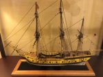
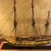
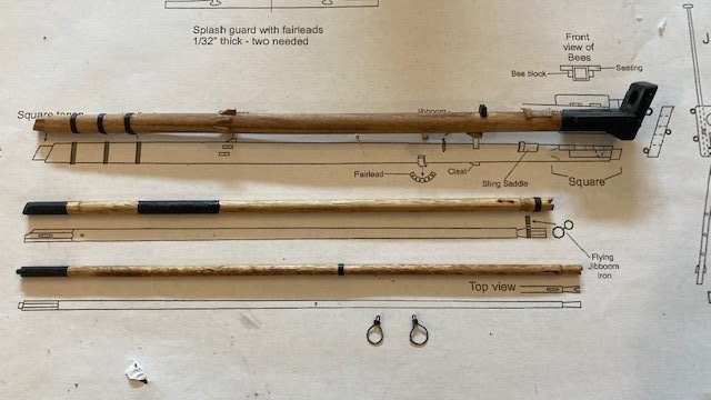
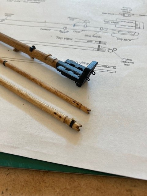
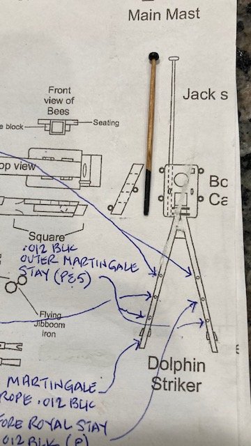
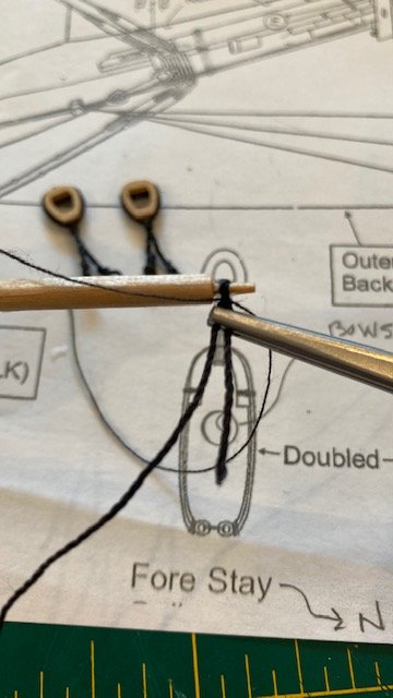
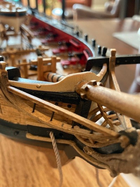
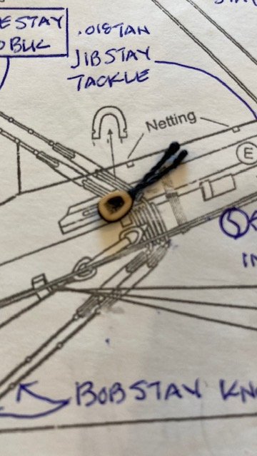
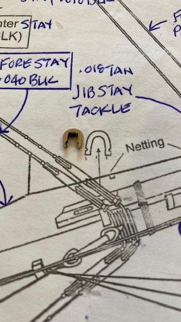
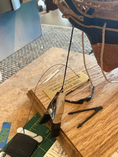
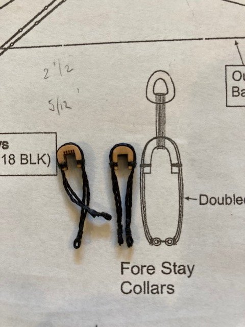
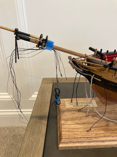
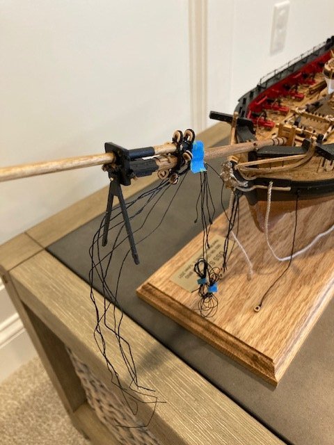
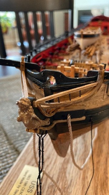
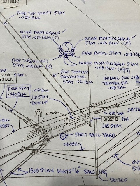
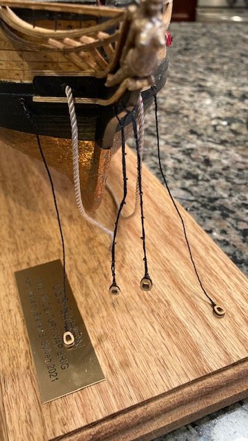
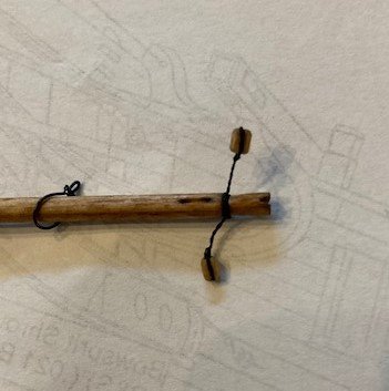
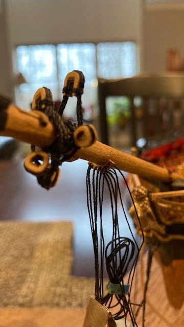
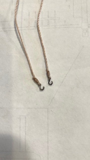
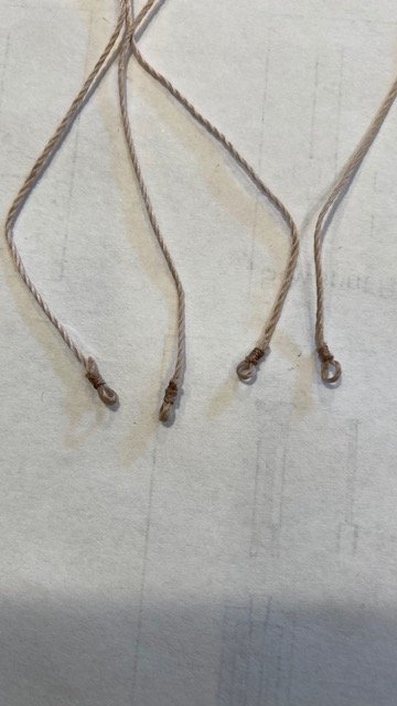
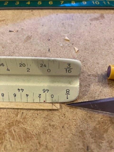
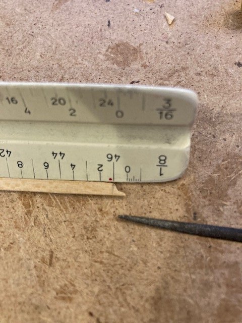
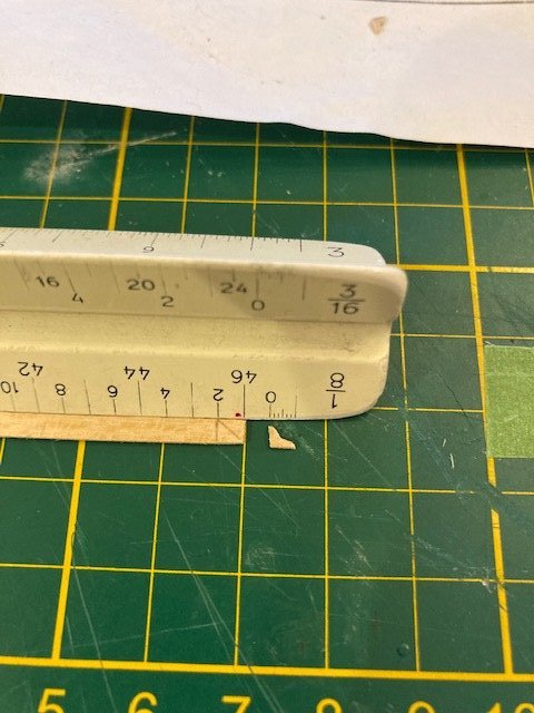
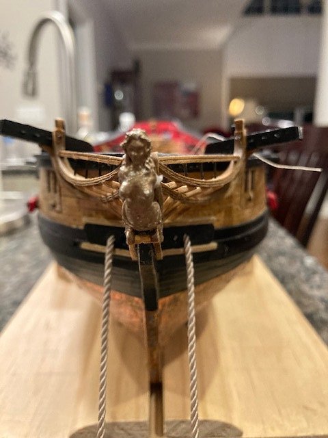
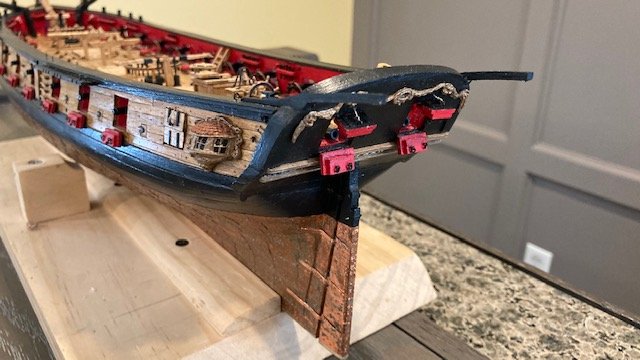
Chapter 16 – Bowsprit, Jibboom, and Flying Jibboom. The bowsprit was previously completed when I was working on Chapter 13 (see Page 2). The next step is the jibboom. The jibboom was made per the instructions using a 5/32” diameter dowel shaped as shown on the plans. This was a fairly easy task. The most difficult part is creating the octagonal shape at the inboard end of the jibboom. To simulate the iron band on the jibboom, I used a piece of 1/16” wide black pinstripe tape, secured it with CA, and painted it black. The flying jibboom was made from a 1/8” diameter dowel as per the instruction except that I didn’t taper it. This was also an easy task. The tenon on the end of the flying jibboom is rounded to fit the hole drilled in the bowsprit cap. I added the iron band to the flying jibboom a la the jibboom. I aligned the jibboom and the flying jibboom to matchup the adjacent iron bands. The jibboom and flying jibboom were painted black basically as shown in the instruction photos and stained Golden Oak. Next, I made the traveler rings for the jibboom and the flying jibboom from 28 gauge black wire. Each ring was wrapped with two turns of thin wire (gauge unknown). I applied CA to the seam where the 28 gauge wires meet. Note: Remember to slip the traveler ring onto the jibboom before the flying jibboom is glued in-place. Installing the brass photo etched piece that is used to connect the jibboom iron band to the flying jibboom iron band is bit tricky. I test fit the jibboom and flying jibboom and eyeballed the angle and locations where the photo etched piece pins will be attached. Using a needle, I punched a hole in each pinstripe band where holes will be drilled for the pins. I then drilled the holes. I inserted the photo etched connector and test fit the jibboom and flying jibboom again. I’m satisfied with the alignment. I plan to permanently assemble the jibboom and flying jibboom whence 3/32” blocks are attached to the cap and the closed heart collars are made. I made the jack staff from 1/16” dowel. I cut the dowel long enough to fit in the chuck in my Dramel. I then tapered the dowel using a sanding block and file. The ball truck was made from piece of 1/8” dowel. A divot was made in the ball truck for attaching the tip of the jack staff. The jack staff below the bowsprit cap was painted black. Above the bow sprit cap the jack staff was stained Golden Oak. The jack staff will be permanently attached later. I decided to make the dolphin striker next. This was fairly easy. It was fashioned from 1/16” x 1/16” strips. I drilled a hole at the top of the striker for inserting a pin to secure the striker to the bowsprit cap. With that done, I turned my attention to the blocks and collars. I made up six (6) 3/32” blocks with .008 black line. Lashed four blocks to the eyebolts on the bowsprit cap and two (2) on the end of the flying jib boom. At this point, I decided to check the holes in fairlead to be sure that the .012 and .018 black line stays would pass. I had to enlarge the holes. Thankfully, without damaging the fearlead - whew. I started making the bowsprit collars and almost immediately broke one of the half-open hearts. I ended up breaking all of them and had to order some from Syren. I also ordered some closed hearts. The instructions say the closed hearts are 3/16”, so I ordered 5.5mm (7/32”) closed hearts. Thinking that the half-open hearts are also 3/16”, I order 5mm half-open hearts – this was a mistake. The 5mm half-open hearts are too small (see photo). I should have scaled the half-open heart shown on Sheet 5, which is about ¼”. I had to reorder 7mm (9/32”) half-open hearts – lesson learned. In the meantime, I made the collars from .012 black line. The drawing shows a doubled line for the collars. I opted to make the closed hearts with a single line and the half-open hearts with doubled lines. Sheet 5 shows the half-open hearts straddling the jibboom but the photo on Page 79 of the instructions shows the open hearts being significantly above the jibboom. So, I guess there is a lot of leeway in the length of the collar for the forestay hearts. Most of the Syren build logs that I have perused have the half-open hearts above the jibboom to varying heights. I decided to make the open heart collars 1 7/8” long, eye to eye. To form the eyes at the end of the collar I filed down the end of a piece of dowel to a diameter that I thought was appropriate for the scale of the model. I looped the rigging line around the dowel and then seized the line with black thread (see photo). I added CA to the eye to stiffen it. I made the open heart collars 1 1/8” long. I used black thread to lash the collar at the hearts. The collars were attached to the bowsprit using black thread and a needle. The needle was passed through the eyes three times and the secured with a simple knot and some CA. The order of the collars, starting at the jibboom rest and working forward is as follows: forestay half-open heart collar, bobstay closed collar, bowsprit closed collar, bowsprit closed heart collar, forestay half-open heart collar, and bobstay closed heart collar (see sketch). While waiting for my 7mm half-open hearts order to arrive, I made the splash guard. As the instructions say, the laser cut layers are quite fragile. Two of them broke in the process of gluing them together and one split at the midpoint line. In hindsight, I marked the notch on the bottom of the layers with a pencil before gluing them together and I think this may have contributed to the layer splitting at the midpoint. I was able to glue the pieces together and salvage the splash guard. Most of the split in the top layer was removed when the bottom of the guard was notched/filed. The remaining split was filled with CA. I notched the location of the fairleads slightly and then sanded and painted the splash guard black. The fairlead notches will be completed after the splash guard is glued into position. I made some eyebolts for the Horses from 28 gauge wire and attached them to the splash guard. I made the eyebolts about 9/16” apart to match the eyebolts on the side of bowsprit cap. Still waiting for my 7mm half-open heart order, I decided to make the two bobstays. I measured the length of the bobstays on Sheet 5 from the hole in the stem to the top of the closed heart and doubled it. I allowed for the width of the stem and a little length at the bottom of the heart for seizing. I wrapped the .018 black line around the heart and applied a little CA with a toothpick to secure the line. I made the knots from .008 black line spaced 3/8” apart. I applied a little CA to the knots before trimming them. The bobstays will be lashed to their corresponding closed hearts whence the bowsprit assembly is permanently secured. Next, I made the two bowsprit shrouds from .021 black line seized to a closed heart. I seized the end of the line to a hook made from 1/32” brass eyebolts. The bowsprit shrouds will be lashed to their corresponding closed hearts whence the bowsprit assembly is permanently secured. This is the reverse order of what’s described in the instructions. One possible ramification of making up the shrouds and bobstays without first lashing them is that the spacing between the lashed hearts may not be consistent. I expect this will be the case but, hopefully, it won’t be that noticeable. My Syren order arrived, so I proceeded to make the forestay collars. I doubled up the collars. One collar has an eye at each end and the other doesn’t. I fit the collars to the half-open hearts and applied a little CA to hold the collars in-place while I seized the collars to the heart legs. I then seized the straight end collar to the eye end collar. The collars were attached to the bowsprit same as the closed heart collars. Next task, assembling the bowsprit. I had previously fit the bowsprit. It sits about 3/32” above the figurehead but I had to file the slot in the bow a little more to lower the bowsprit in order to fit the splash guard. Before gluing the bowsprit assembly together, I decided to take the advice of Jim Rogers build log and reeve the running rigging lines through the fairlead before lashing the bowsprit collars. I think this is good advice. I had a difficult enough time reeving the lines through the fearlead with the bowsprit off the ship let alone on the ship and with the collars lashed. To help me visualize the order of the lines through the fearlead, I made a sketch (see photo). I measured the length of the fore royal stay and fore top gallant stay by running the line along the corresponding line on the Sheet 5 and allowing some length to seize the respective lines around the fore royal pole and the fore top gallant mast and to set up the "bullseye" and lanyard at the bow. Time will tell whether this was actually a good idea. I set up the stiffened bullseye on the outer and inner martingale stays. I measured the length of the stays in the same manner as the fore royal and top gallant stays and made allowance for the outer and inner martingale stays to be seized to the jibboom and flying jibboom, respectively. Next up, permanently attaching the bowsprit. Stay tuned.
.jpg.23d0989e816afc45a6740df4b994953e.jpg)
.jpg.8548aafc0abc7e97b2fde4dff593faa4.jpg)
.jpg.a52de43491320e750d7a3de8f1767423.jpg)
.jpg.e5acf2ebd5a4490649faf4e81f0b7938.jpg)
.jpg.745f2d172788b59913fc8ce4e1117317.jpg)
.jpg.0b301c21c901a46d315f23e7abd84c99.jpg)
- 157 replies
-
- 6
-
-
- model shipways
- syren
- (and 1 more)
-
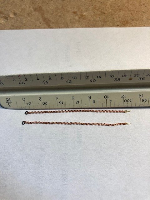
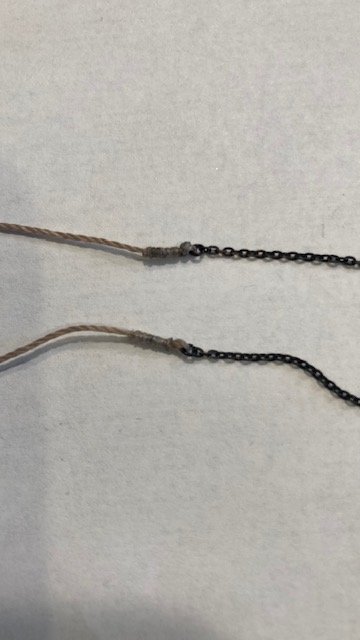
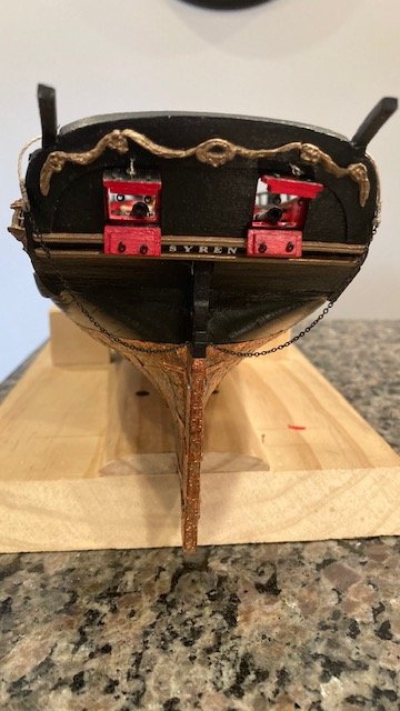
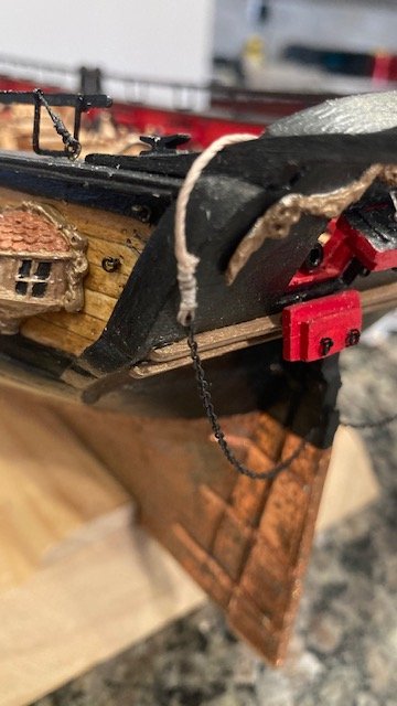
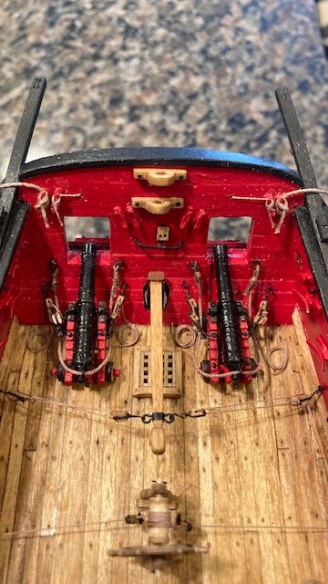
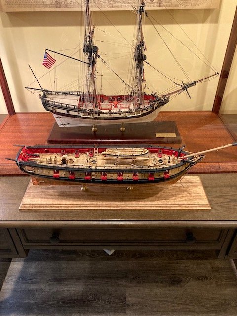
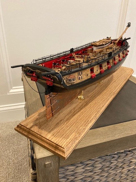
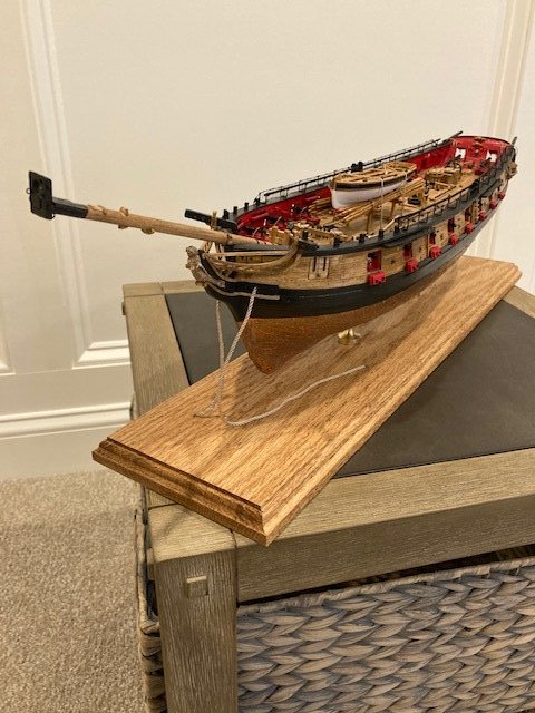
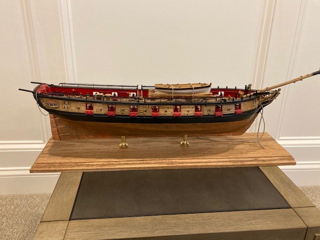
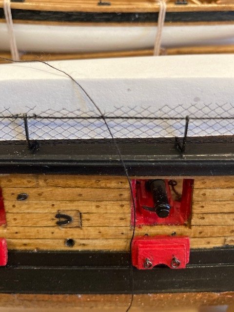
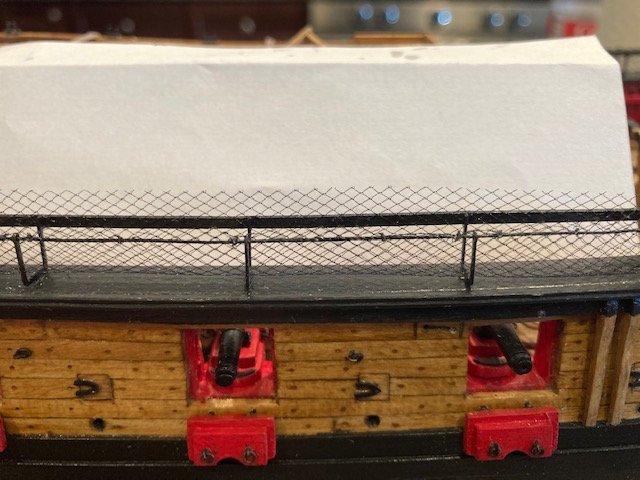
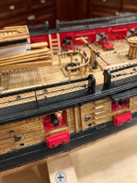
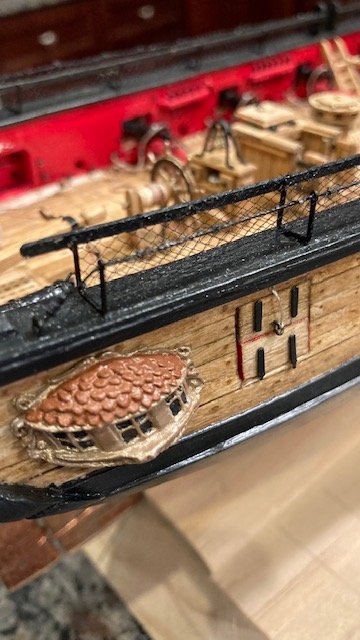
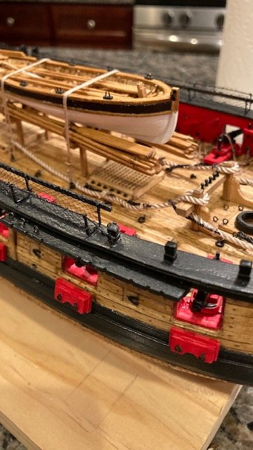
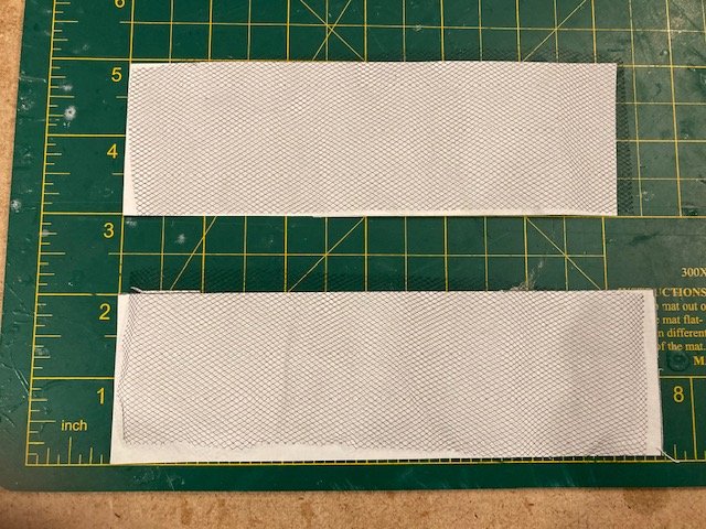
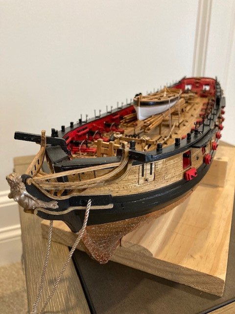
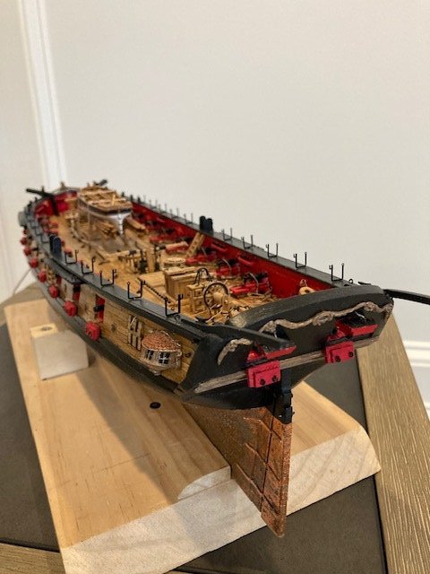
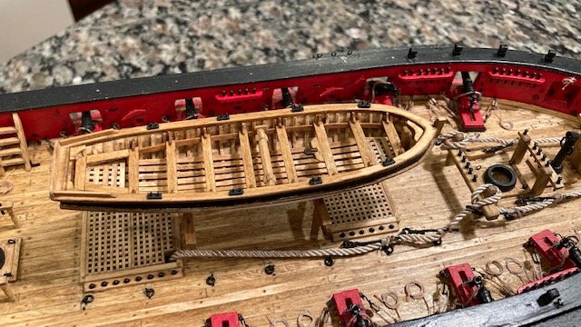
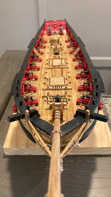
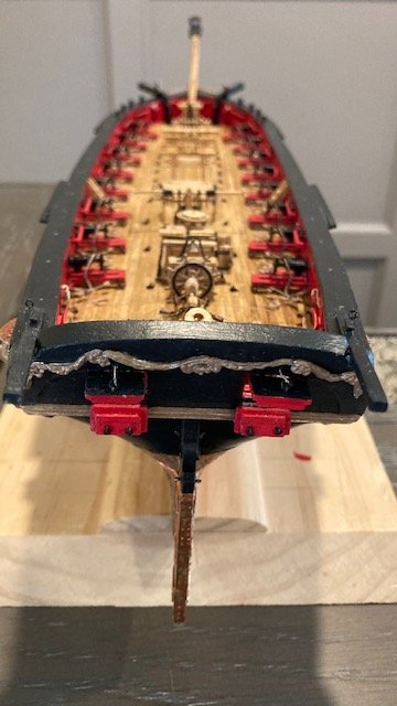
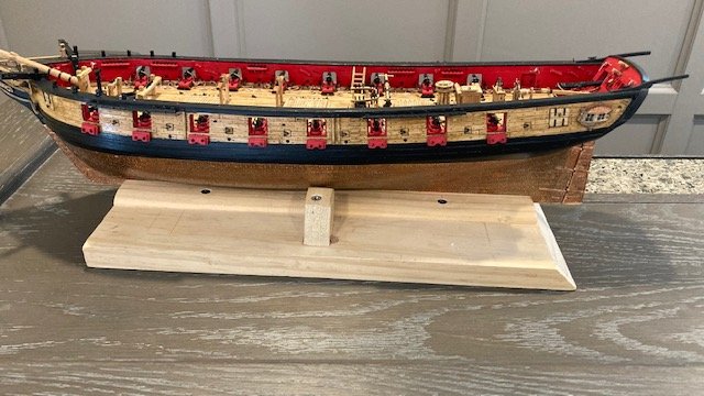
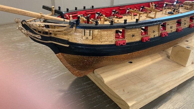
I laid the netting out and weighted it down to remove the folds. Before getting into the netting, I decided to make the rudder pendants. This was a fairly easy task. I removed one eyebolt from the rudder and attached it to the pendant chain. I inserted the eyebolt with chain into the rudder and then let the chain drape to simulate the photo in the instructions. I then cut the chain. It measures 12’ at 3/16” scale (roughly 2.5”). I then removed the eyebolt on the opposite side of the rudder, attached it to the chain and then cut the chain to the same length. I secured a ring made from 28 gauge wire to the end of each chain and then blackened the chains with Brass Black. I inserted .018 tan line through the ring the seized the line with .008 tan line. I test fit one pendent to determine what length to cut the rope. I repeated the process for the other pendent. The eyebolts were then glued to the rudder and the loose end of each rope was belayed to a cleat on the inboard side of the transom. A rope coil will be added on each cleat later. Here are some photos. Moving on to the hammock netting, I cut four (4) pieces of netting 2” wide by 6” long – so far, so good. The method I used to cut the netting was to tape down a sheet of copy paper, draw a parallel pencil line 2” above the bottom of the sheet and a perpendicular line 6” from the edge of the paper. I then placed the netting on top of the sheet with the bottom edge aligned with the bottom edge of the paper, taped the netting down, and, using a straight edge, cut the netting with an x-acto knife along the pencil lines. A clean straight line really isn’t necessary because the netting will be trimmed after it’s lashed. Lashing the netting is definitely the finicky part. I folded the netting in half in inserted it carefully into the hammock cranes. Starting at the boarding panel, I secured the netting to the inboard wood strip first. I used a piece of 1/8” x 3/16” wood strip to hold the netting down while I applied CA (with a toothpick) to the wood strip and then the outboard rigging line. This held the netting in-place. I worked my way sternward applying CA along the wood strip and at each hammock crane on the rigging line. I placed a piece of white paper behind the wood strip to make it easier to see the netting. At this point, the netting was secured. I trimmed the netting along the wood strip with tweezer grip scissors. Next, I tied-off the netting on the rigging line using a needle and black sewing thread. I made three knots between each hammock crane. I applied CA to the knots before trimming them. The netting was carefully trimmed along the top of the rigging line. The wood strip was much easier to trim than the rigging line. I did not tie the netting to the wood strip. I touched up the knots and wood strip with some black paint. The first netting install went fairly well. The next two were more of a challenge and didn’t come out as well as the first, IMO. I had to make more tie downs on the rigging line. Somehow, I misplaced one of the 2” x 6” netting pieces. I ended up using a scrape piece of netting measuring about 1” wide for the last hammock crane. I found that it was much easier to work with than the 2” wide piece. I followed the same procedure except I attached the netting at each end first. I think the last piece came out best of all. I don’t plan to make hammocks. This completes Chapter 14. Before moving on to Chapter 16, I decided to mount the ship on its display board and pedestals. The board is 1” oak (purchased at Lowes) stained with the MinWax Golden Oak and finished with a coat of polyurethane. The pedestals are from Model Expo. The base measures 22” x 5.5”. I used a router to make the decorative edge. The pedestals had to be ground down to fit the keel. I haven’t found much discussion on display boards in other build logs. I guess the size is a matter of preference. For those that may be interested, I drilled holes (back in Chapter 8 ) in the false keel, 4 1/4“ from the bow most end and 5 1/2” from the stern most end. At this point, I’m about 45 weeks into the build. Now, on to Chapter 16. I took a photo side-by-side with my Fair American for size comparison.
- 157 replies
-
- 4
-
-
- model shipways
- syren
- (and 1 more)
-
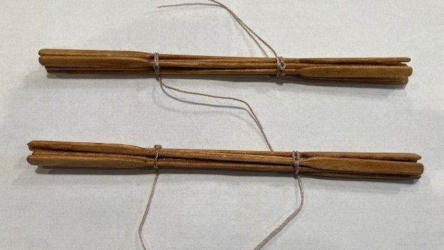
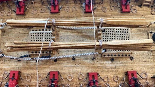
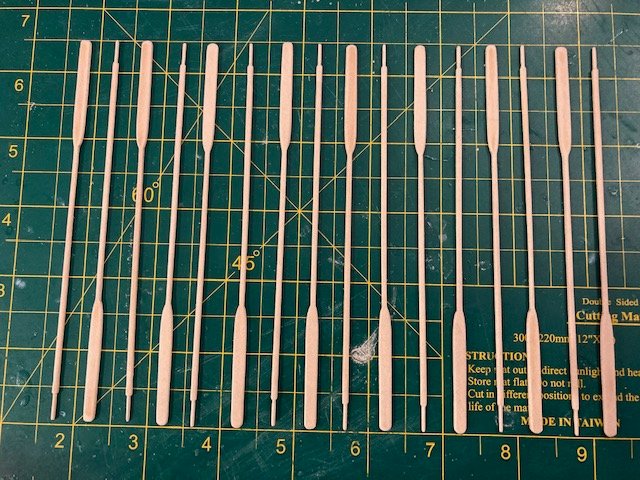
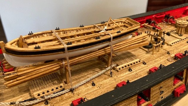
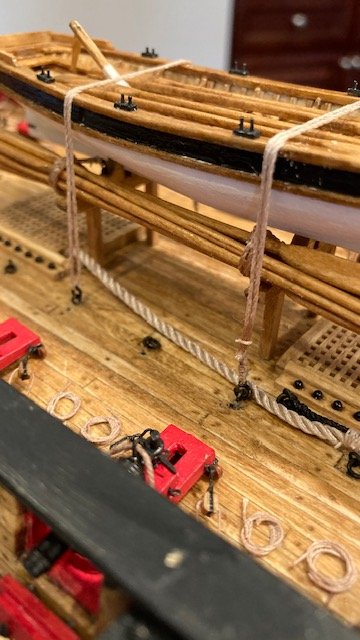
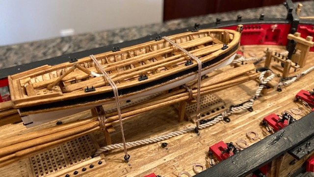
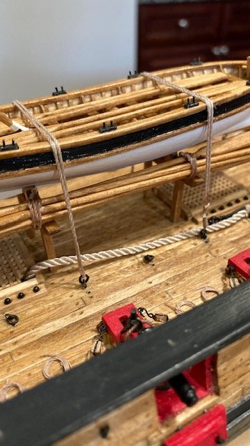
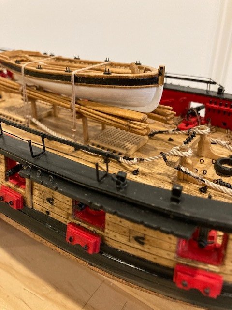
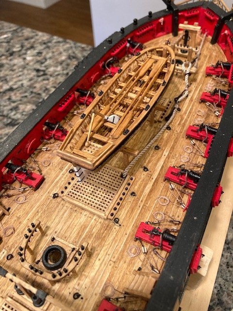
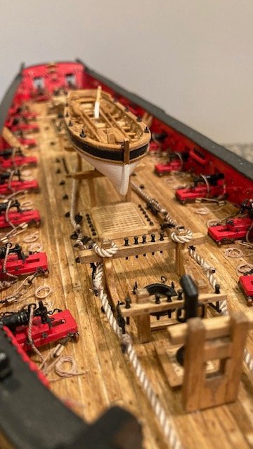
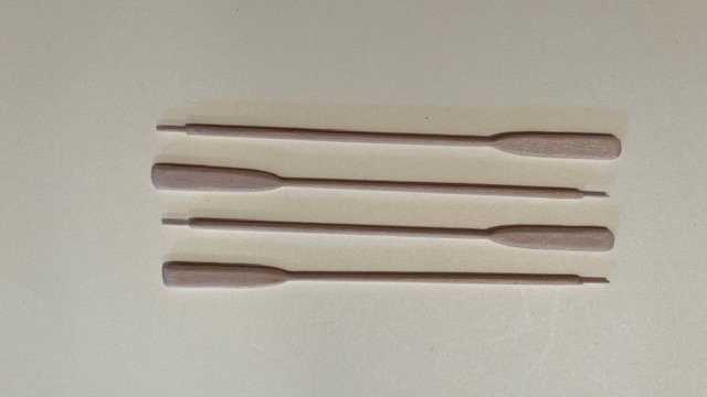
Completed the sweeps. I shaped them by hand-sanding. The amount of sanding is a matter of perfection and what meets your eye, nonetheless, a lot of sanding is necessary. I stained the sweeps Golden Oak, coated them with poly, and lashed them together in bundles of eight (8) with .018 tan rigging line. Each bundle was lashed to its respective chock – this was a little tricky. For the lashing ropes, I made an eye on one end and seized the line. I passed the loose end of the rope through the eye, wrapped it around the bundle, passed it through the eye on the chock, seized it with a simple overhand knot and cutoff the loose end. There are two (2) lashing ropes for the longboat. Each has a hook on one end. I have seen in other build logs where there is a hook on both ends of the lashing ropes. The instructions are a little fuzzy here. It says, “Create two hooks out of 28 gauge black wire. Seize them onto one end of the rigging line. Place the hook through one of the rings on deck adjacent to the gallows bitts. Take the loose end of the lashing over the longboat through the corresponding ring on the other side. Then bring it back over the top and seize the loose end to the original “pass” of the lashing with some sewing thread.” If you enlarge the photos in Chapter 15 on Page 74 it’s clear that the loose end of the lashing goes through the deck ring. I made the hooks from 1/32” brass eyebolts and blackened them with Brass Black. The hooks were seized onto one end of the rigging line with .008 tan line. I cut the lashing ropes about 12” long to allow some extra length for lashing the loose end to the original pass. According to the photo on Page 74 of the instructions, the hooks are on opposite sides of the longboat. I set mine up this way – it’s really simple. Where the loose end is seized above the hook, I used reverse tweezers to hold the line in place, applied CA to secure it, then seized the line with .008” line. Here are some photos. With the longboat done and Chapter 15 complete, I returned to Chapter 14 to complete the hammock cranes. I glued the hammock cranes and boarding panels, making sure that they are plumb. Next, I cut a 1/32” x 1/16” basswood strips to length and glued it into the slot of each hammock crane. The strips had to be thinned first to fit the slots. Rather than sand the entire strip, I made slot on the backside of the strip at each slot using a small square file. As per the instructions, one end of the strip butts up against the side of the boarding panel and the other end extends ¼” beyond the last hammock crane. I painted the strips after they were installed. In hindsight, I would have painted them before installing them because it was a little difficult painting the back side of aft most strips with the longboat lashed. Next, I ran a length of .018 black rigging line through the rings in the arms of each hammock crane. One end of the line is seized to the eye bolt on the boarding panel and the other end is seized to the eye bolt in the cap rail. To hold the tension in the line, I pulled the line through the eyebolt and applied a drop of CA on the eyebolt. Once that was done, I was able to seize the line. Next, the “finicky” task of lashing the netting to the hammock cranes. Stay tuned.
- 157 replies
-
- 2
-
-
- model shipways
- syren
- (and 1 more)
-
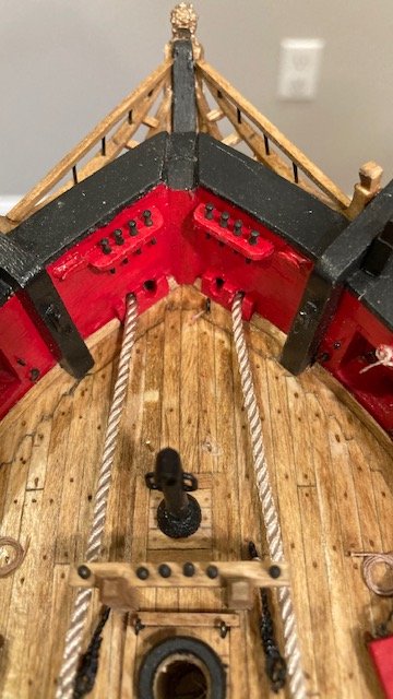
Nice rebound on fixing the hawes holes. I had a difficult time with this task too. I'm glad you checked that the 0.062” cables will pass. I didn't check mine and, consequently, had to ream the holes. In the process of doing that I damaged the hawes hole guides and had to re-do them. It's a learning process. Your ship looks great.
-
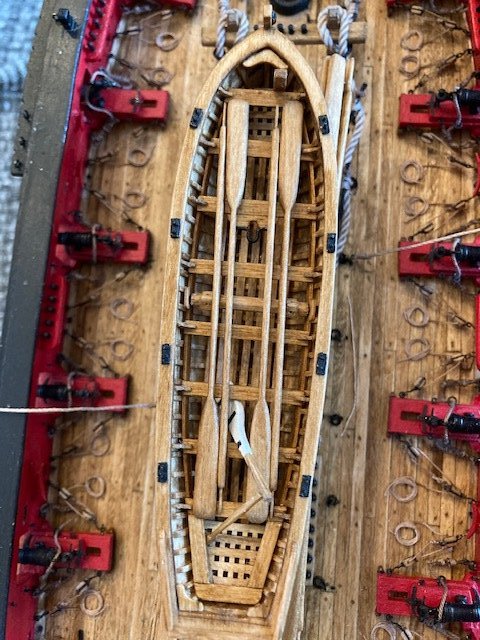
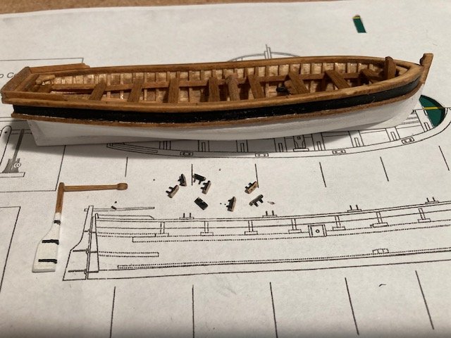
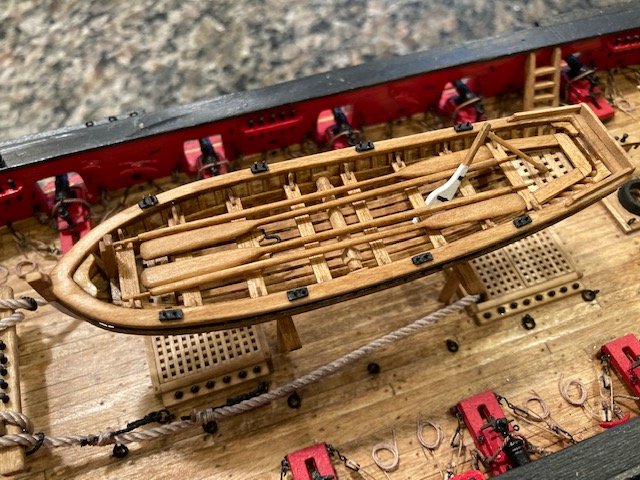
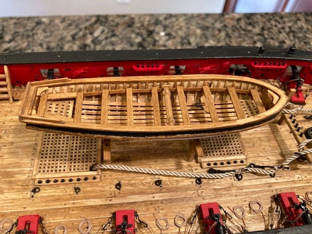
Finished the tiny knees at the ends of the thwarts; made from 1/32” x 1/16” strips. I’ve included some photos showing how I made the knees. The method I used is as follows: Mark a pencil line 1/8” from the end of the 1/32” x 1/16” strip, cut off a diagonal piece with an x-acto knife and discard, shape the end of the strip with a small half-round file and sand paper, cut off the knee from the strip, and sand/file the cut edge even. To do final shaping I held the knees with tweezers. As usual, in the process, some knees flew off the tweezer never to be found, requiring a do over. The end result was worth the effort, though. The knees were glued in-place and stained. On to the rudder. The laser cut rudder was too short, so I had to fashion one from 1/32” thick sheet of basswood. The tiller was made from 1/16” x 1/16” strip and pinned to the rudder. Pinning the rudder was difficult because the pieces are so thin. The rudder hinges were made from copper tape as per the instructions. The gudgeons for the rudder hinges were made in the same manner. I made the oarlocks from a 1/32” x 1/16” strip. Using the longboat plan as a guide, I marked the length of each oarlock by scoring the strip segmentally with an x-acto knife. Next, I marked the oarlock pins on each segment with an awl, and then drilled the holes. I applied a dab of CA between the holes to prevent the segments from splitting when they are cut from the strip. Then, I painted the strip black. The pins were made from scraps from eyebolts. I was going to use belaying pins, but the shaft diameter is too large – I was afraid of splitting the 1/32” x 1/16” strips. Lastly, I installed the small bowsprit strap (a little tricky) on the starboard side of the stem as per the instructions and stained the longboat oars and applied a finish coat of polyurethane. I wanted the see if the longboat floats and it does (see photo) – silly me. Next up, the sweeps. Following are photos of the finished longboat.
.jpg.d46f6b3a6d928c795eb61d2622c09ac1.jpg)
.jpg.389994c6ab2c819758d4ada9bf12c662.jpg)
.jpg.f747cedb8964074efe98b52c170e6031.jpg)
.jpg.80b66471b3cfecc9659e255890bdfd96.jpg)
.jpg.d3ee6ae4b33f411bbf33f8b94f4fb69f.jpg)
.jpg.c9a176b30da798019d0c2fdd4c1b17c3.jpg)
.jpg.9939c3d5ca4feece4e5a7c60bf318dd1.jpg)
.jpg.12350813c23a63e182859c769351d726.jpg)
.jpg.e94893106632e1f495bcdf61fccc194d.jpg)
.jpg.1007d318f4c25370080b2777cd4efdd5.jpg)
- 157 replies
-
- 3
-
-
- model shipways
- syren
- (and 1 more)
-
Thanks for the kind words.
-
Thanks, Patrick. Your words are encouraging. It's not perfect, but we don't live in a perfect world. I'm satisfied with how it came out, although I still have a little work to do -primarily the knees (UGH!).
- 157 replies
-
- 1
-
-
- model shipways
- syren
- (and 1 more)
-
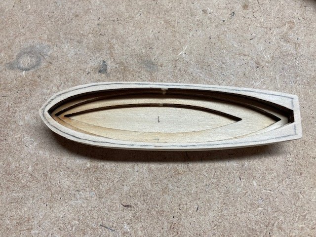
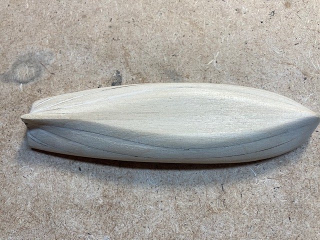
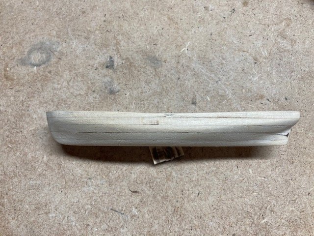
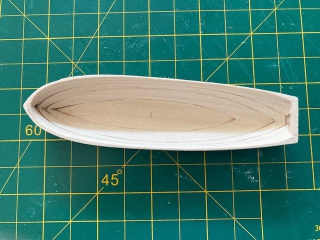
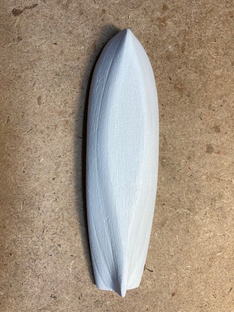
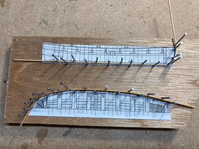
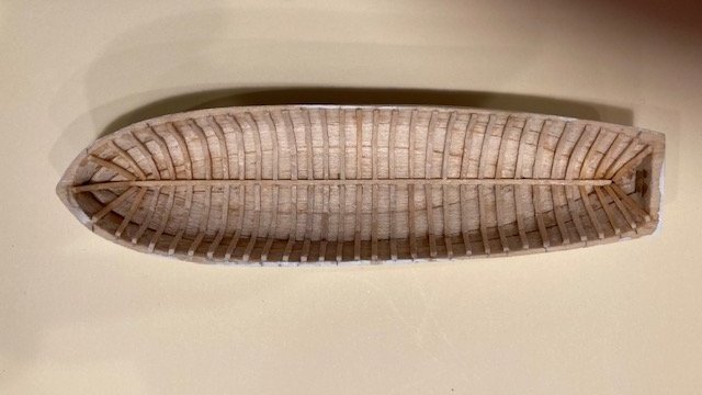
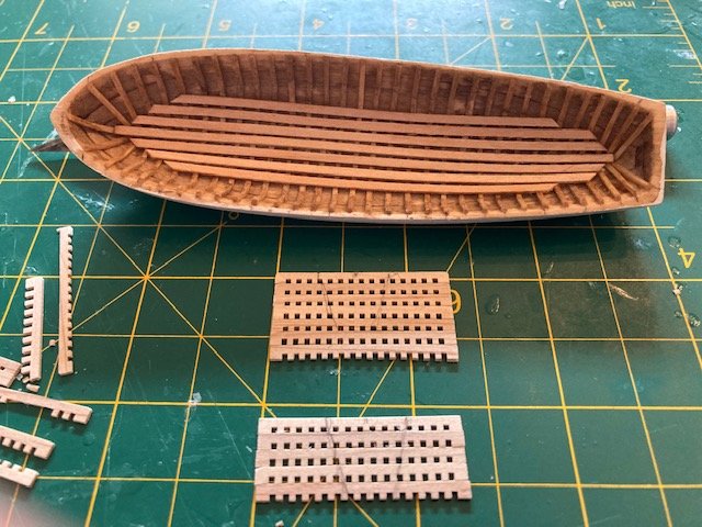
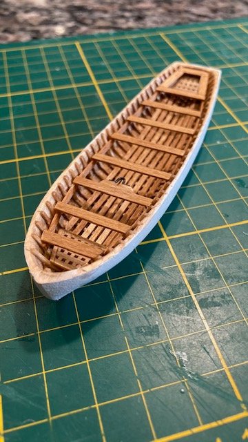
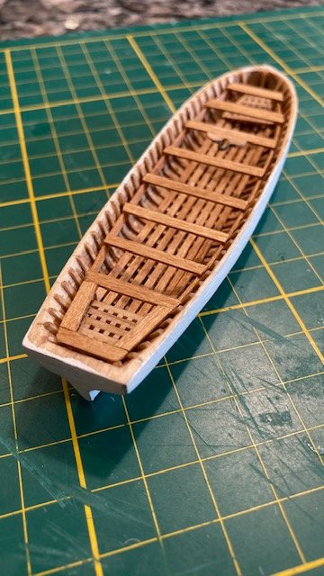
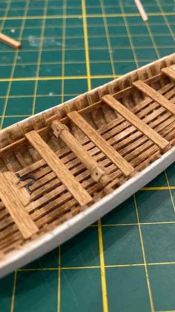
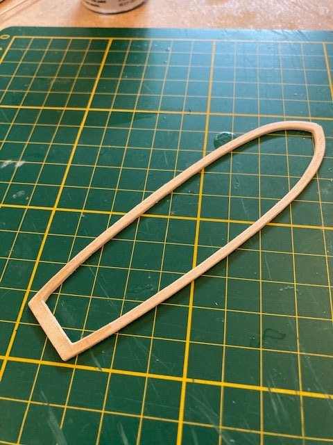
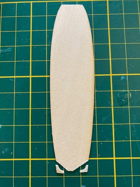
Chapter 15 - The Long Boat: Began the longboat by removing the five laser cut lifts and then gluing them together with white carpenter’s glue. I added some CA along the exterior joints to secure the lifts more quickly - I didn’t want to wait long for the white glue to dry before sanding. I left the tabs on to make it easier to hold the lifts while sanding. I used a sanding drum attached to my Dremel and coarse to fine sandpaper. After sanding to the desired shape, I filled in the joints with wood filler and sanded the hull. At this point, I cut the tabs off on a slight angle as shown in the instruction manual. To establish the shear profile, using the plan on Sheet 4, I drew a parallel line between the bow and the stern and scaled the distance (6” +/- at 3/16” scale) between the parallel line and the bottom of the rail. I drew a line on the hull to mark the shear and then carefully sanded the upper lift to the shear line using a drum sander attachment on my Dremel. Next, I shaped the interior of the hull by cutting out some of the excess lifts with an x-acto knife, and then the arduous task of sanding the hull to the desired shape. I used the Dremel and hand sanding with a combination of coarse to fine sandpaper. At the bow and stern, I used files to further define the shape. I primed the exterior of the hull and applied two coats of white (MS4831) paint – sanding between coats. A third coat will be applied after the keel and stem are installed. Next, I cut out the longboat plan and elevation views from Sheet 4 and used them to make a jig for bending the center strip and the molding strip below the cap rail. I glued the center strip in-place with CA. Neither the plans nor instruction manual indicated the number of 1/32” x 1/32” hull frames, only that they should be 3/32” apart. From photos in Chapter 15 and other build logs, I determined that there are between 29 and 31 frames from bow to stern depending on spacing. I ended up with 31 frames. I tried bending the pre-soaked the 1/32”x 1/32” boxwood strips in a jig made from a plan of the cross-section of the hull, but the strips kinked. So, I decided to just soak them and bend them by hand. This worked out fairly well, although some of the strips still kinked when installed. However, most of the kinks will be covered by the bottom battens (floorboards). I spaced the frames at about 8” apart at a 3/16” scale which is equivalent to about 4.5/32. I applied Minwax Pre-Stain to the hull followed by one coat of Minwax Golden Oak. The result is a little blotchy but it may not be that noticeable once the thwarts and grates are in-place. Next the floorboards and grates. The seven floorboards (1/32” x 1/16” basswood strips) were shaped and glued onto the frames with CA. I used a 1/32” x 1/16” strip as a spacer. The floorboards were stained Golden Oak after they were in-place. The 1/32” x 1/16” thwart support was installed next. It was stained prior to gluing it to the frames. The grates were trimmed. laid flat, and glued together top edge to bottom edge. The thwart supports and thwarts were made next, pre-stained, and glued in-place with CA. The thwart supports were made from 1/32” x 1/16” basswood strip. The thwarts were made from 1/8” x 1/32” strips. The thwart with the 22 gauge iron strap to support the mast was cut out of the 1/32” x 1/16” strip and glued to the thwart. The windlass was made from 3/32” x 3/32” stock per the instructions – a lot of filing to get it to its octagonal shape. The windlass was secured to the thwart supports with pieces of 1/32” x 1/16” strips cut to a length of about 5/32”. These pieces are very small, and they were difficult to handle while shaping and filing the small notch on the bottom edge that fits over the 28 gauge wire in the end of the windlass. And, of cause, one of the pieces flew off the tweezers never to be found. The instructions say to cut the cap rail from a 1/32" thick sheet of basswood, but the kit comes with a laser cut cap rail. The laser cut cap rail didn’t fit well, so I ended up making one from a sheet of 1/32” basswood (cut with a jeweler saw) as per the instructions, making sure to have a little overhang inboard and outboard. Before gluing the cap rail, I gave the hull a third coat of paint, marked the area between the cap rail and the molding with a pencil, applied masking tape along the pencil line, and painted the area black. I didn’t like the fit of the laser cut the keel and stem so I made them in separate pieces from a 1/32” thick sheet of basswood, sanded them, and glued them to the hull with CA. A little bit of wood filler was applied and sanded to fill in gaps. The keel and stem were painted white. Note that the keel and stem above the molding strip is not painted. I forgot to take pictures of the keel and stem. Before gluing the cap rail on I did most of the sanding. The cap rail is tricky to install because of the sheer profile. I used CA. I glued the bow and the stern and then the mid ship. I applied the CA to the underside of the cap rail with a toothpick. I find that the CA flows nicely within the space between the cap rail and the hull. The 1/32” x 1/32” molding strips were pre-stained and glued to the hull below the cap rail. The strips were soaked and pre-bent in the jig. In the process of gluing the starboard side molding, the molding snapped. So, I had to repeat the process. I used CA to attach the moldings. I tack glued the molding to the keel first and then applied CA to the underside of the molding. I used a piece of 1/8” x 1/16” strip as a guide to maintain the parallel between the rail cap and the molding. Next came the knees. I found the knees to be the most difficult part of the longboat build, basically because they’re so small. I made the bow and stern knees from the cutout part of the laser cut top rail. I traced the knees from the plan view on Sheet 4, cut them out, and used them as templates. I transferred the shape of the knees onto the bow and stern ends of the laser cut piece, and carefully cut them out. The knee pieces were filed and sanded. In the sanding process, I broke two of the knees. Rather then a do over, I glued the pieces together with white glue and then applied CA to the back side of the knee to strengthen it – this works well. Before making the tiny knees at the ends of the thwarts, I made the bowsprit step and the splash guards. The bowsprit step was made from 3/32” x 3/32” strip of basswood, notched, and glued into position as per the instructions. I made the splash guards at the stern per the instructions, except for the end panel. The end panel is slightly higher than the side panels. I cut down a piece of 1/8” x 1/32” basswood strip for the end panel and used a 1/32” x 1/16” strip for the side panels. The splashed guards were glued to the rail cap and stained after. I plan to make the tiny knees at the ends of the thwarts later along with the oarlocks and the rudder. For now, I decided to sand the four laser cut oars. They're delicate, so I was fearful of breaking them. Alas, no breakage. The shape of them is more or less whatever meets your eye.
.jpg.9e908d2bb7a13fab0f31bc1ba81ca881.jpg)
.jpg.45ee55909178bc99b53cacf11e15ebd1.jpg)
.jpg.aa7e4daa15ee4317eb2c729ff1d14bc8.jpg)
.jpg.69073ba7f5297f5d1a48d9f8f508f3c1.jpg)
.jpg.01e5db5892e41fc5236fc055acd3c803.jpg)
.jpg.c4291d83a31d4b5ef0ce37187dd7906c.jpg)
.jpg.fd6091a87009d306c91ca620706acec3.jpg)
.jpg.b9ab9300f6b7fbb831a86e7b99a57c90.jpg)
.jpg.d6c714ef874ca99246c1dcf3b34216dd.jpg)
.jpg.4c0b7b8938f343352c09639c0d07d84d.jpg)
- 157 replies
-
- 6
-
-
- model shipways
- syren
- (and 1 more)
-
I've yet to experience a model ship build that didn't have a certain level of frustration. Yes, it's good to take a break and regroup.
-
My approach was to cut the joggle in a plank, trace the shape onto the margin plank, notch out the shape with an x-acto knife, and file the notch to get a relatively clean edge. I used the first joggled plank as a template for planks 6, 7 and 8. Thereafter, the diagonal part of each joggle gets longer as you work aft along the margin plank, so each joggle will be different. I rather enjoyed this part of the build. I think once you get into it you'll enjoy it too.
-
I had a similar problem. For me, the simplest solution was to fill it and paint it black. Then it's out of sight, out of mind. I have not regretted it. Black paint covers a multitude of sins. On the other hand, it does covers a lot of detail.
-
Your jolly boat looks great. Yes, it's a little off center but on the original ship it probably wasn't exactly centered either. It gives your ship character.
- 950 replies
-
- 2
-
-
- syren
- model shipways
- (and 1 more)
-
Looking good!
-
Excellent work on the jolly boat. A task well done. A nice addition to your build. You'll look back at it and say wow, I did that?
- 950 replies
-
- 3
-
-
- syren
- model shipways
- (and 1 more)
-
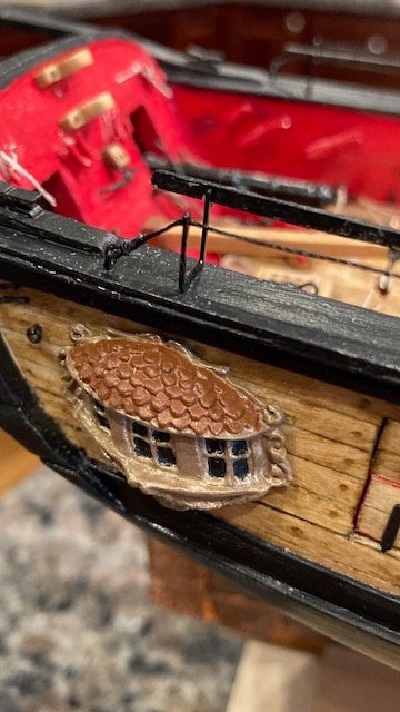
I like the carvings and admire your initiative to create them. IMP, they're a bit large. But, you've already gone beyond the realm of authenticity and it's your design, so it makes no matter. Whatever floats your boat.
-
Thanks. It's funny how things somehow seem to work out in the end.
-
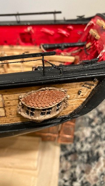
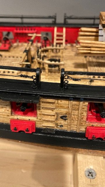
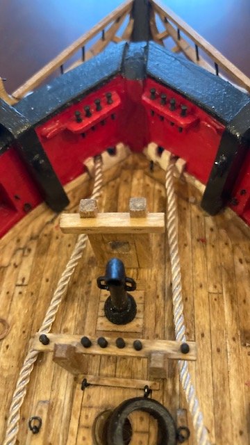
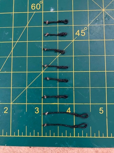
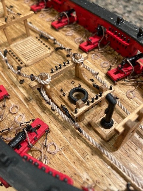
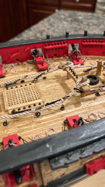
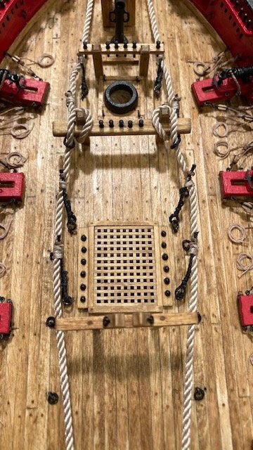
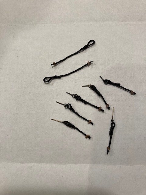
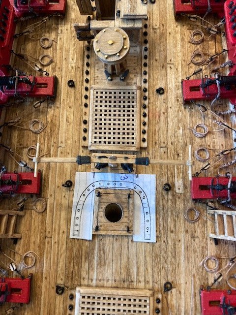
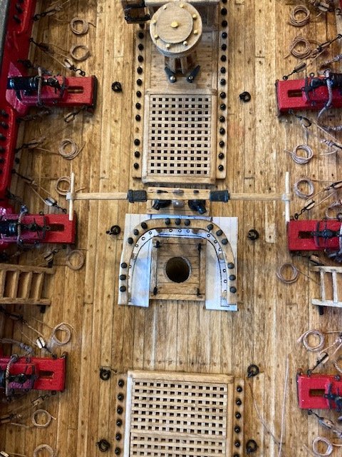
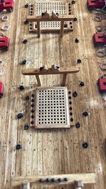
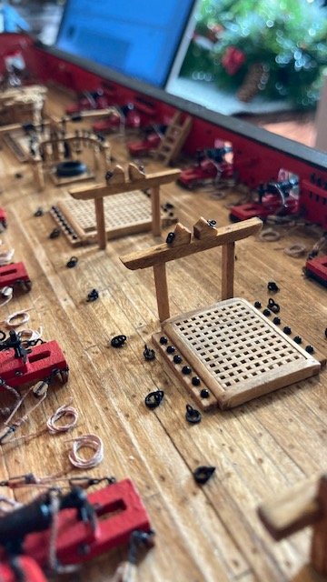
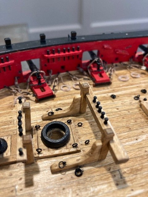
Before embarking on making the longboat, I decided to run the anchor cable and make and install the stoppers ahead of time before all the hammock cranes and rigging are in the way. I had seen the stoppers on some other build logs, i.e., Dubz, Gahm, and JesseLee, and liked the added detail of them. I understand stoppers were used to prevent an anchor from running away if it somehow breaks loose. They are attached to iron rings on the deck (installed in my last post) then secured to the anchor cable. There is no discussion on anchor stoppers in the instruction manual. I have some photos from Dubz’ build log but no description of exactly how the stoppers were made So, I decided to make them from .028” black line. I looped the stopper line around a toothpick and held it in-place with tweezers. I applied CA to stiffen the loop and then seized the line with a few wraps of .008” black line. I cut the line about ¾” long (judging from Dubz’ photos). I made six (6) stoppers. I applied CA to stiffen the line. There are also two other stoppers in Dubz photo that are not attached to iron rings. These have larger loops and appear to be longer. I made them from .028” black line and cut them 1.5” long. Note: I ended up cutting these shorter (1”). The stoppers have a knot at the end, which I made from .018” tan line. The cable is .070” manila hemp supplied with the kit. I wanted to run the cable completely though the hawes hole. I discovered the diameter of the hawes hole that I had previously drilled wouldn’t accommodate the .070” cable (shame on me). So, I had to ream it. In so doing, I damaged the hawes hole guides, and had to replace them. I also damaged the layer of wood for the hawse holes on the port side and had to repair that too. I The guides were made from 1/16” basswood sheet. I didn’t give much attention to these the first go around, so I thought I would add some photos this time. In hindsight, I should have left well enough alone. The moral of the story is, drill the hawes hole large enough to accommodate the cable. Anyway, I’m pleased with the new version of the guides. I laid out the cables on the deck. Note: It's important to drill the holes for inserting the cable in the grating deep enough to accommodate enough cable to adjust the cable length as necessary. I attached the stoppers to the iron rings. I attached the stoppers to the cable by tying a length of .008” to each stopper at the knot and applying a dab of CA. I cut off one end the line at the stopper and cut off the other end of the line long enough to be wrapped around the cable and stopper 4 or 5 times. I used a sewing needle to aid in seizing the line. The end of the line was threaded through the cable and cut off. I’m glad I added the stoppers. Now, its on to the longboat.

- 157 replies
-
- 4
-
-
- model shipways
- syren
- (and 1 more)
-
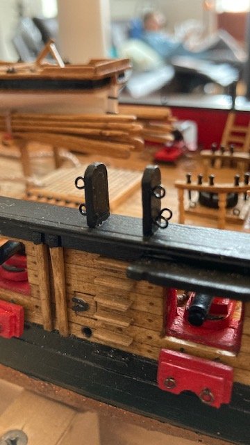
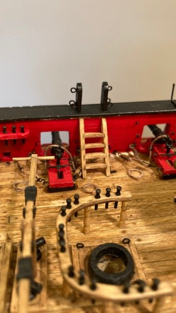
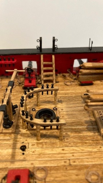
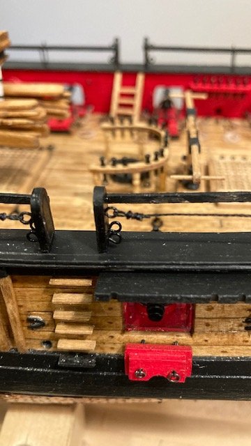
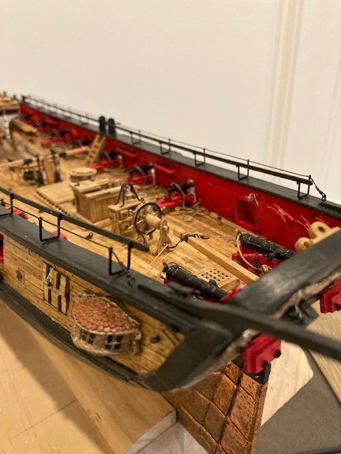
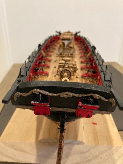
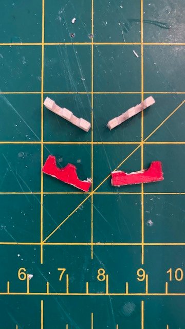
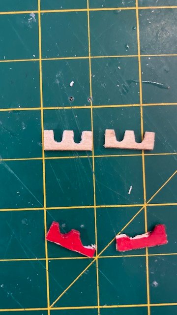
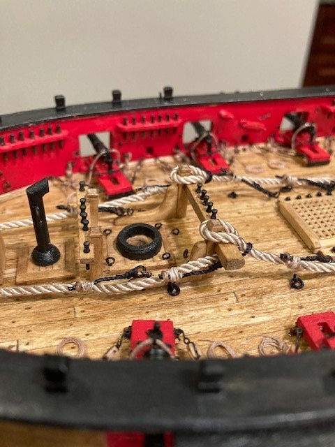
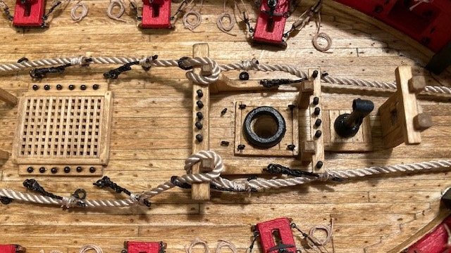
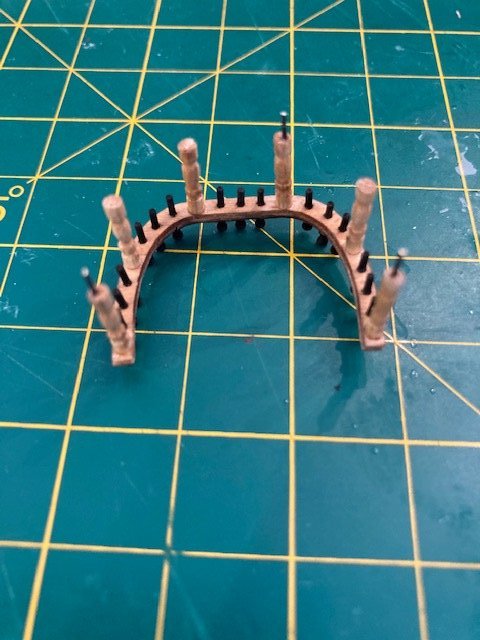
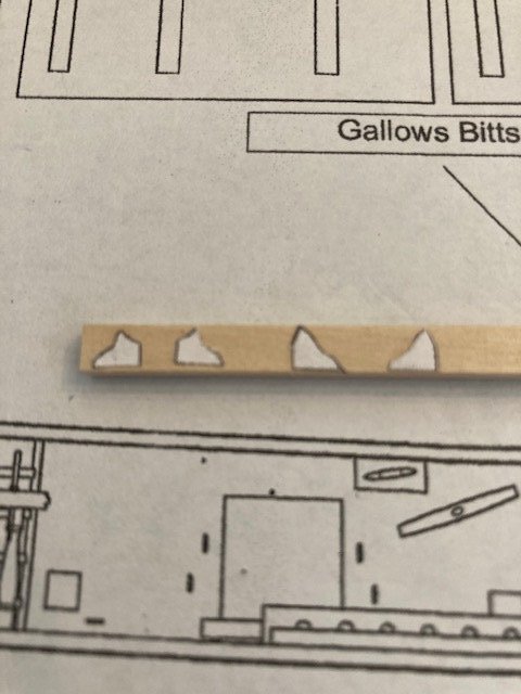
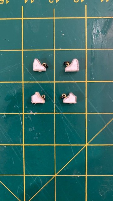
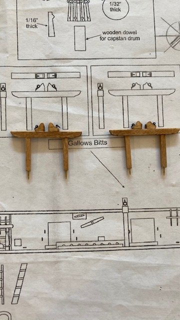
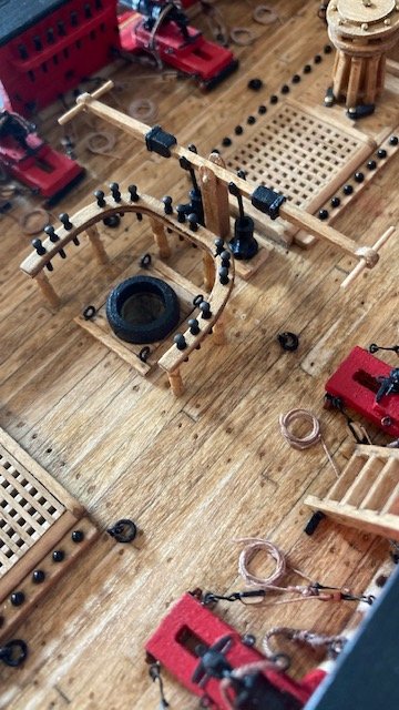
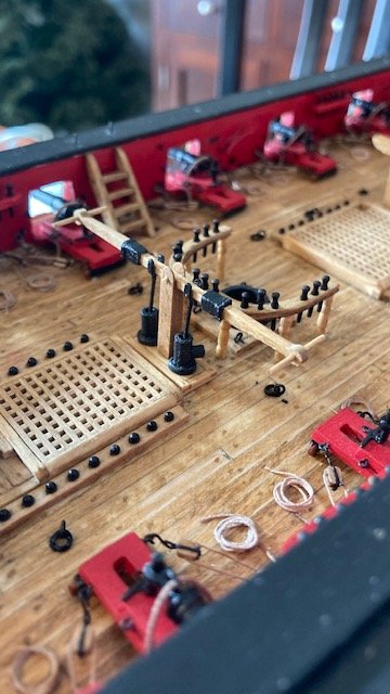
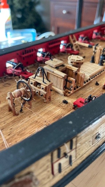
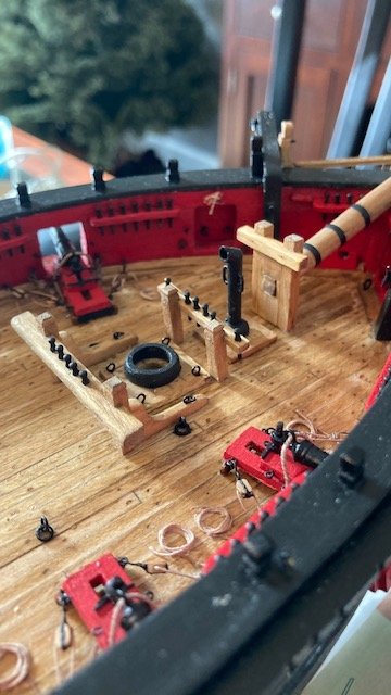
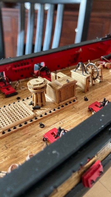
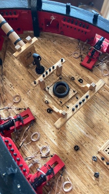
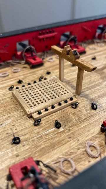
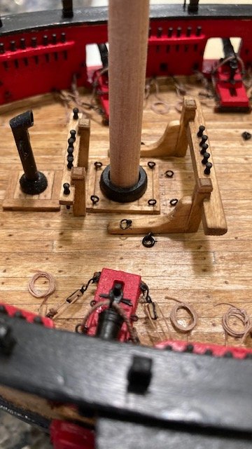
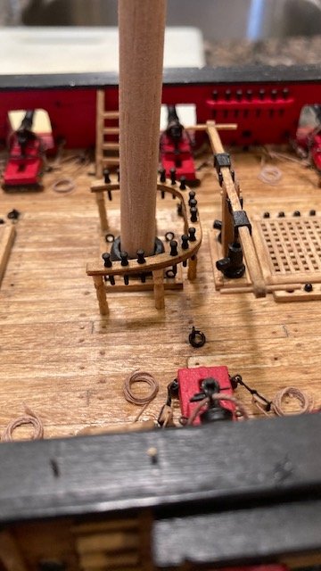
Happy New Year! Frist post of 2021. Completed the rope coils – not one of my favorite tasks or best effort, for that matter. As I described in a prior post, the coils were made by wrapping .008” tan rope around a 3/16” dowel (see photo) 4 or 5 times and applying some watered down carpenters glue to it. When dry, the coil is slid off the dowel, flattened, and the loose ends trimmed. The coils were glued to the deck with dab of white glue. Moved on to permanently installing the deck fittings. I decided to pin the fife rail to the deck. I was hesitant to do this for fear of breaking the stanchions. I only did 3 pins – I didn’t want to press my luck. Alas, I was able to drill the stanchions and insert the pins. For drilling the holes in the deck for the pins, I cut out the plan view of the fife rail from Sheet 1 and transferred it to the deck. I positioned the fife rail on the plan, marked the pin locations, and drilled the holes. Next, I made the gallows bitts chocks, even though they will be mostly hidden. I haven’t seen much attention, if any, to these on other build logs. The aft-most gallows bitts chocks are different than the stern-most gallows bitts chocks. I cut out the chocks from the Plan Sheet 4 and glued them to a 1/8” x 1/8” boxwood strip. I then shape each chock by cutting, filing, and sanding to the profile line, and then removed the paper template. The chocks were stained Golden Oak and glued to the gallows bitts. I added an eyebolt and split ring to each chock. The split rings will be used to lash the sweeps to the gallows bitts. A la Gahm’s, Dubz’, and JesseLee’s build logs, I added 2 eye bolts with split ring for the anchor cable stoppers on each side of the aft-most hatch and on each knee of the riding bitts. With that done, I decided to hold off on finishing the hammock cranes until I finish the long boat. This will afford more room to install and lash the long boat. I’ve added a bunch of photos. Next up, the longboat.
.jpg.4e50b4f256c2c870afba7a8a814e77b7.jpg)
.jpg.77d23d0fc06f7923e093d4dd42bcdd99.jpg)
- 157 replies
-
- 5
-
-
- model shipways
- syren
- (and 1 more)