


iMustBeCrazy
-
Posts
975 -
Joined
-
Last visited
Content Type
Profiles
Forums
Gallery
Events
Posts posted by iMustBeCrazy
-
-
-
-
-
-
I think the last block is just hidden in the shadows.
- mtaylor and thibaultron
-
 2
2
-
Flotherwoode seems to be fake wood grain.
Queen Elizabeth employed Leonard Fryer to decorate the long gallery at Oatlands with a woodgrain pattern in 1598. He primed the panelling with white lead paint and then painted imitation "flotherwoode", with gold and silver highlights on the mouldings, with arabesque patterns and paintwork of "markatree", perhaps resembling marquetry.
So, ornate paintwork seems to be the theme.
-
29 minutes ago, bruce d said:
If so, who is the legitimate source please?
Seems to be "Royal Navy Captain, 1805" by Alexandros Models (
whoever they arehttp://www.alexandrosmodels.com/). -
Again, I think there were more exceptions than rules:
https://www.rmg.co.uk/collections/objects/rmgc-object-535332
- mtaylor and GrandpaPhil
-
2
-
11 hours ago, Gregory said:
Here is a drawing from Lavery's 'Arming & Fitting -etc.. '
Which is a copy of HIL210 from the RMG.
This is a drawing by a shipbuilder not the Admiralty which might explain some differences.
-
-
3 hours ago, Boerscht said:
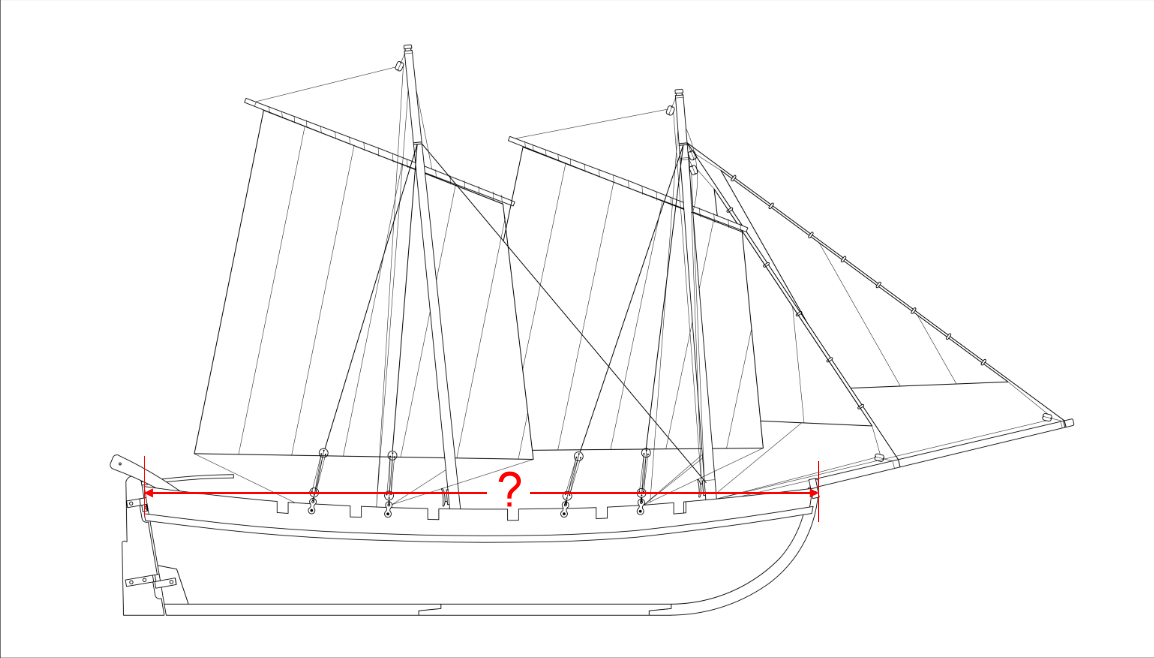
the Occre Bounty boat 1:24
I have been trying to work out what size boat this model depicts, could you do one measurement for me?
Thanks,
-
-
7 hours ago, bruce d said:
I'm wondering if the mystery items are for a specific task.
I would think so, but I also think it's a boat built for a specific task rather than modifications. It's too nice a drawing.
The bow roller looks like a normal anchor handling roller, the stern roller 'feels' like it serves the same purpose but the drawing provides no details.
It's
possiblenot impossible that these could be used together to carry a cannon slung under the hull. Combine that with four swivel guns and we may have something fit to support a landing somewhere. Not impossible but...........fantasy perhaps?4 hours ago, Roger Pellett said:C is definitely the horse for of the fore sail sheet. The circular arc allows the sail to cross over without releasing the sheet when the boat is tacked; a self tacking sail.
Yes, but it's backwards.
4 hours ago, Roger Pellett said:A wild *** guess. I wonder if it is a pump.
I don't think so but it's a better guess than any I can propose at this time.
-
-
20 minutes ago, vaddoc said:
If you guys could turn a blind eye, we could go for 40 cm that is technically much more feasible and still give the visual impression of a log oar.
Well, they might reach the water when fully loaded
") Hmm, I thought I did a similar cheat on my 16ft cutter but now I'm not sure. I think I dislike oars.
Hmm, I thought I did a similar cheat on my 16ft cutter but now I'm not sure. I think I dislike oars.
-
-
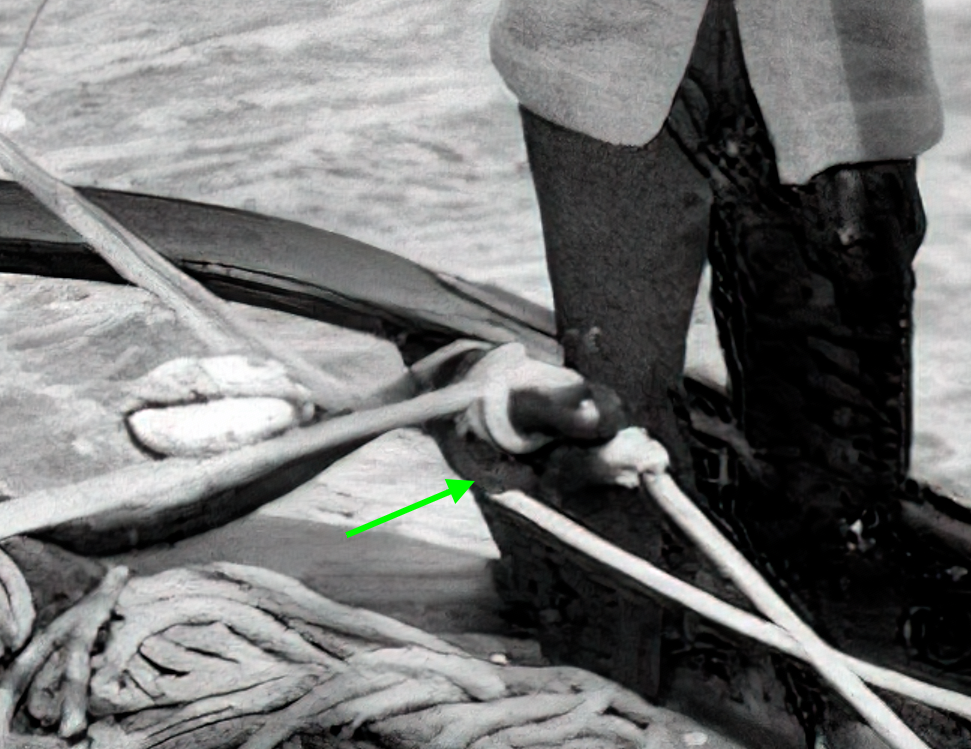
G'day Allan. This drawing contains a few enigmas doesn't it?
'A' and it's mate/s in the bow look like sockets to me, the top section being drawn in black ink suggests they are near or on the gunwale, either for an awning stanchion or a small swivel gun. THIS would fit nicely.
'B' No idea at the moment but the red ink suggests it's near the centre line.
'C' (just in front of the mast) You didn't ask but it's probably a 'horse' for the jib sheet, Maybe?
It would have been nice if the showed A, B and C on both drawings.
Other interesting things: Double lifting eyes fore and aft, rollers fore and aft, cant frames fore and aft.
-
-
Looks great! I really like the colour choices.
1 hour ago, vaddoc said:but surface underneath far from perfect
I think you and I suffer from the same issue, the desire to make a wooden hull hewn with hand tools look like fibreglass popped from a mould.
1 hour ago, vaddoc said:Still have to make oars though
At least it's single banked, only six to make.
-
And so we come to a rather delicate subject, one not much talked about in polite society since the advent of indoor plumbing. The backside!
So she has an issue with her backside
 It seems to be a genetic flaw common to her sisters but never discussed.
Her transom is wrong! It's wrong and it can't work. It will have to be bodged, fettling isn't enough

-
-
-
15 minutes ago, oakheart said:
what's it like
Tough question. Expensive-ish. Very fine grain, often highly figured ,sometimes dead straight (like mine), growth rate can be < 1mm per year, often half that. Very long lived.
Can no longer be felled, only salvaged. Very smooth finish, polishes to a high sheen without any need for oils or varnishes. Fades to a soft buttery yellow.
https://www.australianwoodwork.com.au/blogs/news/what-is-so-special-about-huon-pine
https://www.tasmanianspecialtimbers.com.au/special-huon-pine-slabs-for-sale/
-
Welcome Rob, there are two other build logs here for the early version and they both started very slowly. The instructions are pretty poor if you're trying to do a serious build but we'll get there somehow.
As mentioned earlier I do intend to fit the bulwarks prior to finishing the first planking as I'm not an octopus. I'll also fit the keel before starting the second planking so that it all 'blends' nicely.
- oakheart and Quimp Slattery
-
2


HM Cutter Speedy 1828 by oakheart - from plans drawn by Bill Shoulders in 1972
in - Build logs for subjects built 1801 - 1850
Posted
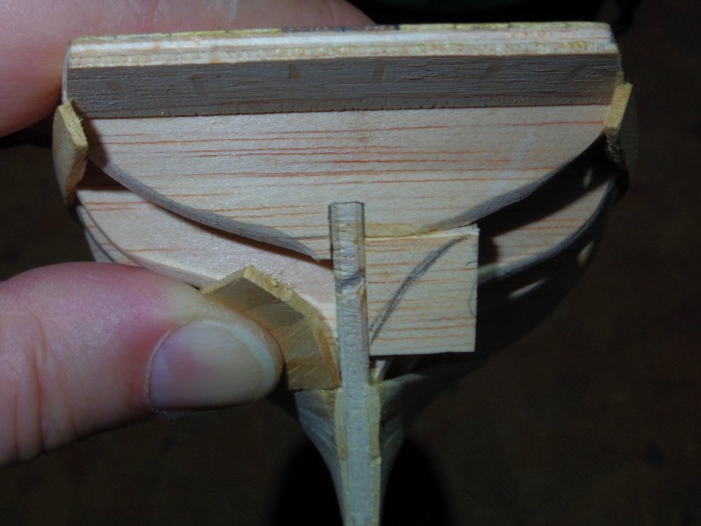
It's wood and you're only really worried about the outside surface, it's repairable.
Carve out the areas in purple until almost the depth of your planking, select wood with matching grain and glue in (clamp with your thumb if you have to), sand lightly.
Remove the plank from the stern post and do it all in one piece (edge glue 2 or more pieces to make a broad plank if you have to). I think it will look better if the grain runs parallel to the aft edge but choose what pleases you.