


iMustBeCrazy
-
Posts
840 -
Joined
-
Last visited
Content Type
Profiles
Forums
Gallery
Events
Posts posted by iMustBeCrazy
-
-
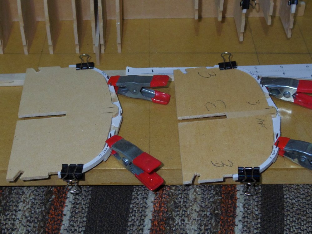
I realised that by forming the frames before the jig is glued it would be easier to clamp them using the moulds to set the shape.
Note that the futtocks only follow the mould as far as the floor head.
- oakheart, thibaultron, mtaylor and 1 other
-
 4
4
-
1 hour ago, oakheart said:
When joining those dots what determines the amount of curve between stations?
The shape of the hull
")
Possibly the easiest way is the tape trick (see pic) the tape shouldn't have any kinks and should lay flat BUT it should approximate the outer surface of the plank you are trying to make (inner surface for clinker). Mark the edge of the previous plank at each frame and the stem and transom.
Use the tape to make a template with your curves, use your calculated plank widths at each station to get the other edge.

- Wintergreen, oakheart, mtaylor and 1 other
-
4
-
46 minutes ago, oakheart said:
I still have not fully understood the use of the fan yet, more reading required here.
This bit is easy to explain, the fan is just a way of marking off your divisions on your tick strip.
On the fan mark your lines 0 through 8. Mark the measured distance on the tick strip. Hold one mark on line 0 and the other on line 8 (it doesn't matter how skewed it is) the other lines give your equal divisions.
Remember that your planks will need to be slightly larger than that indicated by your division as you are measuring the inside arc. This is more relevant in real life but be aware.
- mtaylor, Keith Black and oakheart
-
3
-
19 minutes ago, Gregory said:
Most seem content to show it as one big piece
It depends on what you are modelling.
Fincham (ca1820) gives us this description.
The transom in launches and clincher-built boats has its aft side on one surface, and well with the rake of the after part of the post; but in barges and pinnaces it is in
general in two parts, the upper part lapping over the aft side of the lower, and projecting abaft it, to form a moulding on its lower part, well with the lower part of the land strake;and in addition to this mouldng, formed by the projection of its lower edge, one is likewise worked above by another projection, worked out of the upper piece, well with the lower part of the sheer or upper strake.
The transom in launches and clincher-built boats are therefore always let in their thickness from the after part; and in barges, pinnaces, and yawls, from the fore part, it is in general fastened to the post with nails, in addition to the ring bolt and gudgeon.
So the transom of almost any boat other than a Barge or Pinnace will look like one big slab but was probably made up of two or more pieces.
- oakheart, mtaylor, Keith Black and 1 other
-
4
-
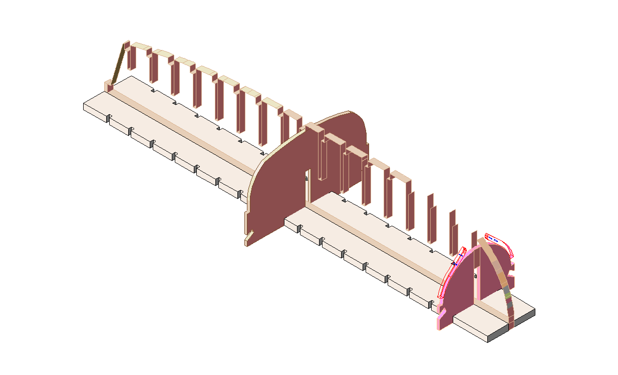
I've decided to make a change to the jig. Instead of just gluing it to a board as I have previously I'm going to glue a notched strip either side of the false keel and notch the moulds to fit.
This should allow better access to the inside during construction.
Please forgive my attempt at 3D, the false keel........:
- oakheart, thibaultron and mtaylor
-
3
-
51 minutes ago, oakheart said:
Hmm, all I want is a good looking model, will it make a difference which way I go?
In that case, not really. You're looking good.
What does it look like inside?
25 minutes ago, Wintergreen said:a friendly advice
And good advice, I'm contemplating adding an additional mould (station i) to support the shape of the bow but it's not easy from a 2D drawing.
- Keith Black, mtaylor and oakheart
-
3
-
1 hour ago, AON said:
I find it all very confusing as most overlap in length, number of oars, and even dual use of names... and then different sources don't seem to agree.
You are not alone. It's a very confusing subject.
1 hour ago, AON said:I imagine the deciding factor might the end use assigned to the design.
Sort of. I think.
1 hour ago, AON said:Where might that be listed?
It won't be.
Many of the descriptions you read are authors opinions stated as fact, even though there is often evidence to the contrary. Eg. there are contemporary sketches of six oared jolly boats.
Function would have varied depending on the size of the ship and probably the Captains disposition.
And as always, There will be exceptions.
Fincham (ca1820) gives us this description. It's certainly not 100% correct but it's a start.
The principal boats for attending upon ships are: launches, long boats, barges, pinnaces, cutters, yawls, jolly boats, life boats, and gigs or galleys.
The launches, long boats, barges, pinnaces, and yawls, are carvel-built; and cutters, jolly boats, galleys, gigs, and life boats, are clincher-built.
Launches are in general from 34 to 59 feet in length. They are for watering and carrying stores to the ship, and are sometimes armed and equipped for cruising
at short distances; they are mostly fitted to carry one twelve-pounder carronnade, and sometimes fitted with swivel stocks.Long Boats are seldom or never employed for the use of British ships of war; they are sharper and wider than launches.
Barges are generally 32 and 35 feet in length. These boats are for accommodation, pincipally for carrying flag officers and captains; and are lined and panelled above
the thwarts, all fore and aft, that they may be richly decorated, if required.Pinnaces are 28 and 32 feet in length. These boats are for similar purposes as the barges, but to carry officers of less rank; they are not therefore fitted up in quite so
neat a style, as they are lined and panelled no farther foward tnan the stern sheets.Yawls are in length 26, 25, 18, and 16 feet. These boats are for carrying light stores, provision, and passengers, to and from the ship. To the smaller class of ships,they answer all the purposes of a launch.
Cutters, Jolly Boats, Galleys, Gigs, and life Boats are clincher-built, that they may be made as light as possible.
Cutters are in length from 32 to 16 feet; they are used for various purposes that are common to ship's duty, though sometimes 32 foot cutters are supplied to ships instead of a barge,
and used for the same purposes; and sometimes the shorter boats are called and used as jolly boats.
Galleys are from 28 to 36 feet in length; they are used in enterprises and expeditions against the enemy, and against illegal trade.
Gigs are in length from 16 to 27 feet; they are for swift rowing, and are supplied to ships when light boats are required.
Life Boats are from 16 to 22 feet in length; they are for landing in surfs, performing enterprises and boarding ships, and for saving men that fall overboard,
-
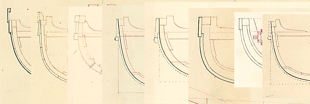
7 hours ago, oakheart said:
Comments please.................
Make up your mind now as adding a rabbet will change the shape of your planks!
- mtaylor, Keith Black and oakheart
-
3
-
38 minutes ago, oakheart said:
build I think I will opt for, counting left to right No. 7, it's simplest to make
And it could be right.
I've added ID's and dates to post 21.
58 minutes ago, clearway said:and here is me thinking we Keiths had problems with deciphering our Terrors!
Yeah, you guys have bucket loads of info compared to us.
- clearway, mtaylor, thibaultron and 1 other
-
4
-
1 hour ago, Roger Pellett said:
maybe it’s the rig that you posted but that drawing is 110+ years later than the one that Allan posted.
Roger, when you add the 'hole' in the seat with the hole in the transom it really looks like it.
Oops, just found this one, same artist same time same rig.
-
1 hour ago, mtaylor said:
Looking at post #21, It makes me wonder if every contractor for boats had their own way of doing things which would make it tough to sort out which one was correct the Bounty at the point in time of the mutiny.
Mark, I have no doubt that every shipwright had his own way of doing many things but these are Admiralty drawings presumably saying 'we want it built this way'. So the question might be 'did every draughtsman have his own way of doing things?' or was there actually a reason for the variations? I don't know. I think these eight are the only launch drawings that show any planking details and they basically fall into two groups, sheer strake and sheer wale (thicker sheer strake) with more or less detail/accuracy.
As for the Bounty launch short of the wayback machine or discovering that the Tahitians had invented photography we can only make educated guesses about much of it. What we're aiming to do is get as close as we can without the commercial considerations of kit manufacturers. Ultimately it is extremely unlikely we'll get it anywhere near 100% right but hopefully we'll avoid obvious errors.
- thibaultron, oakheart and mtaylor
-
3
-
36 minutes ago, oakheart said:
today I was thinking about what Bligh and the crew may have done
Canvas catches the wind, often in undesirable ways.
I would guess the canvas screen was around a foot high with another foot below. And the rain catcher, a canvas sheet held by four men in the shape of a scoop. They probably had a low piece of canvas as a sun shield that they used to catch water when it rained.
- mtaylor, oakheart and Keith Black
-
3
-
-
7 hours ago, allanyed said:
I found the following drawing called Seamen Painting a Jolly Boat by Lt. Gabriel Bray of the Pallas which he did in 1774. It looks like a four oared cutter to me but I may be dead wrong.
Allan, I don't think you're wrong. However there are a few strange things in the drawing. First off I think it should be titled Boys Painting a Jolly Boat given their height, second, there are two row locks missing and it probably should be single banked, third, do I see provision for three masts?
But it was actually a very good fit when I overlaid my 16ft Cutter:
-
-
-
I guess I may as well post the rest of this:
The thwarts of boats are loose, and fixed ; generally three are fixed, and are called the fore, main, and after thwarts ; those fixed are commonly kneed at each
end; to carvel-built boats, in general, the main, with two iron knees, and the fore and after, with one, which have two nuts and screws or forelock bolts
through the side, one of them through the gunwale, and two up-and-down bolts through the thwarts. When the knees are wood, which is most commonly the
case in clincher-built boats, they are fastened with nails, which are in general rivetted on roves or washers.To strengthen the fore part, and unite the bow's, two hooks are in general placed across the bow, one on the gunwale, and one at the upper part of the wash
strake; in large boats, when they are attached to the gunwale, they are generally fastened with two bolts on each side; and in others, commonly, with nails;
if wood hooks are used, the nails are driven from the outside, and rivetted on roves.
And abaft, to strengthen the quarters, knees are likewise brought against the transom, one on each side, commonly at the gunwale and wash strake.The internal fittings of boats are different according to their class and service.
In launches, the footwaling generally extends from the keelson to the rising; to some boats, to about the height of the floor-head; while others have bottom
boards, only to fix and unfix. The bow and the stern sheets are likewise not only fitted differently, according to the class of boats, but frequently according
to the taste of the captain, officer, or person for whom they are intended; some times with regular platforms, and frequently with gratings only.The internal fittings of boats generally are of too trifling a nature to require description; and to explain their detail would be more extensive than important; since a very
moderate attention paid to them would be sufficient to become acquainted with all the particulars relating to them, and would fully answer the requirements of
the student.It's a pity he never guessed that future students would be unable study a genuine contemporary boat.
-
-
Turning my head to thoughts of planking.
John Fincham has given a description of building a Launch in his various books (ca1820) and I've been trying to get my head around his description.
The garboard strake is layed into the rabbet of the keel, and is fastened as other strakes, with two nails in each timber, except when it widens aft, when it has sometimes three.
The binding strake is placed to be a parallel distance up from the lower edge of the landing strake, and has its upper edge reduced in thickness, for this strake to lay upon it.
The landing strake is then brought on, and the sheer or upper strake, when the gunwale is on, the upper edge of Which corresponds with the upper part of the gunwale,
to lap on the landing, according to the breadths, as in general shewn on the draught. The space between these strakes and the timbers, which is left by their lapping on
each other, is in general filled up by small fillings; and the strakes are fastened with two nails in each timber; and the upper edge of the upper or sheer strake is nailed to
the gunwale.The gunwale, which is the upper boundary of the permanent part of the boat, is in general composed of two or more pieces, scarphed together with a vertical scarph,
from about 9 to 12 inches in length; and has its upper side well with the sheer or upper strake. The heads of the timbers are shaped on the inside, from the lower side of
the gunwale to about one-eighth of an inch at the upper part, and the gunwale is scored over them.Above the gunwale is fixed wash strakes, sometimes permanently, and at other times to fix and unfix. When permanently, chocks are let through the gunwale, to extend
down to the upper part of the landing strake, inside, and up to the upper part of the wash strake, for fastening them to the chock, and are spaced so as to form the rowlocks,
with additional ones on the bow and quarter, according to the space.The wash strakes lap on the outside of the sheer or upper strake, and are fastened to it, in addition to the fastenings in the chocks.
They have likewise to support them, sometimes, a narrow strip, called a feather band, nailed to their upper edge, inside; but most commonly
they are lined quite through.On the outside, close under the wash strake, is fixed a piece, rounded to form a fender; and likewise a similar piece, only smaller, is fastened on the land strake, close to
the lower edge of the sheer strake, called a land rail.Inside, to a proper height and for supporting the thwarts, is fixed a strake, called the risings; this strake is in general nailed to the timbers, and the thwarts are let in a small distance.
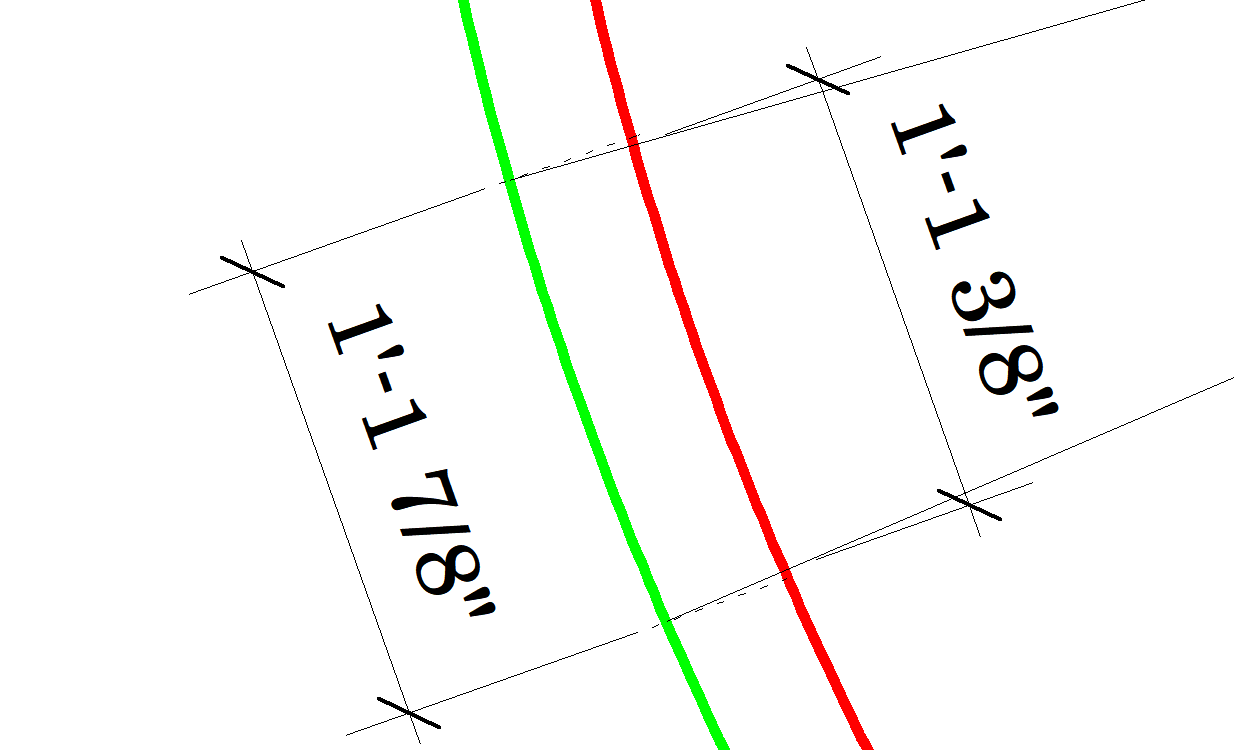
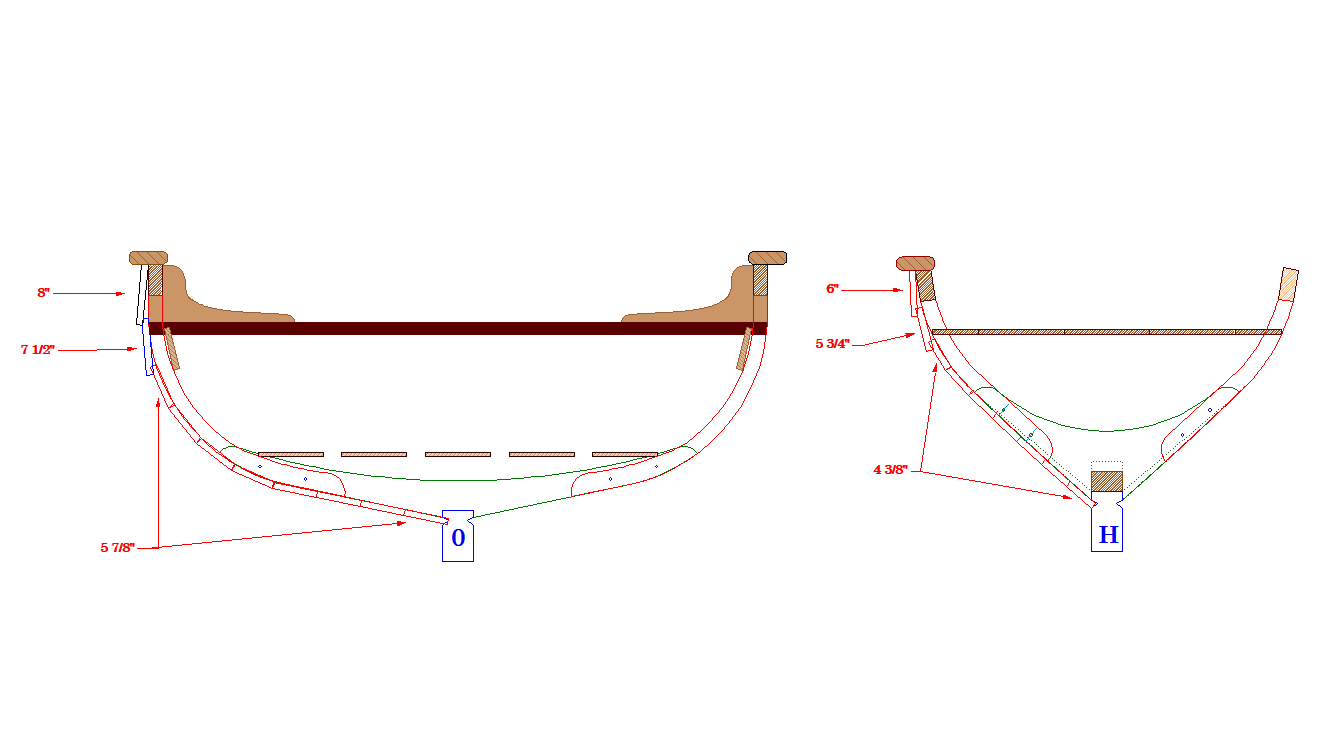
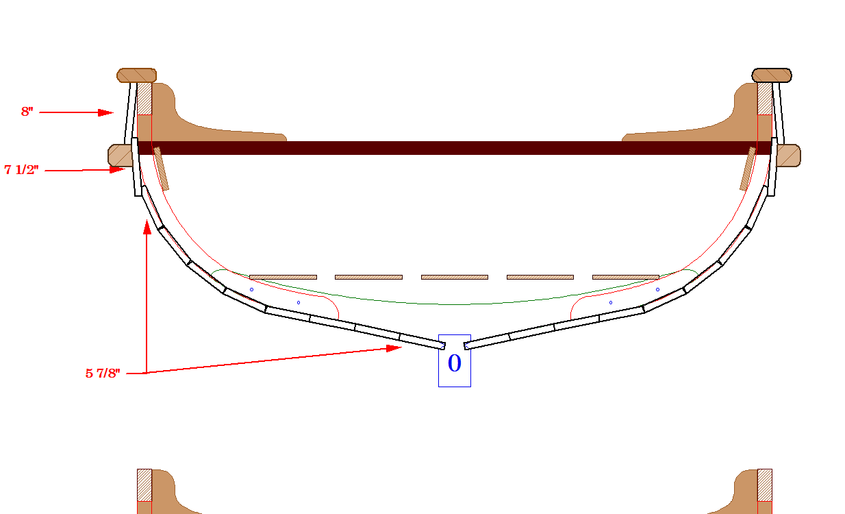
I made the following drawing based on Finchams description and ZAZ7344 which I think is right except Fincham suggests the Landing strake laps over the Binding strake.
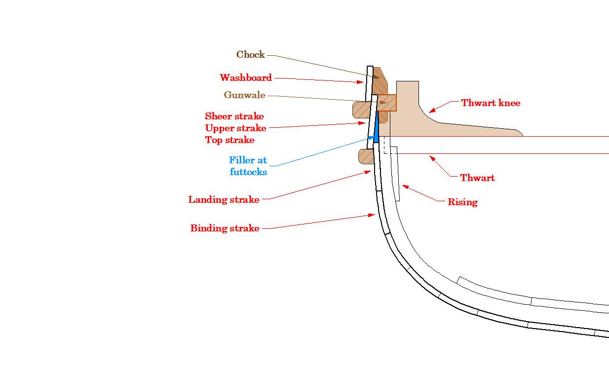
I then attempted a drawing based on ZAZ7361 and found that the curvature requires that overlap (NOTE. I've left the washboard off).
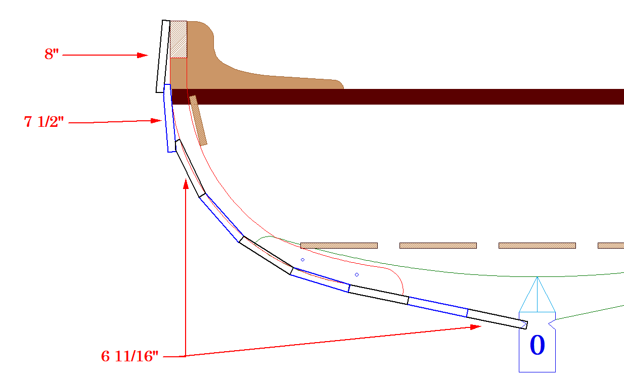
Given how much the planks would need to be hollowed out I think I'll redraw it with 8 x 5 7/8" planks.
Oh well, back to the drawing board.
Edit, it looks better:
-
Jolly boat is more a nickname than a description, the smallest boat on the ship and usually a cutter. But there will be exceptions
- mtaylor, AON and Roger Pellett
-
2
-
 1
1
-
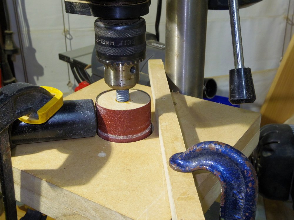
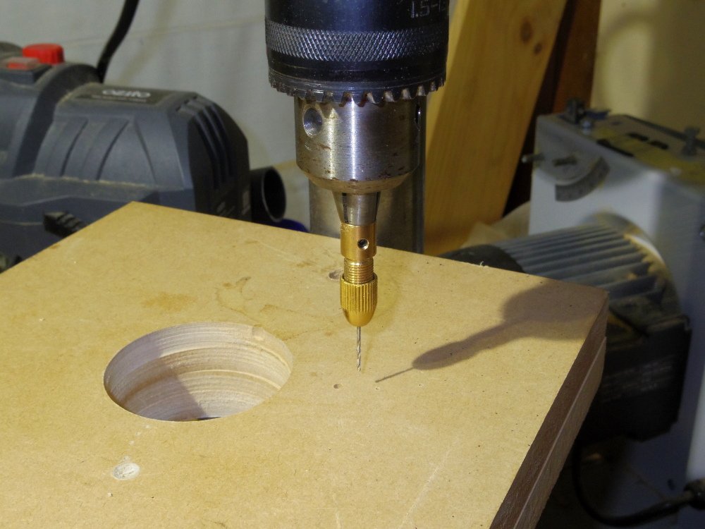
3 minutes ago, oakheart said:
Does the diameter of the drum make a big difference ?
Only if you're doing inside curves like my futtocks. The contact area doesn't change much. Mine is about 40mm.
Make sure you can grab the far end before you have to stop pushing and wet fingers helps prevent slipping. Go slow and take a little off at a time.
- Keith Black, mtaylor and oakheart
-
3
-
22 minutes ago, oakheart said:
Question : has anyone done anything like this?
All sorts of things.
The drum is two (more or less) bits of MDF cutout with a hole saw, drilled and tapped, epoxy applied to the bolt and mating surfaces, screwed on to the bold and lightly tightened together like lock nuts. The head of the bolt is cut off. Once cured it is fitted to the drill and sanded while spinning with a bit of sandpaper on a square block. Sandpaper is then glued to the drum with contact cement, you could do two different grits at different heights. No overlap and as small a gap as you can. The fence must be square, a bit of aluminium extrusion would be nice but wood will do if square.
A vacuum to suck up the dust and clean the drum and you're done.
- oakheart, mtaylor, Keith Black and 1 other
-
4
-
All floors and futtocks have been centre punched (alright, pricked) and are ready for drilling.
Centre 'punch' in action:
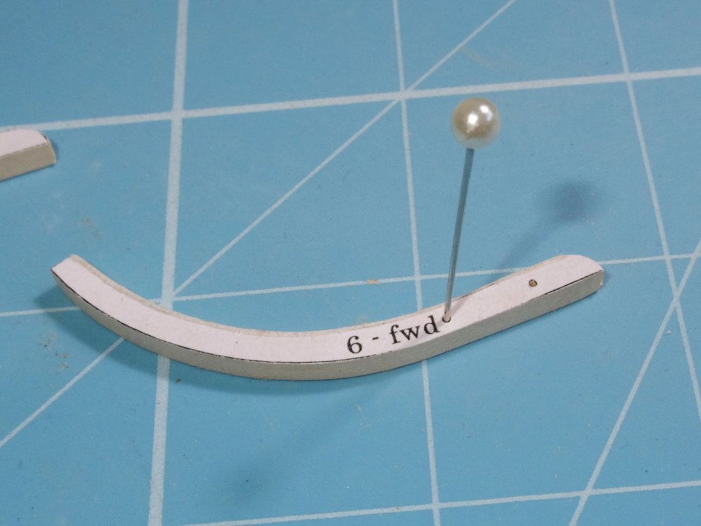
How I drill tiny holes:
- oakheart, mtaylor and Prowler901
-
3
-

Bounty Launch by iMustBeCrazy - 1:16 - SMALL
in - Build logs for subjects built 1751 - 1800
Posted
All frames glued up, just need the pins cut. Everything else just sitting there, not glued. It looks a little like a boat.