


iMustBeCrazy
-
Posts
958 -
Joined
-
Last visited
Content Type
Profiles
Forums
Gallery
Events
Posts posted by iMustBeCrazy
-
-
1 hour ago, oakheart said:
some of the barrels
You've said a few times "it's not Speedy", are you joining the other team?
-
-
6 hours ago, oakheart said:
and just to confirm my decision
And it is your decision, you are owner and master.
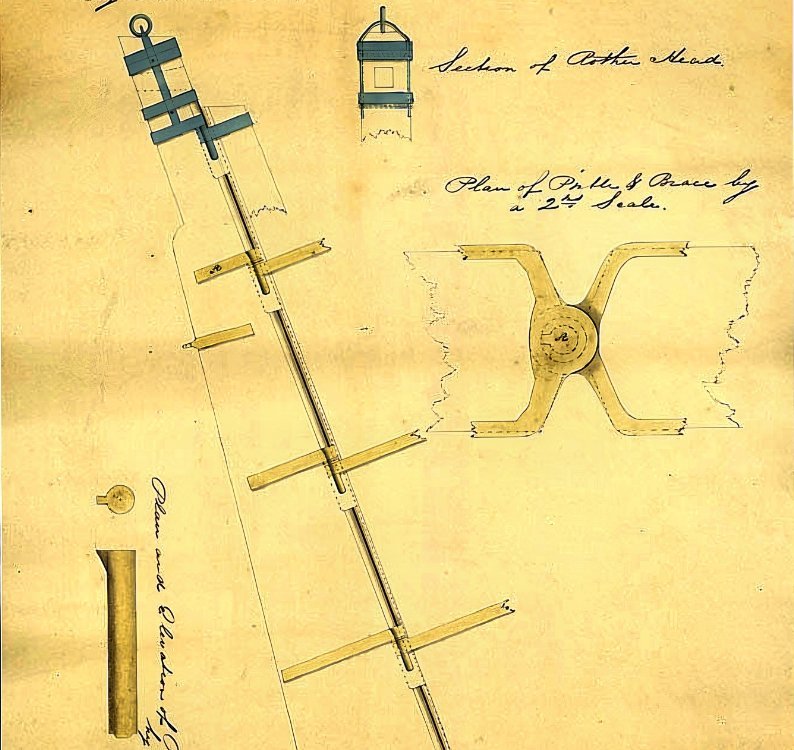
However, many things are left off the drawings, none of the 'family portraits' show catheads, horses, backstays, ............. as far as I can remember.
6 hours ago, oakheart said:What are they called, on the transom, those angled timbers.
Counter timbers. They usually stand on the wing transom and extend to the taffrail.
-
58 minutes ago, oakheart said:
I can't see any details on the drawings
ZAZ6349 (Vigilant as fitted) I think is the only 'family member' drawing that shows anything. It's quite an elaborate structure with two wc's and a number of lockers and extends all the way to the stern.
10 hours ago, druxey said:with a slot for the tiller.
I suspect they had a canvas cover over the slot and tiller.
-
-
-
-
-
-
-
2 hours ago, oakheart said:
now suddenly I making the rudder
It all has to be done sometime and the brain needs a little vacation from time to time. Sometimes it needs a little ego boost (look what I did! type of thing).
The sternpost probably tapered (say 8 inches to 6 inches) and also the rudder (say 6 inches to 4 inches)and the rudder had a rounded leading edge (see shading on drawing).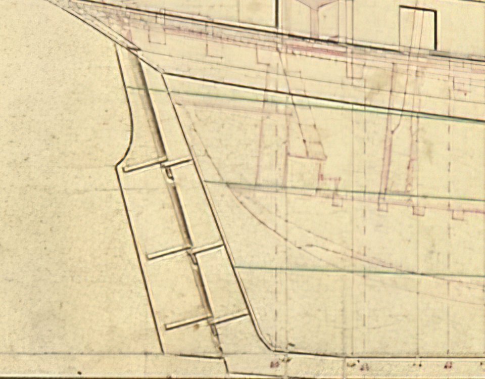
Then again I might be wrong:
https://collections.rmg.co.uk/media/543/233/l0251.jpg
https://collections.rmg.co.uk/media/544/197/l0418_001.jpg
https://collections.rmg.co.uk/media/543/699/l0330_002.jpg
It seems the only tapering was from top to bottom. Add it to the list of things drawings don't show.
-
3 hours ago, oakheart said:
Question, can anyone tell me if there would have been scuppers on a cutter like this?
I can find only one picture showing what are probably scuppers, none of the drawings show them.
However there must have been some kind of deck drainage.
It is possible that the bulwark planking had a gap at deck level but Lapwing/Speedy drawings show waterways so that's ruled out, which leaves scuppers.
Given the waterline, I would guess aft of the pumps possibly between the gun ports as below (tiny green dots).
- oakheart, mtaylor and GrandpaPhil
-
 3
3
-
-
4 minutes ago, oakheart said:
it saves cutting the rabbet which can be difficult to get right
It does. I think I'll enhance the drawing with a couple of other views and this version will be the standard one. I'll leave the complex version and may use it in a full PoF if I go there later.
-
-
-
Well, hopefully third times the charm. Yep stuffed up again, the second one's too tall. So I've deleted all my transom drawings and have started agian.
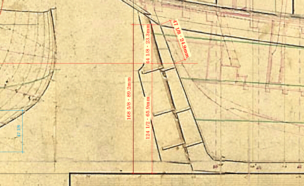
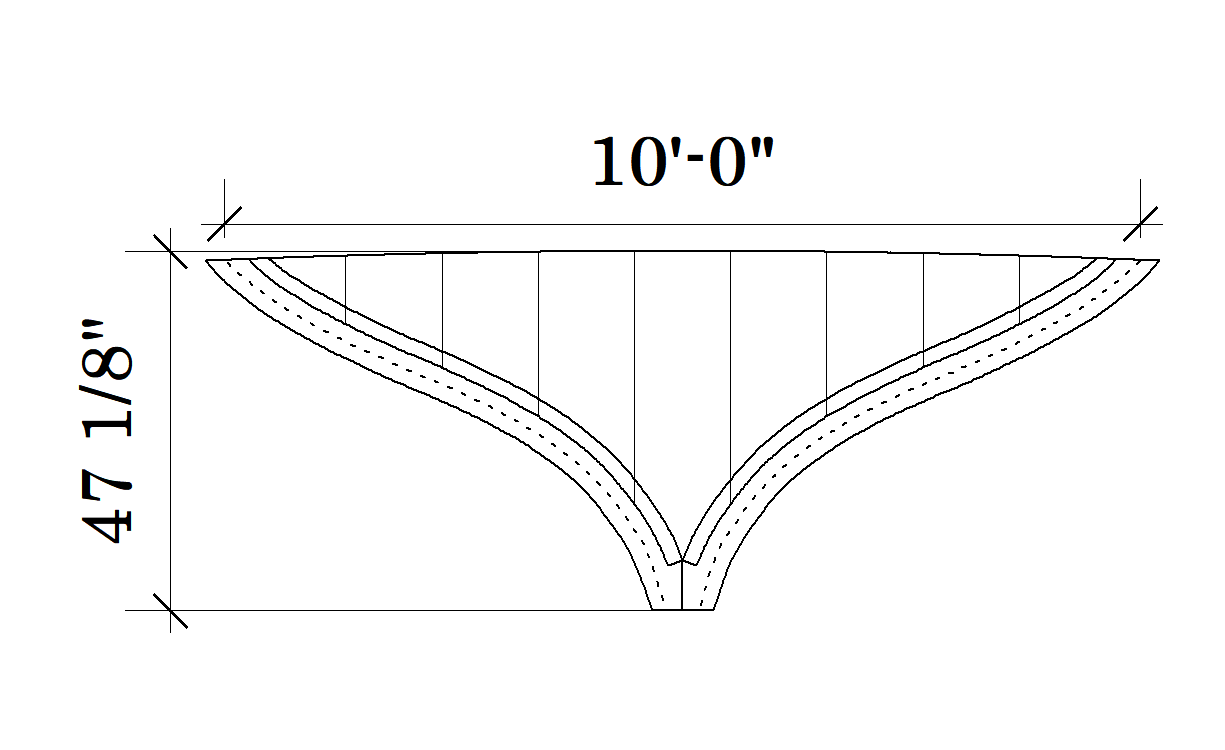
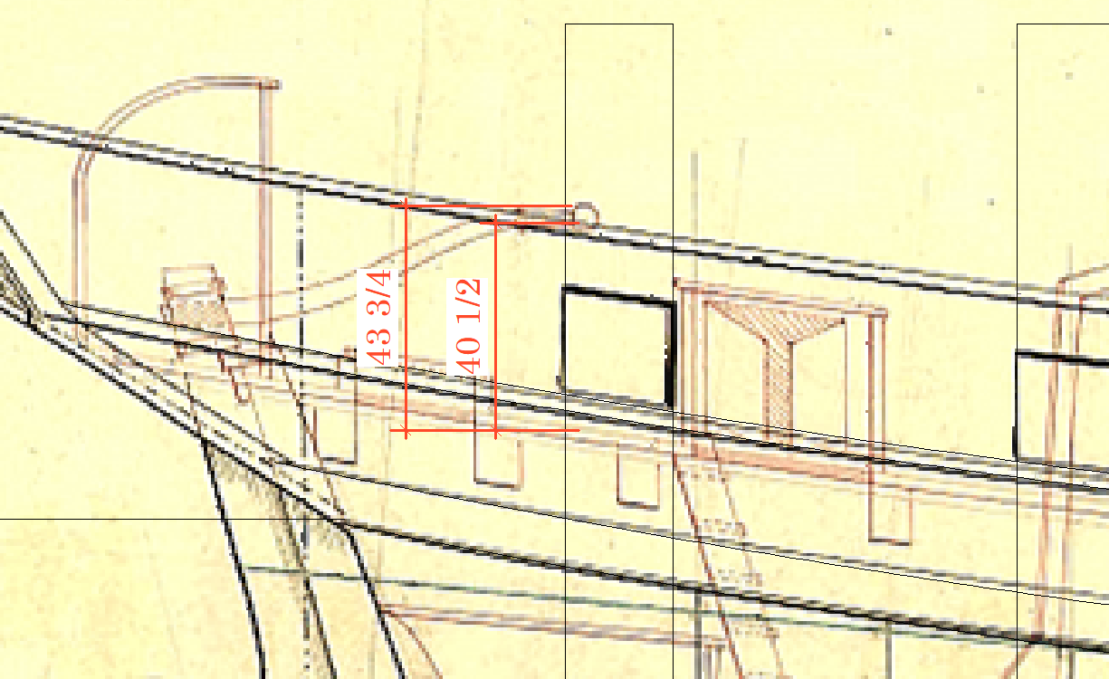
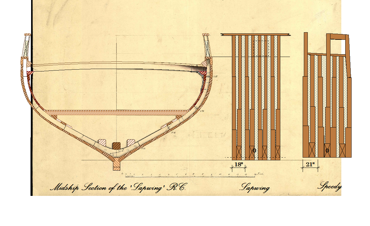
Measurements taken from the plans. These are in full scale inches and model scale millimetres and the two heights above keel have been transferred to the model.
The other two measurements are the height of the transom, vertically as drawn and the actual height.
So the drawing must be stretched vertically by the ratio 47 1/8 divided by 44 1/8 (or 24.9/23.3).
The green dashed lines below represent the as drawn, the orange as stretched.
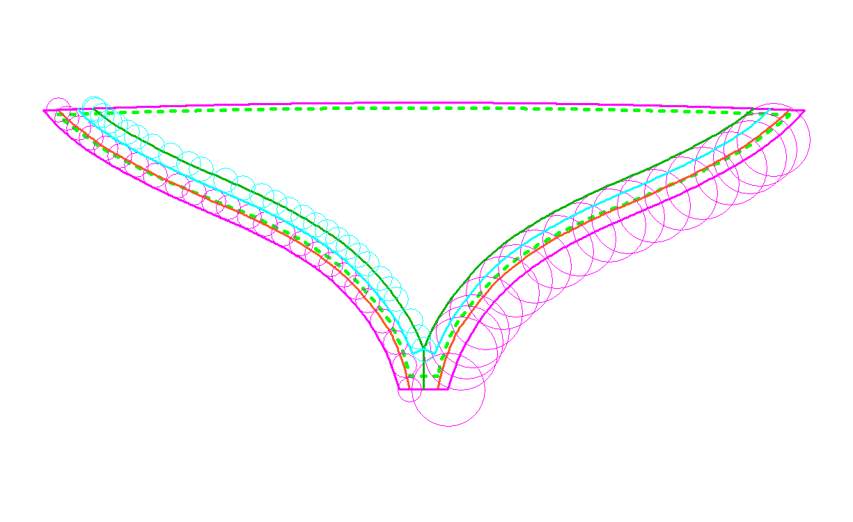
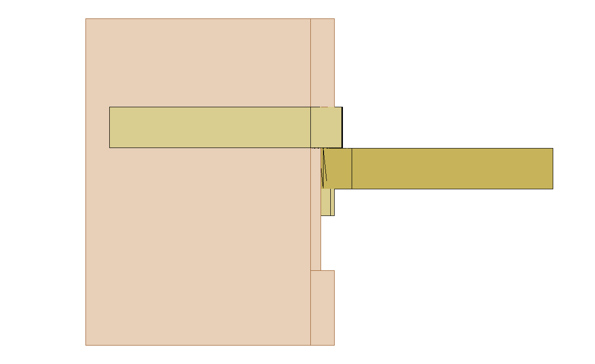
Then I have to work out the trim pieces and the rabbets. As the orange line now represents the transom inside the hull planking I need a new line 2" outside the orange line. So with the aid of the small pink circles, we get the pink line (this ignores the fact that the hull widens as it goes forwards).
This also gives the hull planking rabbet on the forward side of the trim pieces (between the pink and orange lines).
To get the width of the trim (6 inches) I use the big circles giving the dark green line.
And the small blue circles give the aft rabbet (light blue line) for the transom planking.
Oh what fun.
- mtaylor, GrandpaPhil, oakheart and 1 other
-
4
-
11 minutes ago, oakheart said:
That looks good
Thanks Tim.
New v old.
You might check out Chucks Cheerful thread ( Page 5 ), first image shows a model cutter with a similar stern and over the next few pages Chuck shows how he did it on Cheerful.
- davyboy, GrandpaPhil, davec and 3 others
-
6
-
Six hours later
")
While I wait for the glue to dry enough to sand it here's the other transom.
I posted above that I had already cut the trim pieces for this version but I still had to mill the rabbets, this was a pain. First I started milling the wrong corner, just a touch before I noticed but it will have to be patched. Second the bit kept grabbing the grain.
But I succeeded reasonably.
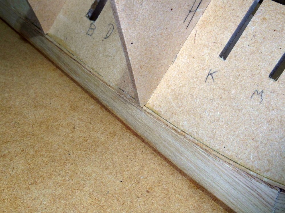
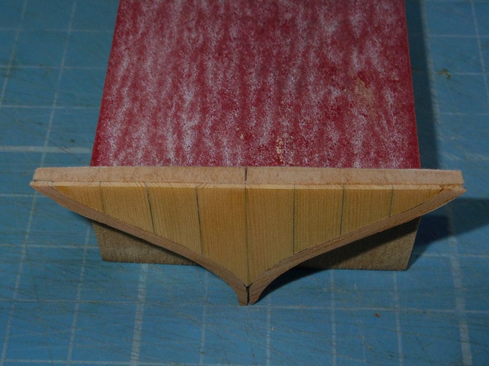
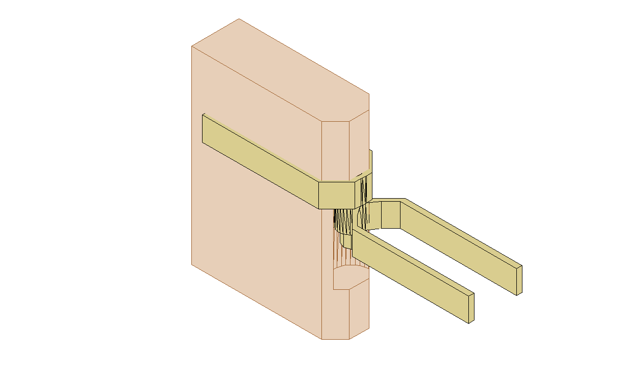
I milled (saw mill not mill mill) some timber for the transoms and fitted them with 'big' rebates. The wing transom gets mounted a little high as it gets a slightly curved top.
Rinse and repeat for the other three. A bit rough but they will be hidden and I've taken measurements for the drawings so future builders should do better.
You can see the milled rabbets, on the forward side for the hull planking and on the aft side for the transom planking.
Planked and awaiting sanding.
Disaster delayed
")
- GrandpaPhil, archjofo, davec and 5 others
-
8
-
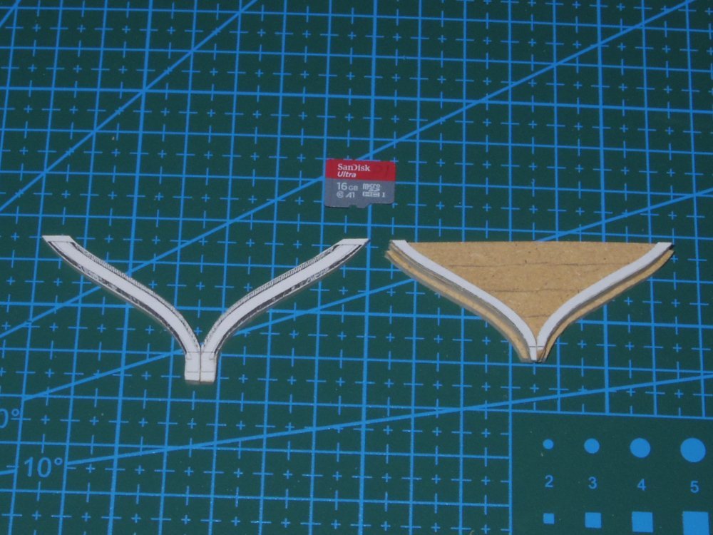
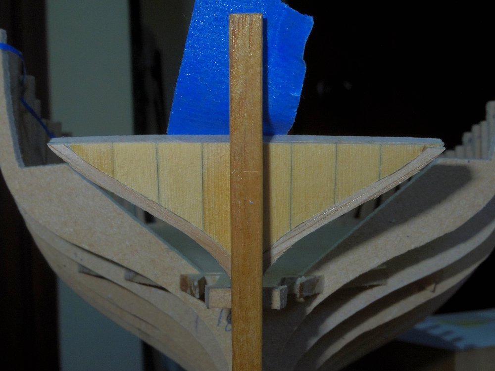
Here we go, a thing of beauty.
Pity she's wrong
 Somewhere along the line I've done something not good.
At the top where the transom meets the counter it should be 10ft wide (inside the planking) this one's 9ft 3inches.
Oh well, I was going to build another anyway.
- Tony Hunt, GrandpaPhil, davyboy and 3 others
-
6
-
-
-
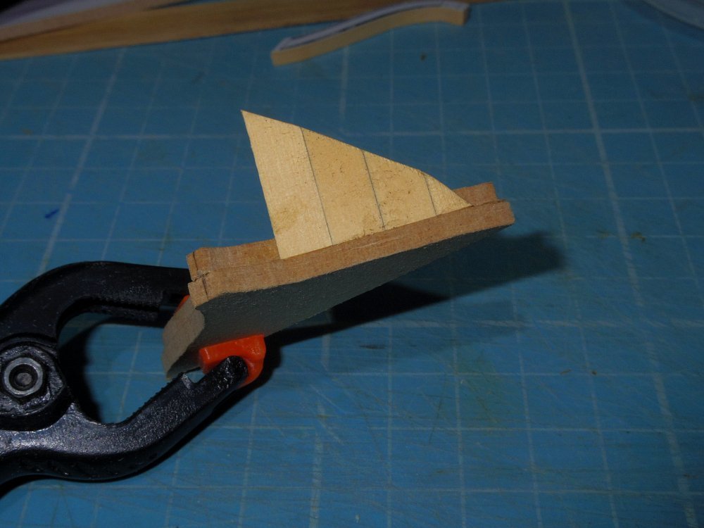
Thanks Tim.
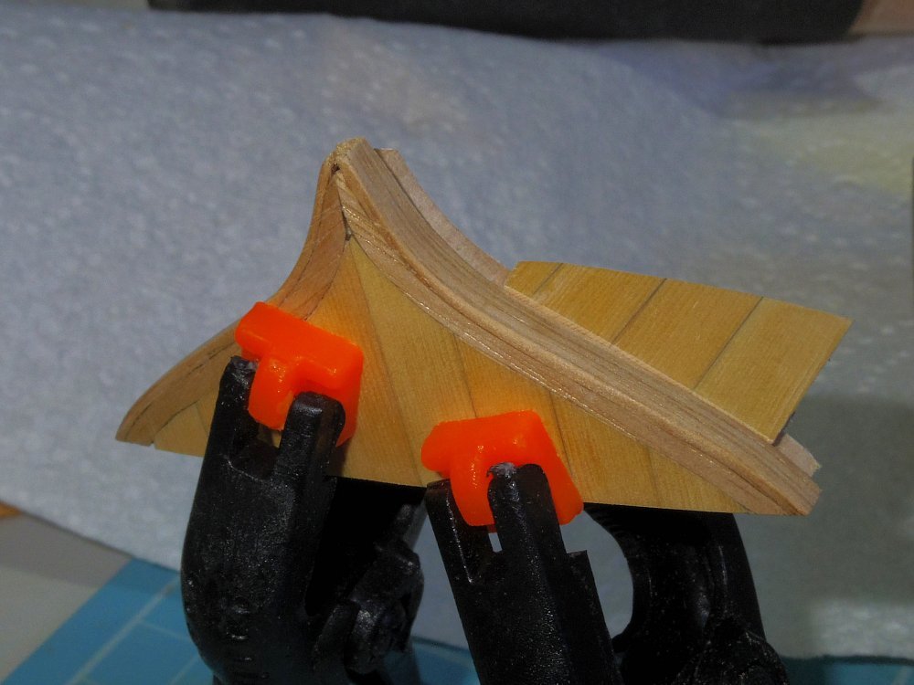
To finish off this transom a strip the thickness of the planking is glued to the edge of the transom.
When both sides are done a second MDF transom the same size as the first will be glued inside the first creating a step (or rabbet) so that the plank ends will but against the trim as in this mock-up.
- Thukydides, oakheart, AJohnson and 3 others
-
6
-
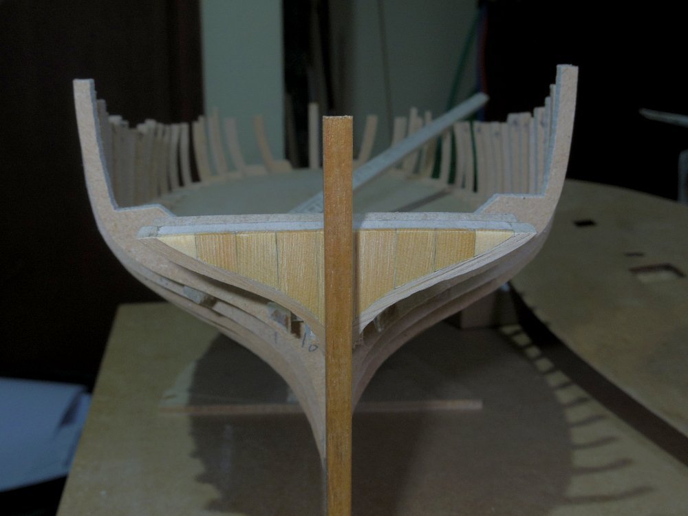
First, a couple of shots that I left out the other day.
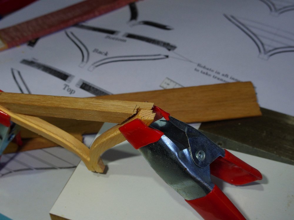
The rabbet.
And tapering the spine, from zero at the bearding line to just under the thickness of the planking at the rabbets (keel and stern post).
Yesterday my band saw died (it was only an Aldi cheapie). Luckily I had planned for that and had a spare (same but cheaper, bought on sale) but I still had a lot of setting up to do.
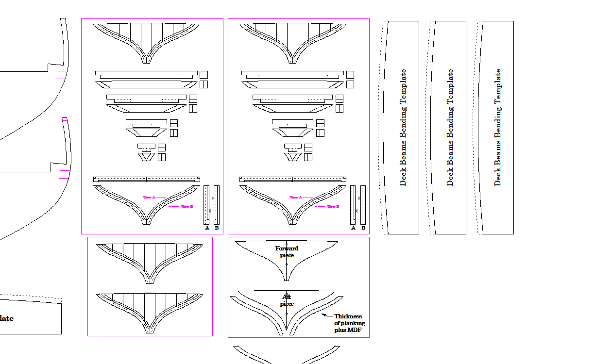
The build restarted with the transom/s. I will be building two, as built and easier.
Easier first:
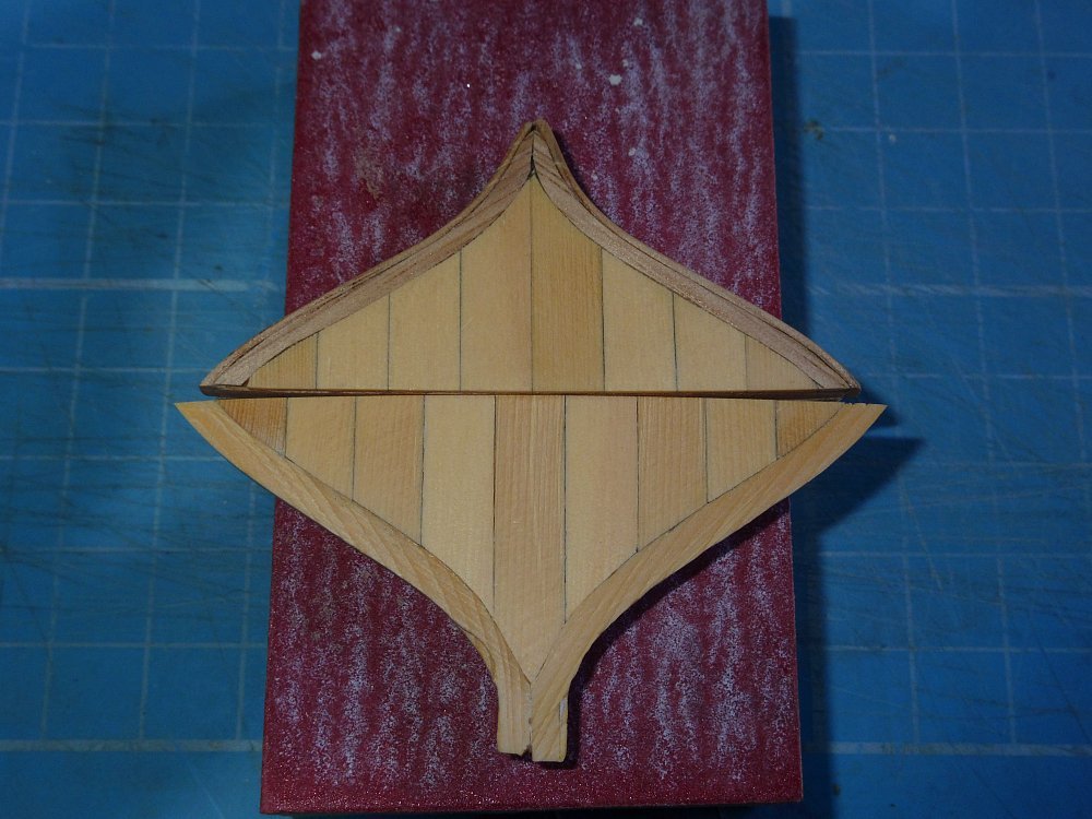
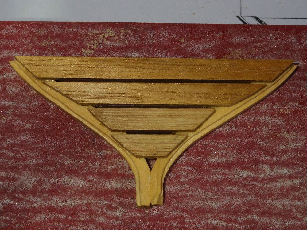
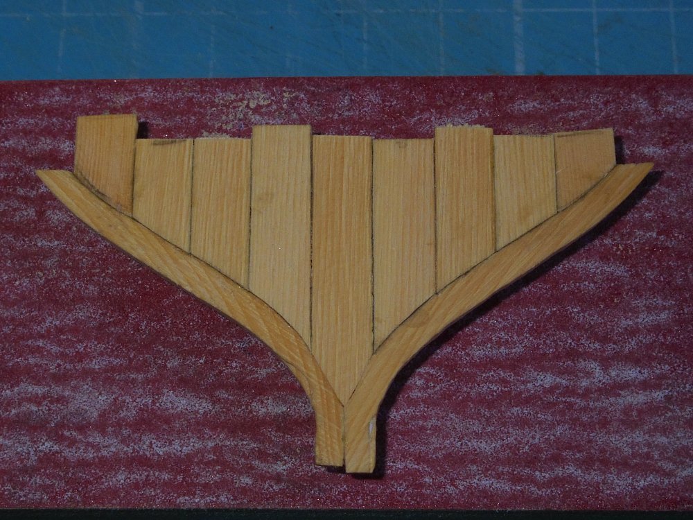
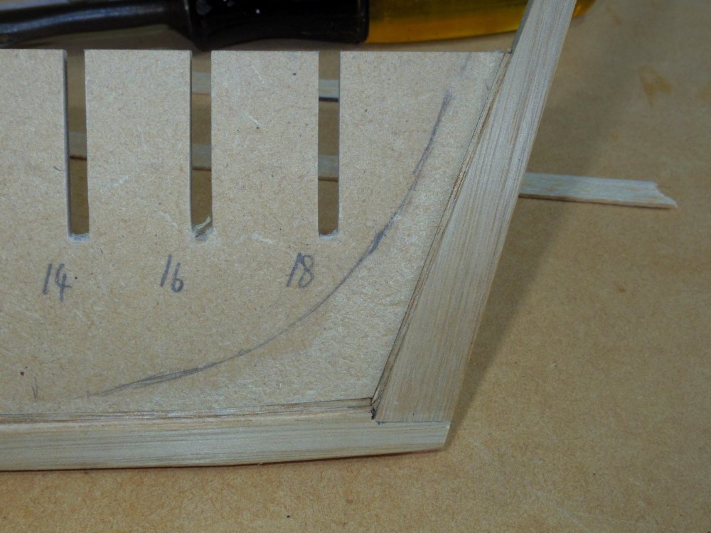
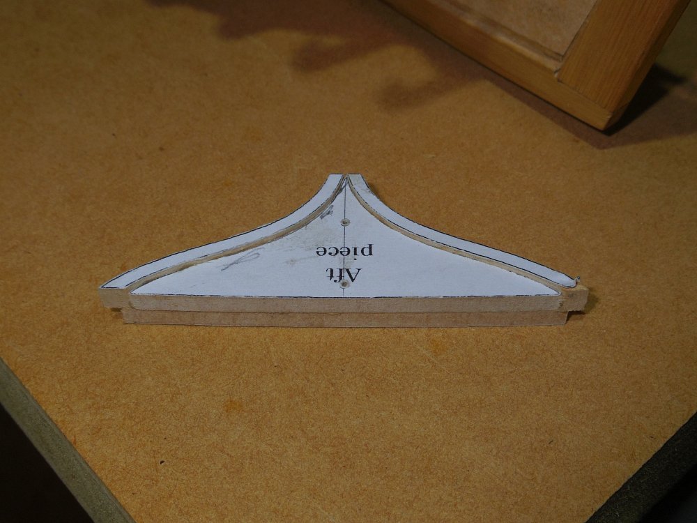
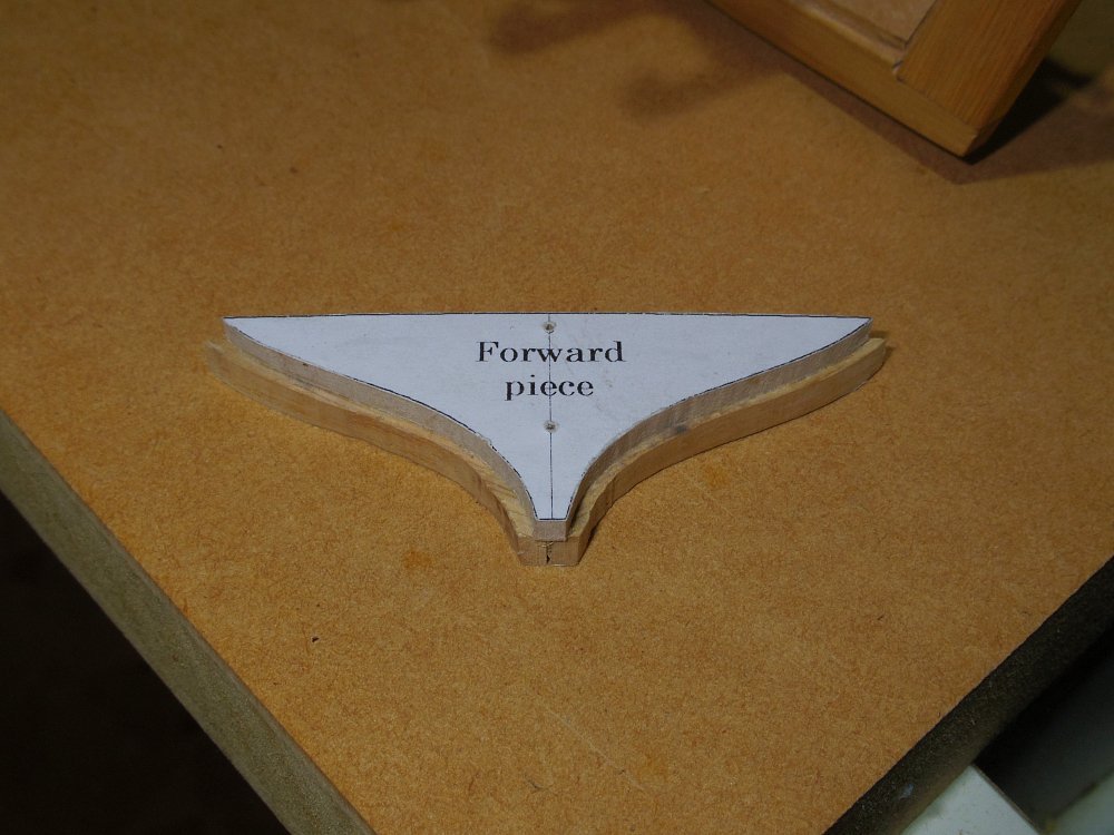
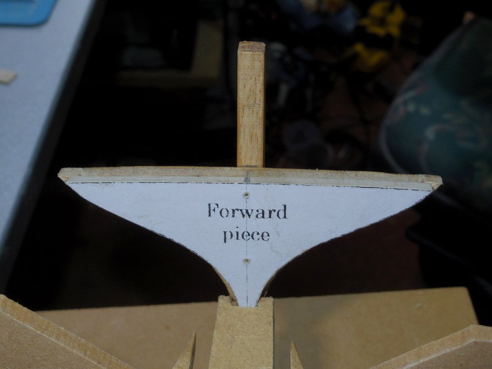
1st I cut out 2 3mm MDF transoms. Like the one on the right, the other bits covered by paper are the trims for both methods.
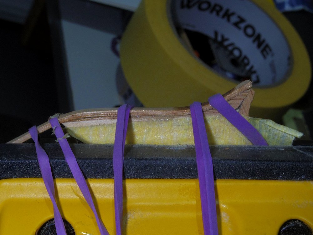
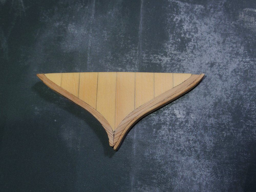
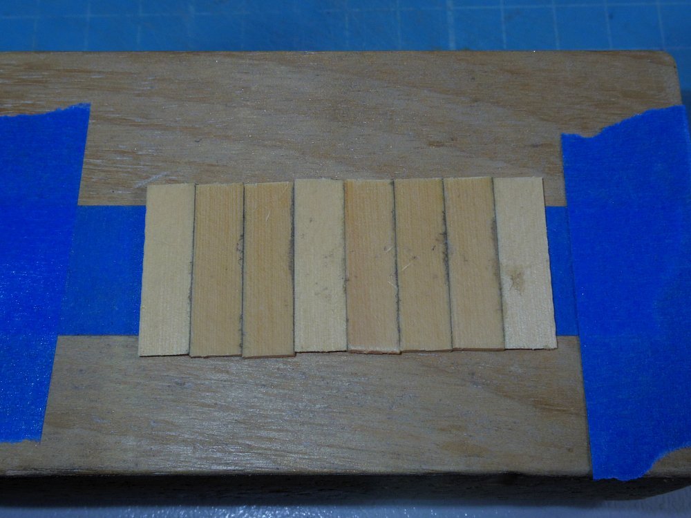
Next I made a 'raft' from 6.6mm x 1mm Huon Pine.
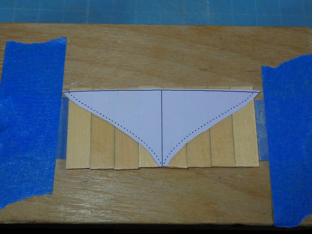
Glued (rubber cement) on the template and cut it out.
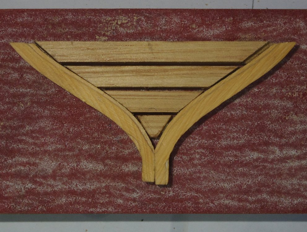
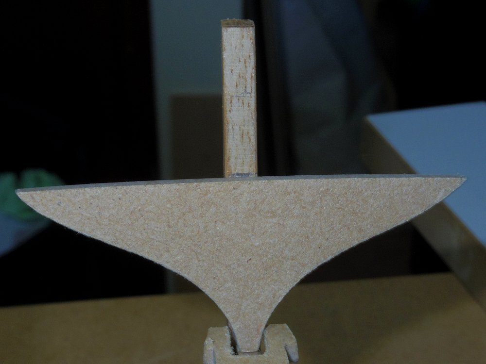
Glued the 'raft' and some trim I made earlier to one MDF transom.
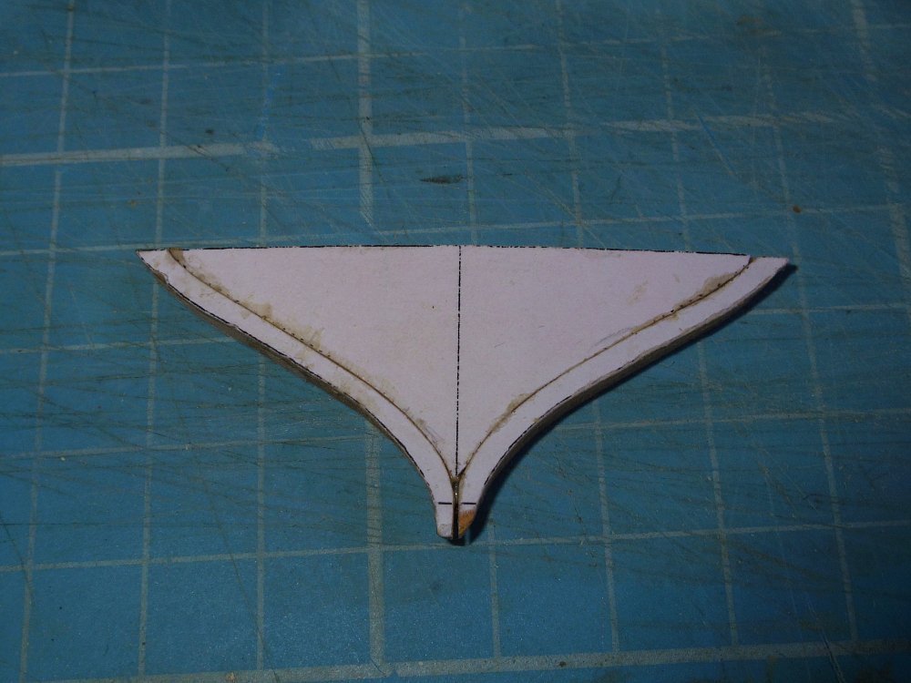
Cleaned it up a bit (look at that grain, perfect size).
Ant took a gratuitous photo of the model.
It's not finished yet, more to come.
I've also done more work on the drawings, coming soon.


HM Cutter Speedy 1828 by oakheart - from plans drawn by Bill Shoulders in 1972
in - Build logs for subjects built 1801 - 1850
Posted
I was thinking barrels of cognac, thus joining the smugglers.
There would likely be six, they should disappear through the deck (or appear to).