iMustBeCrazy
-
Posts
958 -
Joined
-
Last visited
Content Type
Profiles
Forums
Gallery
Events
Everything posted by iMustBeCrazy
-
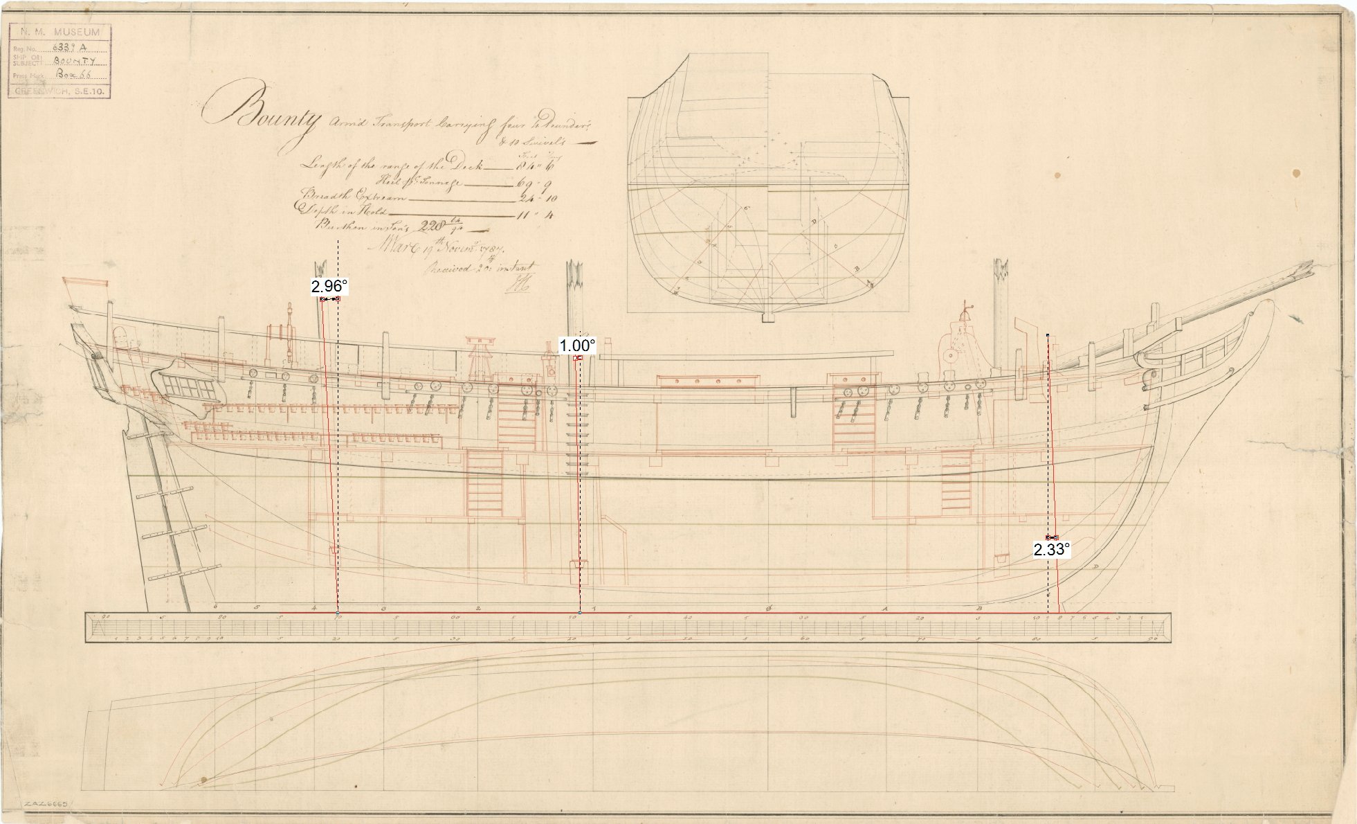
 This is what I get: Do you have this drawing? https://commons.wikimedia.org/wiki/File:Admiralty_Sheer_Draught_Ship_Plans_-_HMS_Bounty_RMG_J2028.png
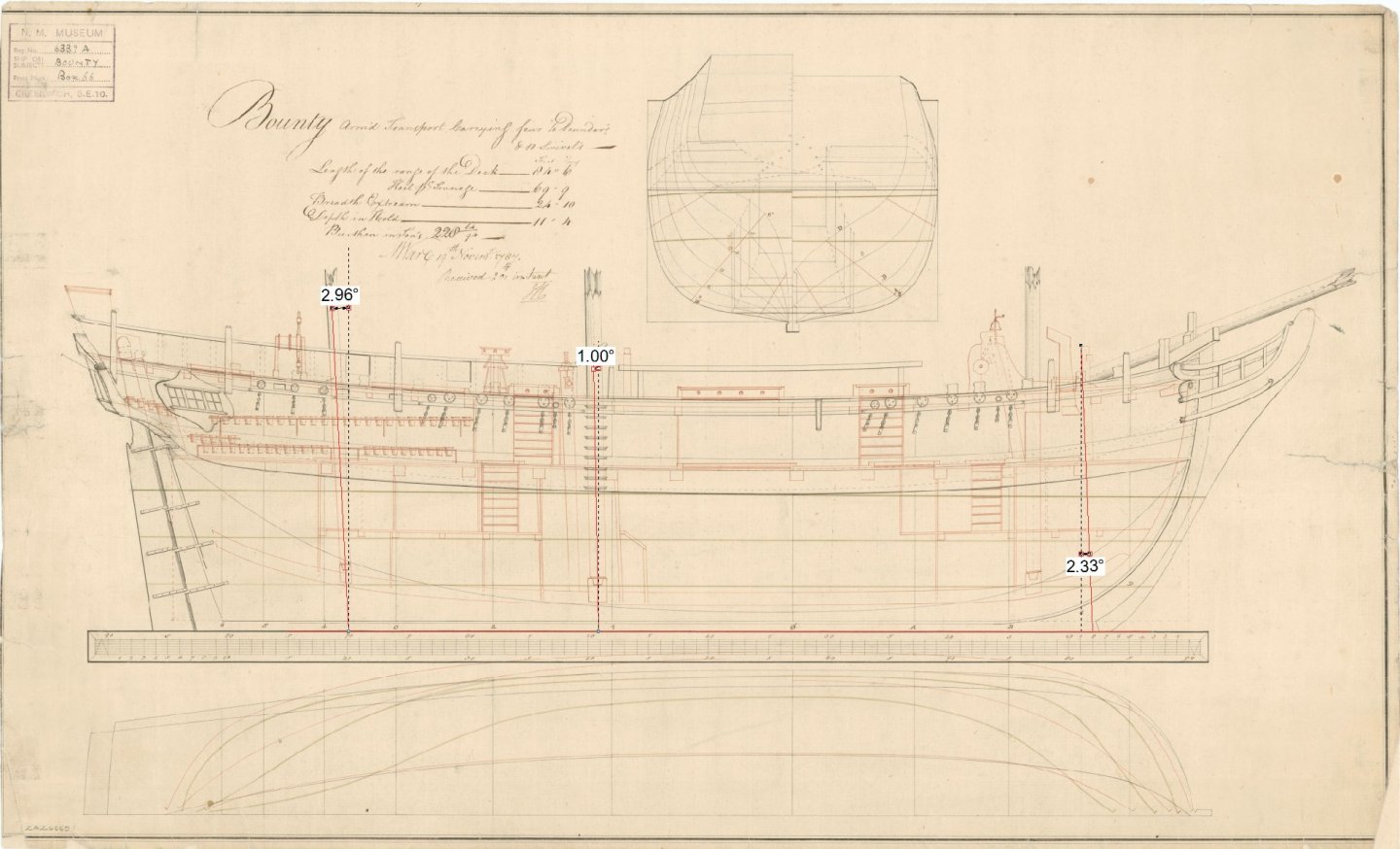
-
Some time after 1660. And 1797:
-
I didn't mind it except they never had enough extras. Hornblower never seemed to have more than a dozen crew no matter what sized ship he had and 20-30 'Lobsters' marching off to invade France wasn't very convincing.
-
I've been binge reading recently, finished the Aubrey-Maturin series and up to Jesters Fortune (book 8.) in the Alan Lewrie series. Alan Lewrie was basically blackmailed by his father into signing on as a midshipman, he never dropped below that rank. Aubrey however signed on as a mid but was 'set before the mast' for a time for smuggling a girl on board. It was a morally questionable period of time. I mean, you could kill someone 'defending your honour' even if you didn't have any.
-
Stoves/Ovens on ships in the 1600s and Onward
iMustBeCrazy replied to acaron41120's topic in Nautical/Naval History
Well, the preview says it will work, so here's what happens when I hit 'submit reply'. -
I guess the true answer would be 'it varied'. But for the davits and falls the Harriet model would provide a good example https://collections.rmg.co.uk/collections/objects/66775.html For the boat, a simple eye bolt and ring through the stern post and stem or a ring under a clamping plate for heavier boats. (Both above the CoG).
- 1 reply
-
- 3
-

-

-
Historical Fantasy. Oh, and Heresy.
iMustBeCrazy replied to Gazzarian's topic in Nautical/Naval History
I wish I had the skills you think I have The Lapwing proves your point, launched in 1816 as a Revenue Cutter, sailed to Australia in 1853 under private ownership carrying the new owner and family to Adelaide before being sold and used as a cargo vessel. Wrecked in 1856 after the Harbour Master had a larger vessel hooked to the same mooring which later dragged beaching both ships. The Lapwing broached and was destroyed. It would depend (sorry). I doubt there would be 'a lot more room', I think less crowded would explain it better. It would also vary with the size of the vessel. I've seen documents showing Revenue Cutter crew estimates varying from 30 to 60 and I have no idea how you would squeeze 60 into the Lapwing. On the voyage to Australia she had something like: Owner (and perhaps Master but I doubt it) Owners wife (just a guess as no wife is mentioned) Owners daughters (2) Owners servants (2) (but daughters may have been mistaken for servants) Paying 1st class passenger (1) Master Masters mates (2) Bosun Bosuns mate Helmsmen (2) Cook Carpenter? Other crew (12+) The above from the Bosun down is pretty much a guess. The run to Australia was pretty slow given that other vessels reported her as 'flying' so I'm guessing she stopped for a bit of tourism in Cape Verde and Cape Town. -
This might help. https://maritime.org/doc/steel/part7.htm#pg220
-
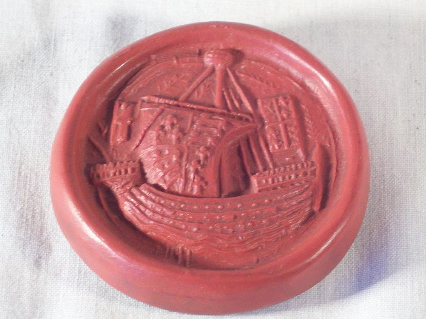
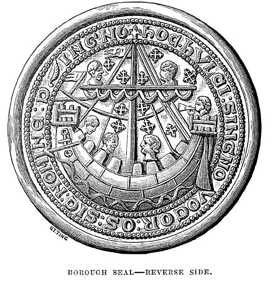
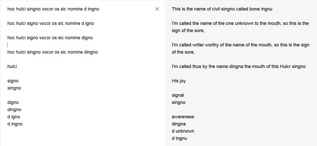
Found something, seems well researched. https://www.british-history.ac.uk/vch/sussex/vol6/pt1/pp164-166 Borough Seal Of New Shoreham (½) The matrices of the seal used by the borough in the early 14th century (fn. 72) are round, 2¾ in. in diameter, and made of latten. (fn. 73) On the obverse are the arms of de Braose, a lion rampant facing sinister (allegedly through the engraver's carelessness) (fn. 74) on a field of cross-crosslets, impaling the three leopards of England; legend, Lombardic, s(igillum) communitatis burgde de nova shoram brewes. On the reverse is the representation of a ship with human heads and cross-crosslets; legend, Lombardic, hoc hulci singno vocor os sic nomine dingno, which alludes to the name Hulksmouth used of the river or harbour in the 14th and 15th centuries and is best translated 'By this sign I am called hulk's mouth, and a worthy name it is'. The ship is said to be of the time of Edward III, (fn. 75) but the last word of the legend on the obverse suggests a date before 1324 when William de Braose surrendered his life-estate in the honor of Bramber, including New Shoreham. The lion rampant facing sinister on a field of cross-crosslets was used on its seal by the urban district council from 1894. (fn. 76)
- 186 replies
-
- 2
-
-
- keelless
- reverse clinker
- (and 4 more)
-
I was going to say that a reasonable interpretation was "This is the symbol (sign) of Hulkesmouth". But I decided to check if the Adur (the river through Shoreham) was ever called the 'Hulk'. Nope, nothing solid, not even firm. I did come up with "In 1457 the port of Shoreham is named in a document as Hulkesmouth alias Shorham. The New Shoreham Borough Seal of c. AD 1295 shows a ship in a curved form." http://www.glaucus.org.uk/Toponymy.htm That suggests the seal is almost 200 years older than the only reference to Hulkesmouth! It also leaves it open that 'hulci' might refer to the ship.
- 186 replies
-
- 2
-
-
- keelless
- reverse clinker
- (and 4 more)
-
Well, I think I've been running around in circles chasing others who are running around in circles chasing their tails. Many seem to be jumping to conclusions and using those conclusions to 'prove' other conclusions. What I haven't seen is any hard facts. Anybody know Latin? The Texas A&M University in 'an introduction to Nautical Archaeology' https://nautarch.tamu.edu/class/316/hulk/ gives hoc hulci signo vocor os sic nomine digno (by this picture of a hulk I am called mouth thus by a worthy name) for the text on the New Shoreham seal. Google translate gives:
- 186 replies
-
- 2
-
-
- keelless
- reverse clinker
- (and 4 more)
-
It seems that most references of 'Nef' as a ship are German and most (by far) in English are of a table ornament in the shape of a ship. This site http://www.cogandgalley.com/2011/05/nef-as-ship.html gives a publication in English as a reference but that too may use German references. My next post will be back on topic (I think).
- 186 replies
-
- 2
-
-
- keelless
- reverse clinker
- (and 4 more)
-
You probably read it somewhere sometime and it stuck in the back of your mind. The definition came from a wiki in German (https://de.wikipedia.org/wiki/Nef_(Schiffstyp), no English version exists so I've attached a PDF of the translation. Nef (ship type) - Wikipedia.pdf
- 186 replies
-
- 1
-
-
- keelless
- reverse clinker
- (and 4 more)
-
I don't know. But the ships on the seals, or at least some of them, are probably Nefs from what I can find.
- 186 replies
-
- 1
-
-
- keelless
- reverse clinker
- (and 4 more)
-
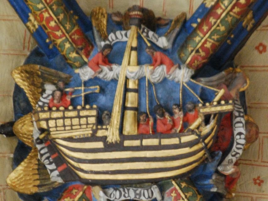
Well, I may be barking up the wrong tree but I did a bit of searching and since you include the seal of Winchelsea in your examples which appears to be a Nef as Winchelsea was one of the Cinque-Ports. Nef (ship type) ump to navigationJump to search The Nef , anciently also Naves , Cinque-Port-Schiff or to differentiate it more clearly from the general French name Nef for ship , also called Norman Nef , designates a single-masted merchant ship type, which in the Middle Ages from the 11th to the 13th century was mainly used in Western Europe Coasts and with the southern English city union, the Cinque Ports , was very common. The Nef is generally known for its depictions on city seals, the depiction of cruise fleets and the possible depiction of early Nef types on the Bayeux Tapestry . The above was translated using Chrome's built in translator. Some Model info and pics here. The more biblical images may be something else altogether. The 'whale' image (larger version here) may be fishing boat size.
- 186 replies
-
- 3
-
-
- keelless
- reverse clinker
- (and 4 more)
-
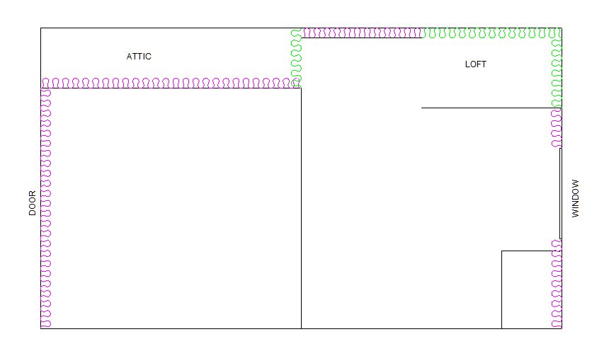
Hank, that should make a huge difference. At the moment you effectively have no roof insulation at all.
-
G'day Hank, It's hard to remember but I think you insulated all the walls (excluding the door and window), the ceiling above the sitting area including the sloping sides and perhaps the ceiling between the attic and loft. These are shown in pink below. If so, then yes you need to close off and insulate the opening to the attic. You also need to insulate the loft either as shown in green or by insulating the floor of the loft and closing the loft off like the attic but with an insulated door.
-
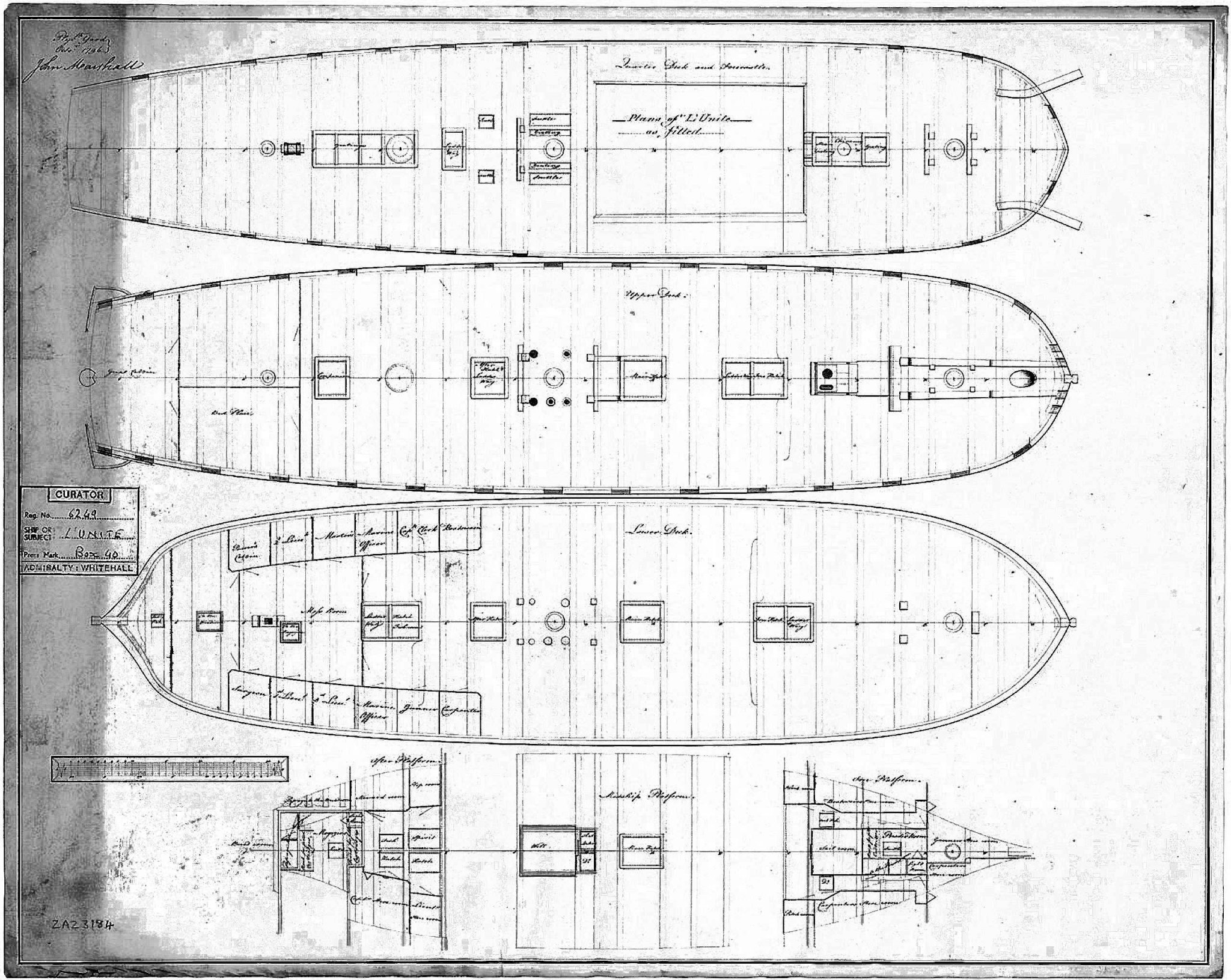
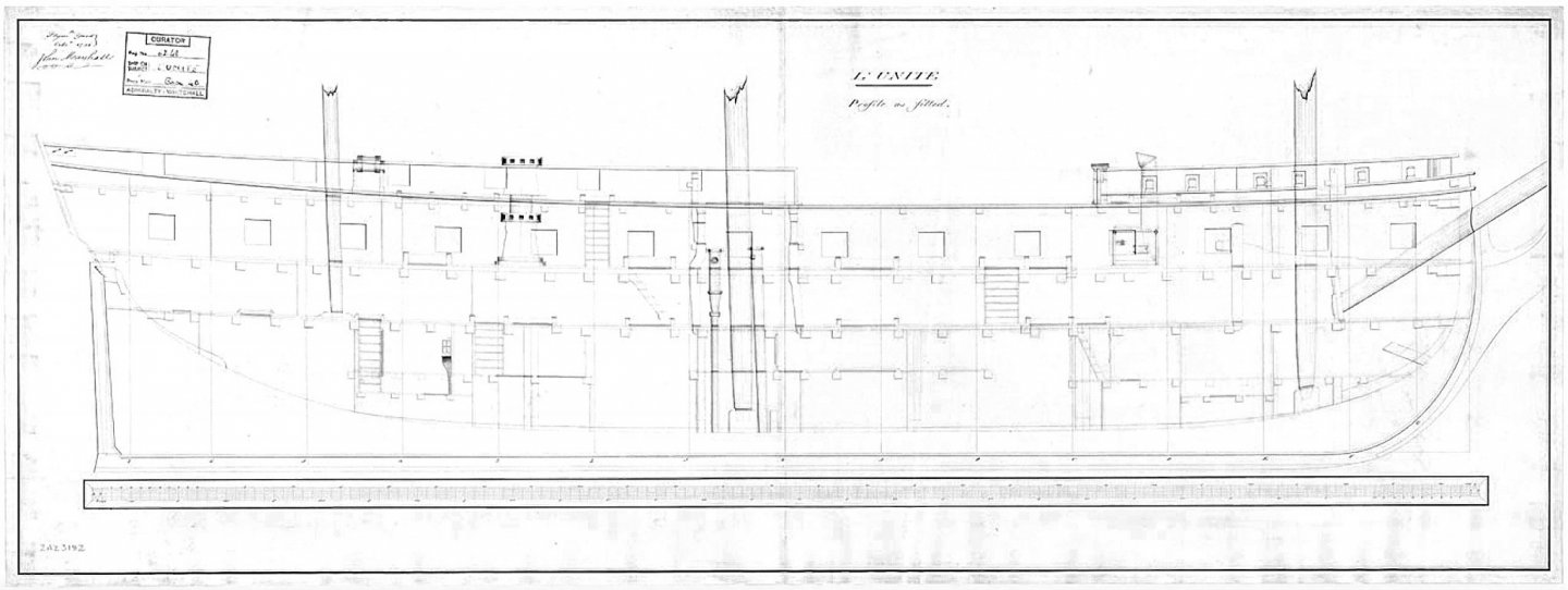
Ok, I think I've got it. In 1796 the British captured the French 5th Rate Frigate L'Unité (formerly Gracieuse) and renamed her HMS Unite (or Unity). In 1798 the British captured another French Frigate (6th Rate) named L'Unité and renamed her HMS Surprise. Confusion reigns as many sources get them mixed up.
-
EDIT: Made an error, this is L'Unite captured in 1796.

-
Cutter Grace 1763
iMustBeCrazy replied to tabycz's topic in CAD and 3D Modelling/Drafting Plans with Software
Yes. That's the way I see it. Enlarged.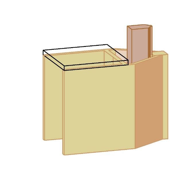
-
Cutter Grace 1763
iMustBeCrazy replied to tabycz's topic in CAD and 3D Modelling/Drafting Plans with Software
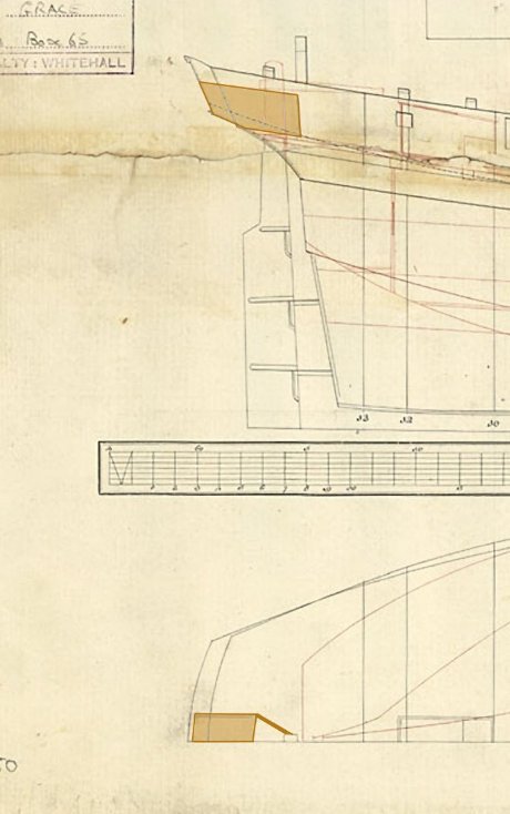
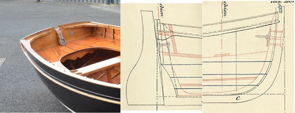
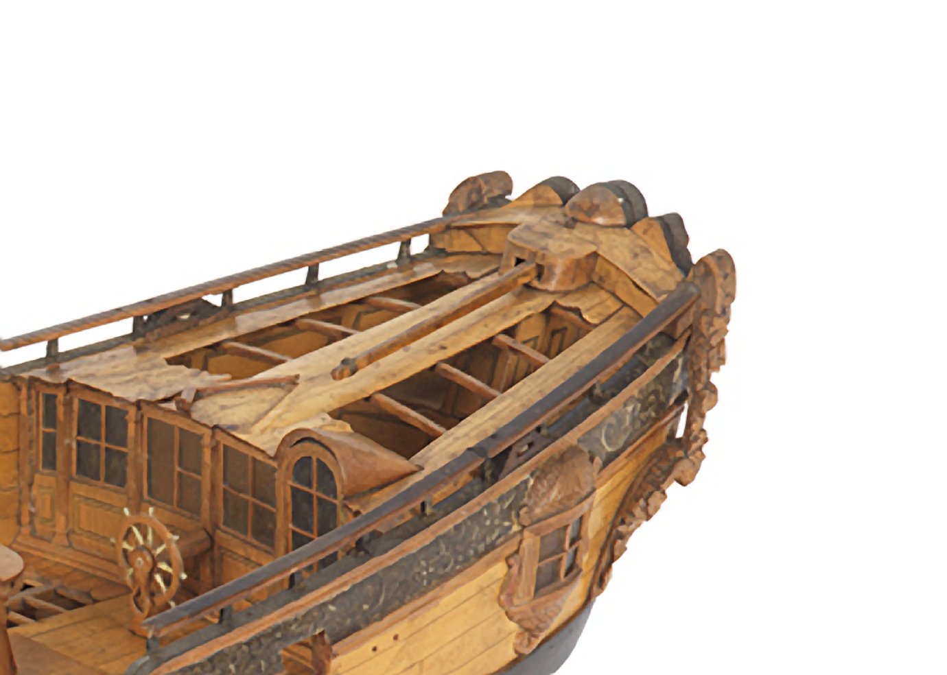
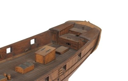
I did understand what you wanted but I don't think you are going to find anything. I hope somebody will prove me wrong. In all the cutter plans I have, the structure on the Grace is unique. The Watchfull (ZAZ6466) and the Starling (ZAZ6479) have rectangular structures doing the same job but these are only shown on the deck plans so there is no height information. The two models below have structures doing the same job but are very different.
-
Cutter Grace 1763
iMustBeCrazy replied to tabycz's topic in CAD and 3D Modelling/Drafting Plans with Software
Something like this maybe?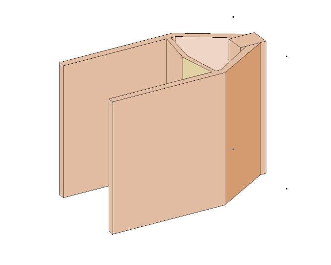
-
Cutter Grace 1763
iMustBeCrazy replied to tabycz's topic in CAD and 3D Modelling/Drafting Plans with Software
I would assume that's it's primary purpose, but it seems overly large. If it was my ship that extra space would be used for something even if only for storing buckets.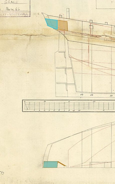
-
Cutter Grace 1763
iMustBeCrazy replied to tabycz's topic in CAD and 3D Modelling/Drafting Plans with Software
My guess is a wooden enclosure, covered aft of the rudder. Probably used for storage simply because it could be.