


stuglo
-
Posts
701 -
Joined
-
Last visited
Content Type
Profiles
Forums
Gallery
Events
Posts posted by stuglo
-
-
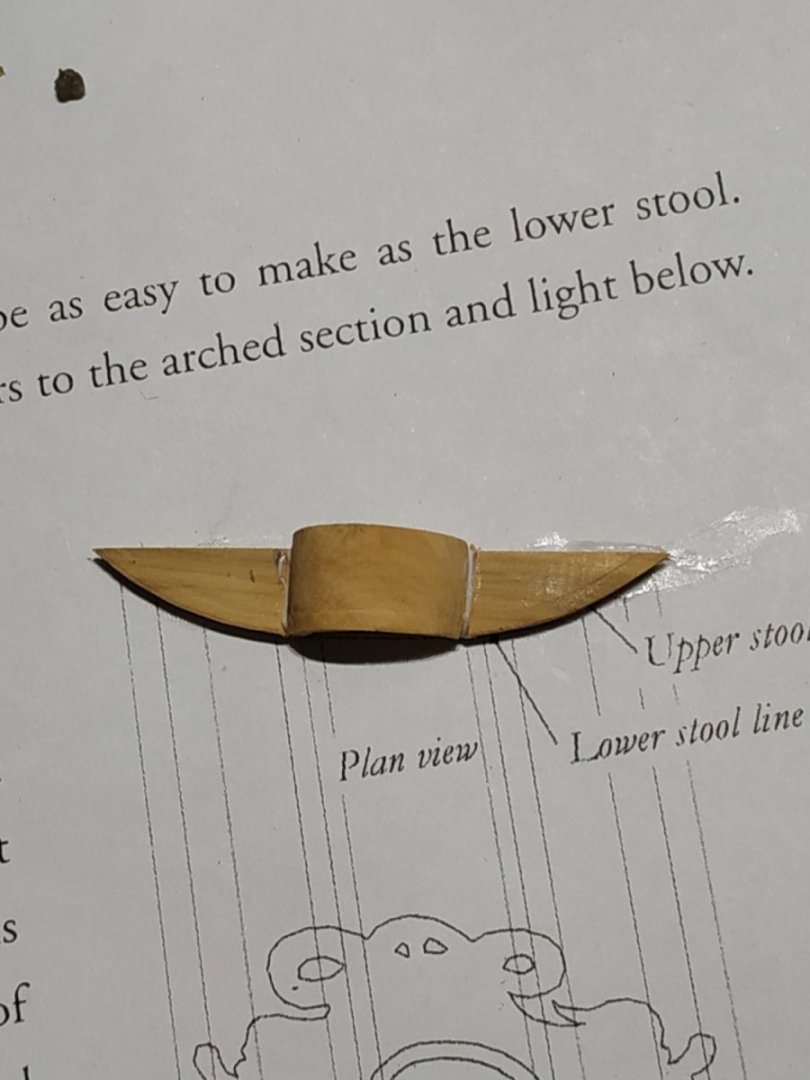
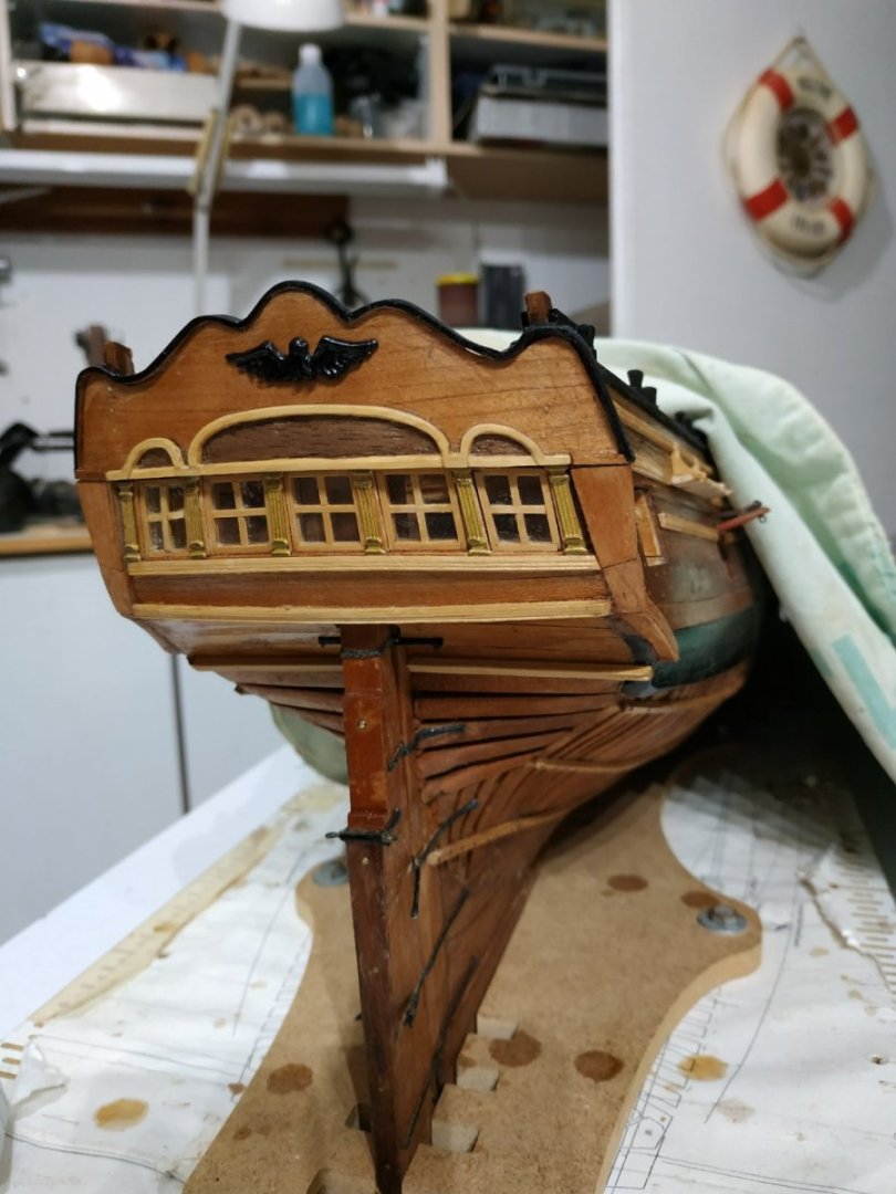
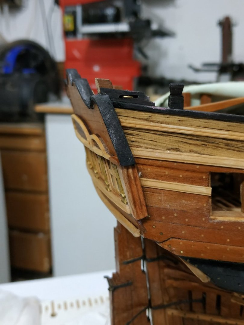
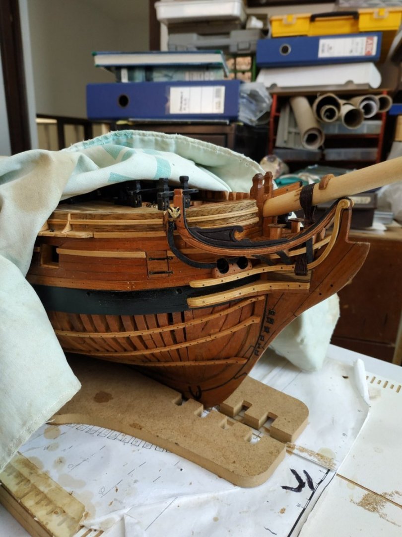
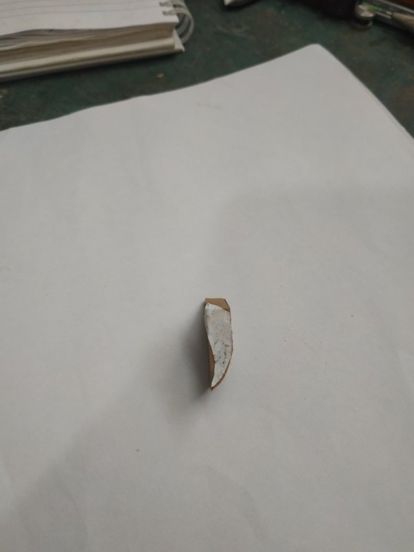
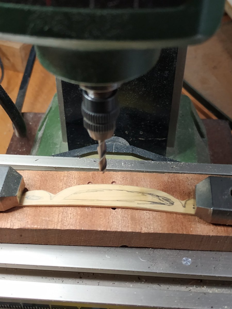
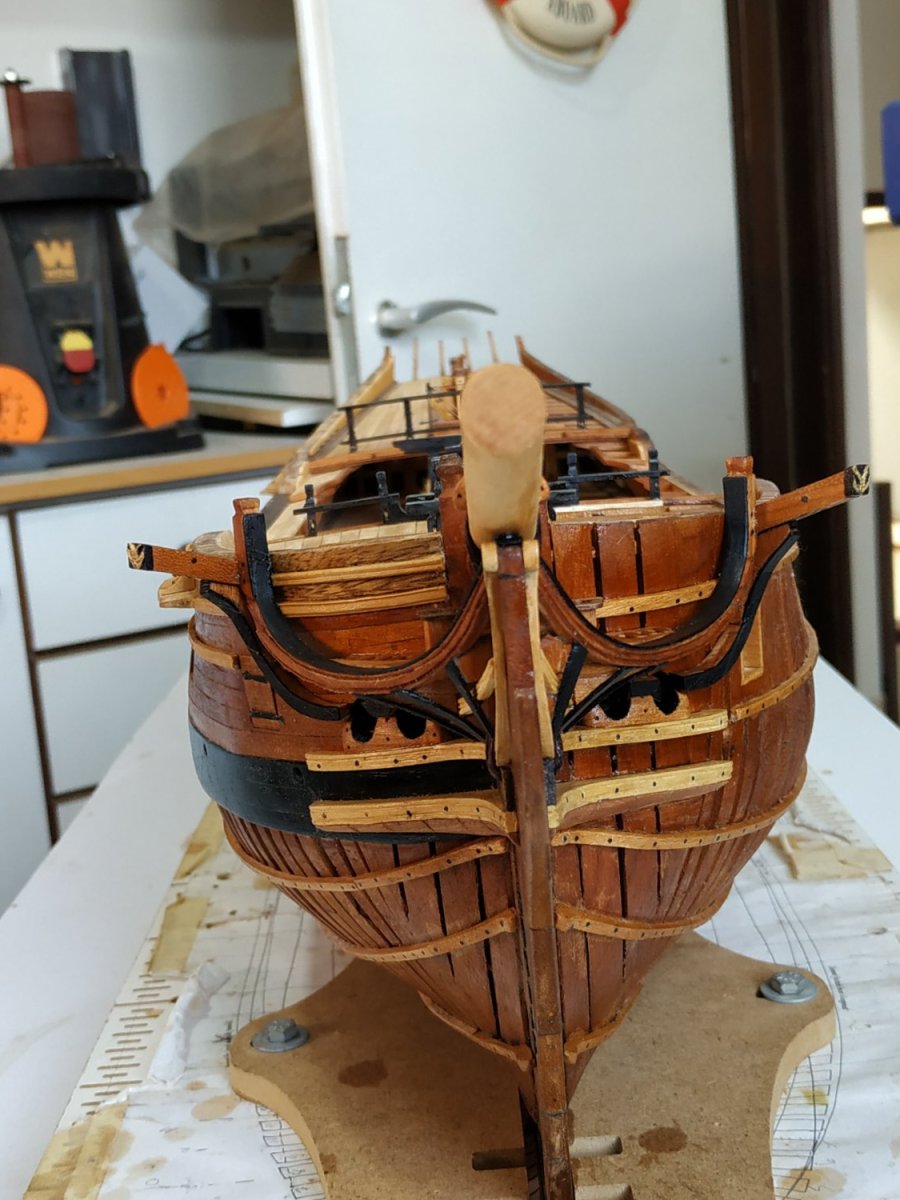
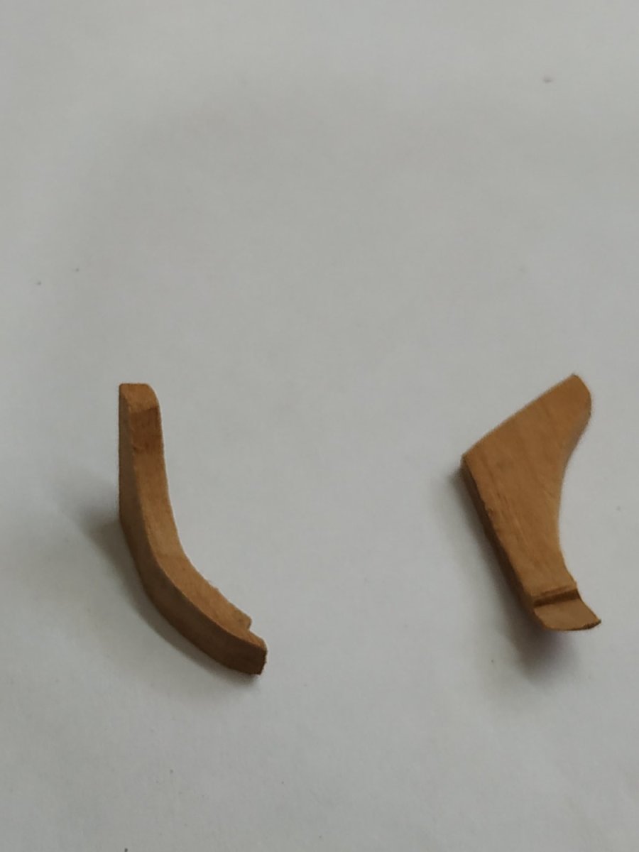
The Quarter Badge
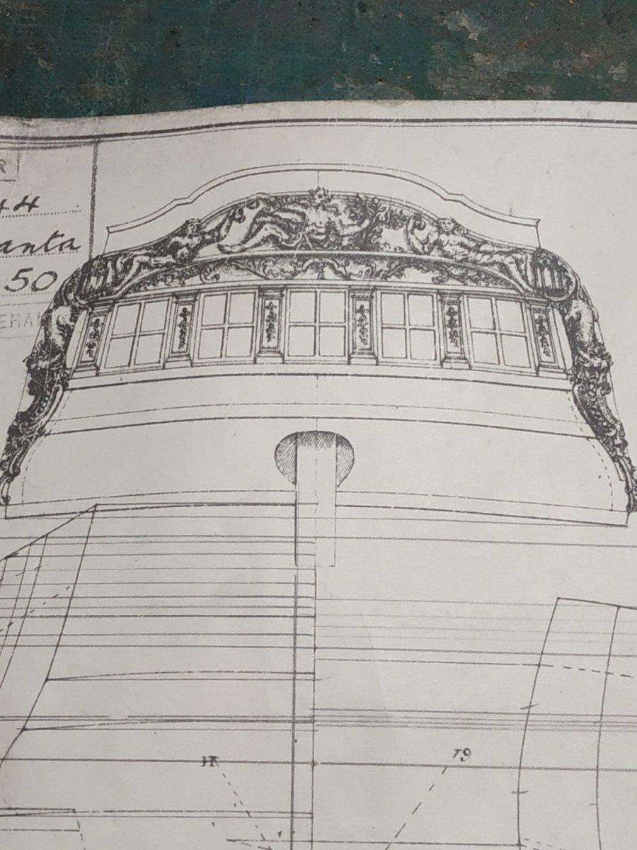
Instead of the Gallery in biggerships. Will refer to Atalanta plans for basic outlines, but without the fancy stuff. Apparently, this fitting was very varied.
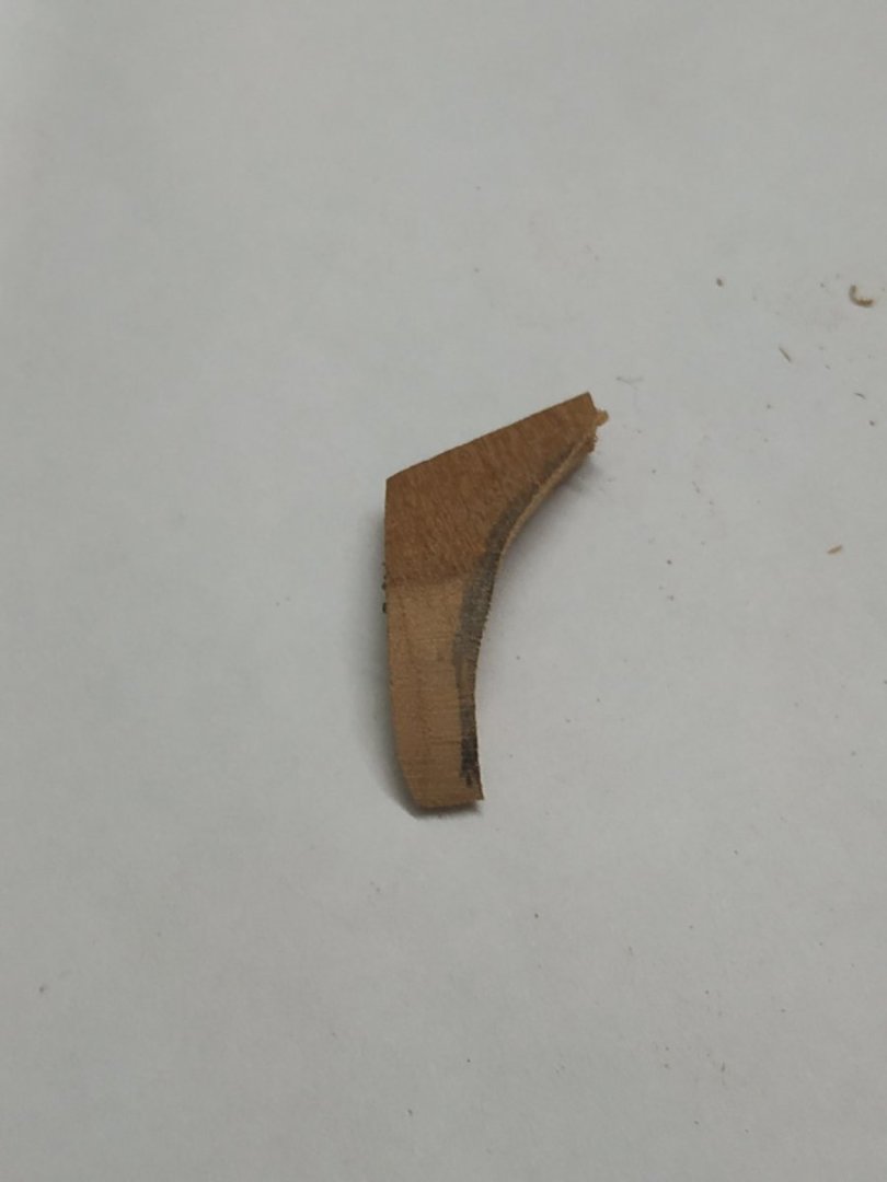
The critical parts are the Upper and Lower Stools. The inboard side is attached to the ships side and follow these rules :They are parallel to each other
They project no further out from the ship than the Quarter Pieces
Outboard shape is elliptical
Athwartship, the upper surface is horizontal
Molding on the outer edge (3D shows the difference between Upper and Lower)
Upper Stool is slightly smaller.
Lower Stool.
Check height and slope to plans.(the slope parallels the slope of the Sheer Rail in my plans)
My finished width is to be 6.8mm, thickness 2.2mm and length 46
I made the molding off the ship using a scraper scraper, and then reduced width and fitted the inboard surface to the hull with PVA and a couple of drops of cyano to grip while drying.(Pinning seemed a bit dodgy.)
Upper Stool
Very slightly smaller than the Lower Stool.
Made a different molding as this (seemed) to be shown on the 3D
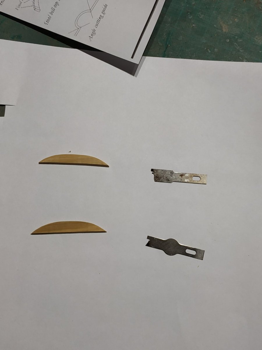
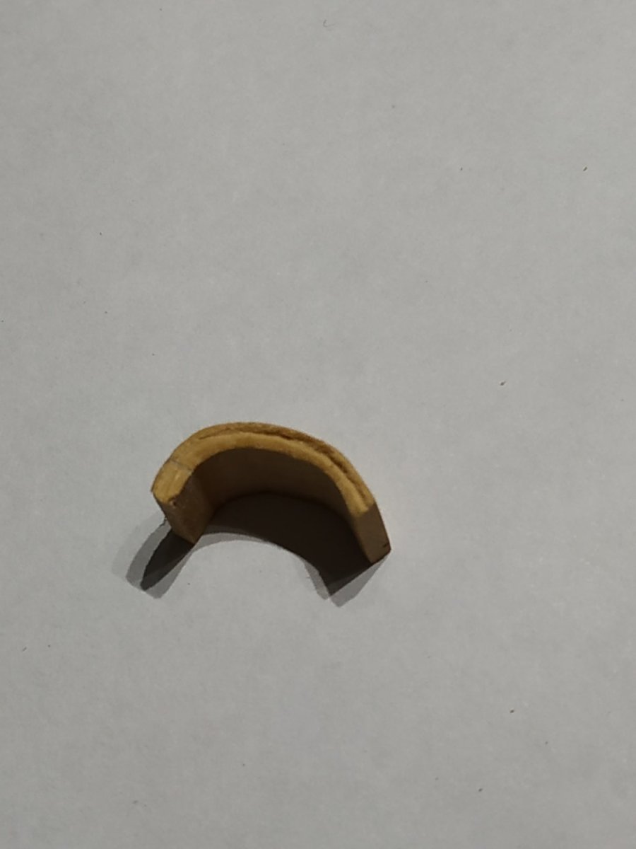
The approx, middle ⅓ is replaced by the Bell-top, a sharply arched structure, with the thickness and molding of its “wings”,
The shape is described as an “irregular skewed ellipse”. ?Because of the slope, a regular ellipse looks odd.
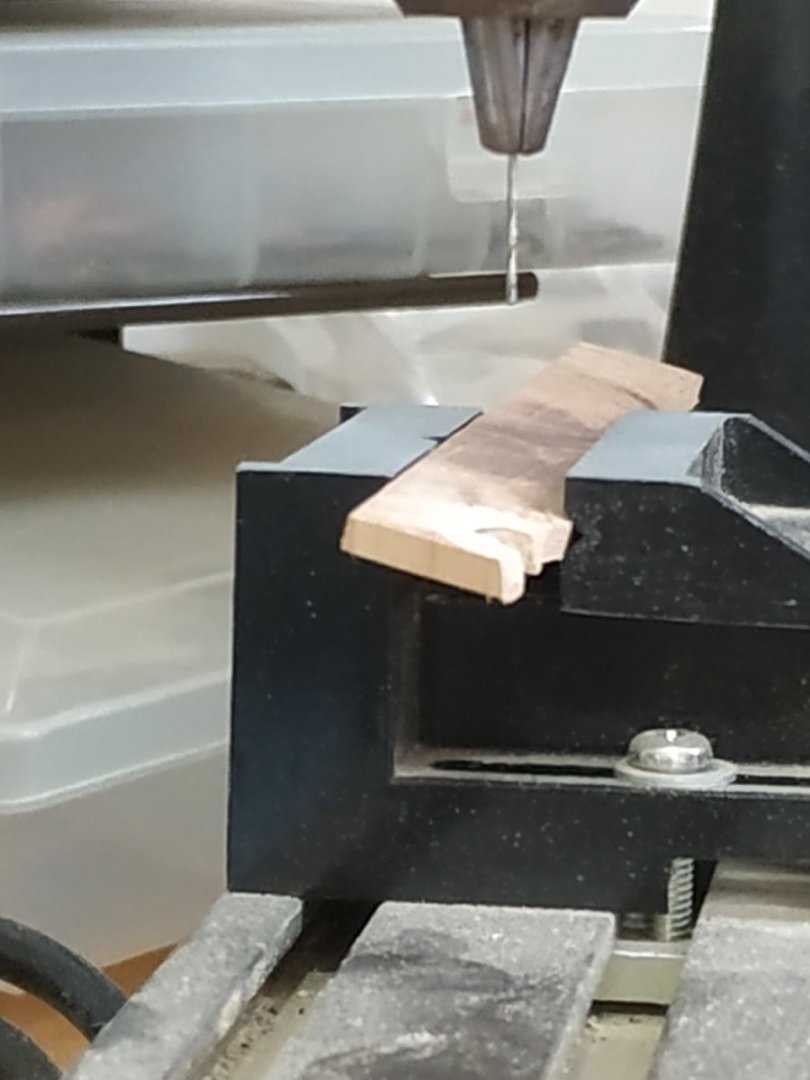
Using the pattern from TFFM and a blank 10x8x9mm milled and filed the shape, including the minimal curving of the outer edge and the 45deg joints. **The corners broke with scraping the molding.**
Again using the plans, removed the middle segment and the edges sanded to 45deg so that the Bell-top fitted with the make the appropriate total length for the Upper Stool.
After gluing, the molding can be patched up where the corners were reattached.
I used boxwood for colour and relative ease of scraping the molding, but on the curve this was difficult. The asymmetrical shape was not the easiest to make. Thankfully, only putting on one side.
Note also when gluing the Bell-top to its wings, ensure alignment horizontally, and between their inboard surfaces. When glued, the surplus from the inboard surface of the Bell-top can be removed and the whole beveled to fit to the ship’s side so the upper surface is horizontal.
Ensuring the Bell-top sits over the port, the Upper Stool is parallel to the Lower Stool and starts about 3mm aft of it. Glue in position as before.
Go away and rest until the glue is firmly set before any more messing !!!.


- Prowler901, Trussben, Dave_E and 4 others
-
 7
7
-
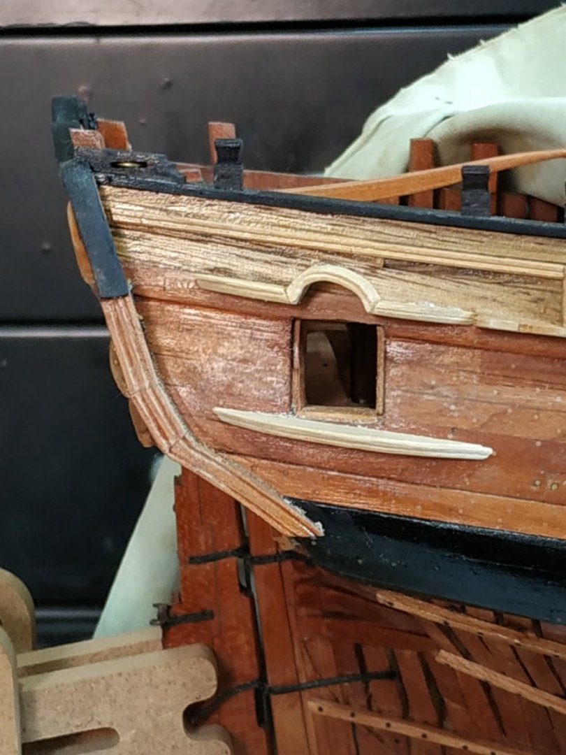
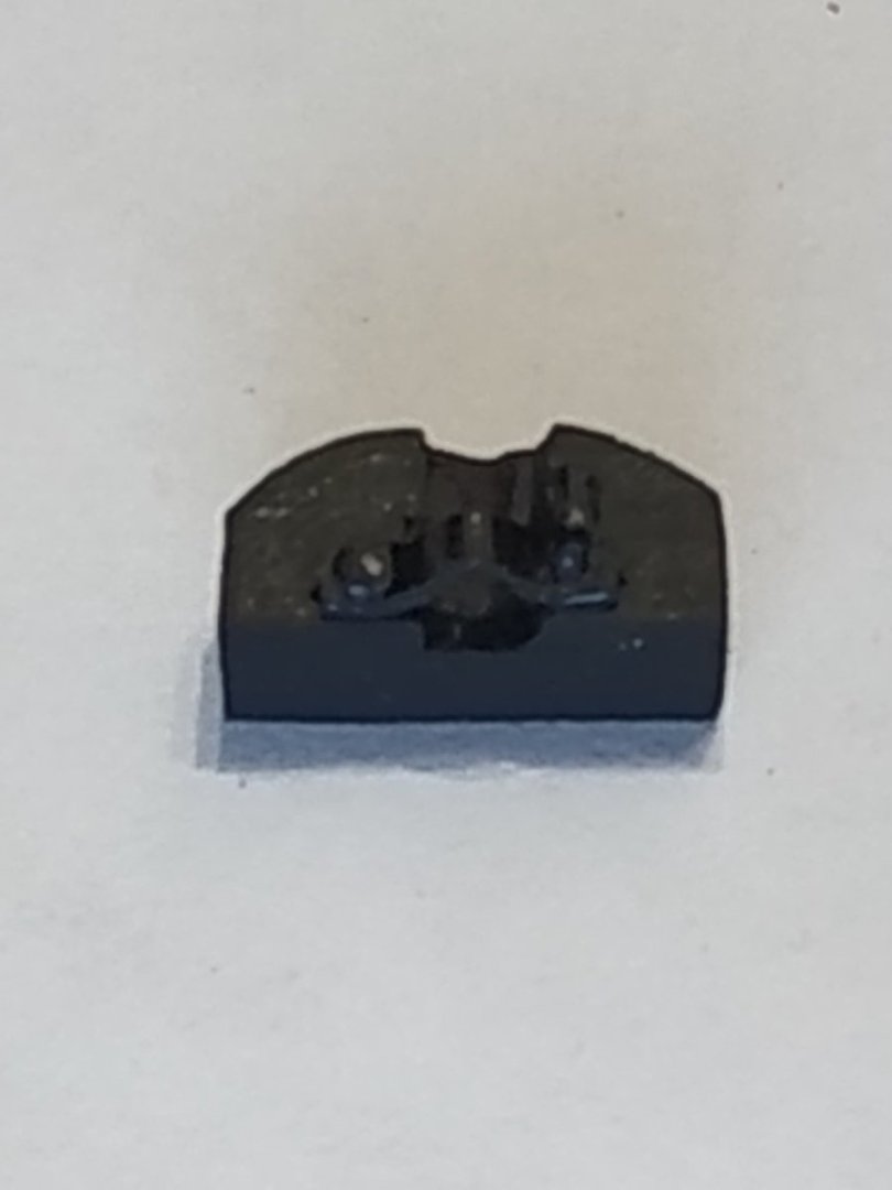
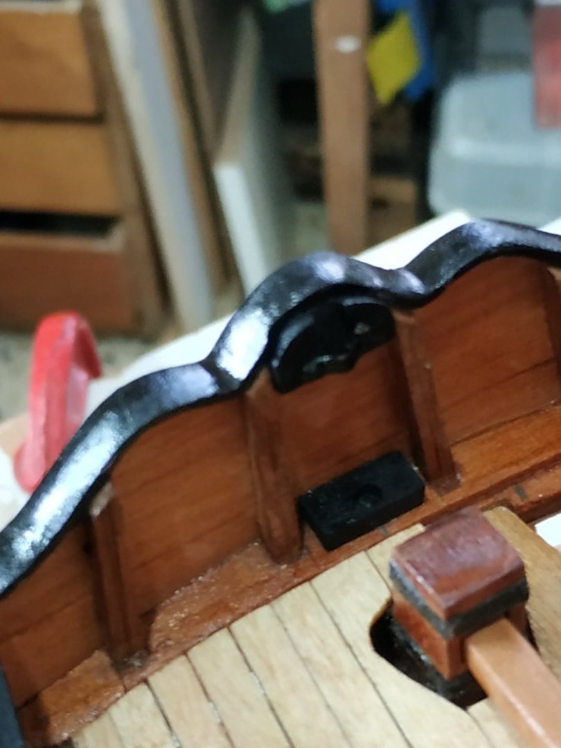
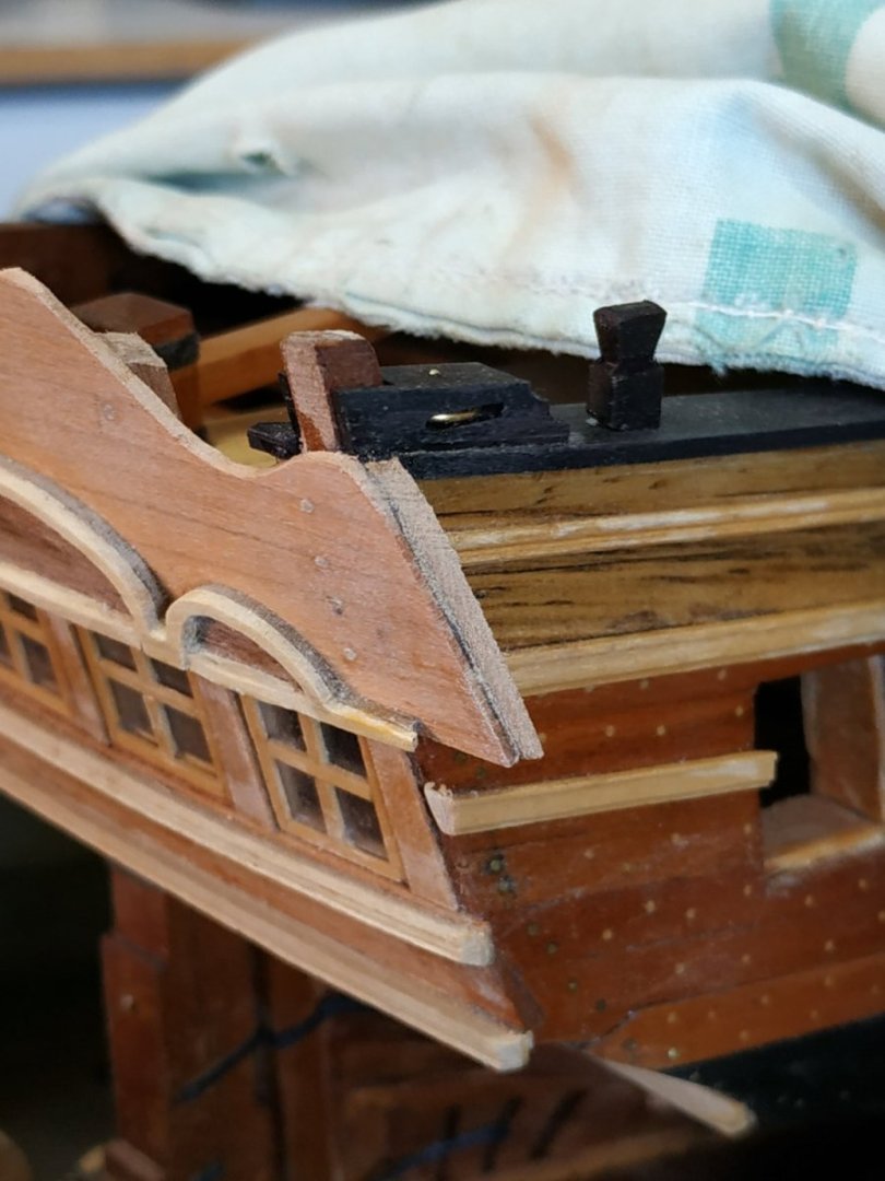
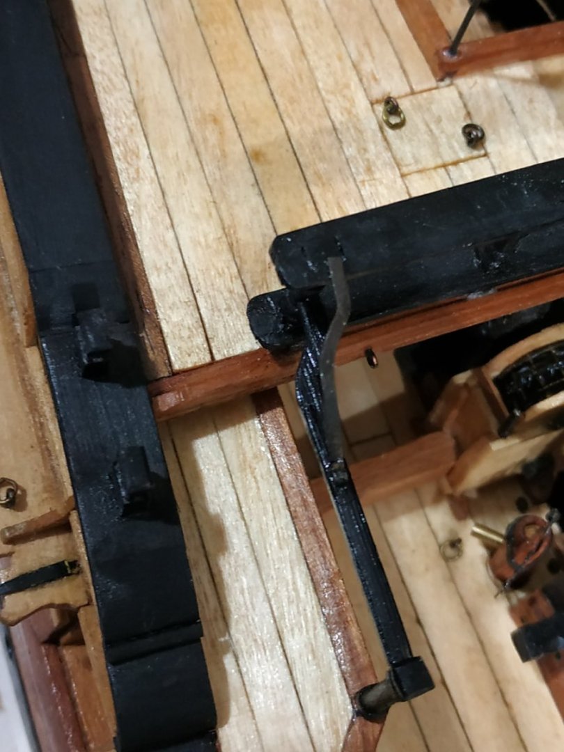
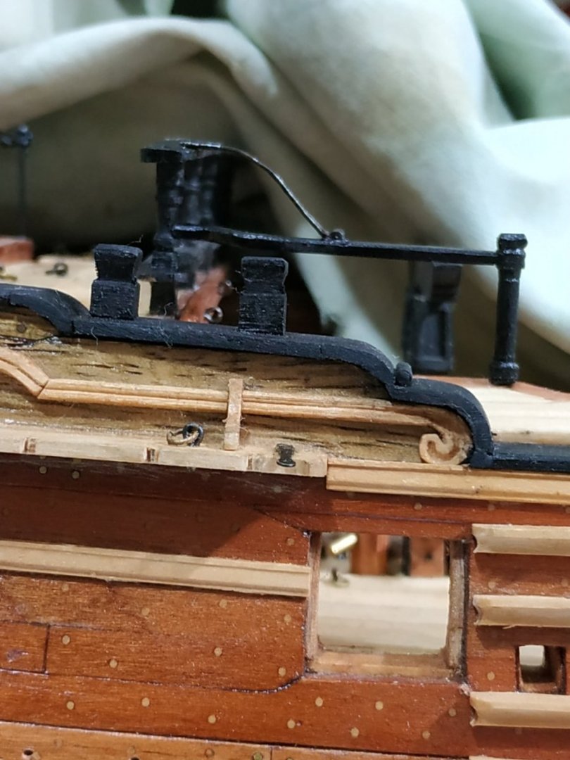
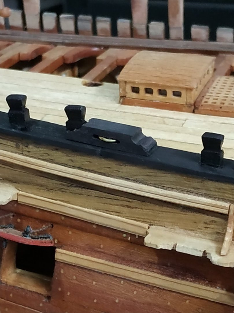
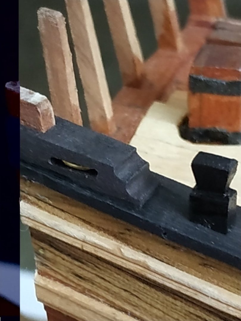
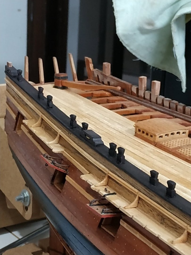
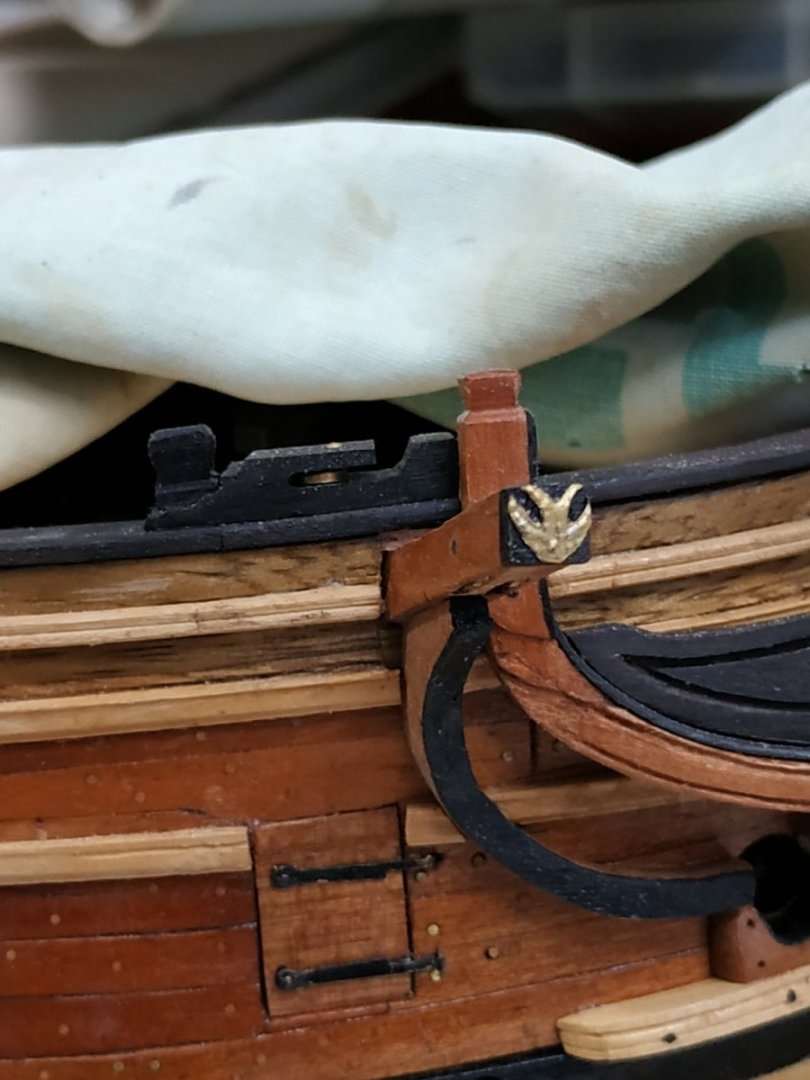
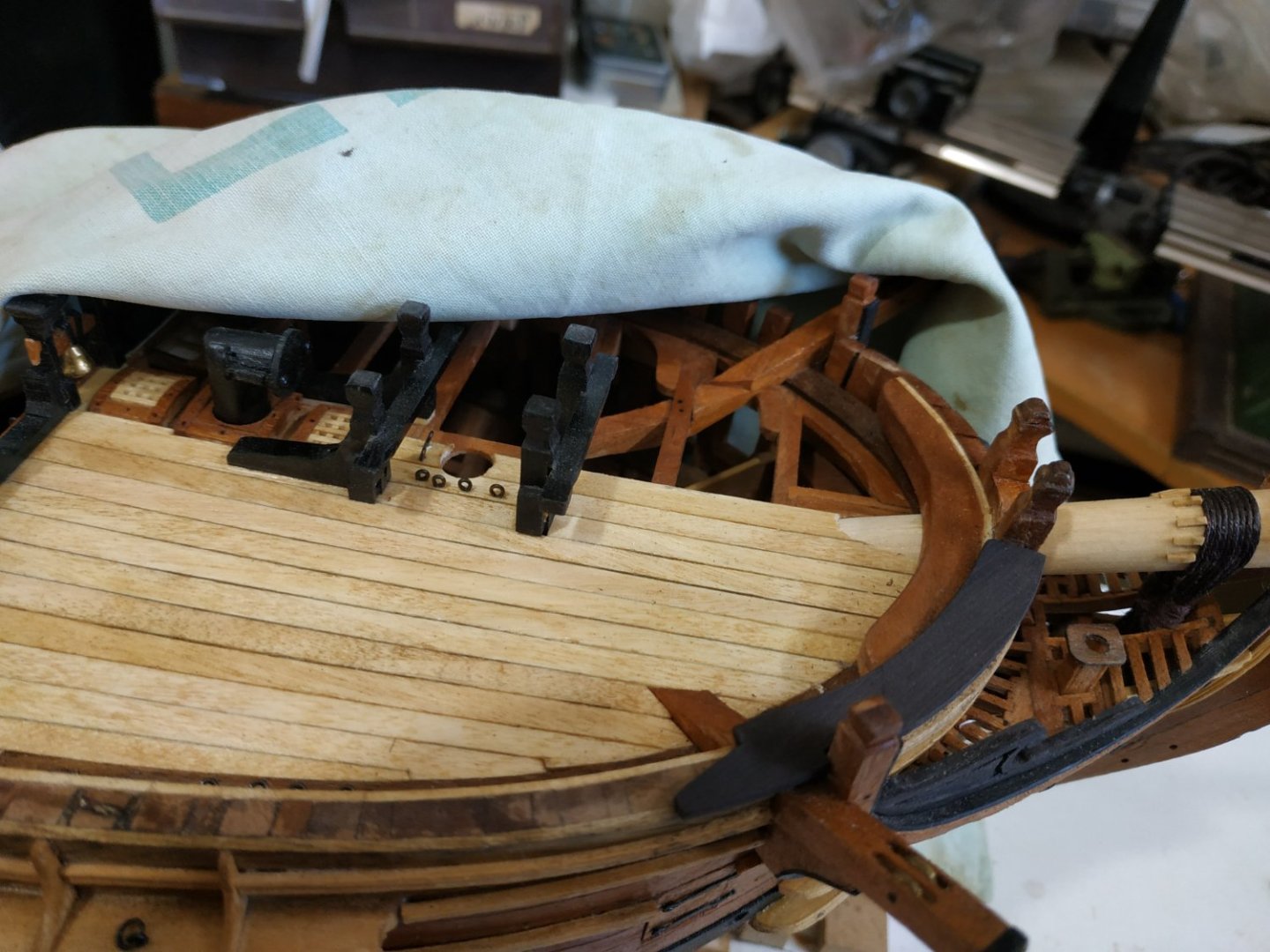
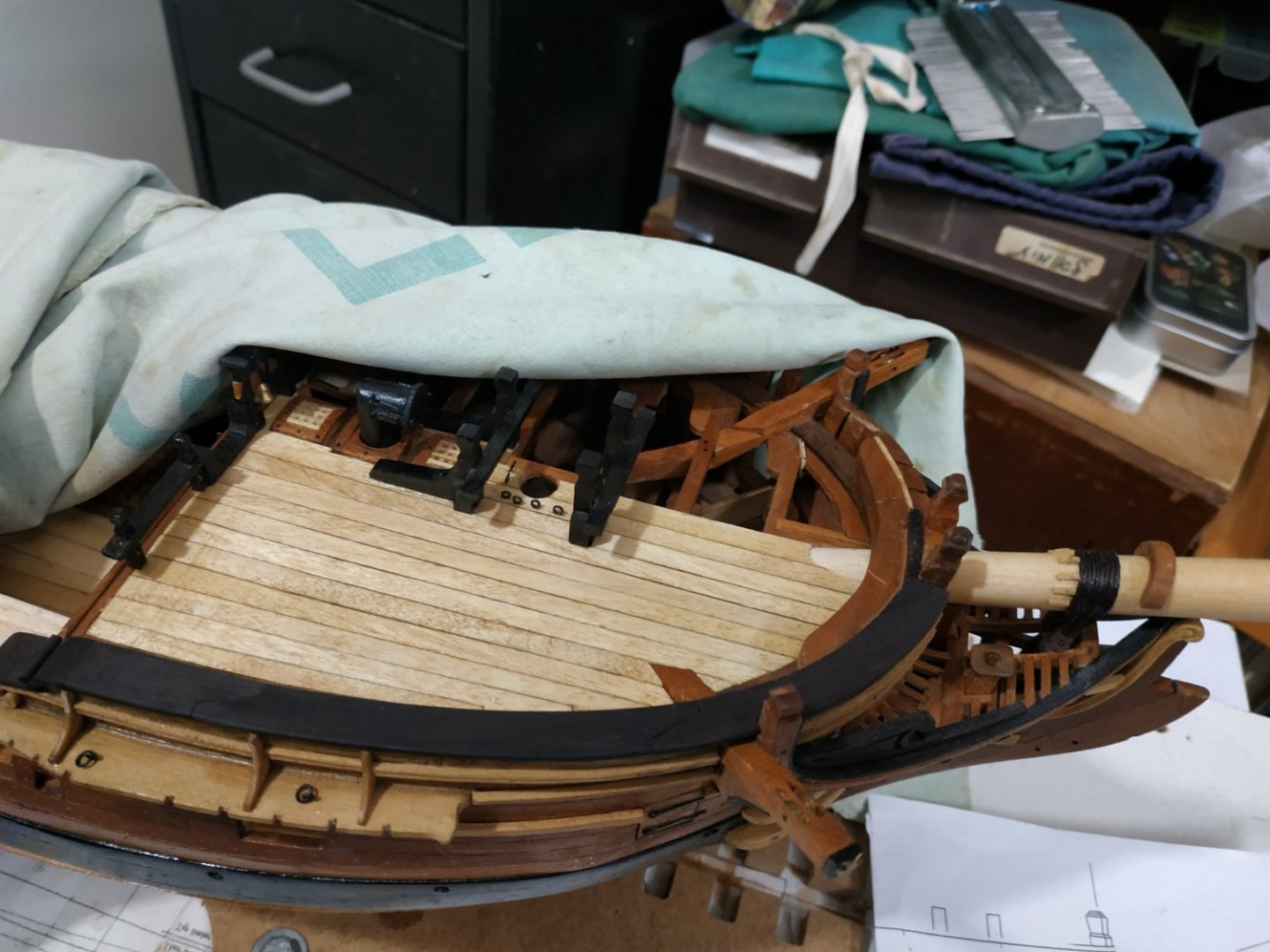
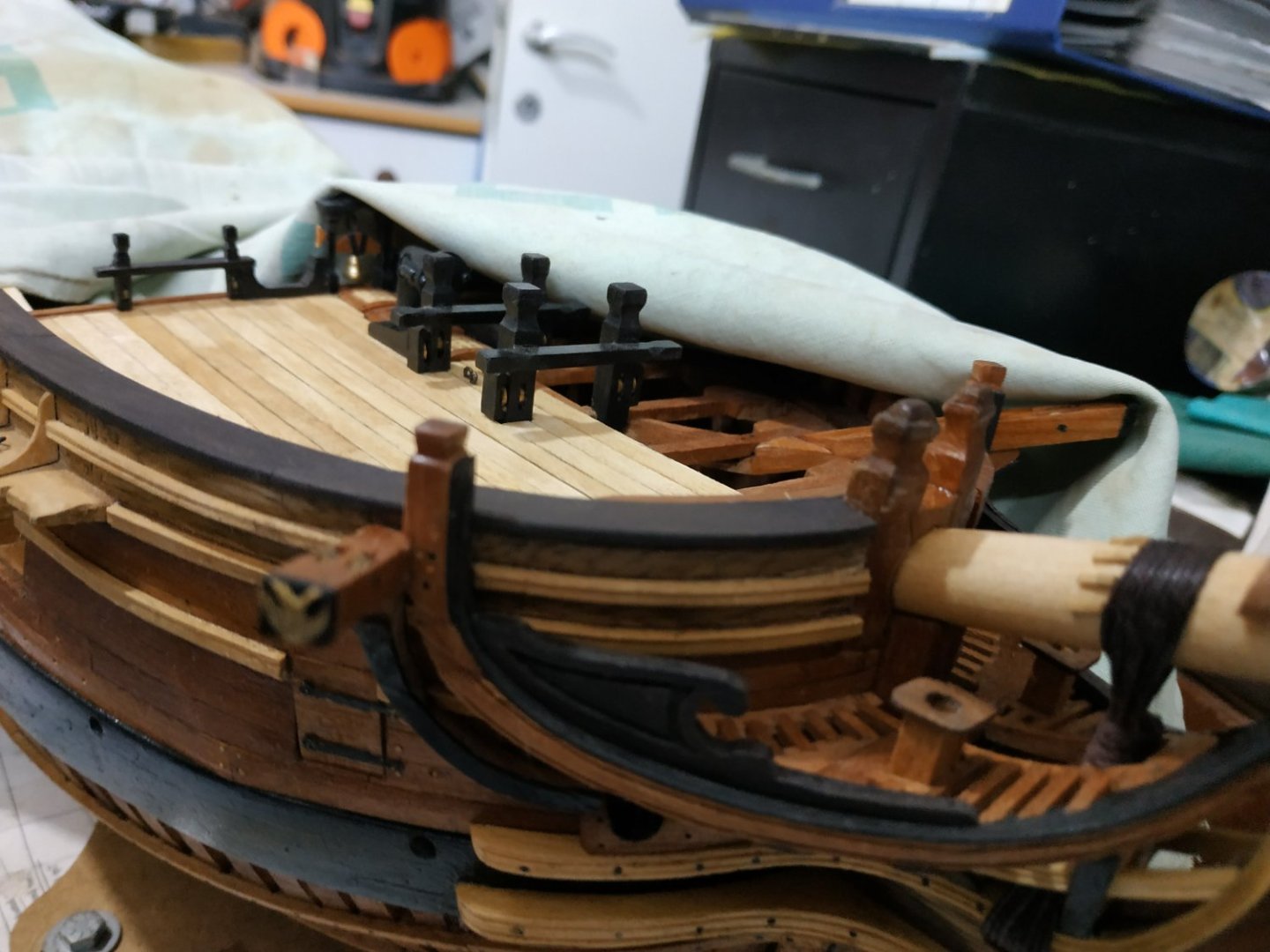
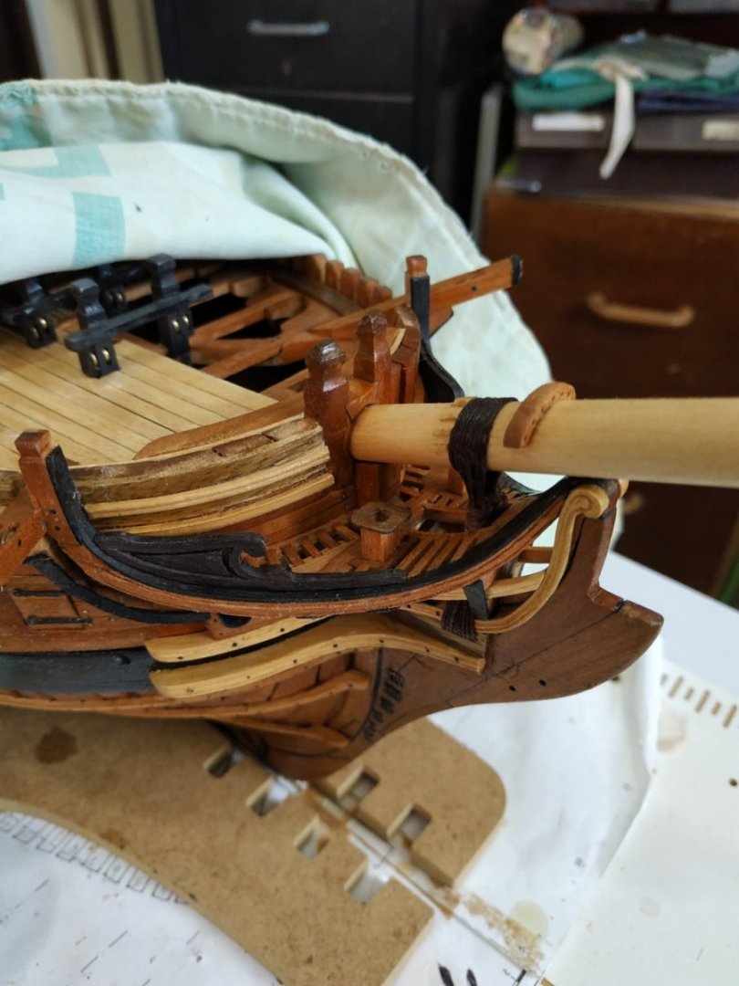
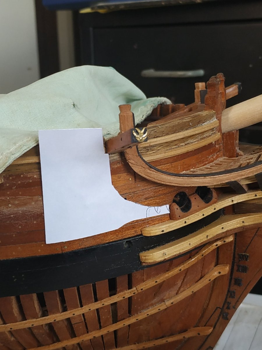
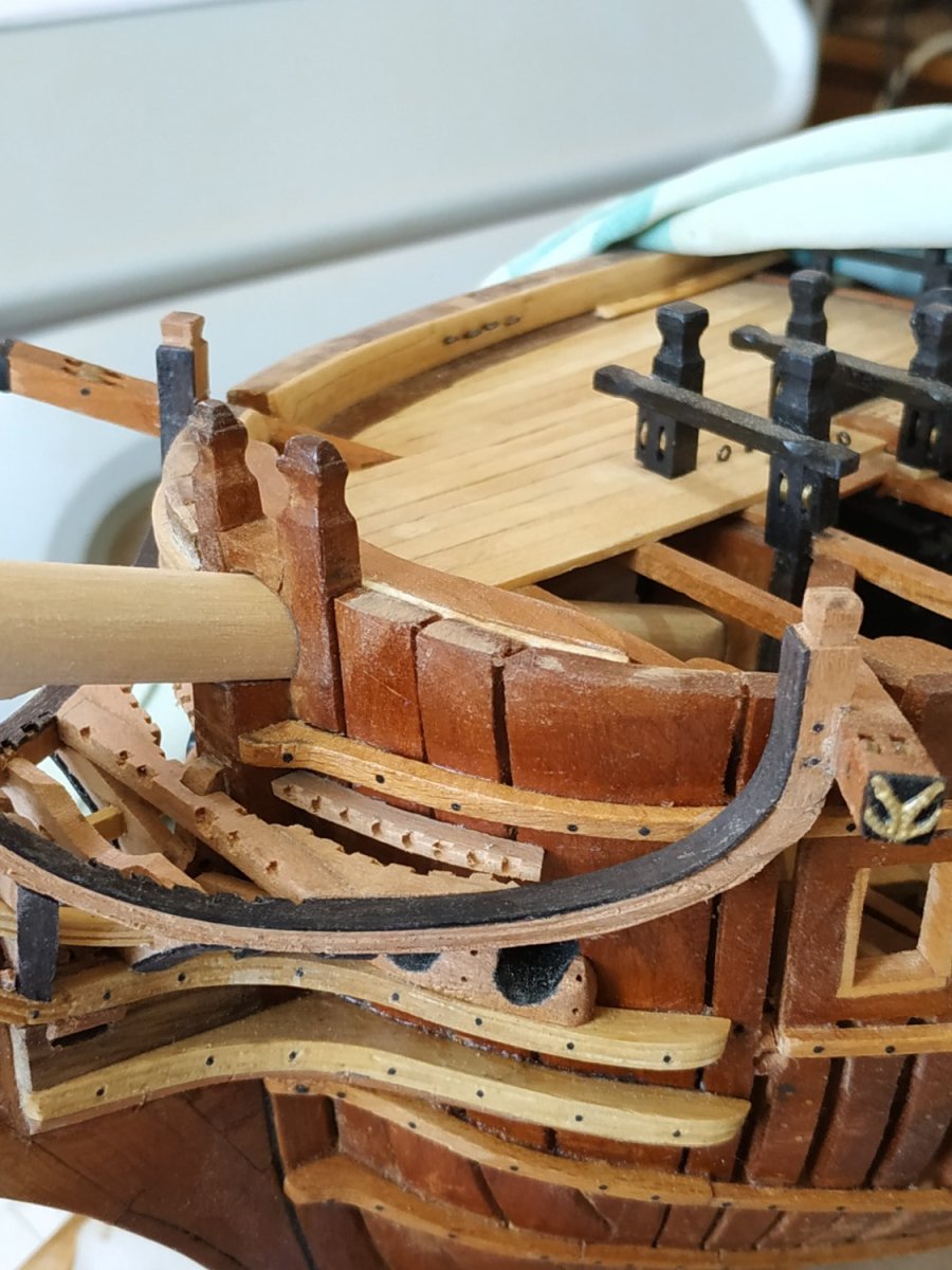
Ensign Staff Capsquare and Step
This is shown as a horizontal piece inserted into the Capping Rail, to support the Staff.
However, due to the dome-shape of the central area, I followed that shape for the upper surface.
The staff has a diameter of 2.4 mm, so a vertical groove was filed out at half this depth.
The Capsquare is similar to those on the cannon trucks, so I used one, brass pins, one bent over to represent the bolt.
The step is a simple rectangle with a 2.4mm hole, and fixed to the deck.
- dvm27, KARAVOKIRIS, Prowler901 and 8 others
-
11
-
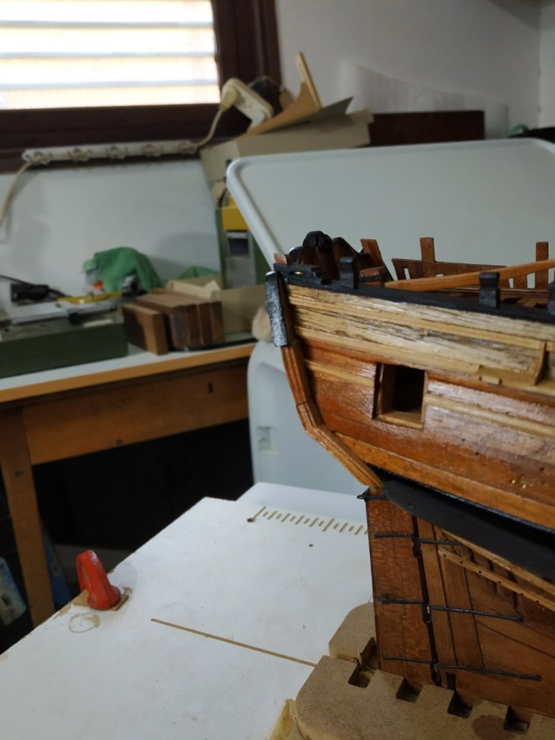
Lower Quarter Pieces.
Continuing downward from the Upper Quarter Piece, it extends to cover the upper Wale strake.
Follows the curves of the Stern and the Hull, thinning downwards- more so across the outer face. Molding with shaped scraper.
Not satisfied with the first attempt. I didn’t consider the effect of the grain and different wood shade.
Remade both the Upper and Lower Quarter Pieces
The bird of prey is homage to the build log of Dan Vadas’s HMS Vulture. This helped me over some significant difficulties. A great model ship builder.

- Knocklouder, ccoyle, CiscoH and 4 others
-
7
-
-
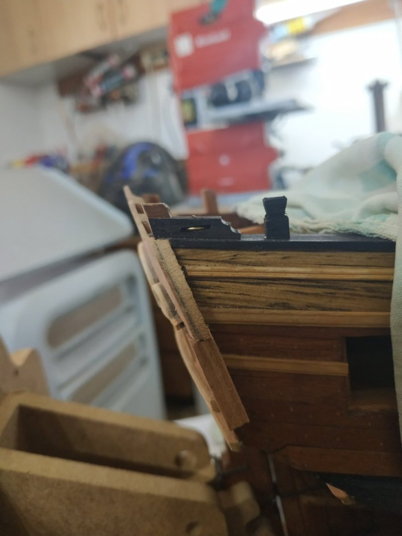
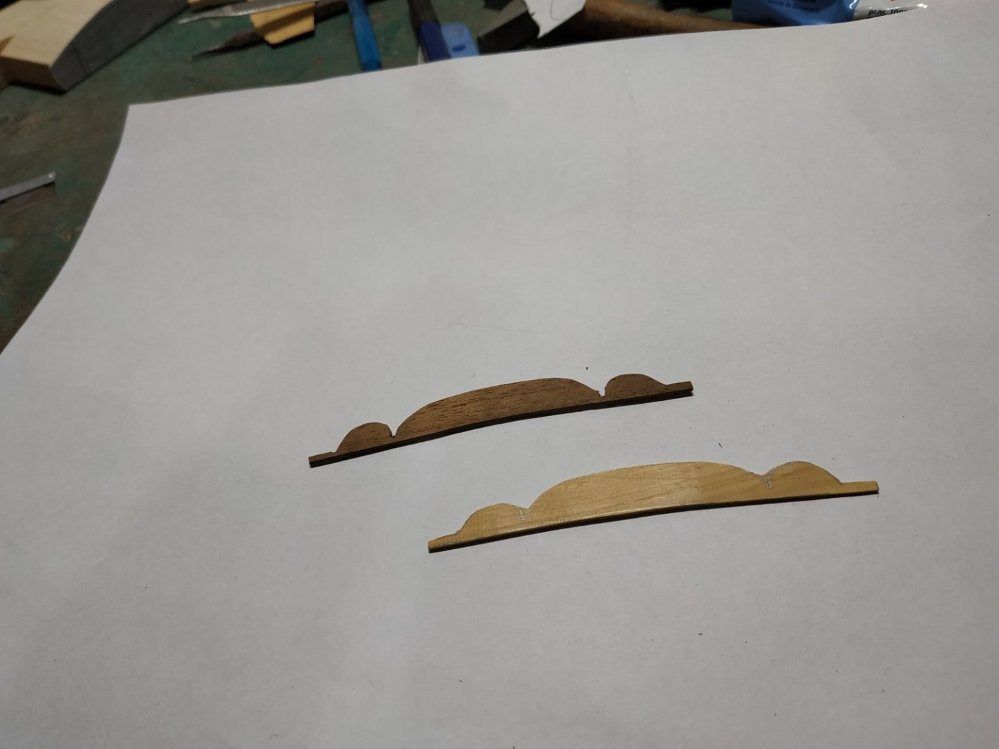
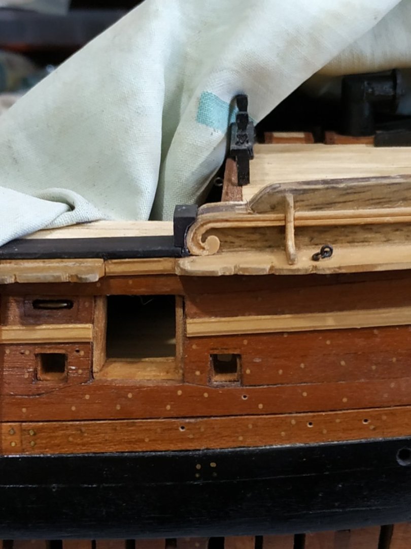
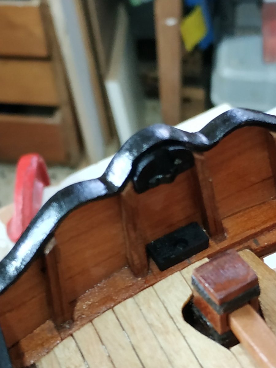
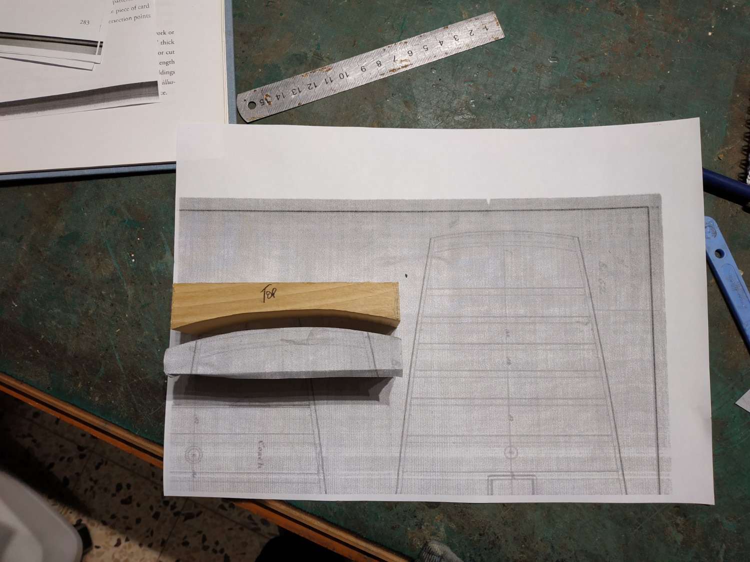
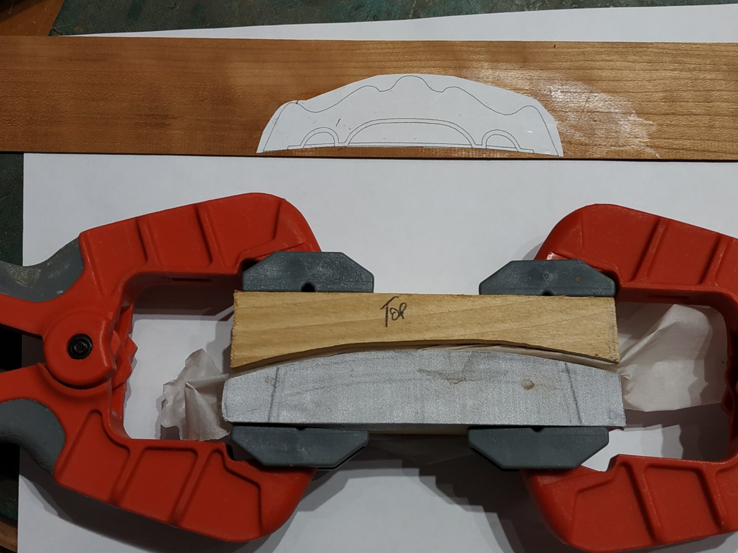
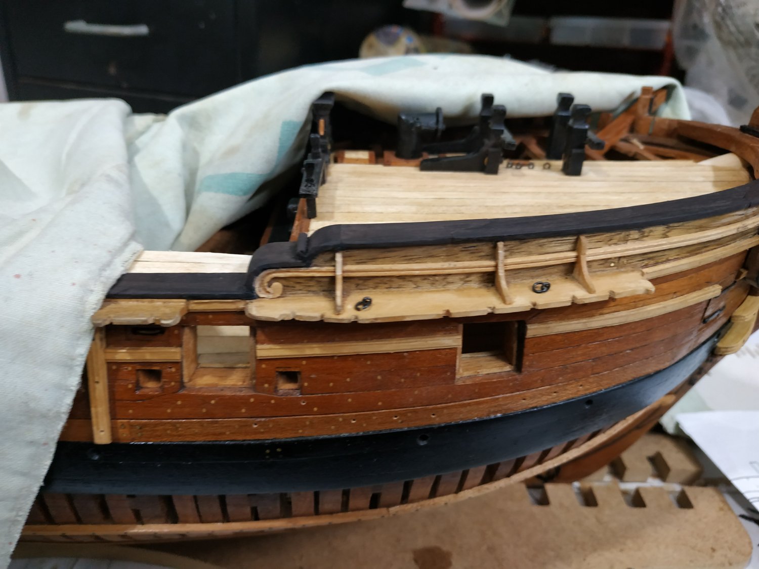
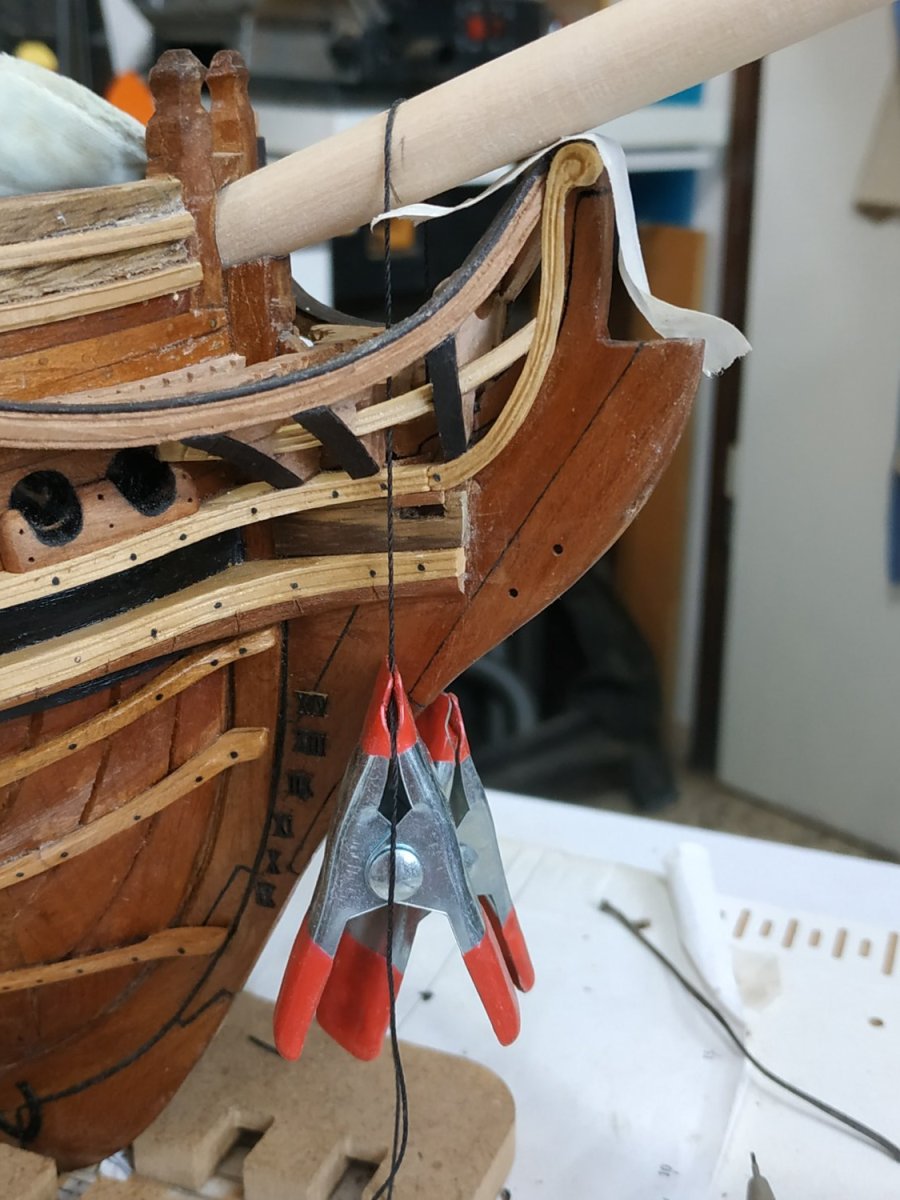
Capping Rail
A narrow molding above the Taffarel.
4.5mm wide and only 0.8mm thick.
I made it thicker as my first attempt broke and to ease my conscience, thickened it to match the plansheers.
I considered various methods - several short sections or bending (? possible in 2 planes without twisting) and decided to make it in 3 pieces, the main from bulwark to bulwark, and shape it from a solid blank, 11x18x15 CMS.
Firstly, the curve of the Stern, then roughed-out the shape of the upper Taffarel. Sanding and file to shape, then thin to the decided thickness. The outer parts are easier.
Before fitting the middle section, file out a section in the centre where the Ensign Capsquare Base will fit (12.5x1.3mm).
(I followed the TFFM pattern for the Taffarel, but there is much variation. Below is the plan of the Atalanta- the form of the Caprail would be relatively easy, but all that carving!!!!!)


-
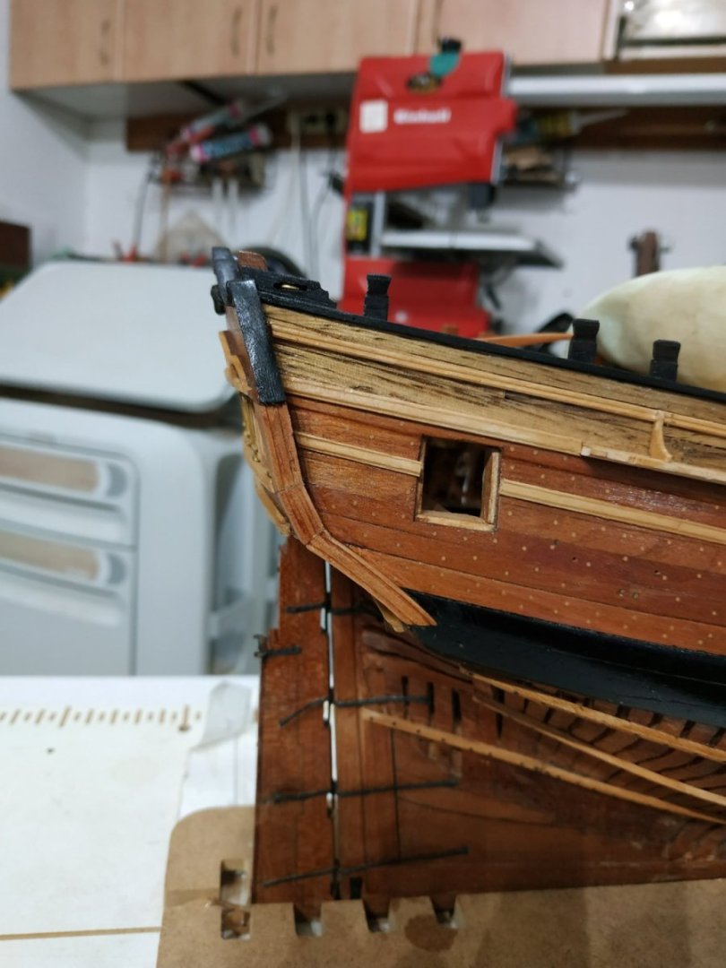
Upper Quarter Piece
A piece, outboard and level with the Lights, extending downwards of the Additional Thickness Piece.
Width and thickness of said Piece, narrowing downwards to about 5.5mm.
My outer surface has a molding rather than some fancy carving- some sources say this was a possibility.
- Knocklouder, No Idea, KARAVOKIRIS and 1 other
-
4
-
Structures of the Stern.
I’m somewhat daunted by this. Its a visible structure that seems complicated to make.
As usual, TFFM simplifies this into a number of steps.
Taffarel Pattern.
Explanation given how to draw this given the ship's plan.
However the final result pretty much suited my build, so I used this directly.
(I have plans for Atalanta and the Fly -the size and pattern of the Stern are different.)
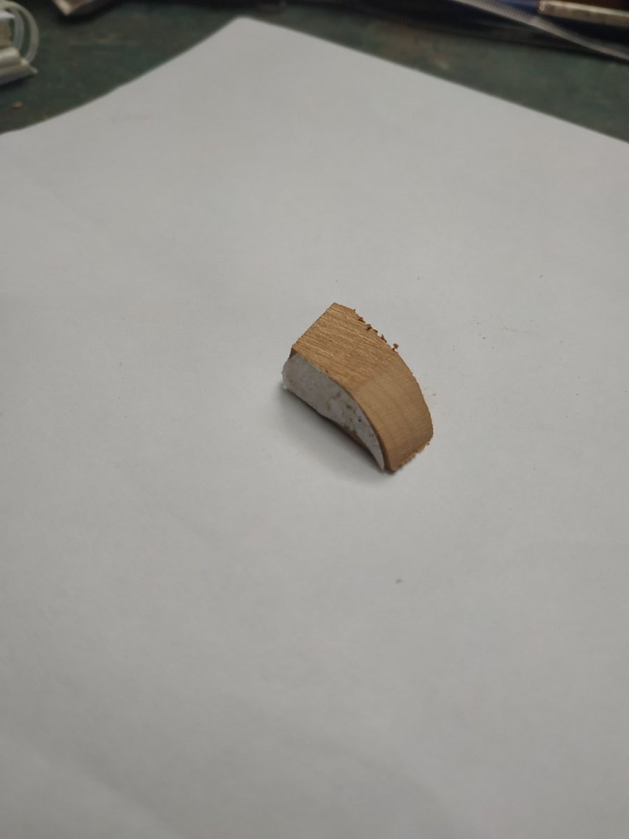
Taffarel Base.
In order to shape the curve of the Stern, a jig was made. A spare block of wood is split into 2 halves, using the shape of the curve taken from my Atalanta Quarter Deck Plan.
The formed Stern will be clamped between the 2 halves.
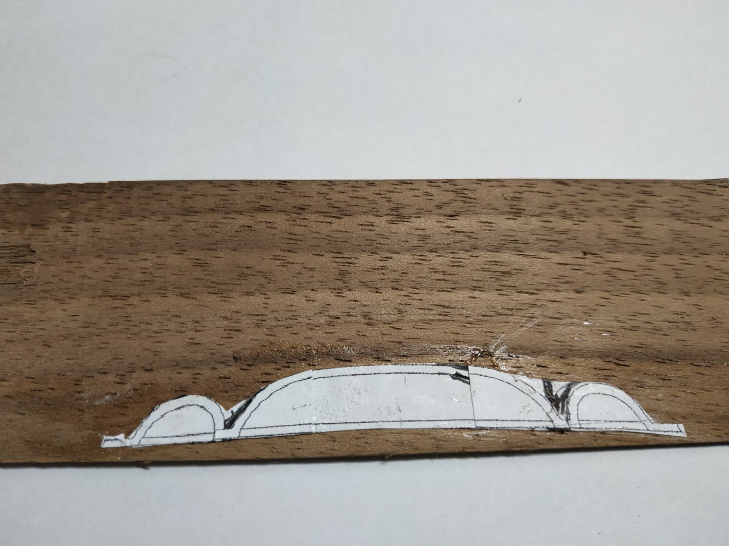
The Taffarel.
TFFM describes a thickness of 3.18 mm below the line of the Coves - 1.06 mm above.
Within the Coves, the area is carved out into various decorations. To avoid the carving and thinning I followed the suggestions of Dan Vardas’s blog.
Using 3 pieces of different woods, I made each the same thickness of 1.03mm.
The outer and middle from the same pattern - just the area of the Coves and Necking..
Some small alteration was necessary to match the Arches of the Coves to the position of the Munions.
The shape of the Coves marked and the “rim” roughly hollowed out with the mill.
These 2 are glued and clamped in the jig.
Using the full pattern, and the inner layer was cut out.
(**When offered to the stern I found it fell too short of the Quarter Deck Planksheer-and I had to remake it.**)
The outer pair is now glued to the inner layer and pressed within the Base jig to try with the required curve. ( 2 spare bits can be used to even out the sandwich.)
When dry, using the convex side of the jig to support the part, the Coves, the Arches and Necking are further shaped with scalpel and chisel.
The whole is glued and pinned with treenails to the Countertimbers.
Additional Thickness Piece.
Forward of the Taffarel extension beyond the Hull, 2.12 mm to match the thickness of the Quarter Pieces.


- French Mr Bean, Prowler901, Matt D and 7 others
-
10
-
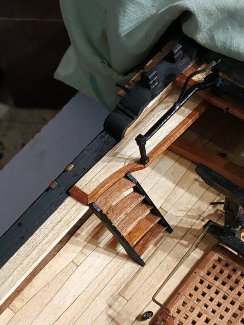
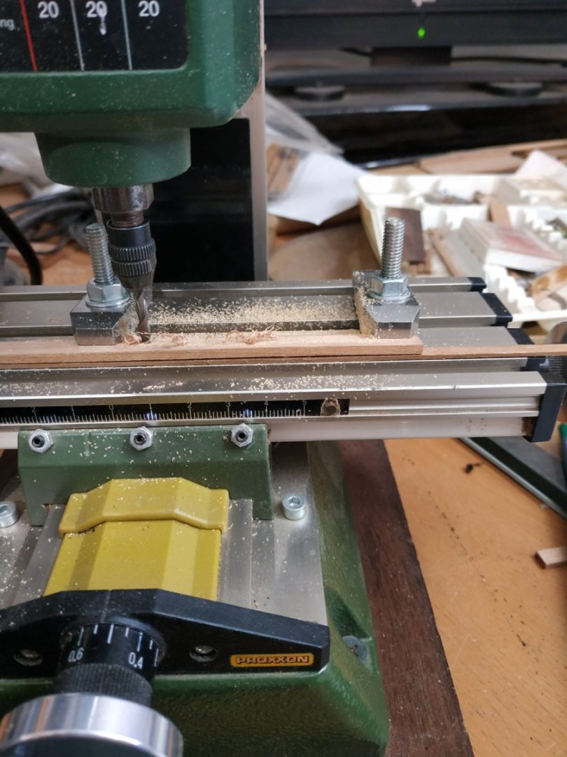
Steps to the Waist.
From the Fixed Gangway to the Waist of the ship.
Styles 1.33mm thick, steps 0.8mm thick
To position the Styles that follow the curve of the Gangway, then are in line on the deck, the upper steps form a curved or “winding” shape.
***********************************************************************************************************
Rather than set up the table saw, sledge and jig to groove the styles, I tried my trusty mill.
The angle of the styles to the deck was about 60. Geometry 101 gave style/gangway about 30.
The 2 sides of the styles must have opposite grooves.
I cut a piece of a point of 60 to some thin spare stocks, set it vertically, then clamped the styles either side of this and ran the mill piece horizontally across both. Repeated passes at 6mm intervals, and voila, matching grooves for the styles.
- Dave_E, Prowler901, mtaylor and 3 others
-
6
-
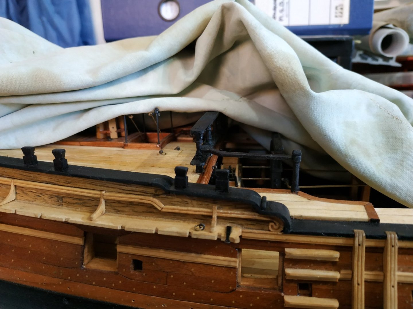
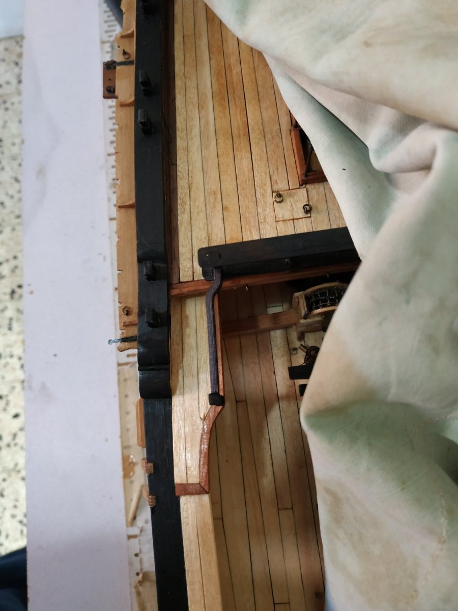
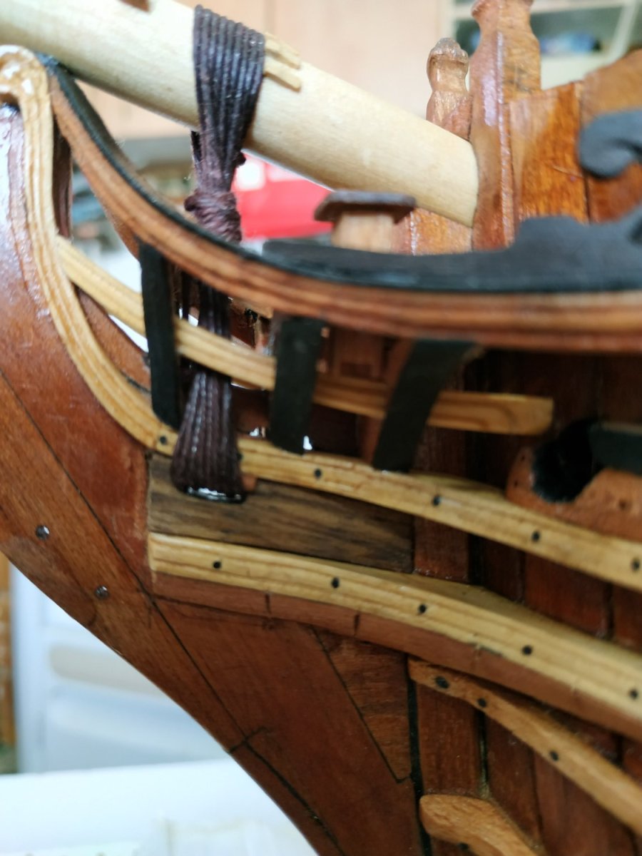
Fixed Gangway Newel Post and Railing
The Post:
From the corner of the Fixed Gangway, supporting the Rail which runs to the outer Stantion of the Quarterdeck Breastwork. .
The Post is 22.3mm high and made from 2.65mm sq. stock. It was a spare left over from a batch previously turned.
The Railing:
2.4 x 1.6mm thick.
The aft part forms a dog-leg or “crank”, to meet the outer Breastwork Stantion.
In section, shaped handrail-like, formed with a scraper.
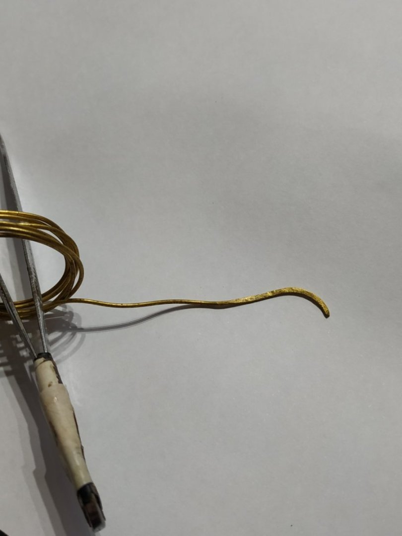
Iron Strap:
1.6x0.53mm.
Hammered from 1mm copper wire.
As well as the crank, similar to the aft of the Railing, it has an upward curve so the aft end sits on the Breastwork Rail.
Used copper blackening solution.

-
-
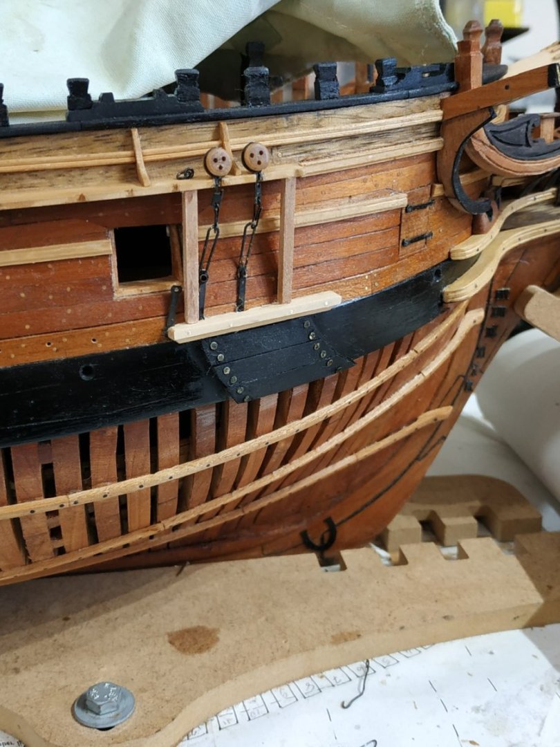
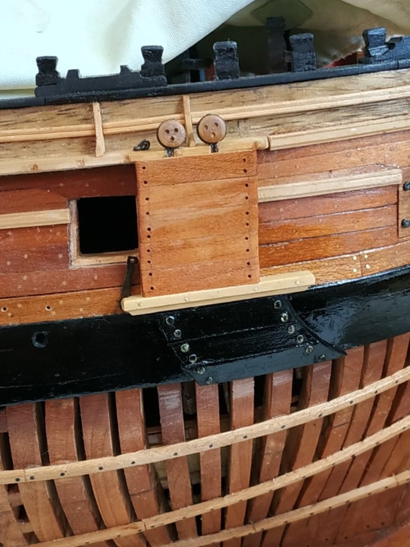
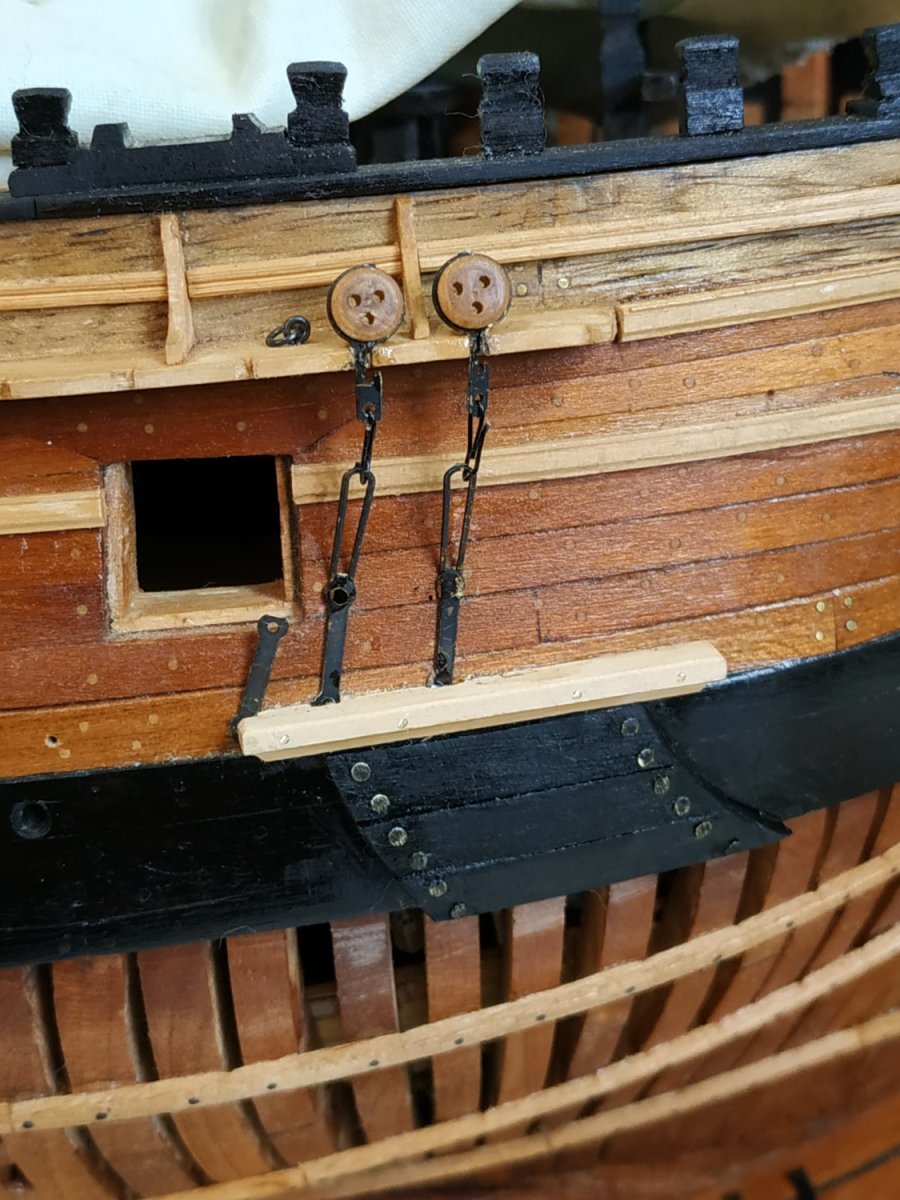
Fore Channel Deadeyes and Chains.
Sizes of Deadeyes: 5.3 and 3.71mm
Chains . 4 parts: Upper link enclosing deadeye
Middle link- os variable length
Toe
Preventer plate.
TFFM explains how to make these. I will use my parts box and purchase more as required.
Billboard, Bolster and Lining.
These protect the ship’s side from the anchor flukes.
Lining -
3 planks 1.33 mm thick, overlying the Wale.
The curved side forms a radius centered on the Catshead.
Bolster-
Rests on the Wale, above the Lining.
41.34x4.24x3.71mm deep
Inner surface fays to ship side, and is scored to fit over the Preventer Plates
Cross Section is chamfered so the lower edge is flush with the Lining.
Billboard-
Supported by 2 stanchions, 2.12x2.65mm wide, between the Bolster and underside of the Channel.
Planks 1.33 mm thick

- Prowler901, bruce d, scrubbyj427 and 5 others
-
8
-
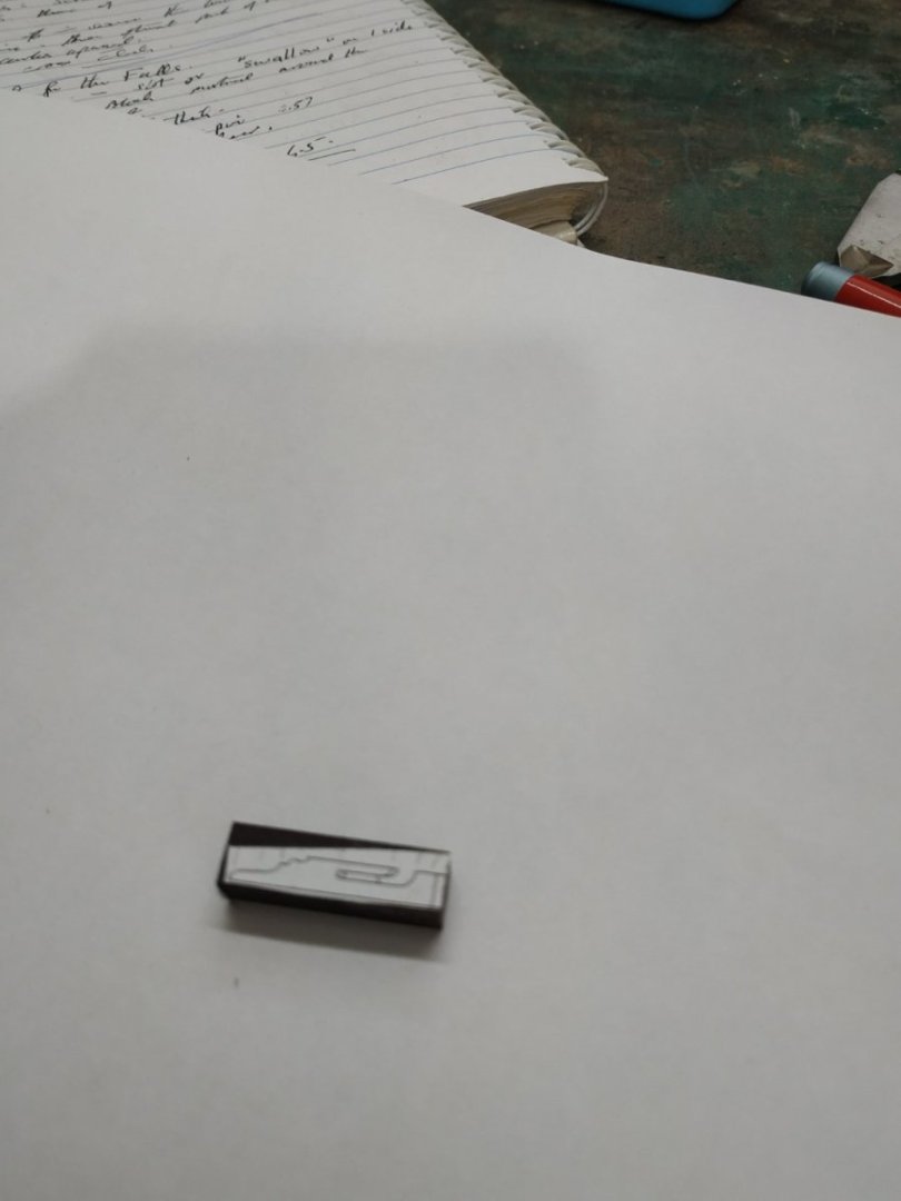
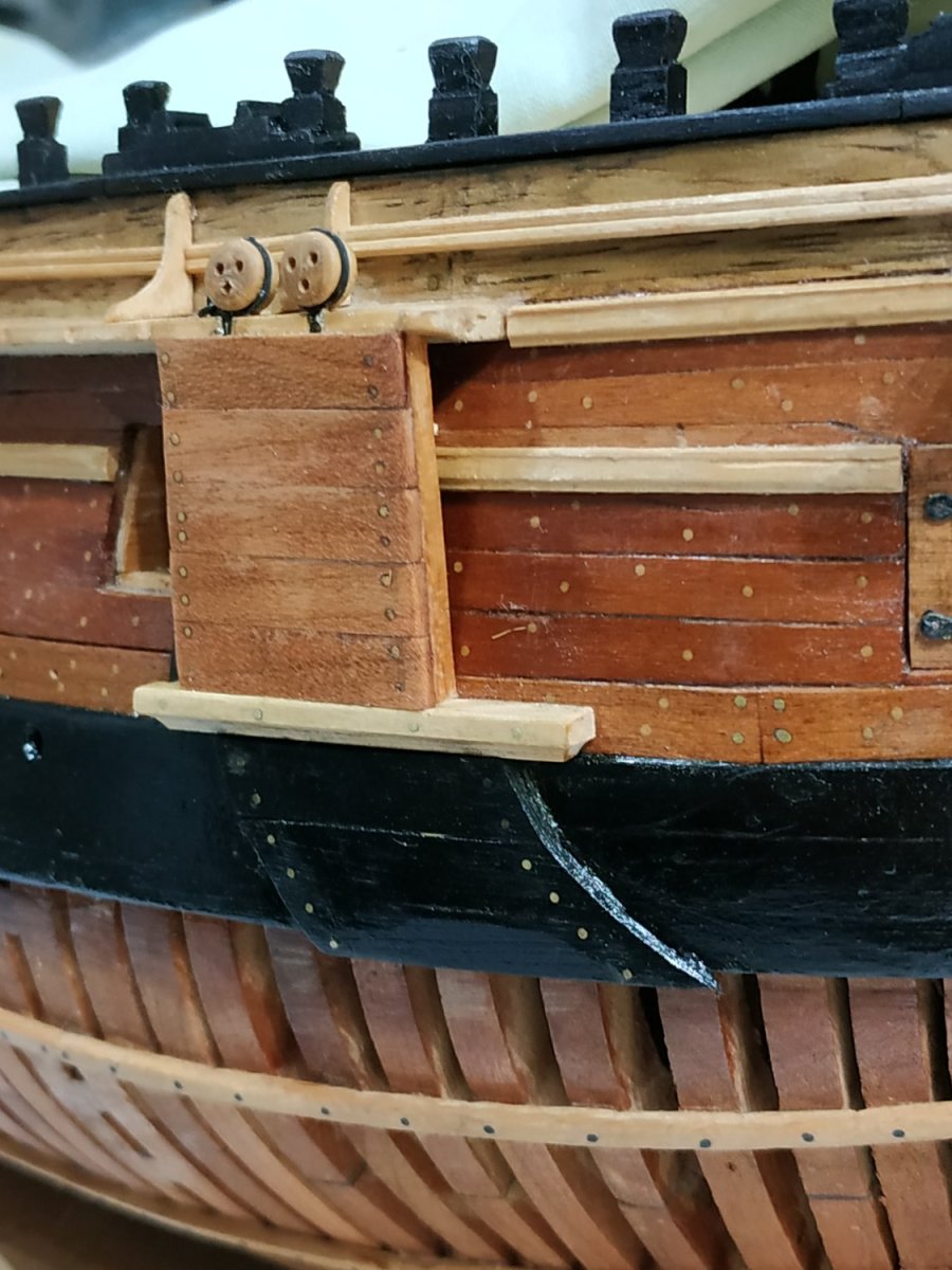
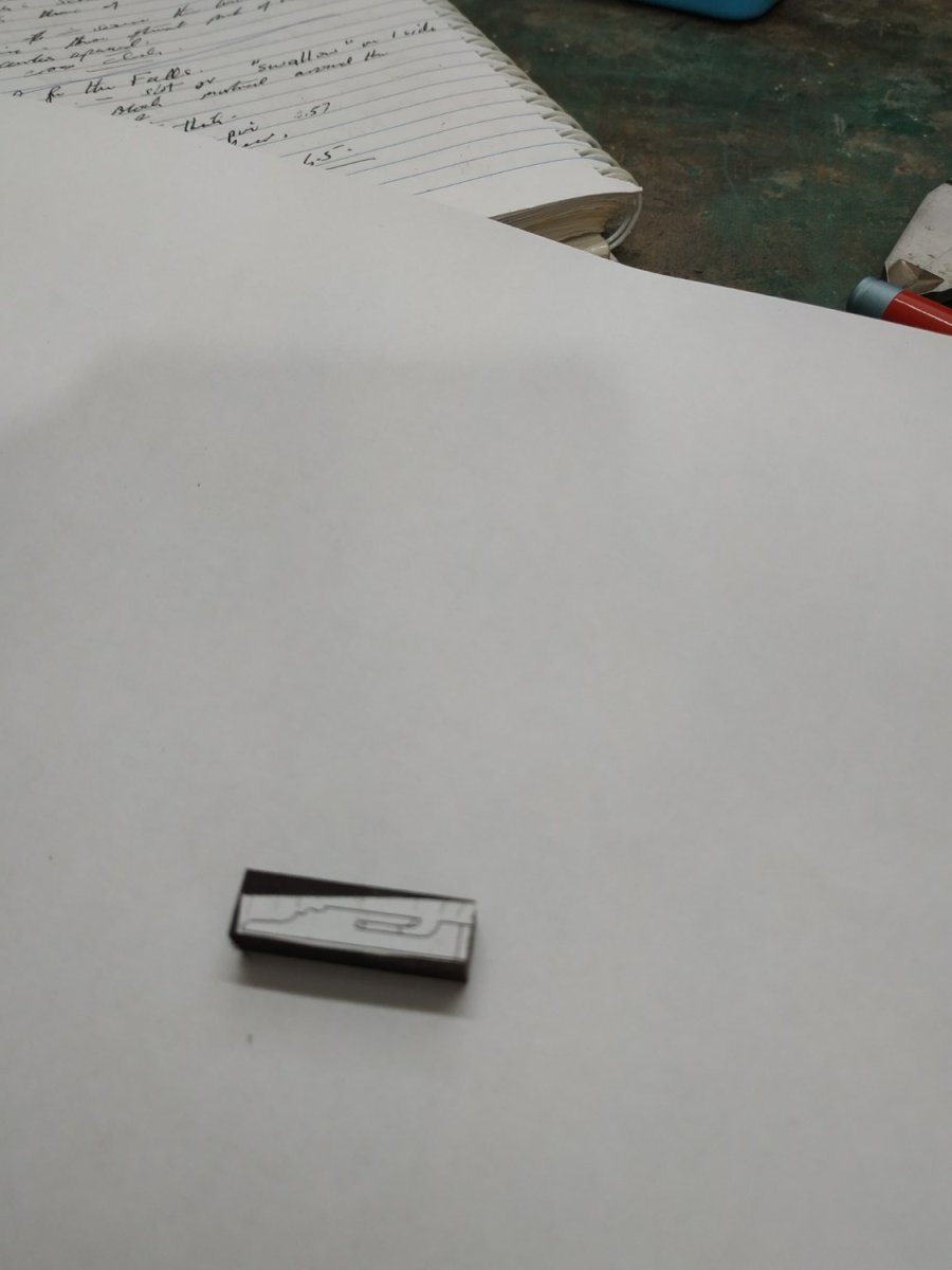
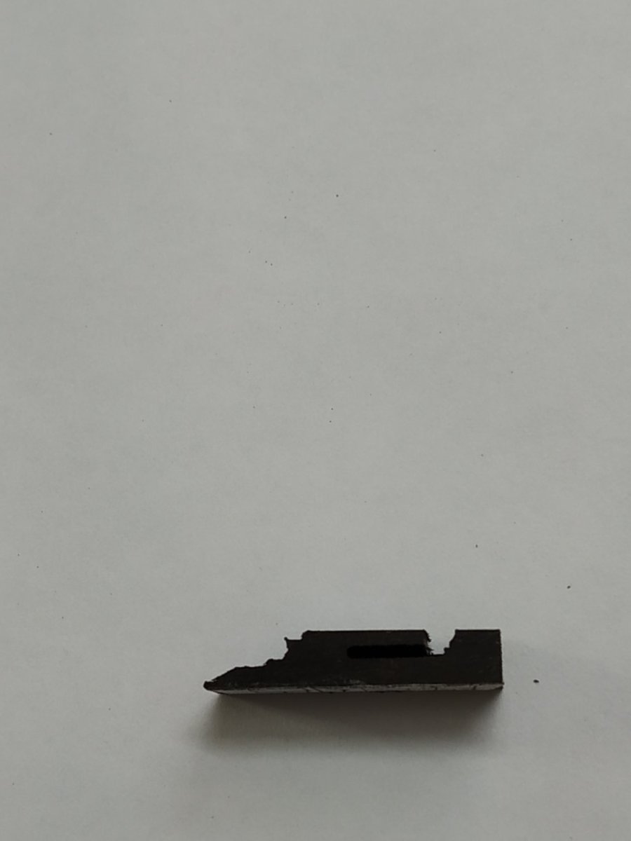
Fish Davit Cleat
(Thought I’d make some parts out of order while working on the Planksheer)
Above the 1st port. Width 4.77. Length 24.5 with a slot for Davit 8.48.
Made as the previous block- pattern and milling.
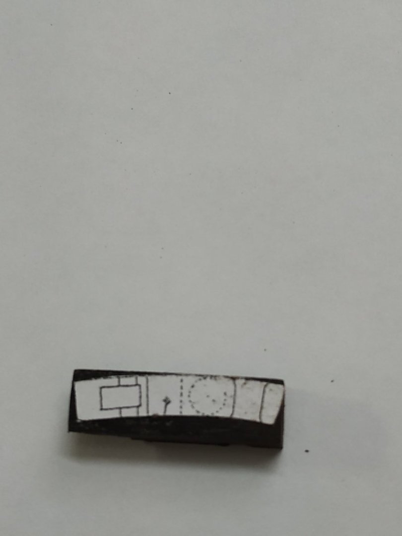
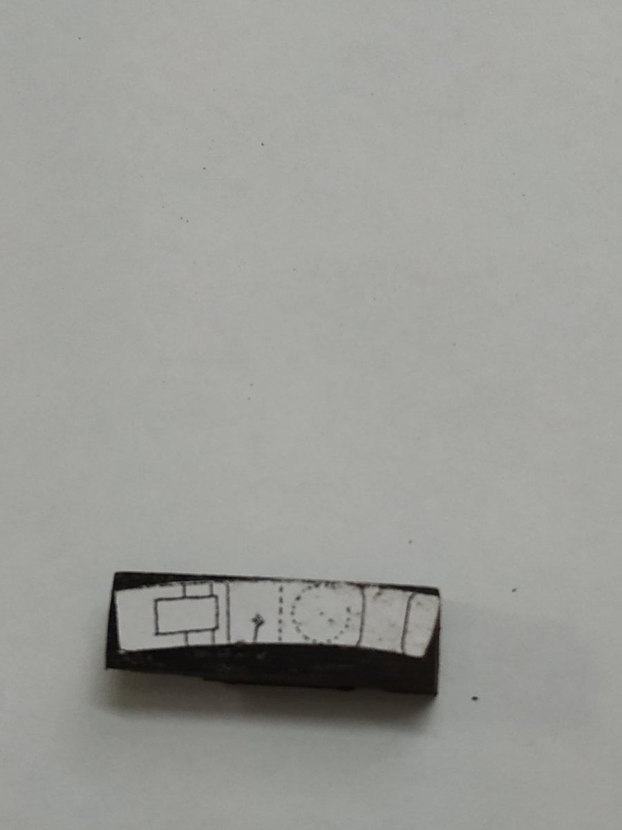
Fixed Block for Main Mast
Shown on Atalanta plan. Almost opposite the Mizzen Mast.
19.8x 1.2 high x 5.3 mm with a slot for a sheeve 1mm wide.
Timberhead enclosed within the aft section.
Fixed Block for Main Brace
Similar to Main Sheet Block, but 4x4.24 mm wide-
The aft “tail” fitted around the Outer Side Counter Timber.
Thinner sheeve (0.53) set at angle. I wedged the piece in the mill vice at the required angle and milled the slot “straight”

-
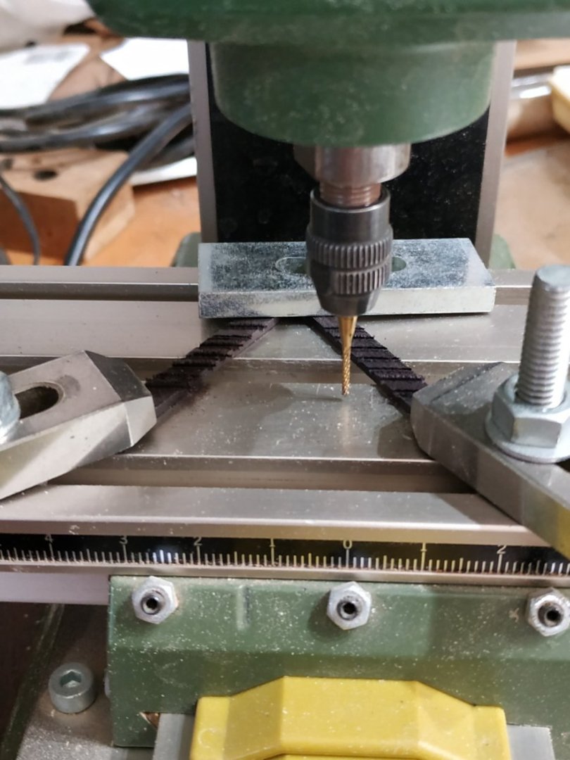
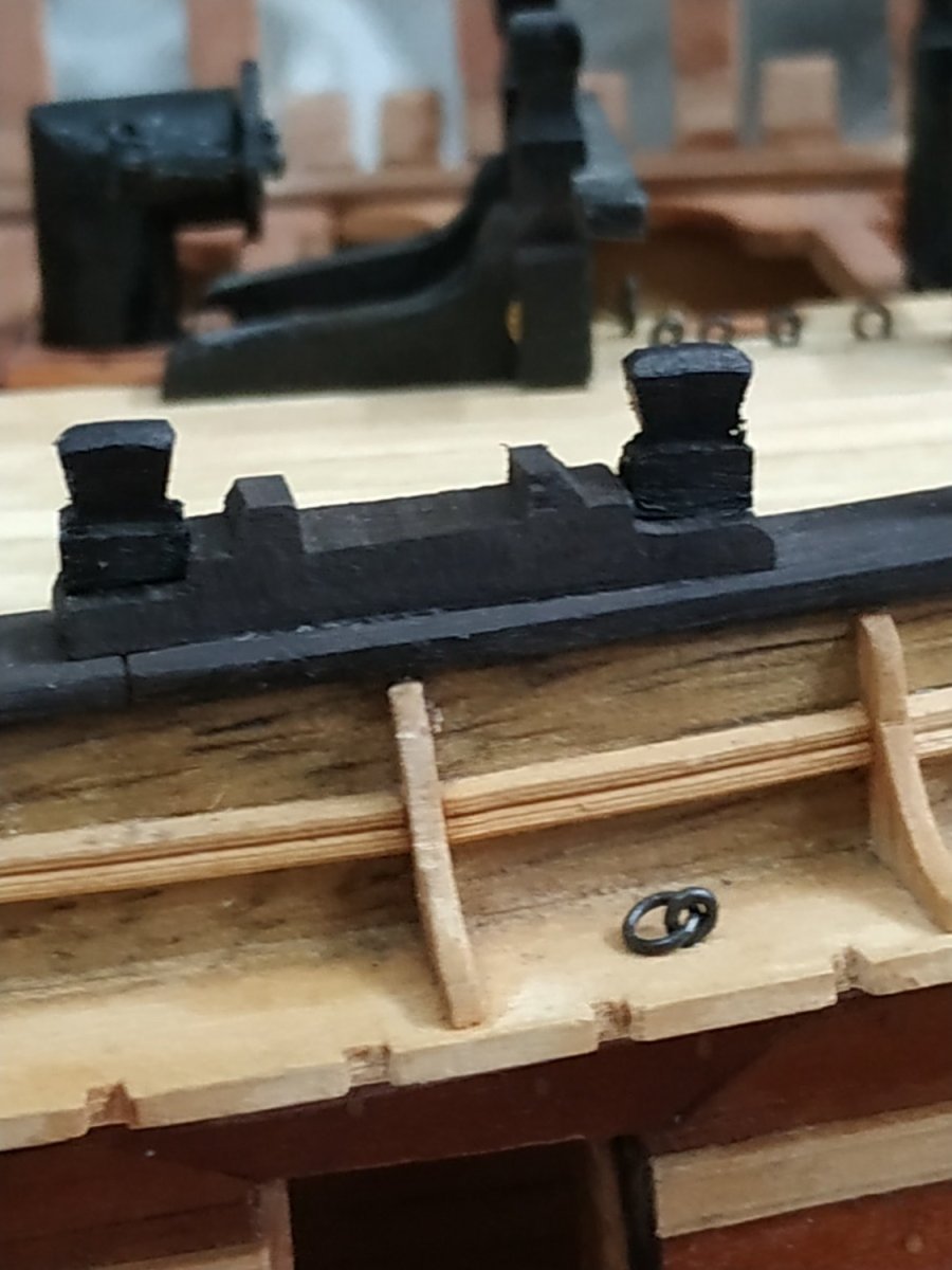
The Timberheads.
15 per side. Position as per Profile and Framing plans.
Size and shape given in TFFM ch.3.30 of vol. 1
4.24 mm wide and 2.65 deep.
As before, milled a groove on the angled strip (another strip wedged under one side) on both wider sides, then using the jig, matched the “thin” sides using a file)
These are also blackened to match the Planksheer.
The Quarterdeck Planksheer was fitted in the same way as the Forecastle Planksheer at this stage to allow the Timberheads to be fitted.
On the unfinished port side, blanks are fitted to represent where the extended frames should have been left.

-
-
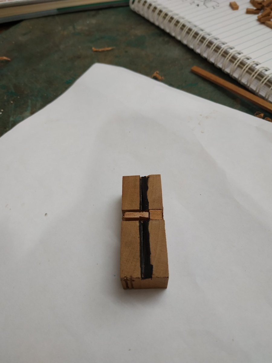
Cat Block for the Falls
This is a type called a “snatch” block because it has a slot or “swallow” on 1 side.
The “tail” of the block is mortised around a timberhead.
It is curved and coloured to match the Planksheer.
Size: 4.77 mm wide and 3.71 nn thick.
It contains a Sheeve, 4.24x0.75 mm.
To allow for the curve, I took a blank 6.5 sq.
Using a pattern, roughed out the side profile with the mill. Also used it for the slot and curved entry.
*Mistake* - cut the profile curves at right angle to the block. When I later shaped the curve (using another pattern ) to follow the Planksheer curve, realised that the profile should be at rt. angles to the curve. These were redone.
The other Timberheads will be fitted onto the Planksheer, and therefore, rather than mortise one into the Block, simply attach one onto it. (allowing for the thickness of the block at this point).

-
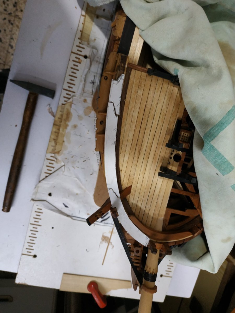
Planksheer of Forecastle
TFFM suggests making it in 2 parallel pieces as the Breast Rails, but as I have not yet made the Timberheads, this isn’t necessary.
The Planksheer is 1.33mm thick. It overlaps the combined width of the hull wall.
Using a card pattern taken directly from the model. The length is divided by 2 or 3 scarph joints.
I found it easier to fit the aftmost section. This covers a Hance. I subdivided the piece- hollowing a square piece to cover the Hance, shaping the outer surface after gluing in place. A short straight piece, before shaping the next curve in a similar fashion. The rest fitted and shaped.
As before, the wood didn’t lend itself to shaping a molding, so I simply chamfered it.
For the scrolled Terminal, I added a 2mm cylinder-shape.
The Planksheer should extend to cover the Bowsprit Cross Chock, but mine is too high - or rather the Bulwark is too low. I decided to leave this as is.
(Personal note. I’ve been on holiday and haven’t worked on the boat for a month. Brain and hands feel “rusty”. Do others find this?)


- CiscoH, James G, giampieroricci and 8 others
-
11
-
Seats of Ease
Just the forward pair.
The Discharge Tube fits in the space of the Gratings of the Head, made for that purpose. The shape is a parallelogram.
The walls are 0.53 mm thick. Each face is given as 4.77 across, but I made it “to fit”.
The inner wall rests on the Lower Rail-the outer face shorter to allow the outflow. The two other sides of height allow the whole assembly above the Gratings to be 7.95mm.
I made them in situ, stucking them separately into the Gratings gap, and sanded the top combined surfaces to be horizontal.
The Seats, also 0.53 thick, are 7.42 sq. with a hole 3.71mm diam.
The seat shape is also a parallelogram.
The False Rail and the parts of the decorative Rails of the Bow previously removed, are now cut to length and replaced.

-
The Eking Rail
The continuation of the Cathead Support.
In my plan,Atalanta, this extends above the center of the Hawse Bolster. (there is no 1st Head Timber)
The first job is to fay the inner surface. This is a significant curve. I remembered my pin jig that made it easier.
Again an oversize blank, 15x50x10mm.
With the Supporter held in place by tape,I then made the scarf joint, marked the lower curve, then the parallel upper edge. Finally the outer edge.
I epoxy-ed the joint for strength to allow the final shaping off the model.
The plan calls for molding the outer surface, but I was disappointed with my attempts on the cherrywood Main Rail,
The 3D and other illustrations show a coloured insert similar to the Covering Boards of the Head Timbers, so I followed suite


-
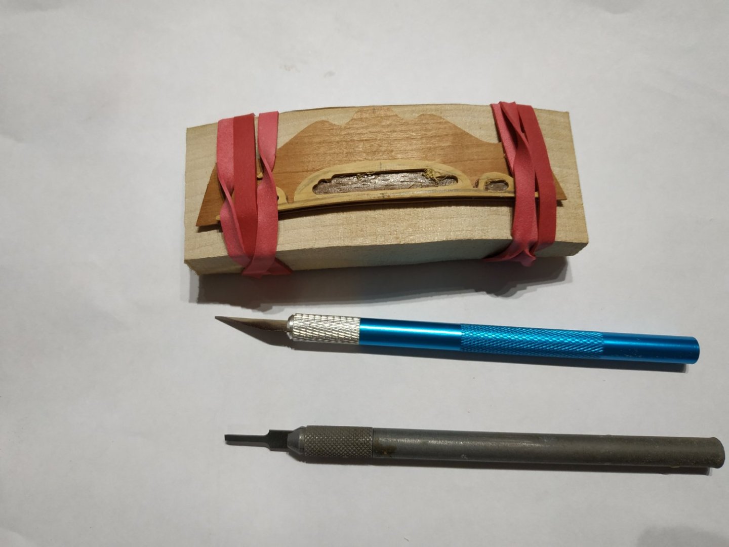
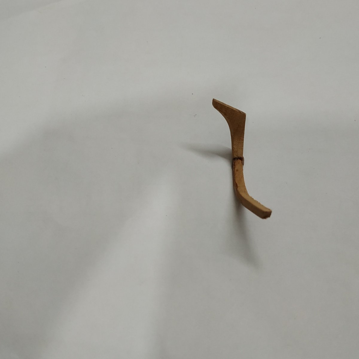
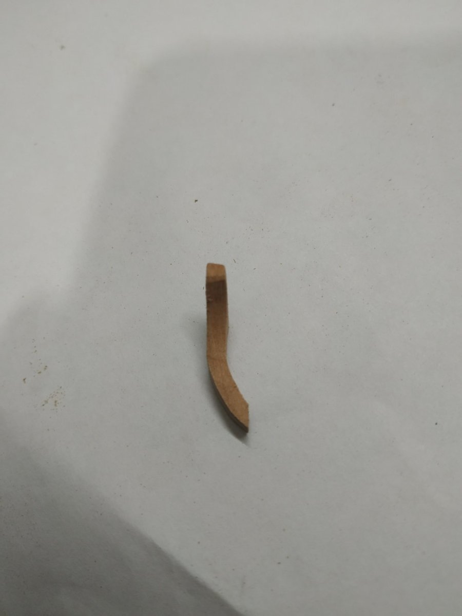
Cathead Supporter
A knee supporting the Cathead.
TFFM recommends cutting out a paper pattern to follow the AFT curve and stick it (photo glue) in position on the Bow. This is an excellent idea and simplified the repositioning of the piece accurately when frequently offering up and modifying the piece with its complex curves.
Although the final width is only 2.9mm, a larger blank is required.
I started with 6.5x16x25mm
I thought I would detail how I deal with various curves - possibly like others, but it might help a few.
The order these curves are made may vary, but again following TFFM this was made easy.
Start with the upper angle of the Steeve where it lies under the Cathead- in my case 110 deg.
The aft edge of the Supporter is initially vertical before curving forward. I stuck a cutout pattern (reversed) and roughed out the shape.
The Inner surface is then fayed to the hull.
The forward surface can now be marked to follow the aft, and the piece shaped and thinned with files to slightly more than the required 2.9mm
The concave curve of the outerface can be shaped, keeping said face at right angles to the aft face.
A scarf joint is made at the lower end where the Eking Rail will be joined.


-
"Do you dress to the left?" was a question tailors used to ask. I guess that I'm elderly, then.
"Yes Druxey, my grandfather told me of such a thing, but few living people have actually experienced it😉"
I actually was asked this as an immature and naïve boy of 13. My father explained what it meant, but at the time I think the tailor must have been on auto pilot as the question was irrelevant.
PS I am not elderly- elderly people are older than me.
- Knocklouder, mtaylor and Dave_E
-
2
-
 1
1
-
"TFFM suggests 56 inches (about 140cm) of line for gammoning, not 30cm"
I stand corrected. I failed to note "actual". TFFM is infallible if not always fathomable .
It is by far the best practicum/reference for any builder for this or other models
(Is there a maritime equivalent of "egg on my face"?)
-
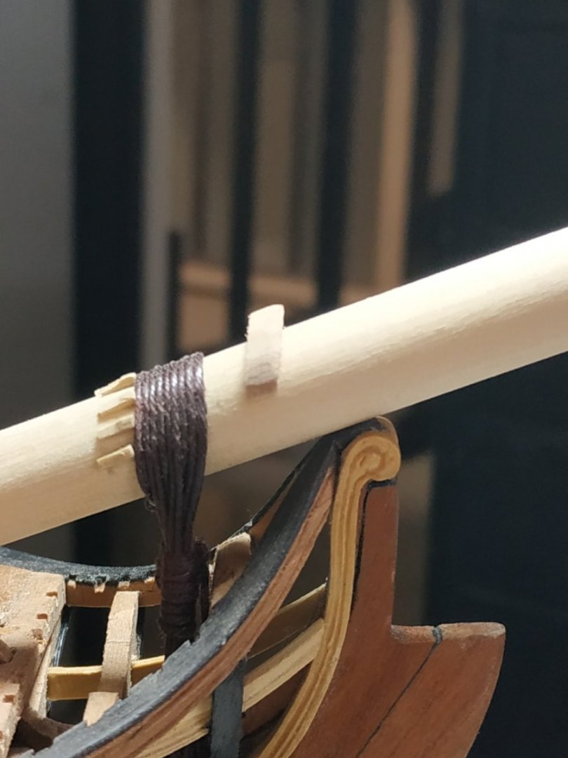
The Saddle for Running Rigging
A (less than) semicircular wooden collar sitting slightly forward of the Gammoning
Although 3.18mm width and height, a block needs to be bigger because the lower and upper surfaces are beveled to parallel the Bowsprit.
A number of holes pass through the collar - variously 4 to 7.
I made 7- diam. 0.8mm
To angle them correctly, I held the (marked) block in the vice and used a drill press.
As suggested by TFFM, bevel the underside and after fixing to the Bowsprit, the upper surface is more easily beveled, as required.
-
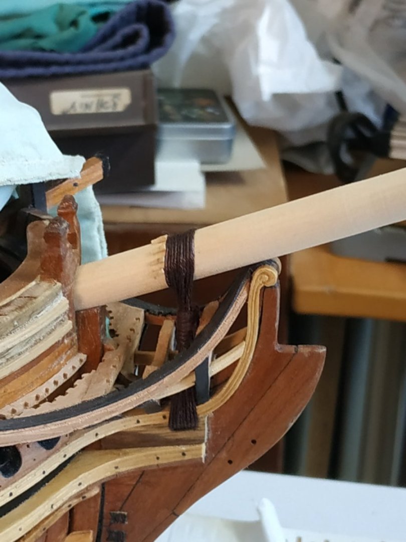
The Gammoning.
(note need to read forward to ch.15 TFFM or other reference book)
A tired line circumference 2.4 -diameter 0.8mm
TFFM suggests starting with 30cms but I found this much too short- I used 100cms.
Starting with a (pretend) eye splice, pass the line around the Bowsprit and through the eye so that it hangs to the left. (Elderly gentlemen may recall another significance for this.)
Moving through the Slot up against the fore edge, returning over the Bowsprit, against the cleats,the turns are repeated until an EVEN number of turns fills the slit.(My case=8)
The descending line is now taken between the upright turns, alternating port and starboard, interspersed with half hitches, for a similar number of turns.The loose end is half hitched through the last 2 turns.
-
Decision Time
To rig or not to rig- that is the question.
Or short symbolic masts, or none.
This was supposed to be an “undressed” model-although much remains hidden by the ribs and decks.
I intend to make a swan again, but with full planking, minimum internals and fully rigged.
Why the opening question? Well, how do I deal with the Bowsprit?
Decided short, but enough to show the Gammoning, which is very much part of the Head.
Bowsprit.
Make it long enough to include the Saddle ,about 15cms
A max. Diameter 10.9 mm- narrow forward slightly by 2mm, but aft to 9.35mm before ending in a square 6.5, narrowing to 4.5mm (to fit in the Bowsprit Step).
I used lathe and sandpaper strips.
Ensure that it fits through the Stem Head and Cross Chock.
According to the plans, the Bowsprit rests at 20 deg to the horizontal.
By some miracle, the square “heel” fits into the Bowsprit Step.
Gammoning Cleats.
A line of oblong short strips, 3.7 long and 1.06 sq -slightly wedge shape when viewed from the side.
Varied in number between 5 -9 ( I made 7)
They are fixed to the Bowsprit so that the fore edges align vertically above the fore edge of the Gammoning Slot. I used a weighted string to mark this line.
The outer pair at position 3 and 9 of the clock, the rest evenly spread.


Swan-Class Sloop by Stuglo - FINISHED - 1:48
in - Build logs for subjects built 1751 - 1800
Posted
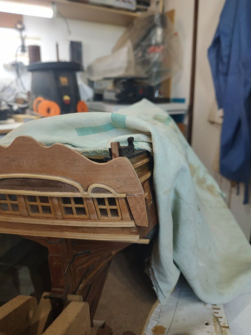
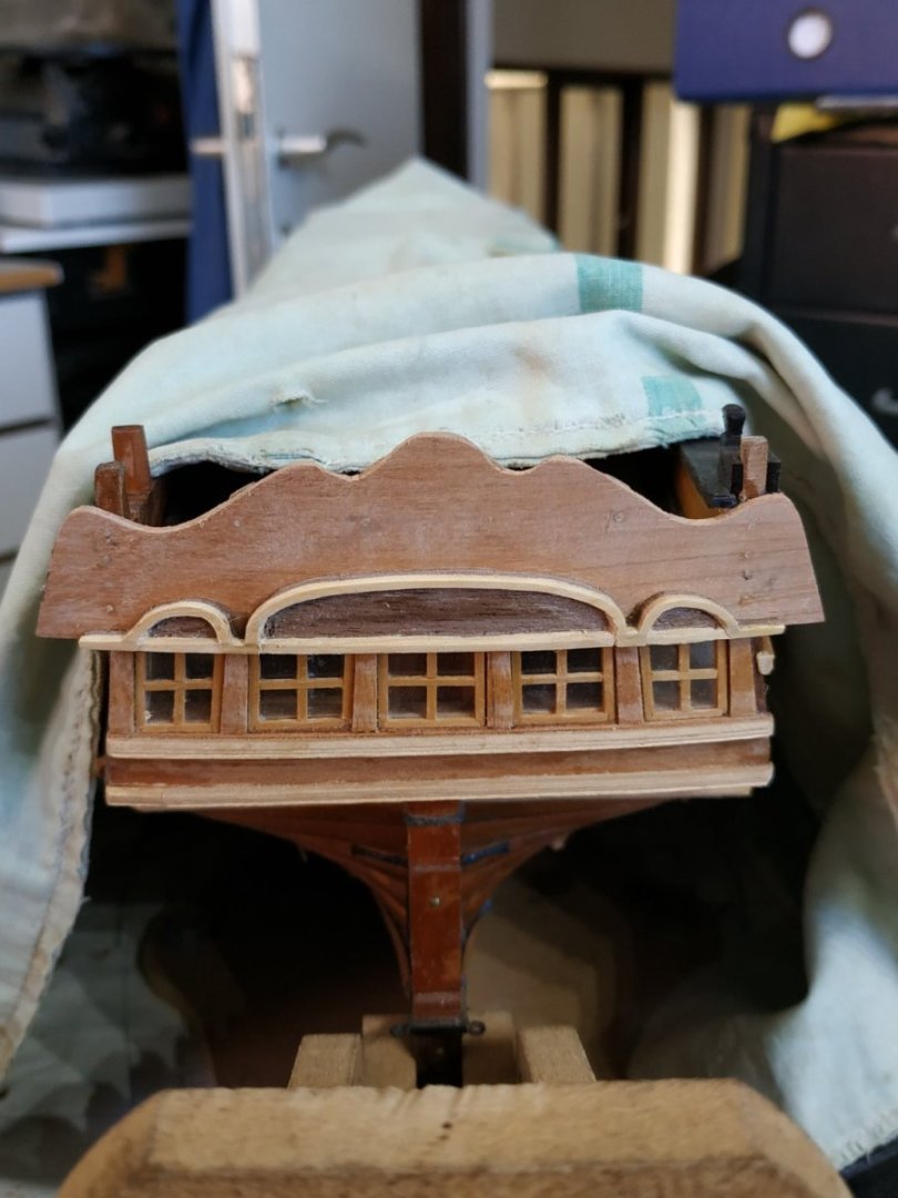
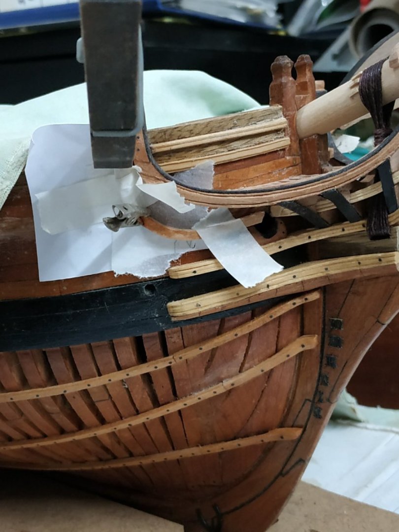
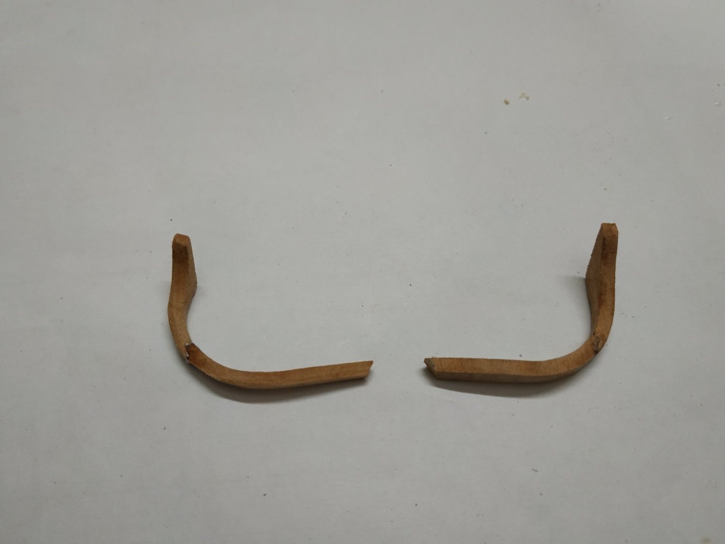
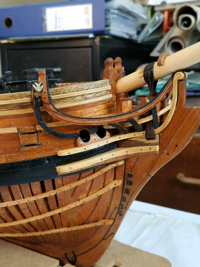
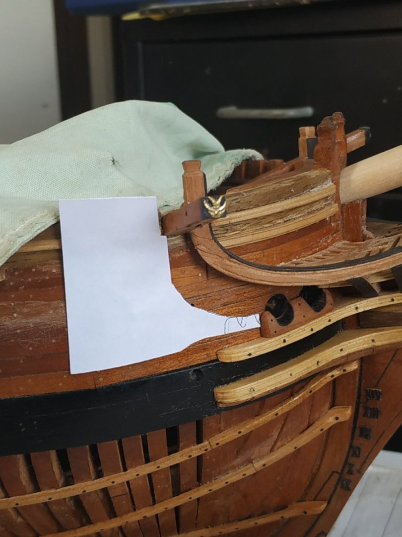
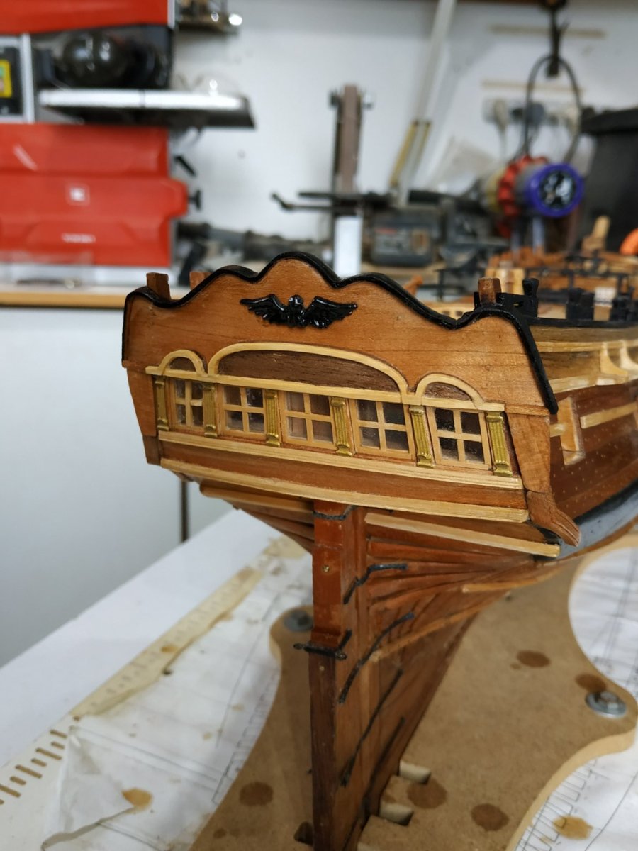
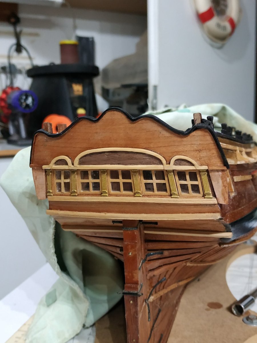
Munions and Lights
4 in parallel. The outermost against the ship’s side and so shaped.
Can’t see that dimensions are given, so made 3.60x1.35mm .
With a central space , the fore and aft sides appear to differ slightly in width.
The frames seem to be set to the back of the munions, but I found this difficult in practice.
I had totally forgotten how I made the frame, but was able to refer to my blog of May 15,2022.
The main difference was the extension of the frame into the Bell section of the Upper Stool.
This I made and fitted separately.
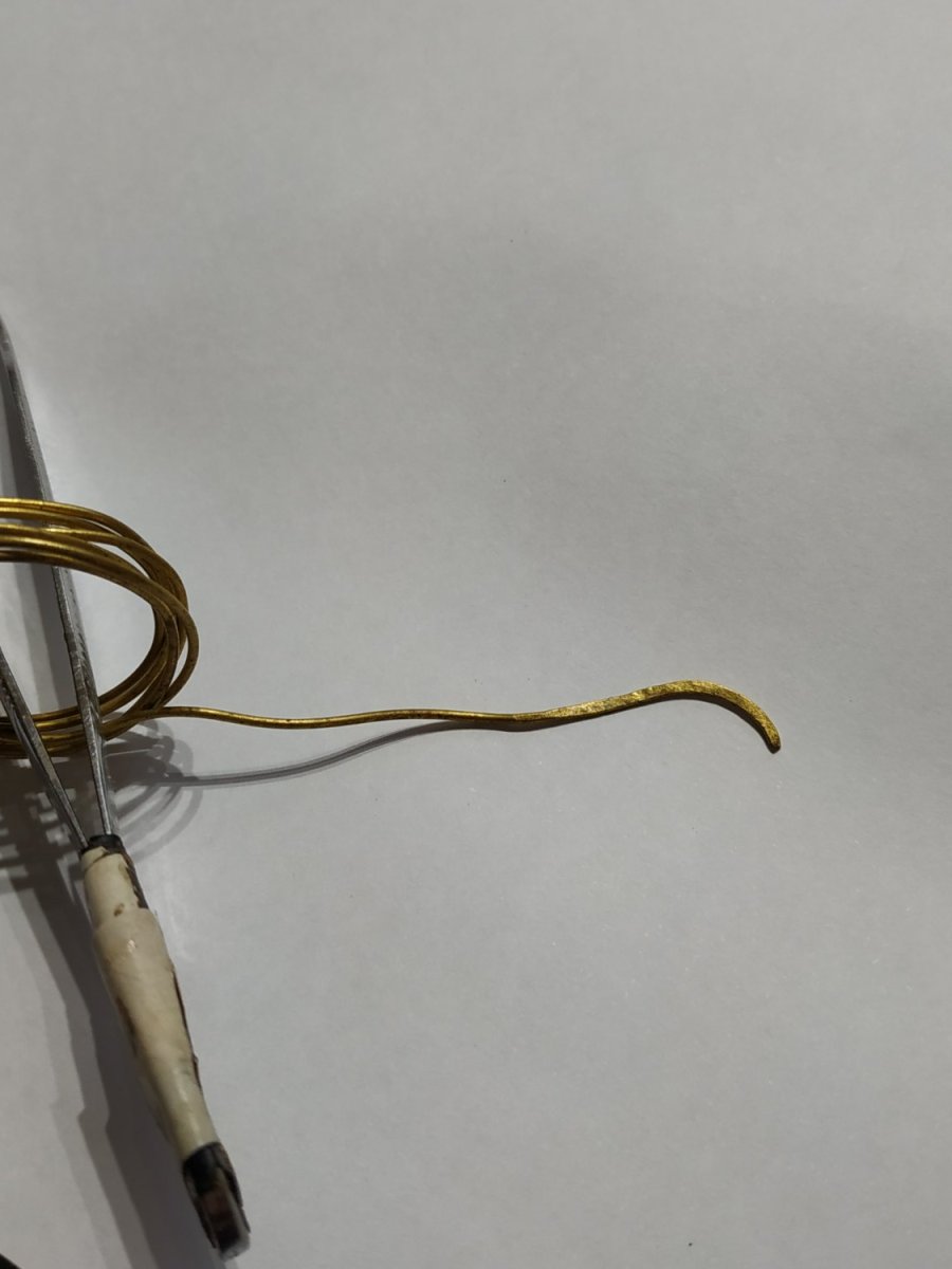
While the glue for the Munions was drying, I shaped out a block as the first stage in making the Upper finishing.
I usually soak the piece in hot water, before applying an adapted soldering iron against a wooden curve.
Because of the peculiar curve, after a quick soak, I clamped the piece to my shaped blank which allowed it to slowly take and hold the shape while still in hot water. It worked nicely.
I then fixed this separately.
The middle light was made with the plastic shaped as required above the upper rail but unframed, so that the light can be slipped into the upper frame while fitting.
The Munions and framing do not appear to be in parallel, but this is an optical illusion.
The Pilasters are again leftovers, adapted for the purpose