
Supplies of the Ship Modeler's Handbook are running out. Get your copy NOW before they are gone! Click on photo to order.
×

cog
-
Posts
8,764 -
Joined
Reputation Activity
-

 cog reacted to captainbob in Charles P Notman 1894 by Jond - FINISHED - 1:48 scale - RADIO - Downeast Four-Masted Schooner built by Percy Small
Ah yes. The problems with scale RC. If you make it strong enough it is out of scale. If it is in scale it is not strong enough. But where's the fun with no problems?
Bob
-
cog reacted to mtaylor in Licorne 1755 by mtaylor - 3/16" scale - French Frigate - from Hahn plans - Version 2.0 - TERMINATED
I've been reading and re-reading those tutorials as well as the Jim Roberts' book on planking. And I should add.. Dan's wisdom has helped immensely with this.
I don't have issues, at this point, with the lining and spiling, or the bending and fitting of planks. What has been giving me fits until I started sketching out the area is where the stern ends of the planks start to come around the end of the hull to start landing on the transom. There's a fashion piece that covers the counter and the ends of the hull planks. After re-studying, re-thinking, the Licorne drawings just weren't detailed enough as I was cutting the fashion piece short by about 1/8" or so. Just enough that I was seeing gaps and not a happy camper with the appearance. I've delved into a couple of French frigate monographs and have sorted out that that the lower end of the fashion piece and plank ends are hidden by the quarter gallery drop.
The solution was simple once I figured out what was needed...
Now that the laser cutter is sorted out, I'm focusing on finishing up the wide planking... sanding... and hopefully pictures in a couple of days. After this, it's the garboard strake and then lining off the rest of the hull for the narrow planking. A bit of the pain to have several different widths of hull planking but it's sorting itself out.
-
cog reacted to archjofo in La Créole 1827 by archjofo - Scale 1/48 - French corvette
Hello,
thanks for the nice compliments. Here is the continuation from boat building:
-
 cog got a reaction from popeye the sailor in RMS Titanic by popeye the sailor - Academy - PLASTIC - 1/400 scale
Nace (according to Sam) save on the paint job Pops. You should have known about the numbering ... always something tricky dicky when you least expect it. Lucky we're at MSW, there's bound to be someone whom shows up with a solution ...
-
 cog got a reaction from GLakie in RMS Titanic by popeye the sailor - Academy - PLASTIC - 1/400 scale
Nace (according to Sam) save on the paint job Pops. You should have known about the numbering ... always something tricky dicky when you least expect it. Lucky we're at MSW, there's bound to be someone whom shows up with a solution ...
-
cog reacted to Jond in Charles P Notman 1894 by Jond - FINISHED - 1:48 scale - RADIO - Downeast Four-Masted Schooner built by Percy Small
next stage....bend the sails argh.
I have found the real dilemma here as I tip toe through new territory. How to build at 1:48 but be rugged enough to sail. examples.
While moving the boat in and out of car and in and out of shop for the float test....oops there goes the rail. This oops is without masts even being stepped. . as I tie off blocks for halyards, I kept pulling them off. I changed two of the throat halyards triple blocks to wire staples up through the cross beam and bent over. A little over kill. I left the others thread as they did not break....yet Yes I am using thread...not lines. mostly 70% poly and 30% cotton from Joann. I bought better for stays. There is also no way I have a vehicle that can move this boat. I do have a small boat trailer for my 12 foot sailing dinghy but really. I will need a friend with a pick up hopefully with a cover As I go forward I smile and remind myself of my goals. I want a 1:48 scale schooner in most things. I want every line that functions. Yes the major sails' sheets are a little big, but so far that is all. I just need to to do my best and get in the water. If I can build it, I am sure I can fix it, so here we go setting the sails bent.
I have moved the boat to my study.....only about 10 feet away from the shop. It has nice daylight and overhead task lights that help with vision. I can work on all sides, and using the strapped stand I can also tilt either way for port or starboard tack. That way gravity helps move the sails out of the way if I need to see the deck etc.
here we are starting the process. most of the work was done off board to sew the lower sails in place and trim the spars. The stay sails are held by jack stays and are done in place. before we can work forward I needed to trim out the bowsprit and jib boom details I found from the details on the CORA CRESSY plans on all block sizes, chains and lines. The light chains were either 3/4 or 7/8 and like the stays us lashing with dead eyes. i used light wire to make all the strops with shackle connections for pinning to eye bolts. the larger chains get turn buckles. This was fun for me. After turning the martingale I had to do more real soldering. The bottom cap needed a double band forward and single aft.. I also fully soldered the band holding the jib boom down to the end of the bowsprit. It worked but boy I am really new at this task. I used 24 gauge copper for the shackles and painted the chain in place to get it to look like galvanized chain. The turn buckles are a bit shorter, and the two unconnected ones needed longer clevises to allow pinning to the bees. I held up on installing their chains until I run the upper stays that hook to the sides of the martingale and run to the prepared lashing dead eyes. I just want to hand fit the line of the chain and then drill the eye bolts....yes i am chicken finally here is the attached foresail. It's a big milestone for me. The sails are threaded up the stay that you can see is lashed to the staple forward of the bitt. I found a new problem with the top sails. they each have clew lines that raise the clew up and over the brace stays [ not yet installed]. they are like the tack lines [ also up and over the brace stay] and sheets that run either to port or starboard pins. All three sets have one loose to leeward and one tight to windward. For RC schooners the stay-sail rides with the gaff and is like an extension to the lower sail. [ I shall add little lines for that function too] Thus these lines can never be tight; what to do. here you can see the clew lines that run from tack up through the the block held through ridge line boss ring through the sail [ see picture] and then further through a lizard to the peak block and down.
here you see the three attachments for each side. the two lines on the side rail are peak halyard and clew line. the two lines at the mast rail are sheet through the leader block aft and the tack to the middle pin.
My plan is to run the tack and sheets continuous through the rings and then leave a bit loose. the clew must just be loose because there are separate peak blocks. After sailing is over I can tighten them up.
here one can see the tight fit for lines where the lower main deck carries the leader blocks for the foremast beside the forward deck house. I believe using the Bluejacket pre-stropped blocks makes this doable and rugged. finally here we are for progress.... 9 sails on and 6 more to go cheers -
 cog got a reaction from mobbsie in Bomb Vessel Granado 1742 by mobbsie - FINISHED - 1/48 - cross-section
Mobbsie,
Didn't know you listened to yourself Looking forward to those fragile wedding bands mate
-
cog reacted to popeye the sailor in RMS Titanic by popeye the sailor - Academy - PLASTIC - 1/400 scale
thanks for the good word gents! I recap the comments from the previous posts
John: we see this all the time......it's not really a surprise. the build was going too good.......there had to be a chink in the armor somewhere. I wish I could say that it's seen less in wood modeling, but I've heard my share of sad tales, where measurements were off and laser cutting had gone awry. the two wall pieces {as for most of the wall parts}, sit in a slight impression of a slot in the deck. they have the tabs as well, so there only one way to fit the parts. it's a pretty easy fix.......
Sam: that's my thought on the funnels as well. I'm going with that in mind. I haven't looked at the link yet......I wonder what scale it's in?
George: I've done kits before that also had the numbers on the parts.......never gave it a thought. just chalk it up to me being me I got lucky with the over spray.......I had a few occasions where it didn't go as planned. it was worth a try....what would have been the worst thing....a repaint? I only mixed up 1/4 oz of the paint..........I have very little left.
also...thanks to all of you who hit the like button
-
cog reacted to popeye the sailor in RMS Titanic by popeye the sailor - Academy - PLASTIC - 1/400 scale
you think I was finished with those railings????? ohhhhhhh noooooo, this kit isn't through running me through the ringer yet I found out that there are two other parts that go along with the bow and stern railings. the railings were cemented on the bow section.......minus the tip of the railing.
on with the stripe.........the hull was masked and redied for paint.
man.....I pressed the living crap out of the tape.....to insure that the plastic's detail was sealed away, to give me a good line.
and then my heart stopped! since it was such a small area to paint......I figured that I didn't need to mask up the entire hull.
I think this should be a warning to those who are just starting out with their airbrushes.......never misjudge over spray!
I put into action, a technique I used to do long ago. got a clean rag and some thinner and gave it a gentle wash over.
the bottom paint has been on there about a week now.......plenty of time to cure. the yellow overs pray is new and hasn't cured yet.....as long as you don't scrub, it should come off very easy. gentle strokes in one direction and move very fast.......don't dwell on any part of the hull, this is what it looks like now.
the stern railings were cemented in place at this time. you can see the section that's missing at the very aft
there is some repair and touch up to be done with the stripe. I tried so hard to get the tape to stick completely. I made the stripe a wee bit wider than it probably should, but I think once it's touched up and the deck / bulwark assemblies are in place, it should look OK.
I left the name plates at the bow open for the name decals.
-
cog reacted to Jim Lad in RMS Titanic by popeye the sailor - Academy - PLASTIC - 1/400 scale
Looks like this is starting to get a bit complex, Popeye. I always thought that kits like this fitted perfectly - shows my ignorance of the the type!
John
-
cog reacted to popeye the sailor in RMS Titanic by popeye the sailor - Academy - PLASTIC - 1/400 scale
with the remainder of last week liquidating into one complete bummer {getting pulled away from the table to do other chores}, I figured I'd try and redeem myself. Tuesday though, revealed a few things I wasn't pleased about. I guess i'll just have to figure it out when I get to them. looking ahead in the instructions, I still find the way they want me to do the deck assembly, a bit weird.......I'm not seeing a good outcome. so I decided that I would work on getting the decks on the hull, and do the railings and stuff afterwards.
first thing I did was get the stand together. once the yellow stripe is done, it can be cemented on the stand.
the wire additions on the cranes were painted Steel........a bit more touch ups need to be done yet.
....and this is where thing started to get muddy. I assembled the main parts of the funnels.......I didn't add the other parts yet due to paint reasons. I wish I had. as we know, they are numbered 1 through 4. I took it for granted that there might be embossed part numbers on the insides of the funnels.......there aren't. they are not all the same either, so now it's pretty confusing as to what order they are to be at. I did find one saving grace......I noticed that one of the ladders was a tad shorter than the others. I'm thinking this is #1. the others differ in height as well.......a very tiny increment.... .5 to 1 mm. this changes my plans just a little bit, since they all need to be rigged before the decks are assembled.
the other bummer is with the front fascia of the decks. there are two small sections of wall that the base of the fascia is to be cemented to. the problem here, is that the width of the base doesn't match the wall spacing......it falls short about .5 mm
the bridge deck and A deck can be assembled along with the mid bulwark parts.......I'll have to figure a way to fix the width problem, before this can be done.
the railings on these two deck can also be done after they are assembled.
-
cog reacted to captainbob in Bertrand by Cathead - FINISHED - 1:87 - wooden Missouri River sternwheeler
Considering you are trying to align all those hundreds of matchsticks, I think you've done a masterful job.
Bob
-
cog reacted to Cathead in Bertrand by Cathead - FINISHED - 1:87 - wooden Missouri River sternwheeler
I have made it through some very tedious work on the Bertrand, getting the hull framing virtually done. Here is how she looks now, though you will have to look closely to see changes from the last photos:
What has happened since:
Finished framing bow & stern, including inserting lots of little futtock braces into all the bilge corners. A very fiddly task I am glad to be done with. Finished interior bracing with various stringers along sides and bottom of hull. This includes the reinforced keelson, built from multiple layers of wood. Sanded and shaped frames, including the tight turn of the bilge. Will likely need to do a bit more touch-up before planking, once I start testing the lie of planks. Doesn't sound like much, but it was a lot of detail work without major visual progress. All projects have this sort of task. But the hull is now solid and sound. What's really neat is, it's just as flexible and strong as the real thing. You can take it in your hands and flex, bend, and twist it like a snake's skeleton, which is just how the prototype boats needed to be to navigate the sandbars and shoals of the shallow Western rivers. I may have to take a short video of this to share; it's a very different architecture from the rigid hulls of ocean-going vessels.
Here are closeups of the bow and stern:
I haven't yet trimmed the upper ends of the futtocks, so they look very ragged. I won't do so until all the decking beams are in place and I'm sure of the final geometry.
I closed in the final part of the sterm with a piece of scrap wood on each side, to provide a better surface for planking. This area won't be seen in any angle, so I decided to make it easier on myself.
I'm not a master craftsman, and it shows in certain areas. For example, here are two less-than-ideal results along the hull:
At top, you see the upper internal stringers. The deck beams are supposed to rest on this. But I didn't get it installed perfectly level on both sides, it wavers up and down a wee bit in places. So I filed notches into it where necessary to get the deck beams to sit evenly across the hull. It won't be noticeable in the final product, unless a real craftsman is looking really closely, but I was annoyed to discover my error.
At bottom, you see an example of futtocks that didn't come out straight. Trying to clamp all of these perfectly onto the stringers was difficult, and in places I didn't succeed. More annoying sloppiness, but only noticeable close up. Once the model moves back from the eyes, it all blends into the whole. Still, were I to do a hull like this again, I would be more careful somehow. At least, I'd like to think so.
What comes next? Before any planking begins, I'd like to install the interior framing and the deck beams. This will strengthen the hull more for planking, and the planking also depends to an extent on where the deck beams are. This is because Bertrand has guards, extensions of the deck that reach beyond the hull, so the guard support beams need to penetrate the planking. I've decided it will be easier to install the deck beams first and plank around them, than plank first and cut a bunch of holes/slots for the guard supports.
The decks beams themselves will be a bit fiddly, as the deck has a slight camber that I'd like to recreate. This will mean some very careful installation of internal framing to get the camber right, and produce a deck surface that doesn't look like a wavy fun-house floor or skateboarding rink.
Working on this will likely take me a few more weeks before any update comes; this continues to be a very busy time of year in the real world. It's been strawberry season here on the farm, and all that picking does a number on my back, making the idea of bending over a model workbench for fun just a bit less attractive.
In other news, the weather lately has been good for wrecking steamboats. Tons of rain in the Missouri River basin, the river rising rapidly, carrying lots of fresh woody debris into the channel. Were this 150 years ago, it'd be a deadly time for boats like the Bertrand. Not to mention, almost impossible to work their way upriver into the flood currents.
-
cog reacted to captainbob in Symphony by Omega1234 - FINISHED - 1/200 scale - 112' Ketch
"I think I have to accept that trying to achieve the 'essence' of the engine rather than the detail"
You caught the essence and it looks good.
Bob
-
cog reacted to IgorSky in Symphony by Omega1234 - FINISHED - 1/200 scale - 112' Ketch
Hi Patrick!
It looks very cool!
Have you the photo of the original engine?
Best Regards!
Igor.
-
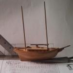
cog reacted to Omega1234 in Symphony by Omega1234 - FINISHED - 1/200 scale - 112' Ketch
Hi everyone and many thanks for all of your likes and comments! Greatly appreciated.
Well, I've finally started on the internal bulkheads. First and foremost, I've started on the engine room which is situated in the centre of the ship. The funny little red thing that you can see in the first photo is, in fact my feeble attempt at the ship's engine. I'm a bit embarrassed about it, because it's so tiny that it was difficult to get any detail on it. If I can, I'll try to take some photos of it (that way, we can all laugh at it!!!).
Anyhow, I'm just glad that I've been able to start on the internal work, because that's what I enjoy the most.
All the best!
Cheers
Patrick
-
cog reacted to michael mott in Friendship Sloop by captainbob - FINISHED - 1:48
These things take longer than we think they will. I am doing a little model work, just not on boats at the moment.
Michael
-
cog reacted to mtaylor in Licorne 1755 by mtaylor - 3/16" scale - French Frigate - from Hahn plans - Version 2.0 - TERMINATED
Thanks all. At this point, one more row of planks, some sanding the "wide" strakes will be done. I'll do some sanding since it's pretty rough and then some pictures. Soon I hope.
I'm having a headache with where the planks roll and twist to land on the counter. If I can get the area to look right to my eyes, I'll be thrilled. I think I have it figured out.... I just need to do it. Now if life would stop getting in the way, I could make some real progress.
-
cog reacted to wyz in Licorne 1755 by mtaylor - 3/16" scale - French Frigate - from Hahn plans - Version 2.0 - TERMINATED
Mark I know first hand how much you can agonize when doing the spiling. It's important to do it right if the run of the planking is to have that proper look. Believe me when I say I feel your pain. As I read the posts on your build log I'm struck with how sage like Dan (shipmodel) is when he says that the measurement between strakes and battens, while important, are just a starting point. Battens are continually adjustable guides and not rigid inflexable borders. Furthermore he said trust your eyes in conjunction with the battens. He gives GOOD advise. Doing this work, to some extent, is feel. I always found I had to play around with the tape a good deal to get through this process and have it look right. Stay with it friend, you'll find the answer.
Tom
-
cog reacted to JesseLee in Syren by JesseLee - FINISHED - Model Shipways - scale: 1:64
Haven't posted much- have been plugging away at the upper planking around the gun ports. This has been going slow for me. I can only work on it so long & my pain sets In & I have to stop. Anyway I noticed that there was too much of a dip in the planking curve on one side. The planking wasn't lining up at the same height on both sides. A little alcohol & a thin blade got this corrected. Re-glued it & continued on.
Oh, almost forgot to show the method of caulking I ended up using. I tried to do the pencil but I kept indenting the edges of the planks because I couldn't seem to maintain an even pressure as I marked the edges. I also smudged it all over the place. I experimented with a few things & settled on this. I use a makeup sponge applicator thingy my wife dropped on the floor & paint the edge with some black paint. I smear this with my thumb to keep it thin. This seems to work well for me.
Every day as I work on the ship one of our dogs, Lucy, faithfully lays at my feet as long as I work there.
-
 cog got a reaction from robin b in HMS Dragon 1760 by Siggi52 - FINISHED - Scale 1:48 - English 74-Gun ship
Great progress again Siggi. Deck's planking looks very sharp!
-
cog reacted to Siggi52 in HMS Dragon 1760 by Siggi52 - FINISHED - Scale 1:48 - English 74-Gun ship
Hello,
the planks for the the quarter deck are laid. Now is also the upper gun deck dark and only in the ward room is some light.
Here I'm sunning the fresh oiled deck and showed the ship the great ocean.
The layout for the first bulwark is also ready and installed. For the next days I have to cut the beams for the poop deck.
Regards,
Siggi
-
 cog got a reaction from Jack12477 in Bomb Vessel Granado 1742 by gjdale - FINISHED - 1/48 - Cross-Section
Some work just must be done by hand. Stunning Grant ... really beautiful work ... So now the remaining builders get an errata on the building instructions ... (proudly presented by G. Dale)
-
cog reacted to Beef Wellington in HMS Snake by Beef Wellington - FINISHED - Caldercraft - Scale 1: 64 - First wooden ship build
JesseLee, Mobbsie,Carl, and the likes - thanks for all the positive comments
Continuing with the main yard:
After adding a few of the requisite blocks, it was finally time to figure out how to tackle the stirrups and horses. The instructions indicate using wire, but I wanted something a little more realistic so tried making with 0.5mm line.
Made the usual false splice into a length of line using an offcut of .75mm wire to get eye of appropriate size.
These were then lashed around the yard in the appropriate places and diluted PVA applied to add some stiffness and secure in place. A length of wire was used to try to keep the eyes aligned and clamps provided a small amount of tension while glue dried. Instructions indicate the eye should be 15mm below the yard, I reduced this to 13mm as Ifelt it looked a little more to scale, and also seemed to match up better with diagrams in the AOTS series. I also decided to use 3 stirrups per side against the 2 indicated on the plans as the spacing looked too great to my eye.
Horses were then added with yet more false splices around the center of the yard and around the cleats. The cleats were the smallest I could manage but seem to be what is required to keep to appropriate scale. The cleats are installed 1/20th of the length of the yard from the end. I had previously used paper to simulate the iron bands for the end boom iron.
Yard dryfitted. Although the stirrups and horses will need a little bit of adjusting wjhen finally in position, I'm pretty happy with the result. Now need to replicate on the remaining yards now the plan of attack has been determined. Its amazing how congested things are getting, not sure how I'll manage to get the trusses on and the sling lashing when I get there, but thats a challenge for the future.
-
 cog got a reaction from Cristiano in Venetian Polacre by Cristiano - FINISHED - XVIII century
I hope you do Cristiano, I shal most certainly follow your new log!!!