Mahuna
-
Posts
1,504 -
Joined
-
Last visited
Content Type
Profiles
Forums
Gallery
Events
Everything posted by Mahuna
-
 Thanks Druxey. Thanks Mark. It was quite a challenge, but worth it. Thanks Carl. Filing certainly is an alternative. Even with milling there's a lot of file work ahead. Thanks Ron.
 -
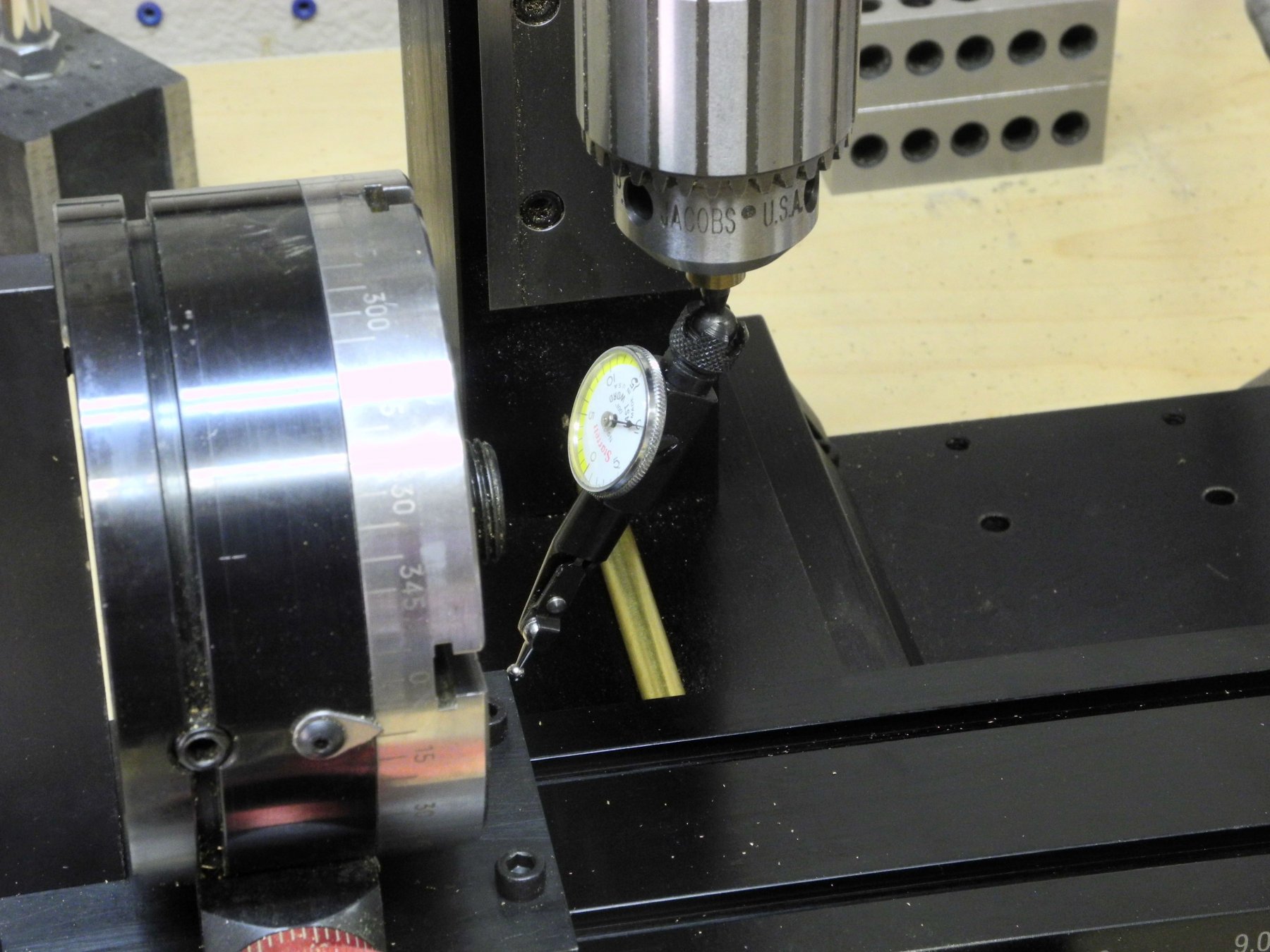
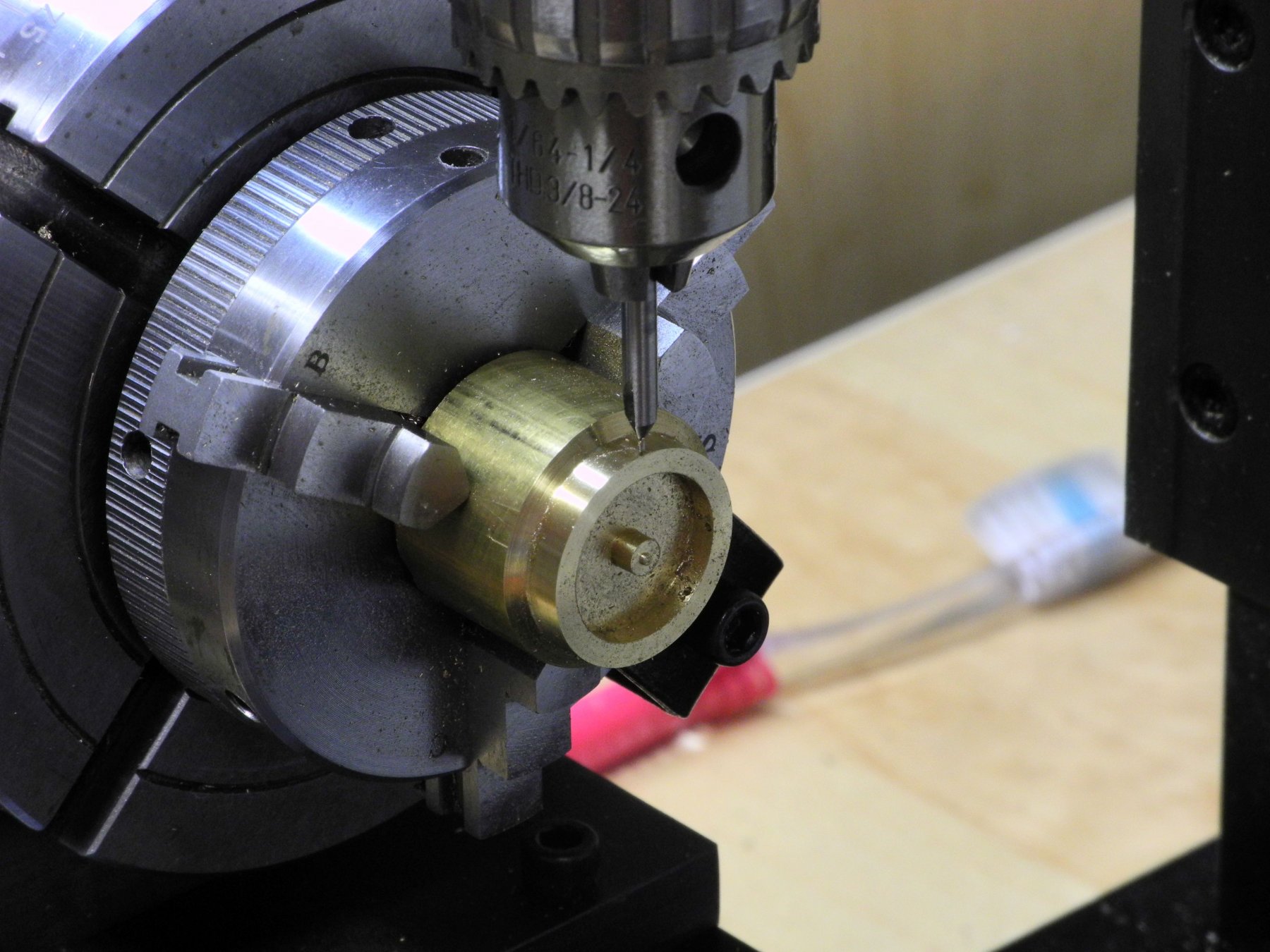
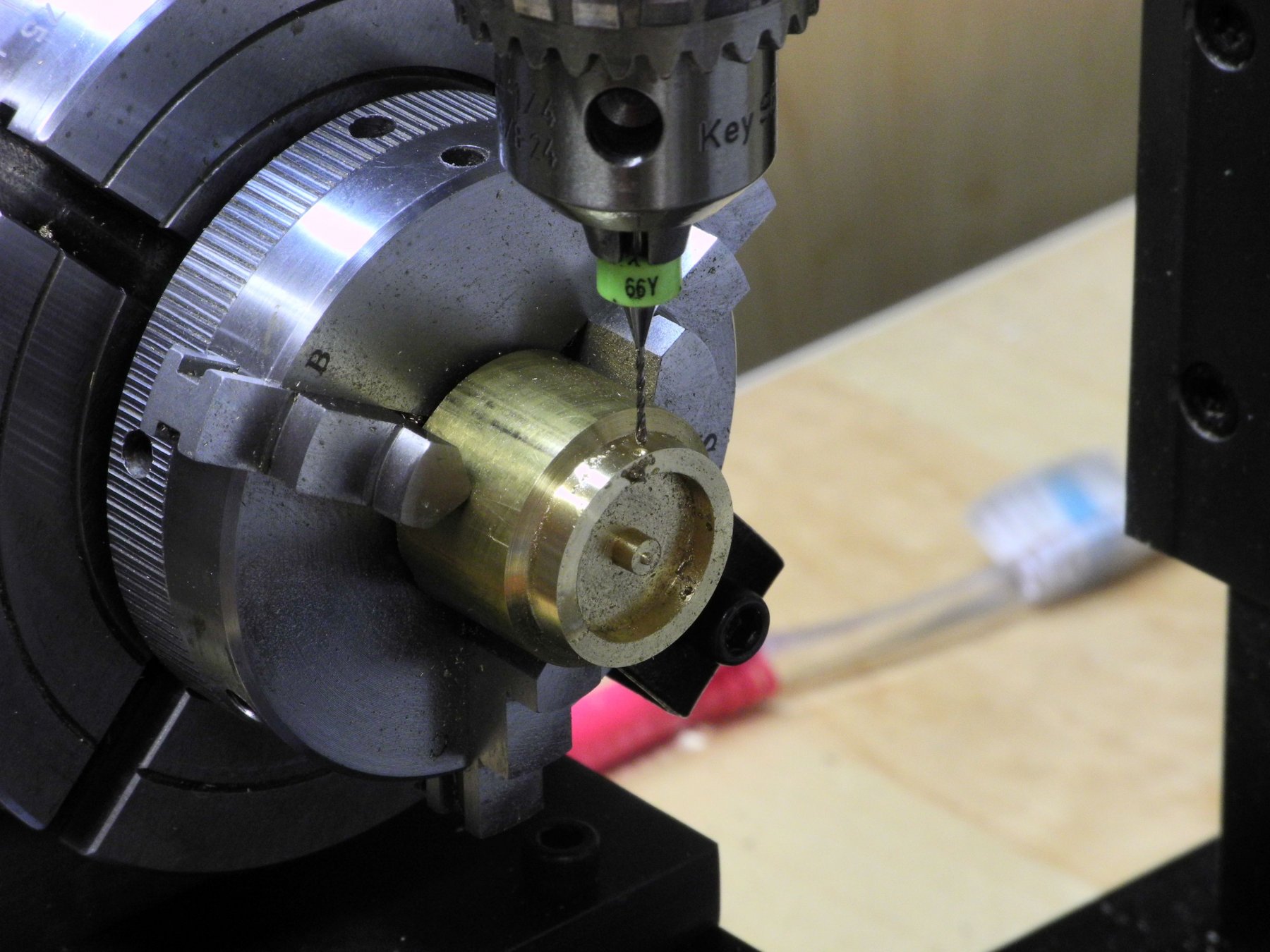
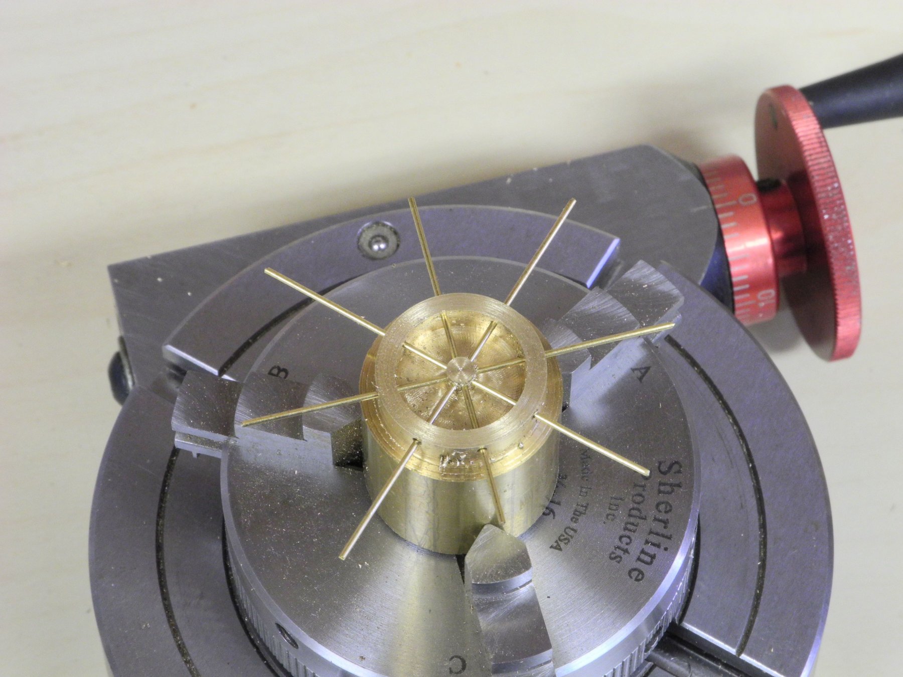
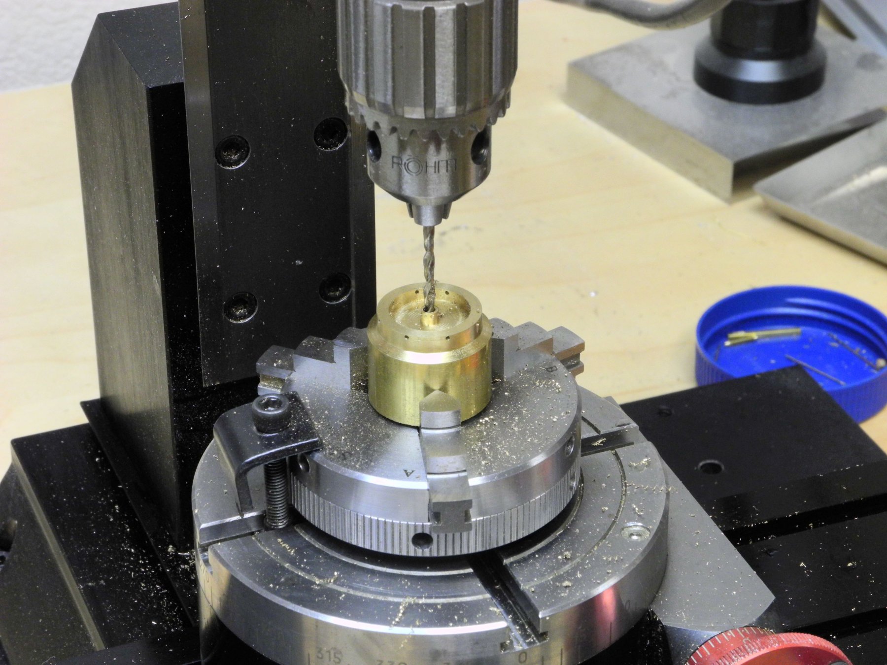
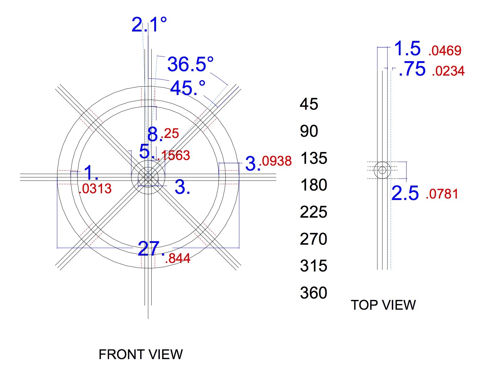
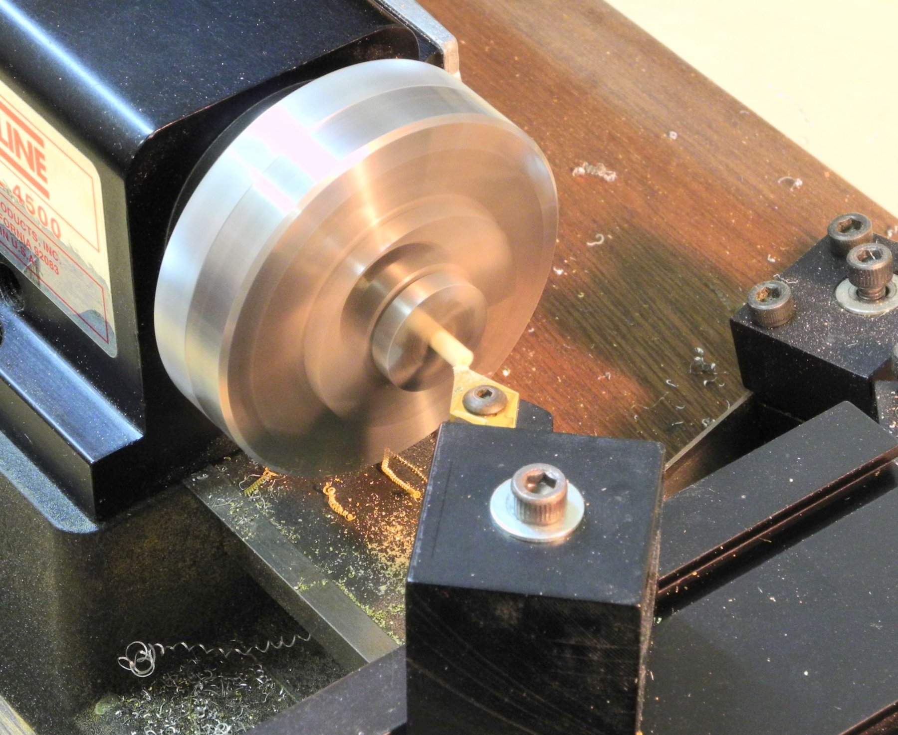
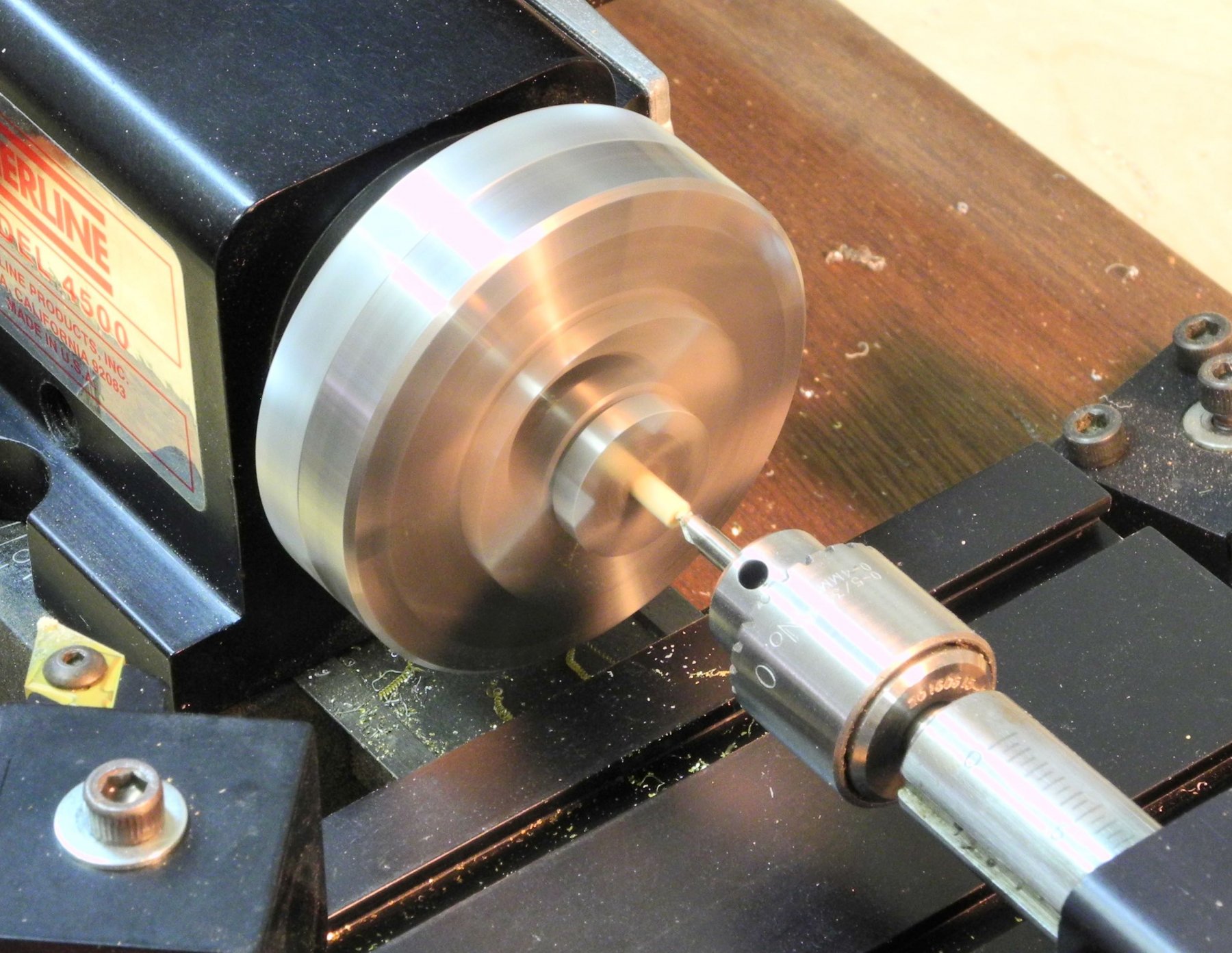
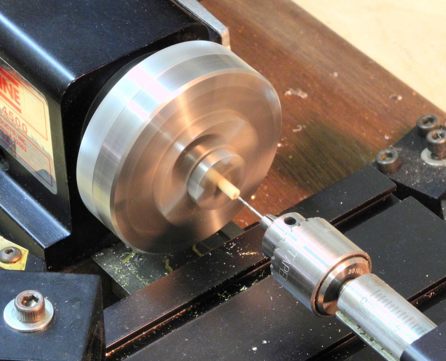
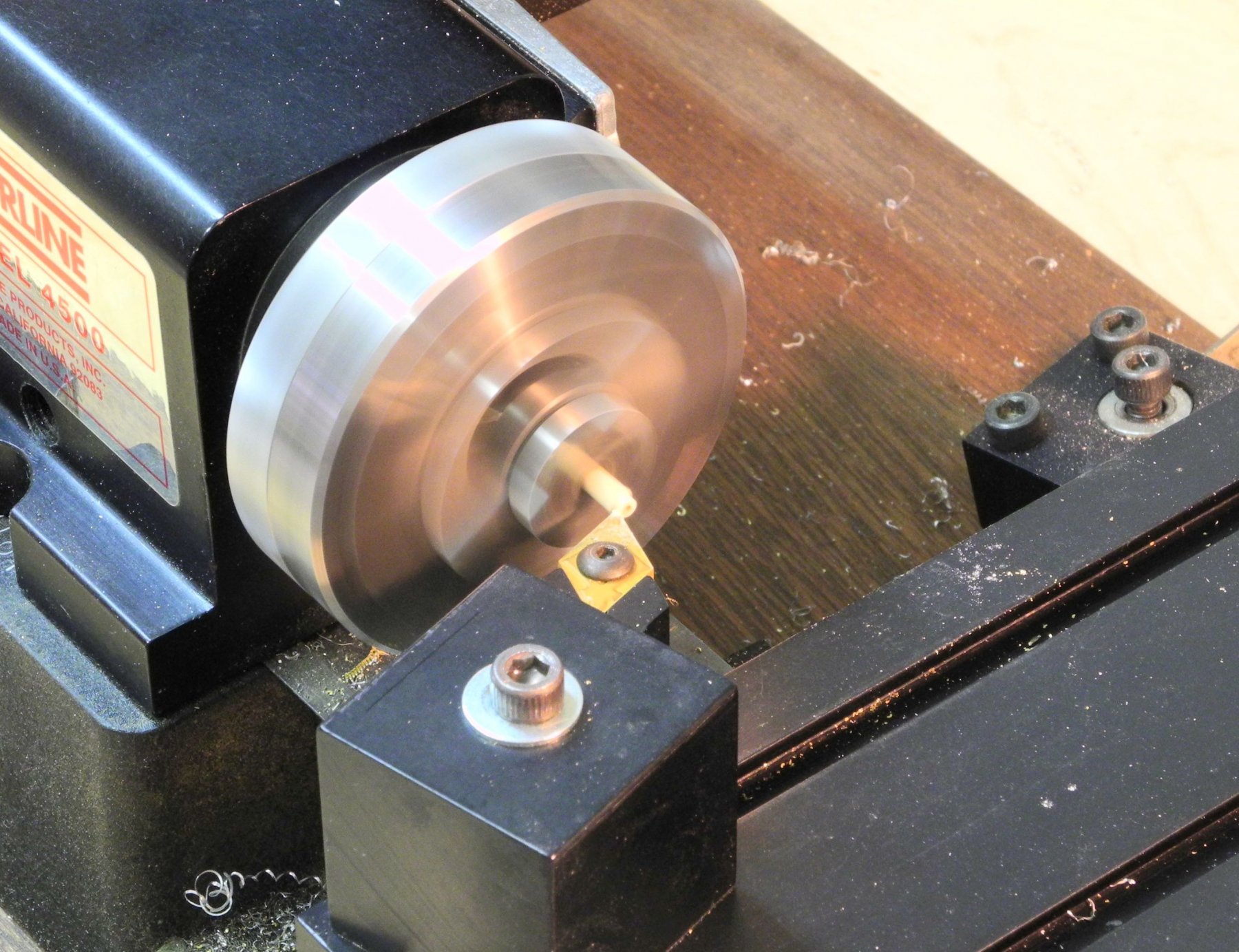
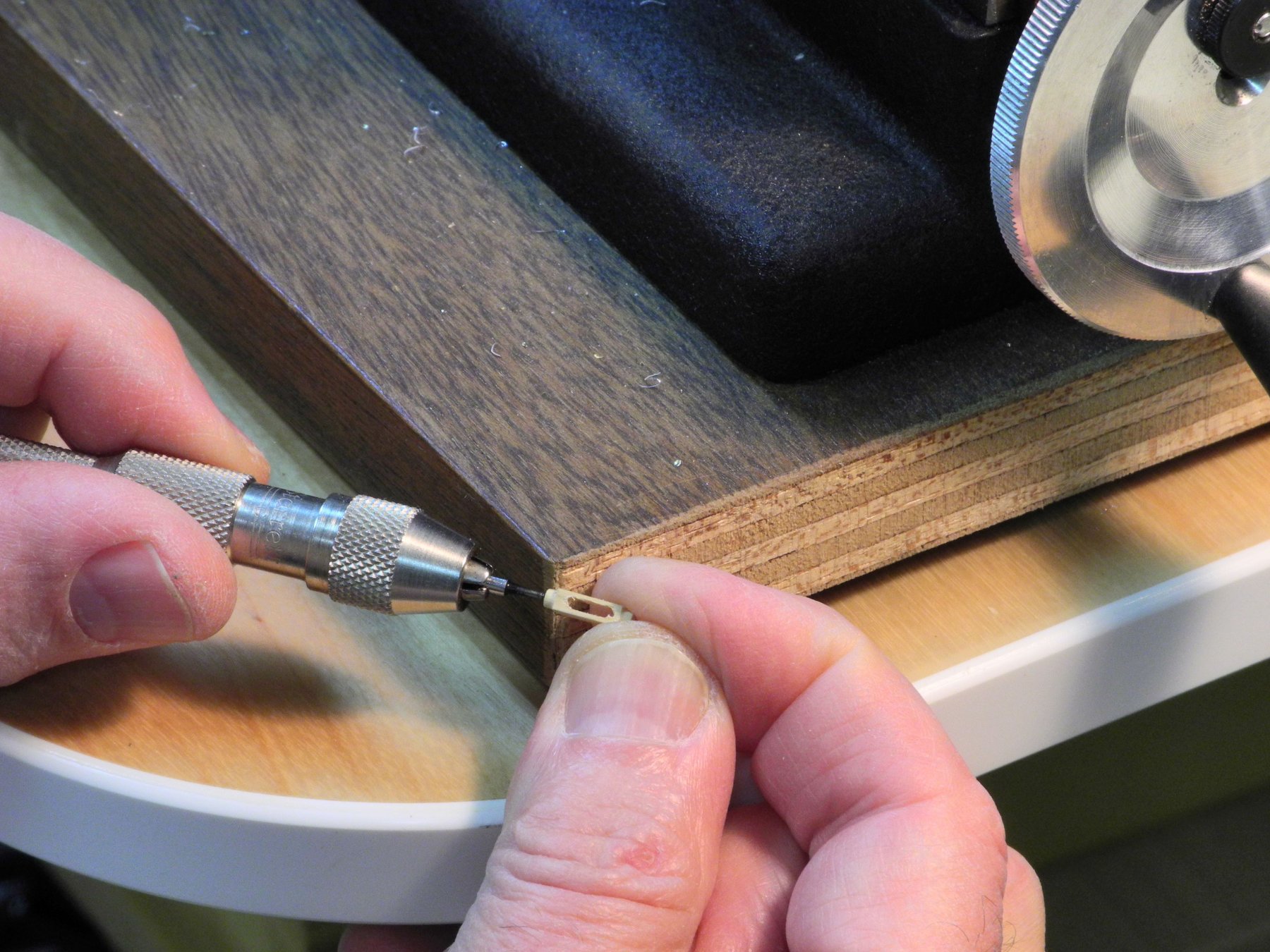
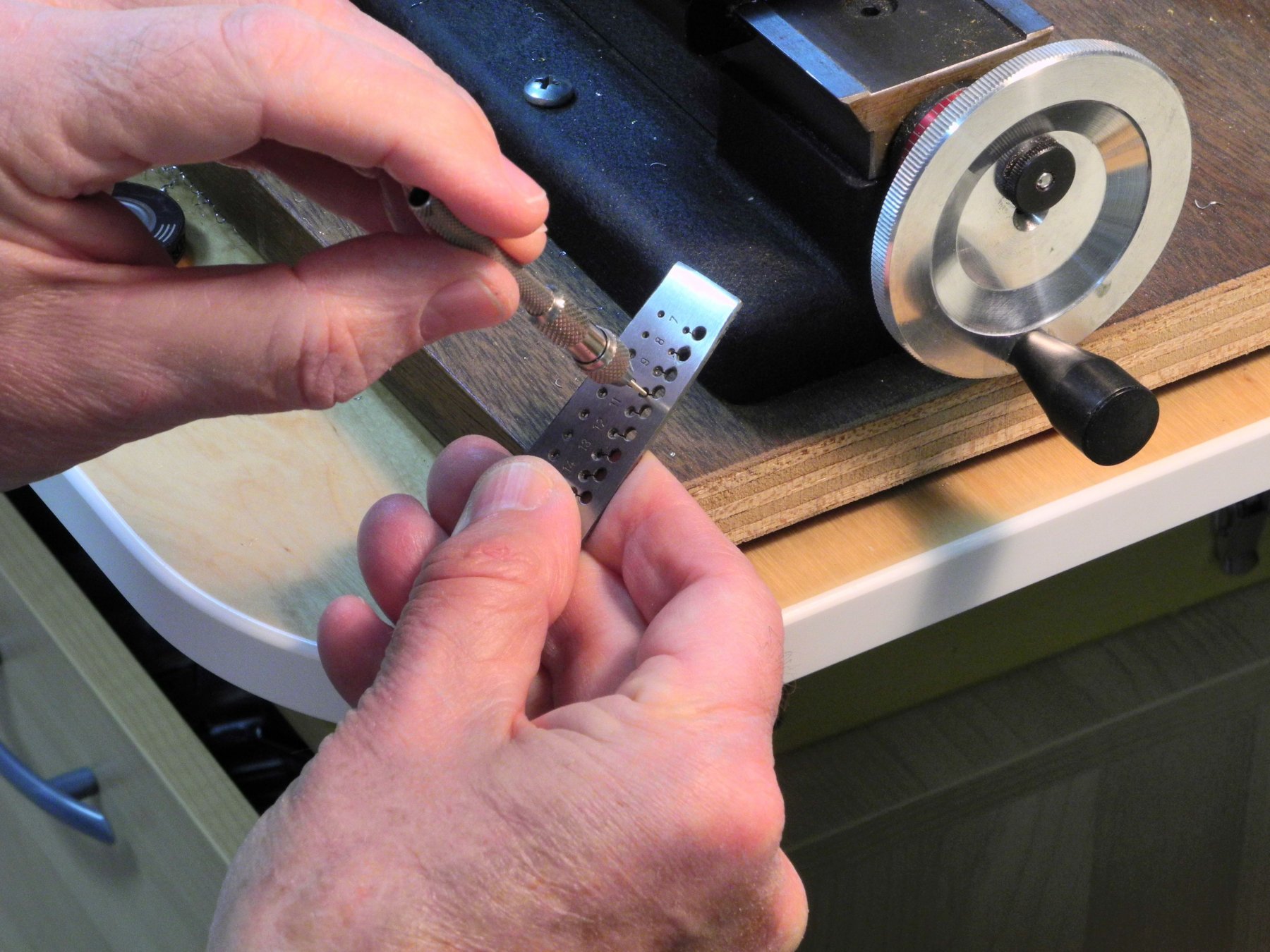
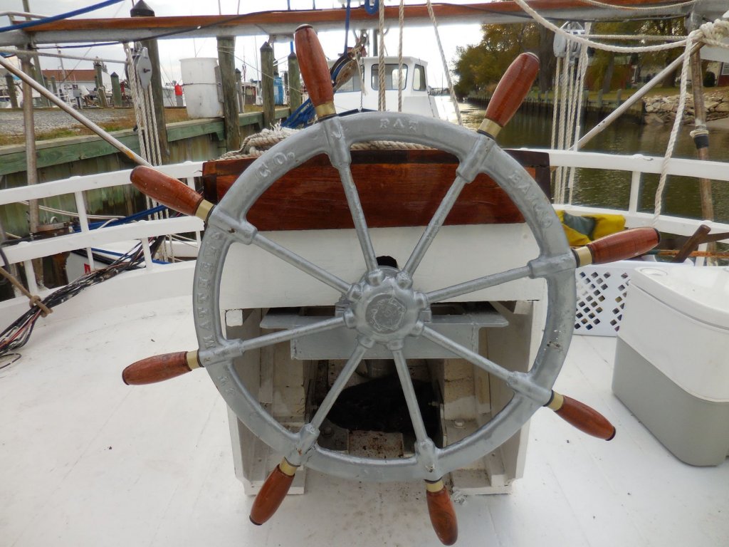
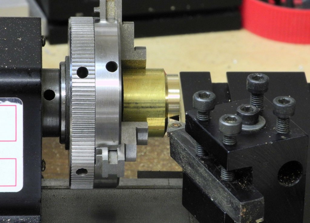
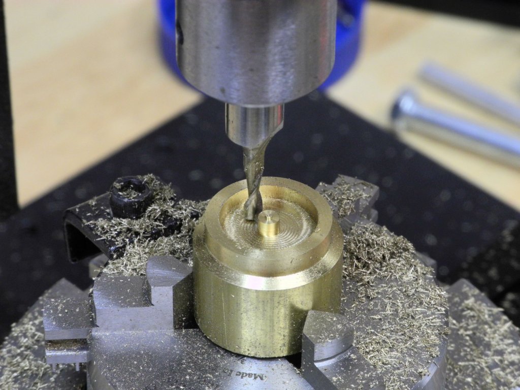
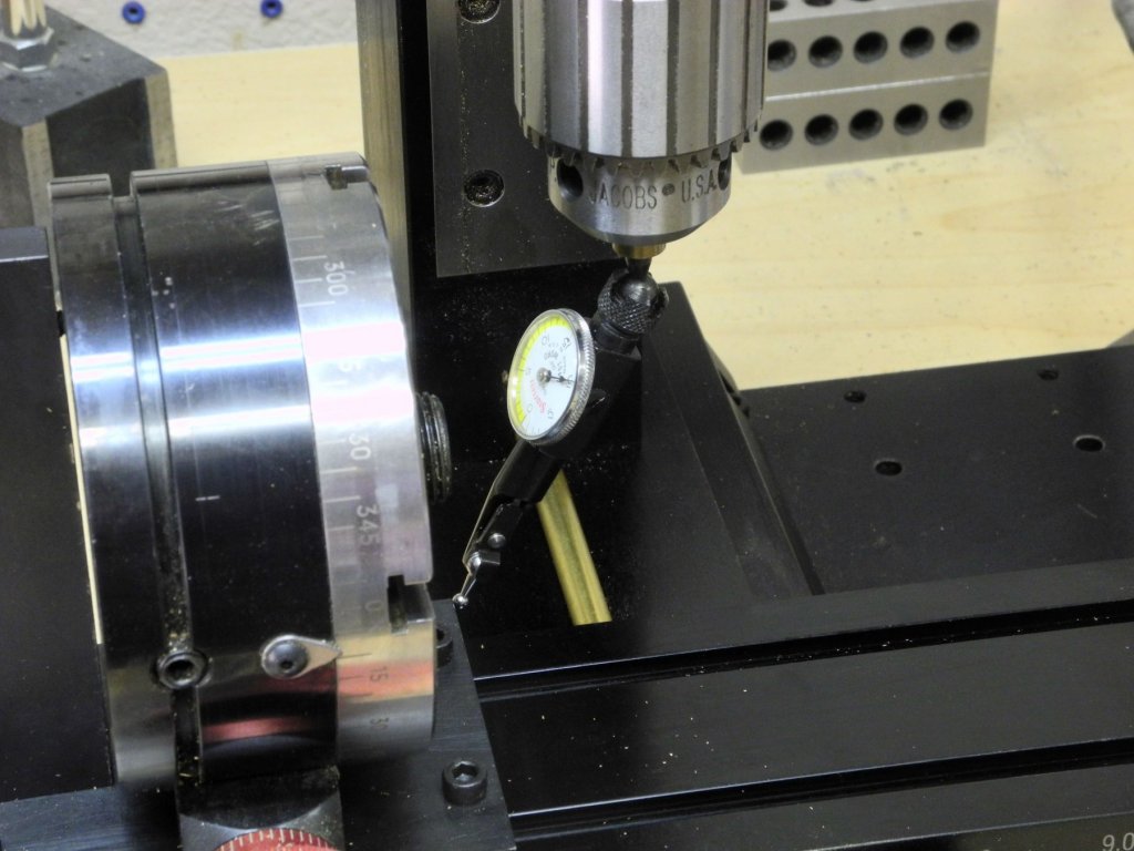
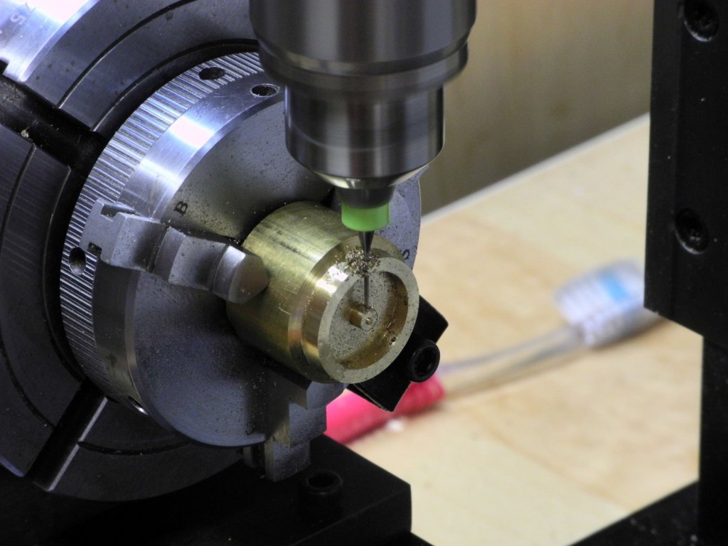
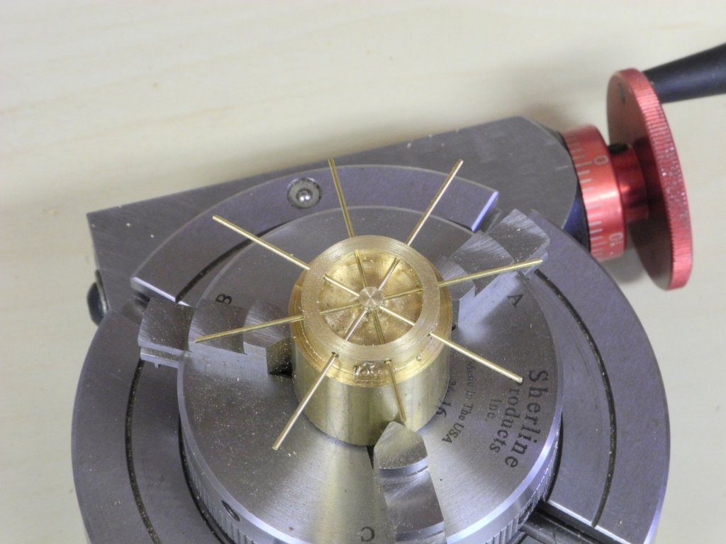
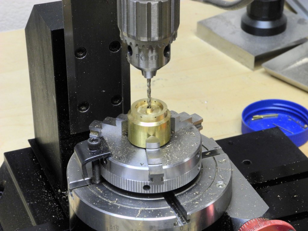
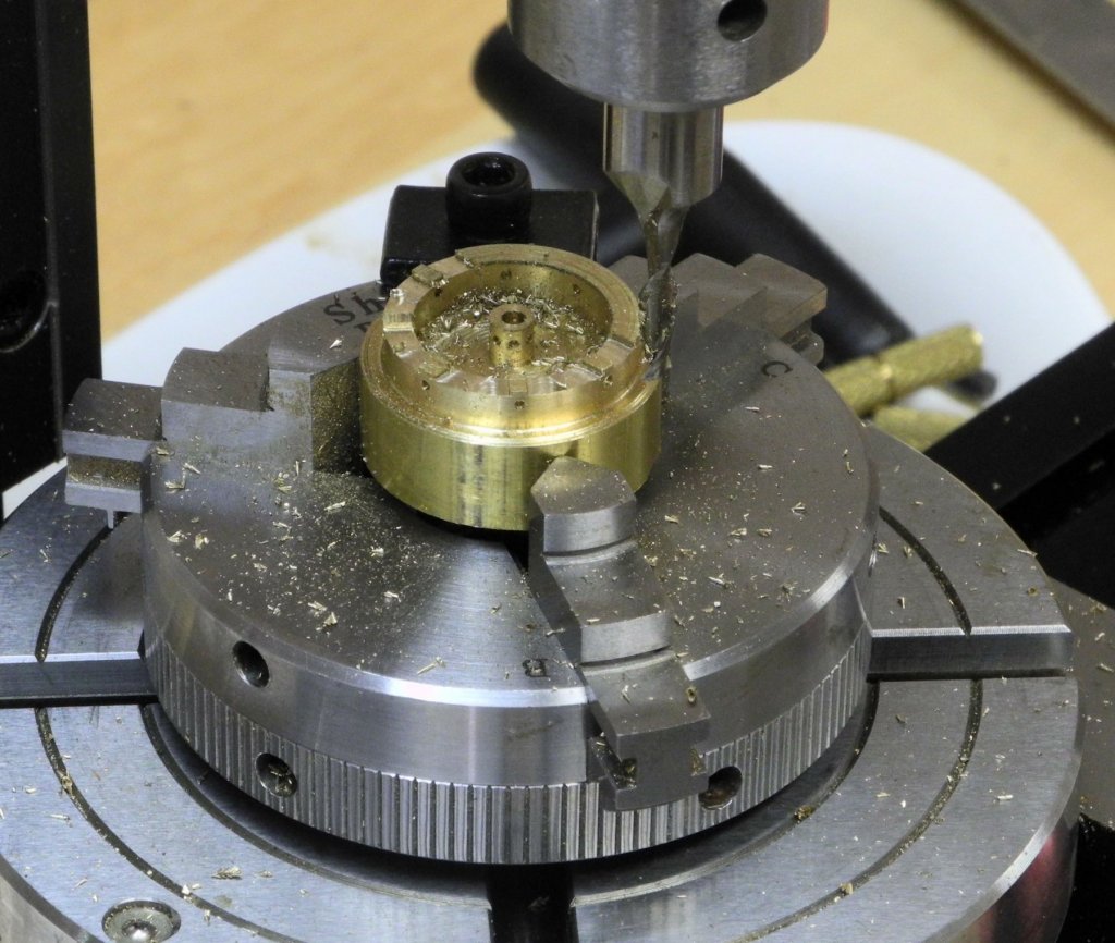
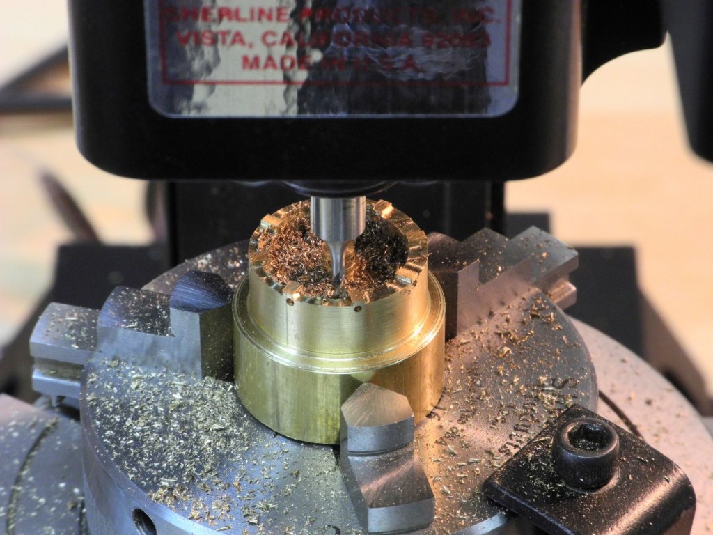
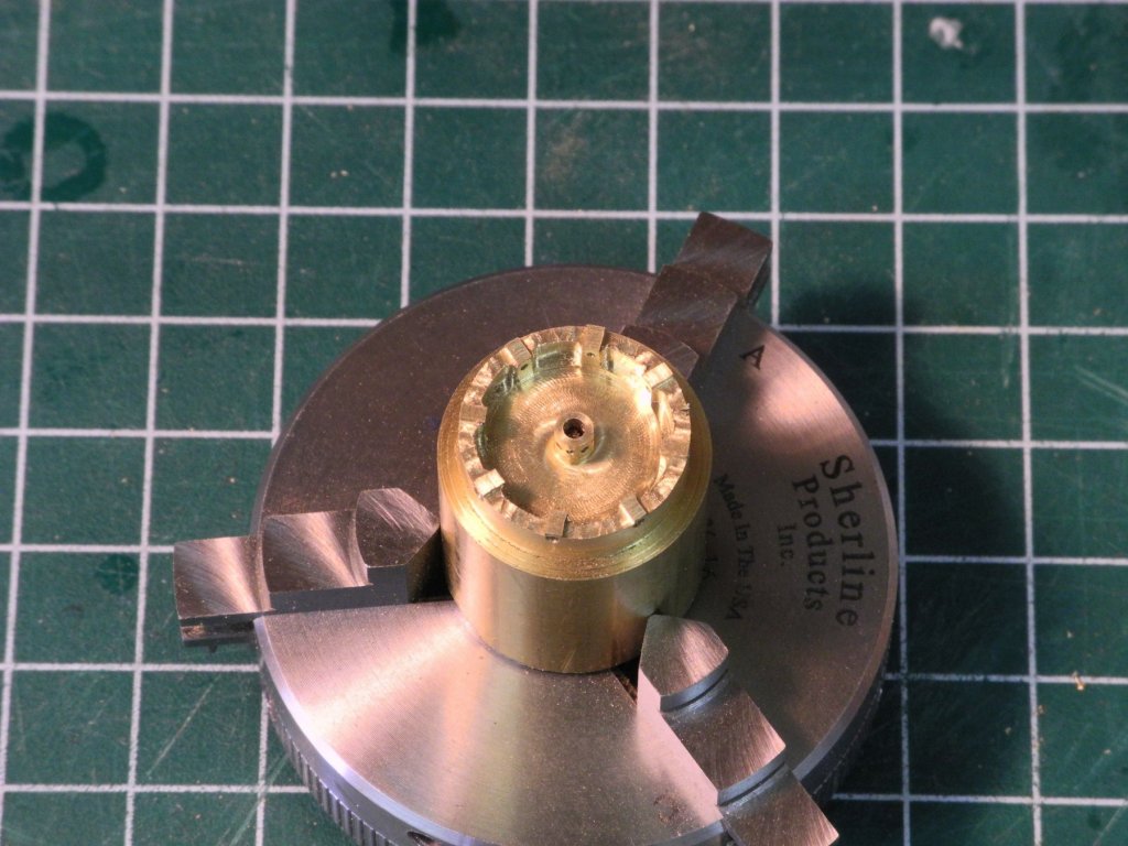
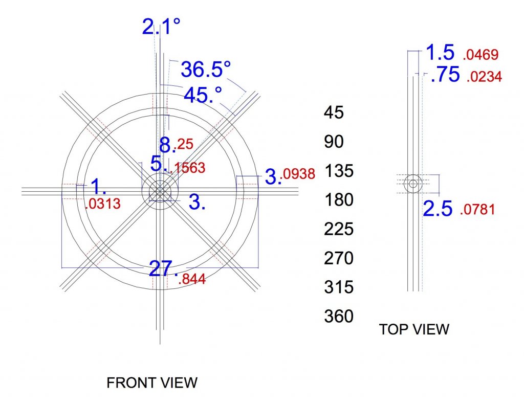
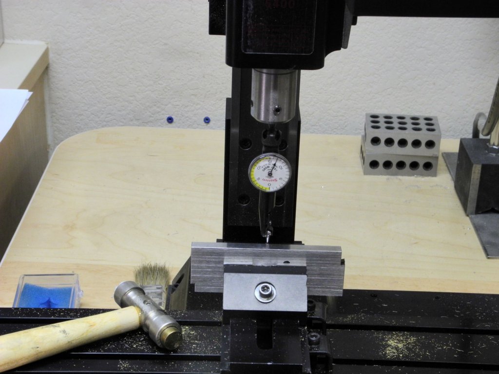
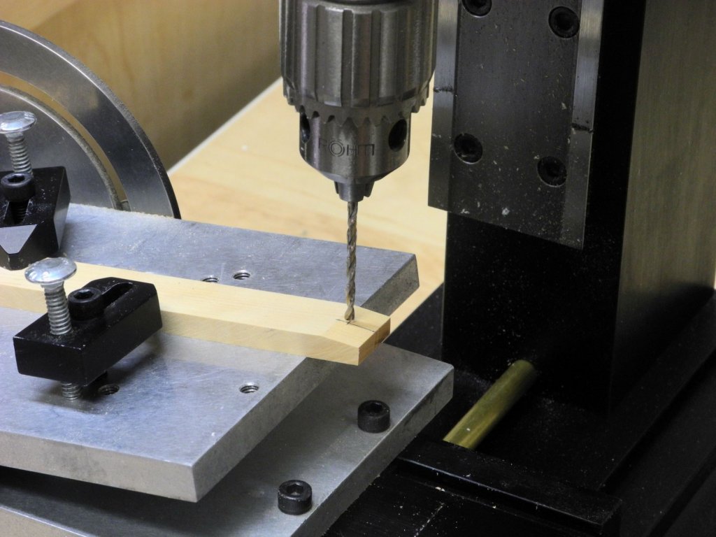
Part 45 – Kathryn’s Wheel Again it has been a while since the last post, but Happy New Year everyone – I hope 2018 brings everyone health and happiness. The last month has been filled with holiday activities that have slowed down the modeling on Kathryn, but there actually is some progress to report. Most of the time has been spent on making Kathryn’s wheel, which turned out to be a quite complicated milling job. Kathryn’s wheel, shown in the following photos, is all metal (except for the wooden hand grips). The rim of the wheel is fairly thin, exceeding the diameter of the spokes by only a small amount. There are bumps on the rim whenre the spokes pass through – I’ll call them ‘spoke seats’. The spokes are held on the hub by nuts. The diameter of the wheel was measured from the HAER drawings. The photo was imported into TurboCad, and the diameter of the wheel was used to scale the photo so that the other wheel measurements could be determined. The following drawing shows those dimensions (blue used for actual dimensions, while red was used for the scaled dimensions for the model). A 1-inch diameter brass rod was used to mill the wheel rim and hub. After mounting the rod in the 3-jaw chuck, the first step was to face the end of the rod and to reduce the end of the rod to the final diameter. The chuck and rod combination was transferred to the rotary table on the milling machine, and the rim and hub were milled. The next step was drilling the spoke holes. The chuck was removed from the rotary table and the rotary table was installed on the vertical attachment. A dial indicator was used to ensure that the rotary table was squared to the milling machine and that it was perfectly vertical. A center drill was used to start a hole at the spoke location. A carbide drill was then used to drill the spoke hole in the rim. The spokes will be made from 1/32 brass rod, so a #66 drill was used. When the hole was drilled through the rim the drill was fed through until a corresponding hole could be drilled in the hub. The chuck and rotary table combination was removed from the vertical attachment, and 1/32 brass rods were used to check the proper alignment of the holes. The rotary table and chuck were returned to the mill, and the 5/64 center hole for the shaft was drilled. The rim was then milled to a depth of .016 between the spoke seats. As can be seen in the first photo showing the actual wheel, the rim narrows between the spoke seats. This narrowing was performed on the model using a 1/16 end mill held in a collet. After this last operation was completed, the milling of the wheel was finished. The milling sounds relatively simple, but it took the better part of the last month (and six wheels) to get it right. It was a good learning experience – dealing with backlash, centering the mill over a rounded surface, improving the accuracy between steps, etc. Along the way I needed to document the sequence of steps, and a copy of the sequence is attached for anyone interested in seeing the details of the process. Making Kathryn's Wheel.pdf After the milling was completed there was still a lot of work required on the wheel. That’s the subject of the next post. Thanks, everyone!


- 878 replies
-
- 19
-

-
Sure thing Rich - just let me know when. Enjoy the holidays!
- 1,135 replies
-
- 2
-
-
- model shipways
- syren
- (and 2 more)
-
Rich - I'd be happy to help you. I have some woods that I think you'd like, and we could mill them to whatever size you need. Come on down!
- 1,135 replies
-
- 2
-
-
- model shipways
- syren
- (and 2 more)
-
Another version of the 'Third Hand'
Mahuna replied to wefalck's topic in Modeling tools and Workshop Equipment
Excellent ideas and workmanship, Wefalk - thanks for sharing this! -
Hi Ed: The exchange of ideas and methods is one of the things I appreciate about MSW. I'm looking forward to seeing your solution.
- 3,618 replies
-
- 3
-
-
- young america
- clipper
- (and 1 more)
-
Thanks Peter. I think the approach will work. It will be a while before I need the actual turnbuckles, so I'm working on other things now.
-
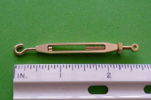
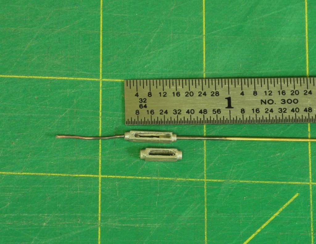
Hi Peter. Yes, your illustration is what I plan, except that instead of a small washer there is a plug soldered on the end of the swivel to secure it inside the turnbuckle. Jerry - thanks for those links. It appears that the turnbuckles from Model Yacht Fittings are also made with a swivel instead of LH thread (the hook end). This photo appears to be their smallest size, which would be too big on the Kathryn.
-
Hi Mark: I do have a set of jewelers taps and dies, so threading is really not an issue. The problem is that I only have right-hand threading capability and for the turnbuckles to actually work one end needs to be left-hand thread. This is the reason why I'm planning on using a swivel at that end. This will allow me to tension the shrouds using the turnbuckles. Since the shrouds will be made of wire (Kathryn's shrouds are steel wire) I'm a little concerned about adjusting the tension without using the turnbuckles.
-
Very nice turnbuckle, John - thanks for sharing it. I just took a look at your Buyboat - very nice! You have a real nice website as well - I plan to spend some time looking at your other models.
-
Thanks for the link, Druxey. You're right - they are quite expensive. I'll stay with the swivel idea.
-
The smallest LH taps I've been able to find are 0-80, but at 3/64" I think that's too big for the turnbuckles. The swivel seems to work OK if I can figure out a way to add a ring at the end after the rod has been inserted into the turnbuckle.
-
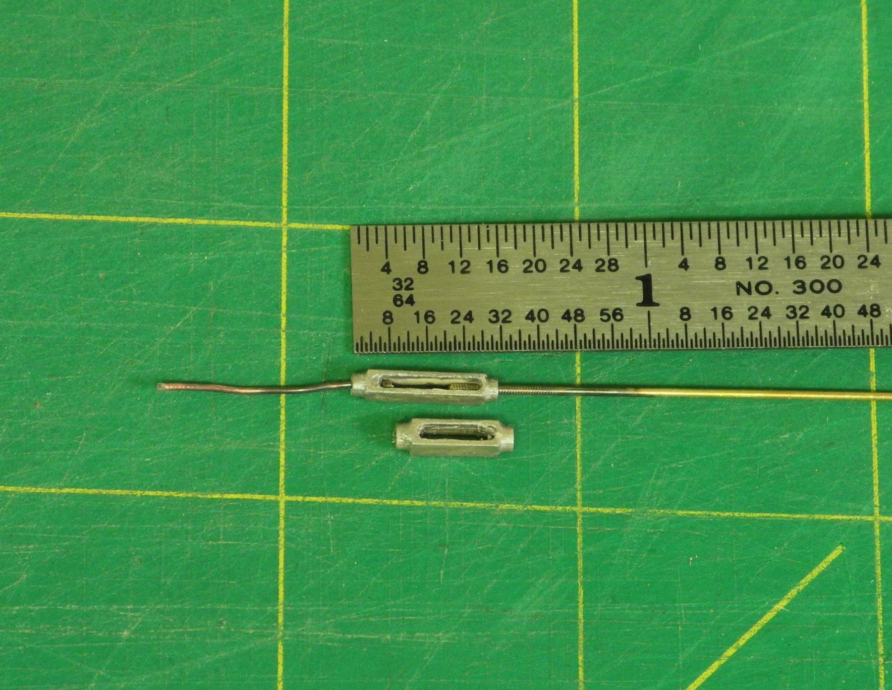
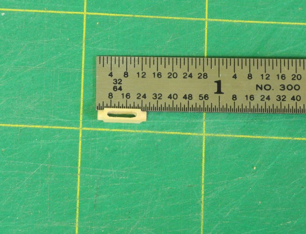
Part 44 – Turnbuckles There hasn’t been too much progress on Kathryn lately. Holidays, other activities, and some inertia have kept me from getting much modeling done. There is a lot of planning and experimenting needed before moving on to the next stages. One key item is turnbuckles. Since the shrouds will be made from wire, some working turnbuckles need to be created to allow tensioning the shrouds. The turnbuckle sizes require the use of jewelers taps and dies for threading. Since these tools only come in right-hand thread, the end that would normally have a left-hand thread will have a swivel arrangement instead. I started by making the turnbuckle body from 3/32" square brass bar stock. After breaking some taps, drill bits, and a fairly expensive small end mill, I decided to make the turnbuckle body from wood. The first turnbuckle I made is 3/8” long – 1 foot at 1:32. A 3/32” square piece of castello 3/8” long was held in the lathe using a 4-jaw chuck. The first operation was facing the end of the piece. A small centering drill bit was then used to drill a pilot hole. A #69 drill bit was then drilled into the end of the wood. This hole would later be threaded to take a 1/32” threaded brass rod. The end of the turnbuckle body was then rounded to a depth of .050” These operations were repeated at the other end of the turnbuckle body, with the final hole drilled with a #72 drill. This would provide clearance for a smooth (unthreaded) piece of copper wire that will act as a swivel. A small knob on the end of the wire will prevent the wire from pulling out of the turnbuckle. The slot in the turnbuckle body was cut with a .045” cylindrical carbide cutter on the milling machine. Prior to cutting this slot the milling vise was indicated to ensure that the slot was properly cut. Any slight variation off center would be very noticeable at this scale. The end of the turnbuckle that was sized for the 1/32” brass bar was threaded. A piece of 1/32” round brass bar was also threaded. The following photo shows the finished turnbuckle body, still unpainted. The turnbuckle body was painted using a steel color ModelMaster acrylic paint. The final turnbuckle appeared too thick when compared to photos of the real Kathryn, so the process was repeated using 5/64 wood stock. The following photo shows the comparison of the two turnbuckles. These turnbuckles are ‘prototypes’ for the final turnbuckles, so I didn’t spend much time in the painting step. Prototypes will also be developed for the various shackles, clevis ends for some of the turnbuckles, and other small items. There is also quite a bit of planning required for the stages still remaining, so progress will be slow for a while yet. Thanks everyone!


- 878 replies
-
- 17
-
-
Excellent block-making tutorial, Ed - thanks! I imagine a small end mill could be used instead of the scraper to make the strapping groove.
- 3,618 replies
-
- 3
-
-
- young america
- clipper
- (and 1 more)
-
Looks great at this stage, Patrick. I'm sure she'll be gorgeous when you're finally finished.
-
Thanks Carl. The soldering device is actually a resistance soldering unit. Works great for the size of components we deal with in modeling. I decided to use CA to secure the sleeve since there wouldn't be any stress on it.
-
Thanks Patrick. The work is starting to get a little more complex, so I'll be going slowly.
-
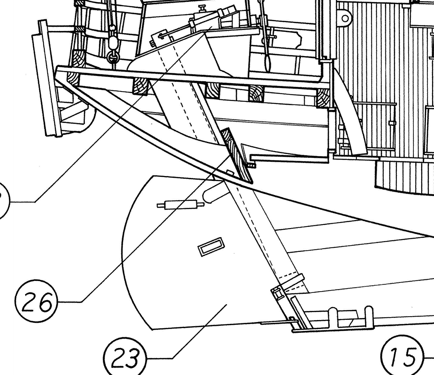
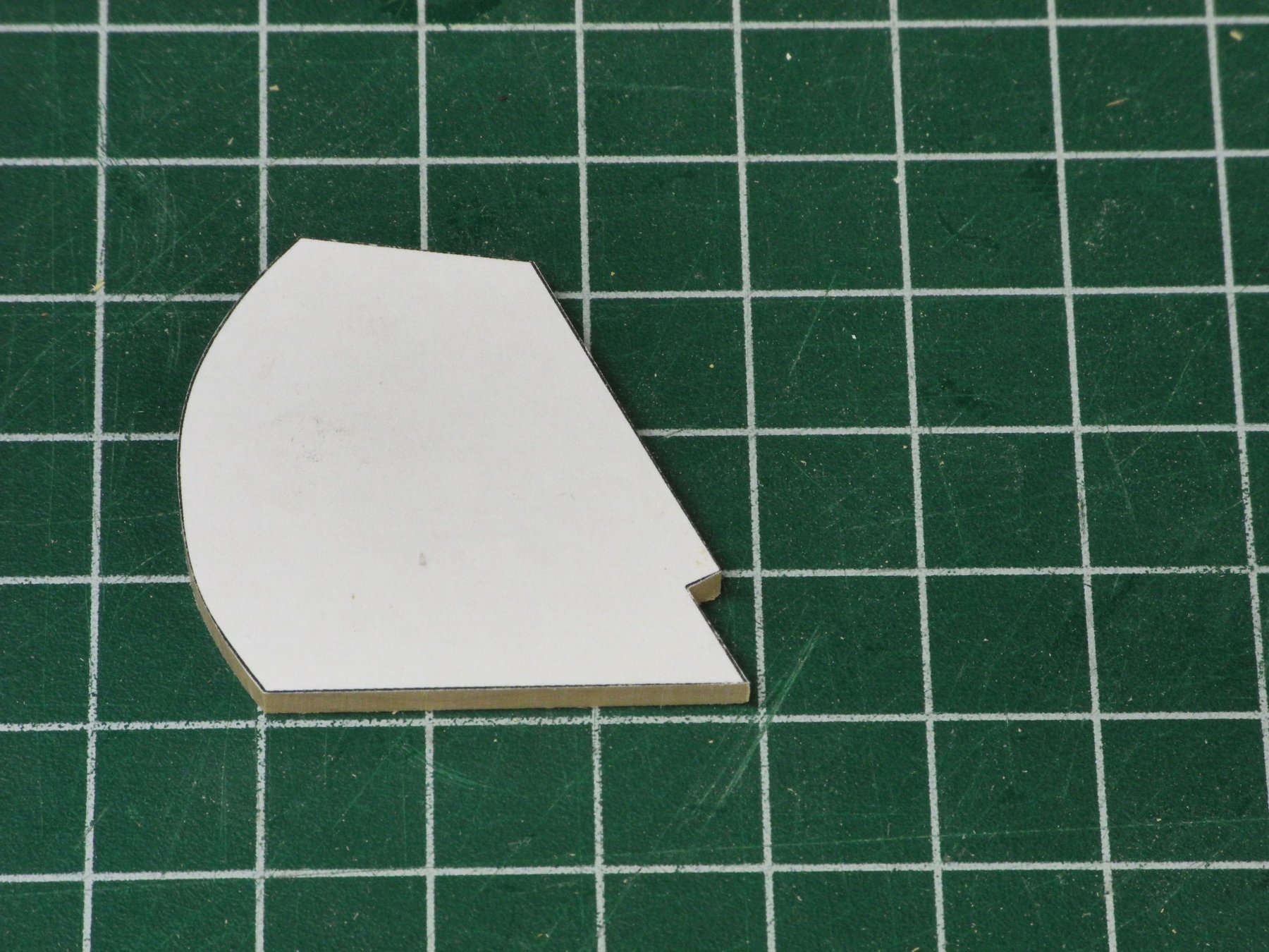
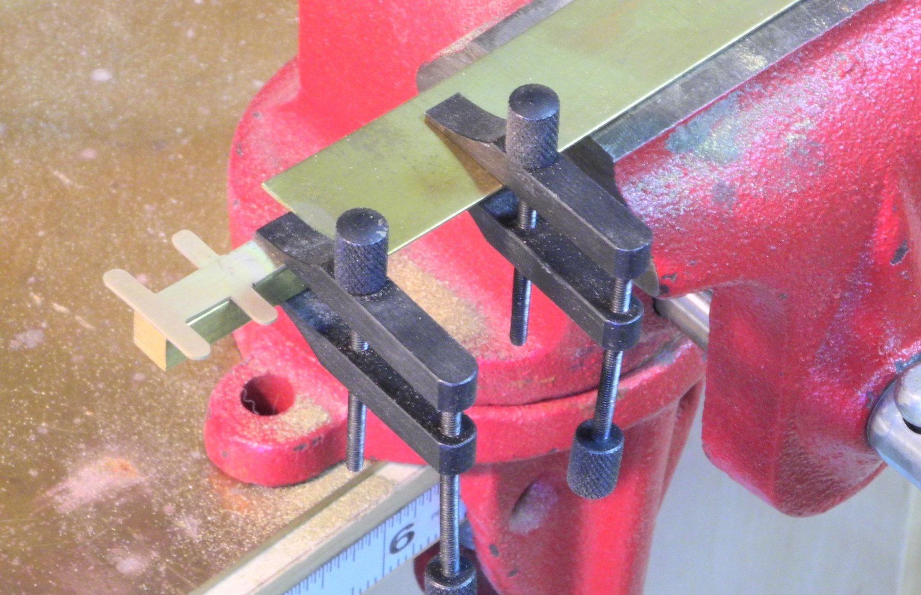
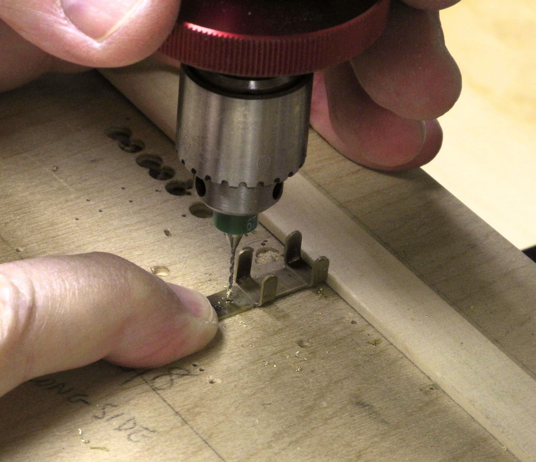
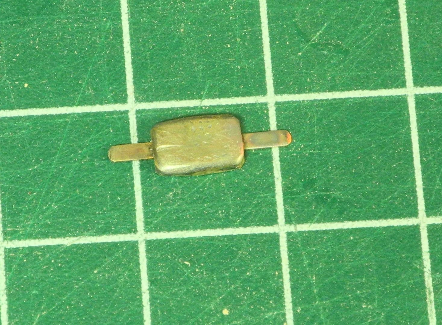
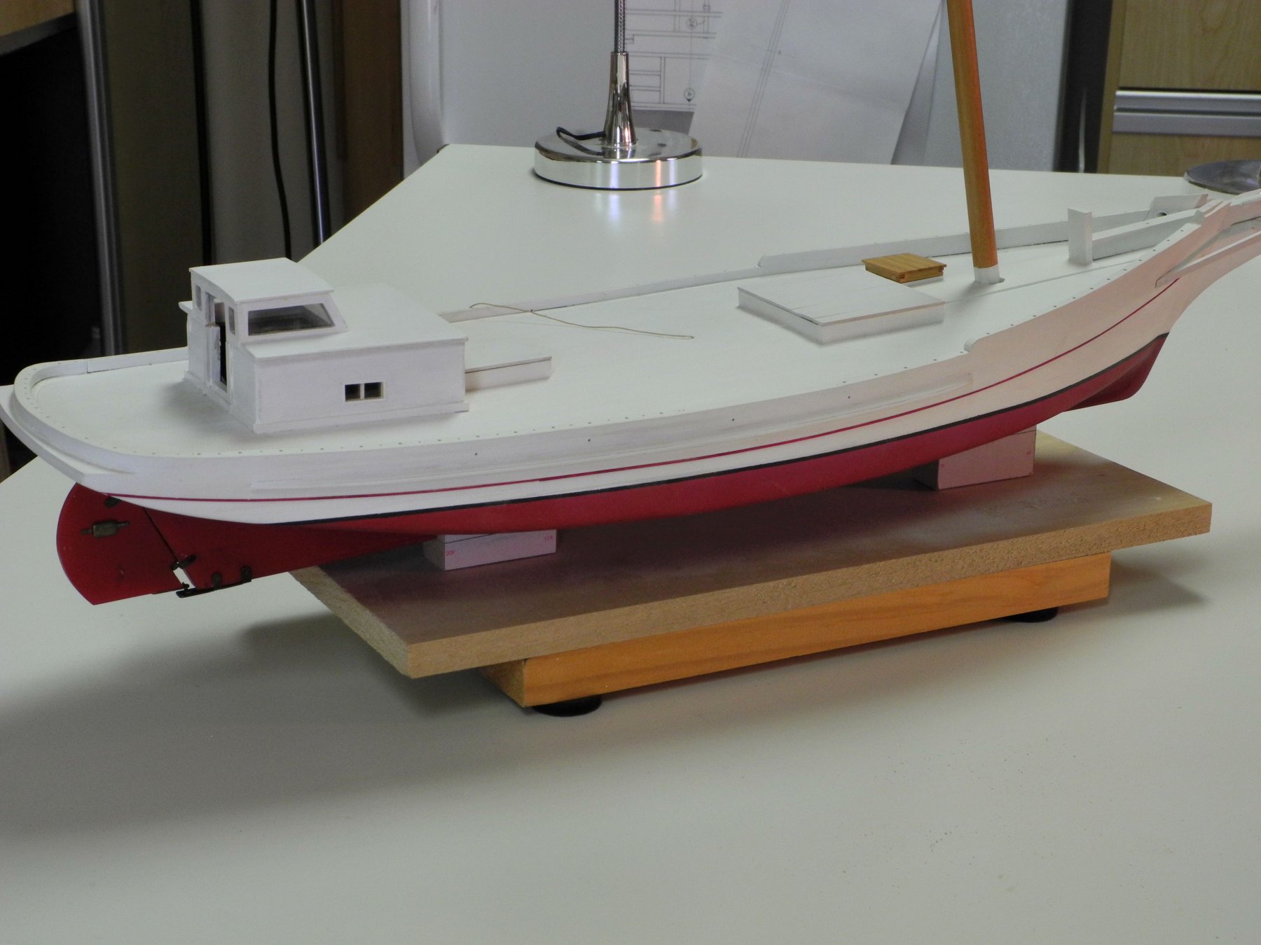
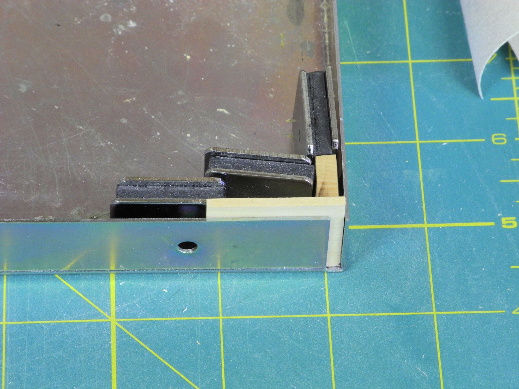
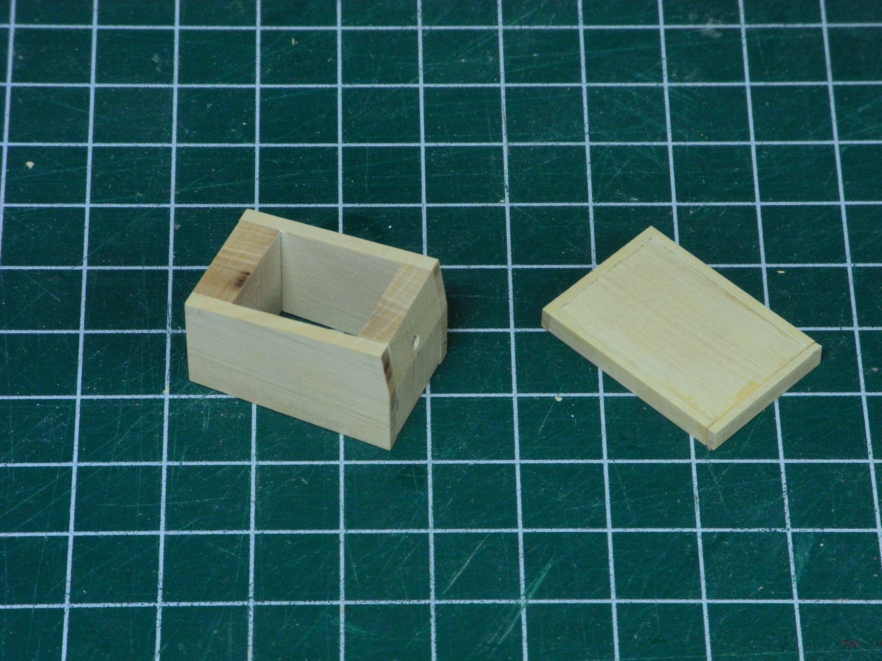
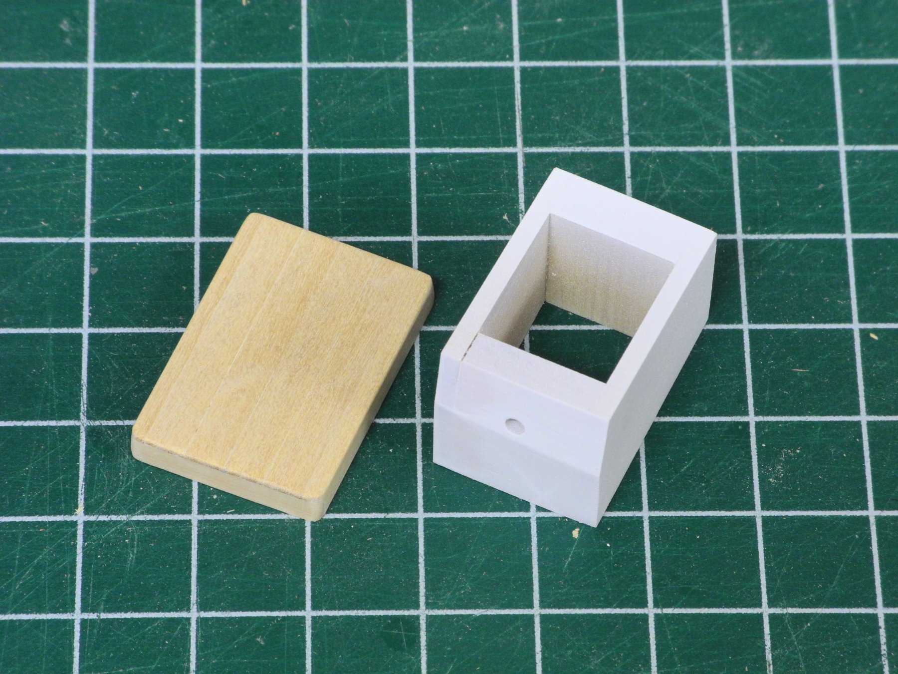
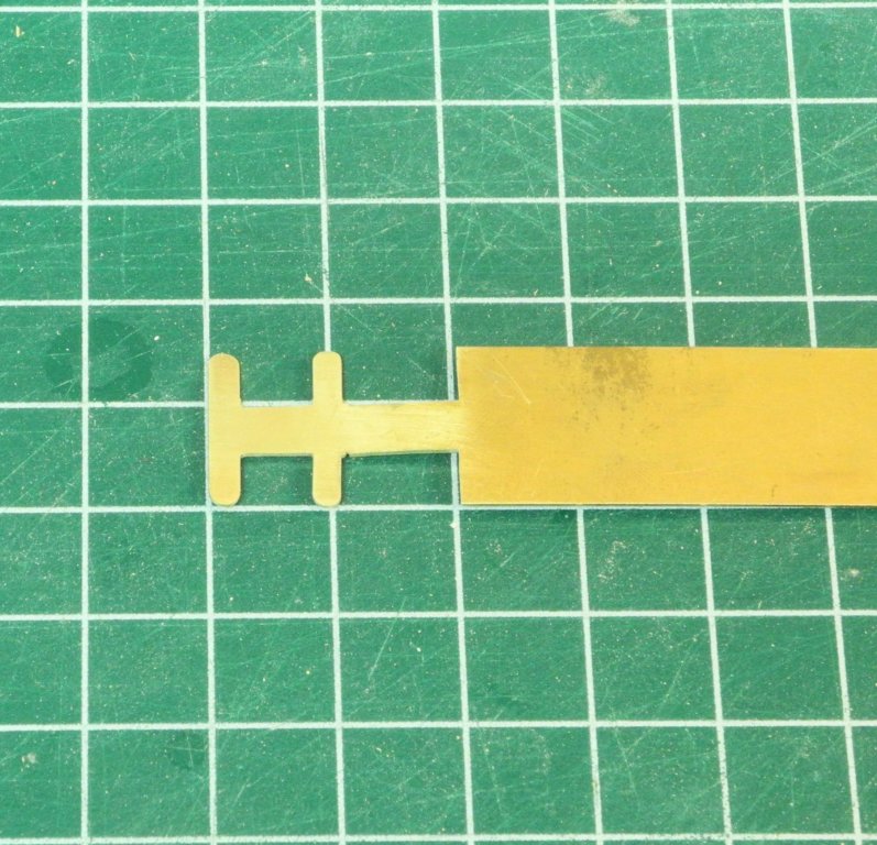
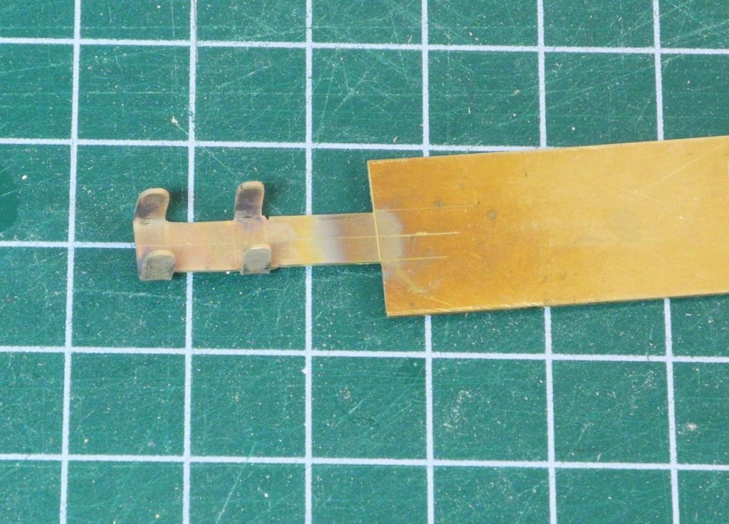
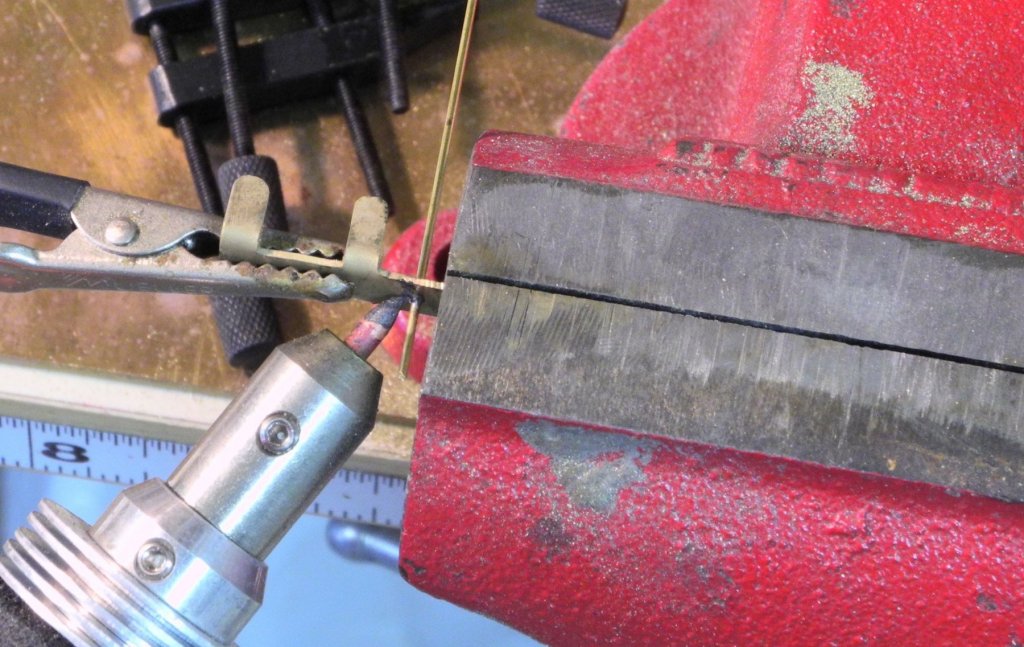
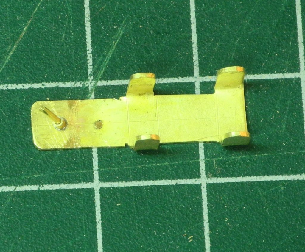
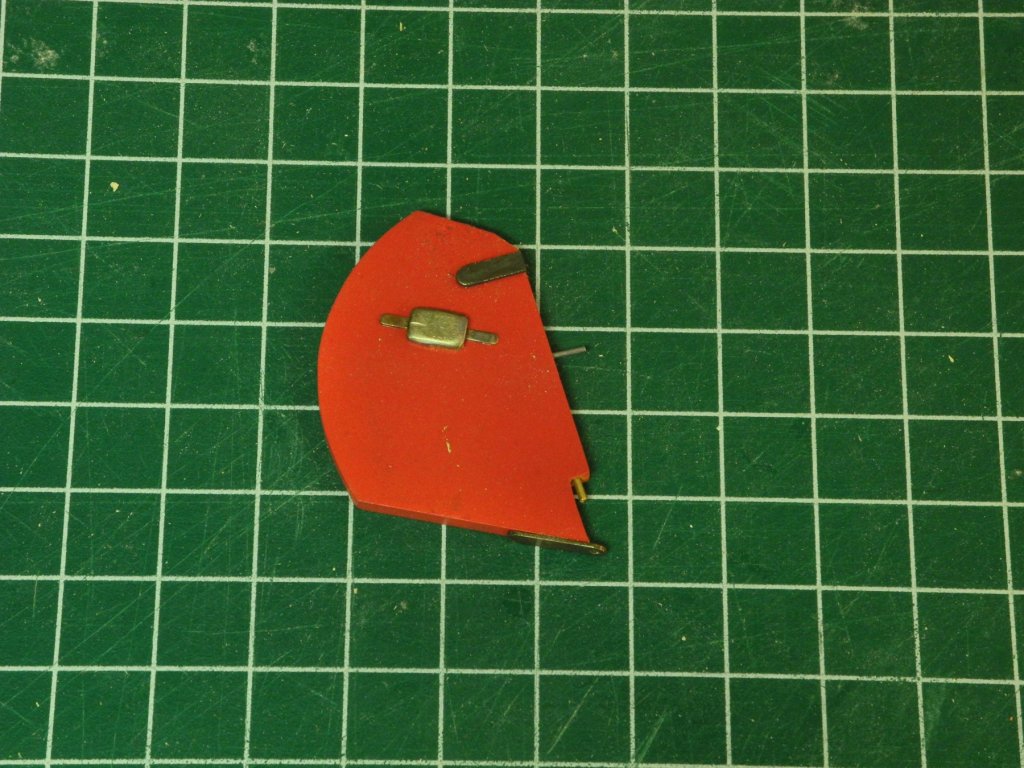
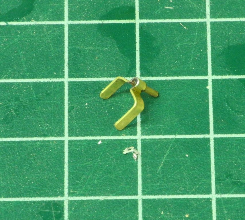
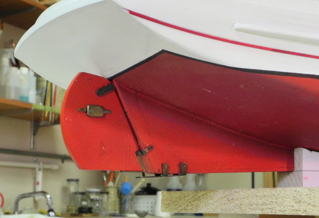
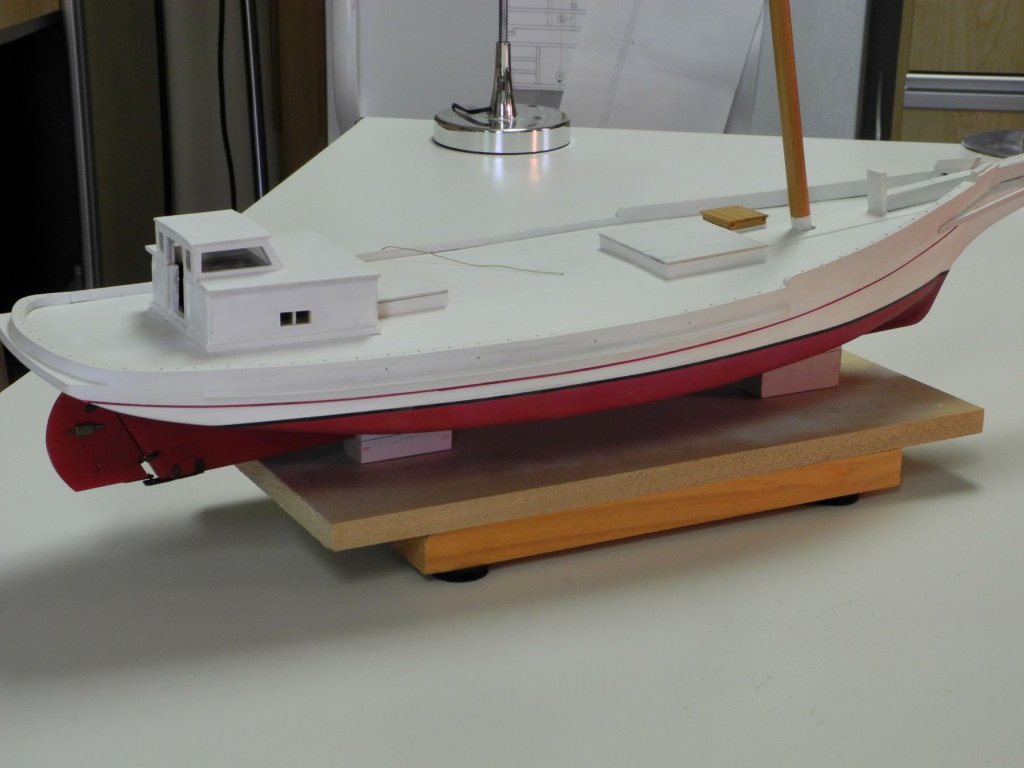
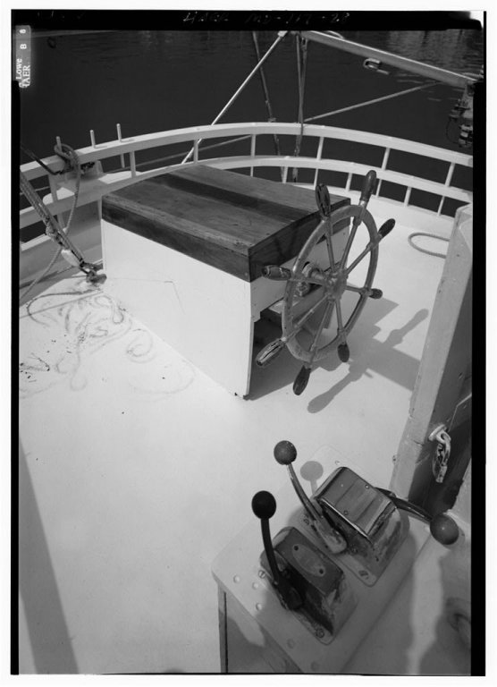
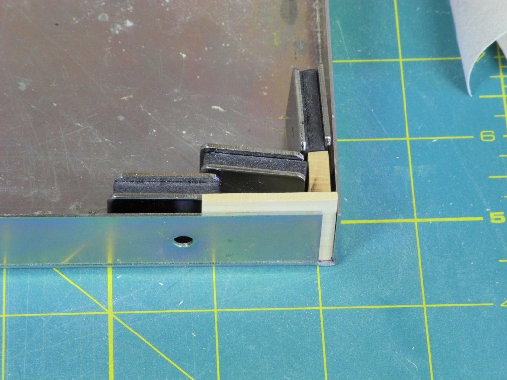
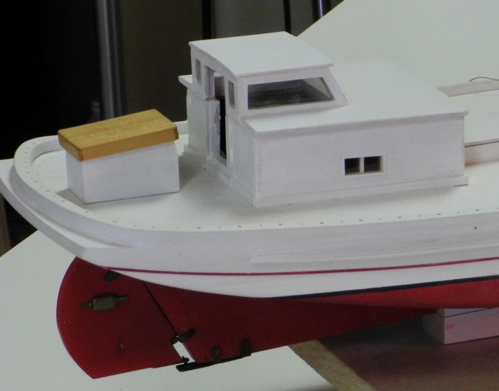
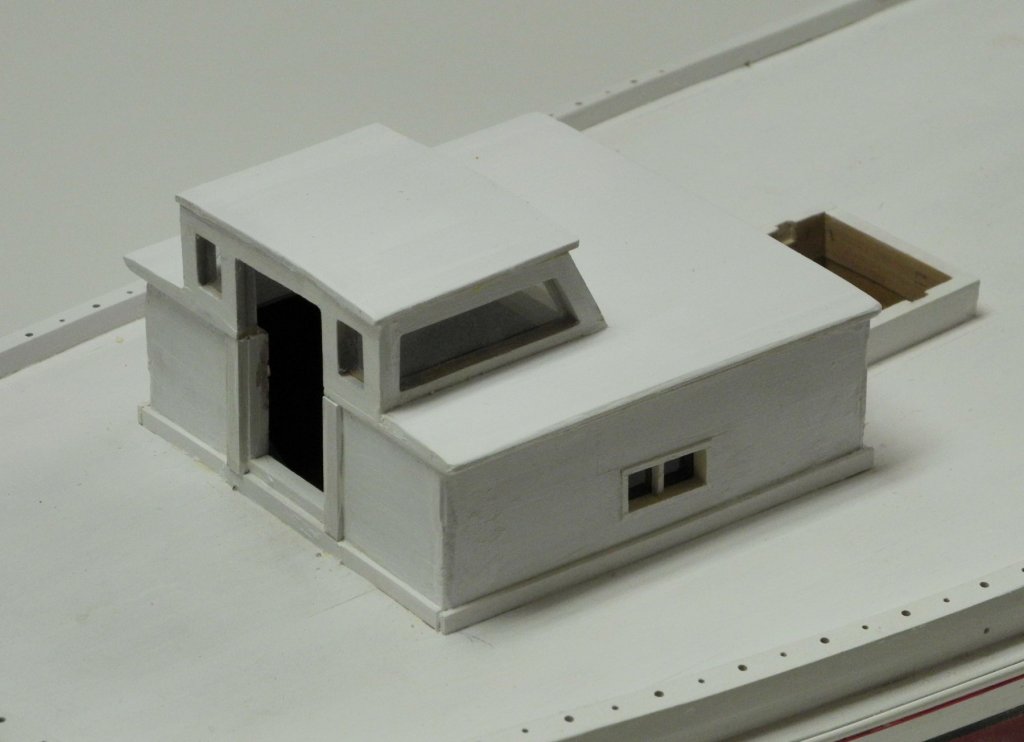
Part 43 – Rudder Kathryn has a stainless steel inboard rudder today, and this rudder was already in place during the time of the HAER survey. The construction of the rudder and its hardware is different from what is normally seen with traditional rudders, as can be seen from the following HAER drawing. The rudder rests on a bracket attached to the bottom of the keel. Just above that bracket there appears to be a fairly typical gudgeon, and at the top of the rudder there appears to be a bracket that is attached to the rudder post. Aft of that bracket is an unusual configuration on the face of the rudder. I’ve learned that this is actually a ‘sacrificial anode’, generally called a ‘zinc’. From Chemistry LibreTexts: When metal surfaces come into contact with electrolytes, they undergo an electrochemical reaction known as corrosion. Metal in seawater is one such example with the iron metal coming into contact with electrolytes. Under normal circumstances, the iron metal would react with the electrolytes and begin to corrode, growing weaker in structure and disintegrating. The addition of zinc, a sacrificial anode, would prevent the iron metal from "corroding". According to the table of Standard Reduction Potentials, the standard reduction potential of zinc is about -0.76 volts. The standard reduction potential of iron is about -0.44 volts. This difference in reduction potential means that Zinc would oxidize much faster than iron would. In fact, zinc would oxidize completely before iron would begin to react. Although the actual rudder is stainless steel, the rudder for the model is made from wood. The bottom bracket was made by cutting the shape from a flat piece of brass bar stock, and then finishing the shape using files. The bracket was then annealed to allow bending, and was bent around a piece of ¼” square brass bar. A vertical post on the bracket fits into a matching piece at the bottom of the rudder. A hole for this post was drilled using the Sensitive Drilling Attachment. The post (a 1/32” rod) was then soldered to the bracket. And a sleeve made from 3/64” tubing was then attached to the post using CA glue. This sleeve serves as a ‘stop’ to keep the rudder from bottoming out on the bracket. The ‘zinc’ was made from brass and then was finished with Flemish Black to impart a silver color. In actual practice the ‘zinc’ would not have been coated. The gudgeon was fabricated from a 1/8 x .025 brass strip, and the pin was soldered into place. The finished rudder was installed. The steering gear is housed in a wooden box aft of the cabin. A thick piece of stock was used for the ends of the steering box to allow a secure installation of the steering wheel. Since the wheel is set at a slight angle, the top of the forward face was cut to that angle, and the hole for the steering wheel’s shaft was drilled perpendicular to that face using the Tilting Angle table on the mill. The sides and ends of the steering box were glued up using the magnetic squaring jig. The top of the steering box was made to fit. The top was then planked and the body of the box was painted. In the following photo the finished box was set in place but not permanently attached. This will wait until the ship’s wheel has been fabricated to ensure that there is enough clearance for the cabin doors. Most, if not all, of the wood construction is now completed. There is quite a bit of complicated (for me) metalwork ahead, and I will need to spend some time planning the next steps. Thanks everyone for following, and for the ‘Likes’ and comments.


- 878 replies
-
- 18
-
-
The detail on YA continues to amaze me, Ed. Excellent work!
- 3,618 replies
-
- 5
-
-
- young america
- clipper
- (and 1 more)
-
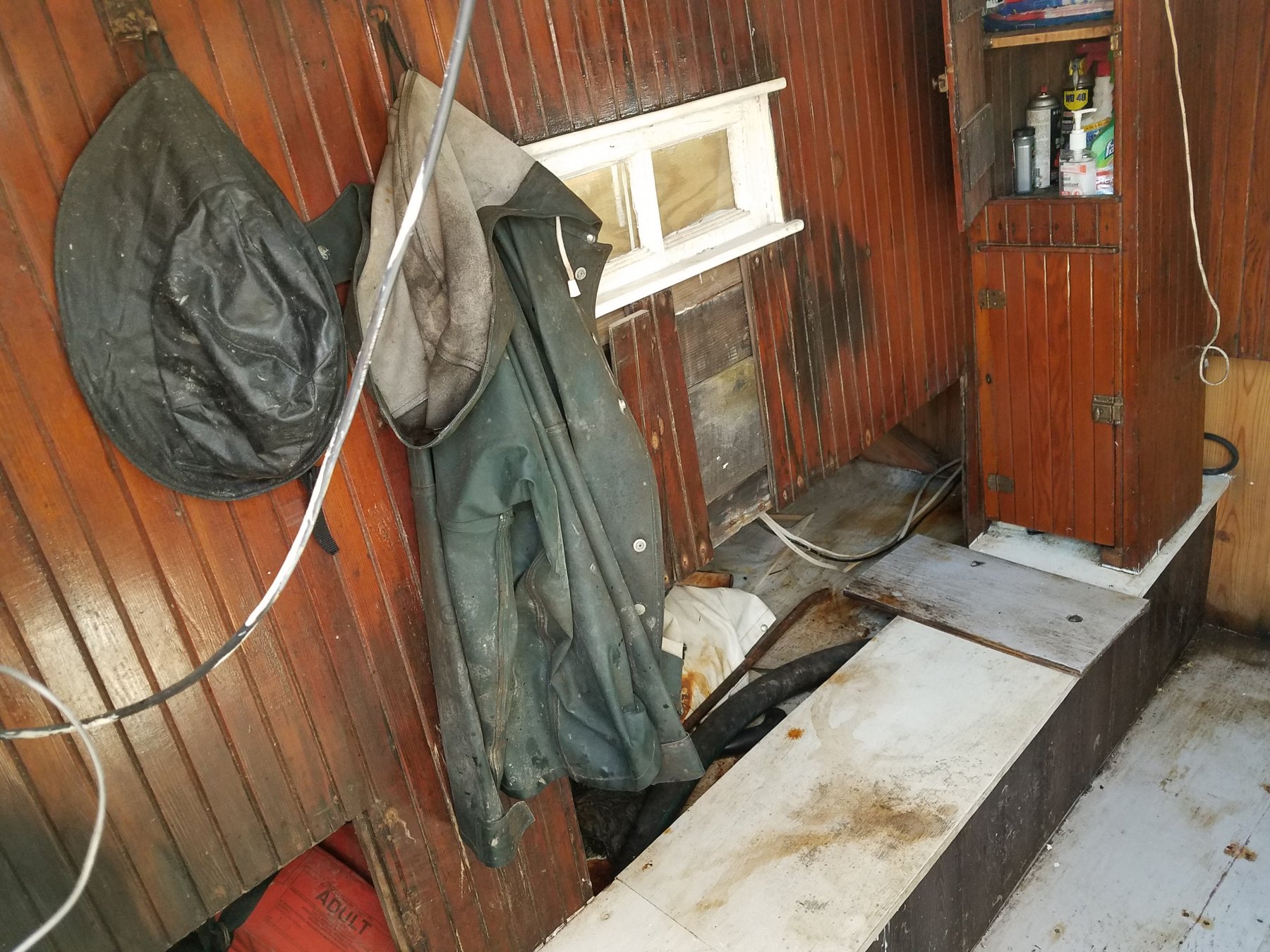
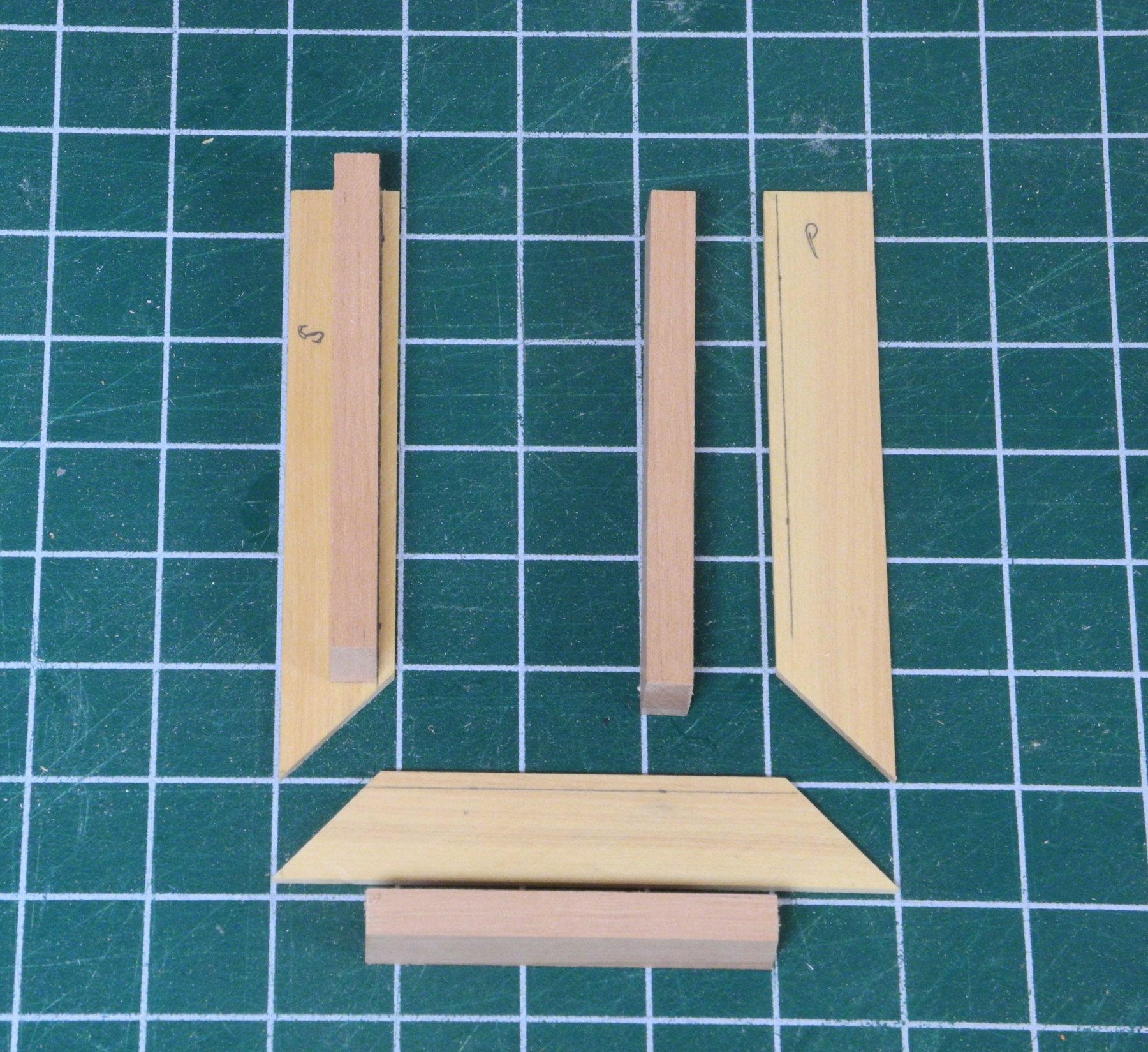
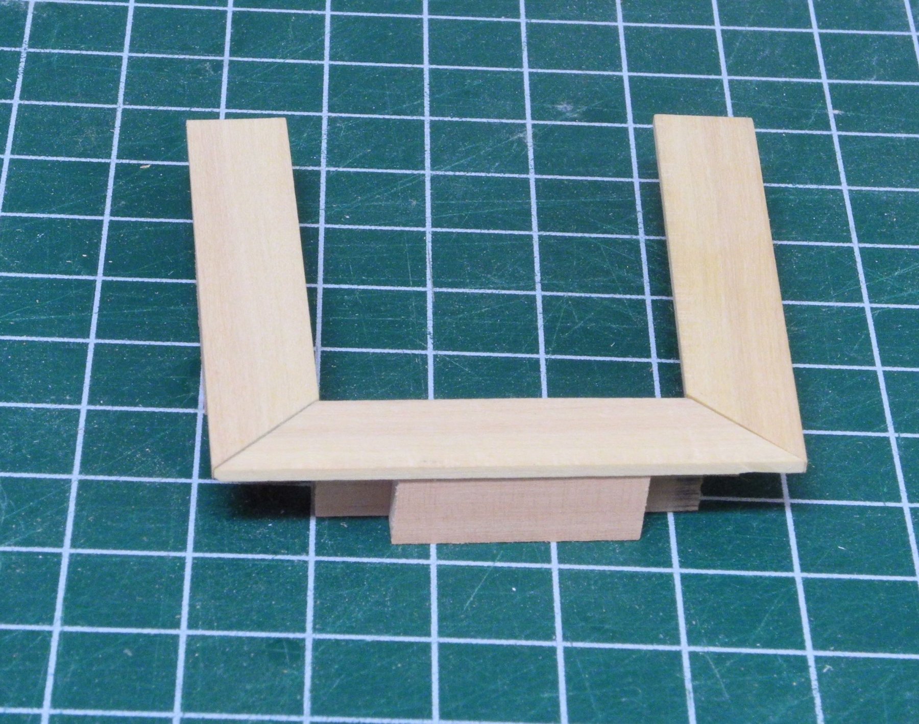
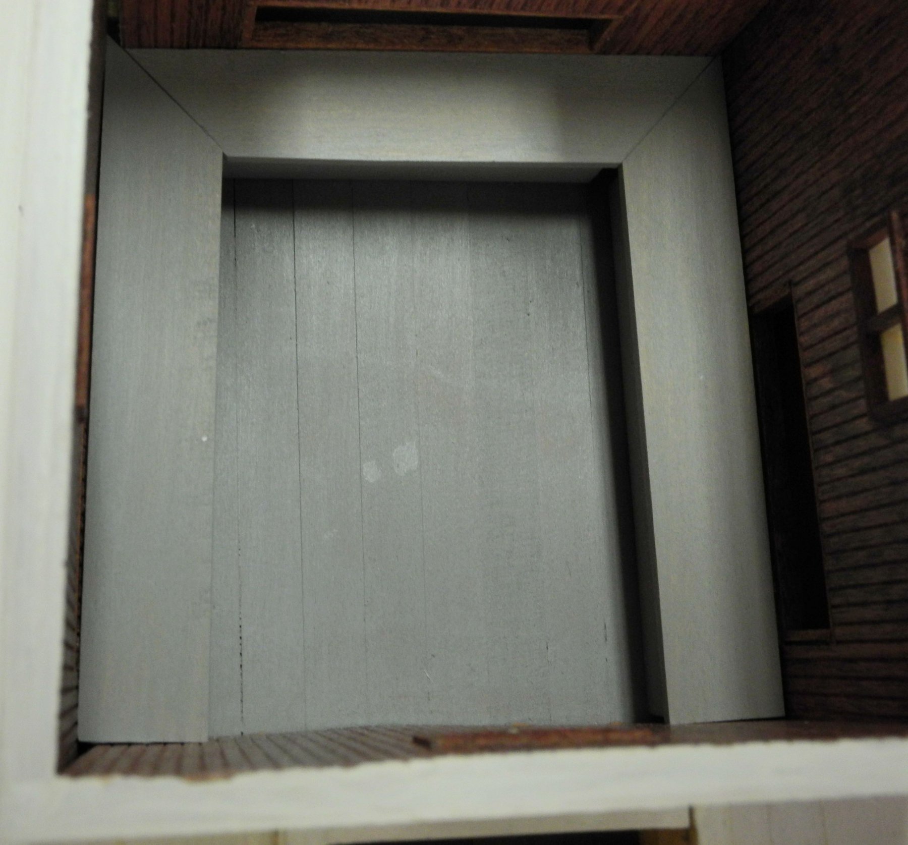
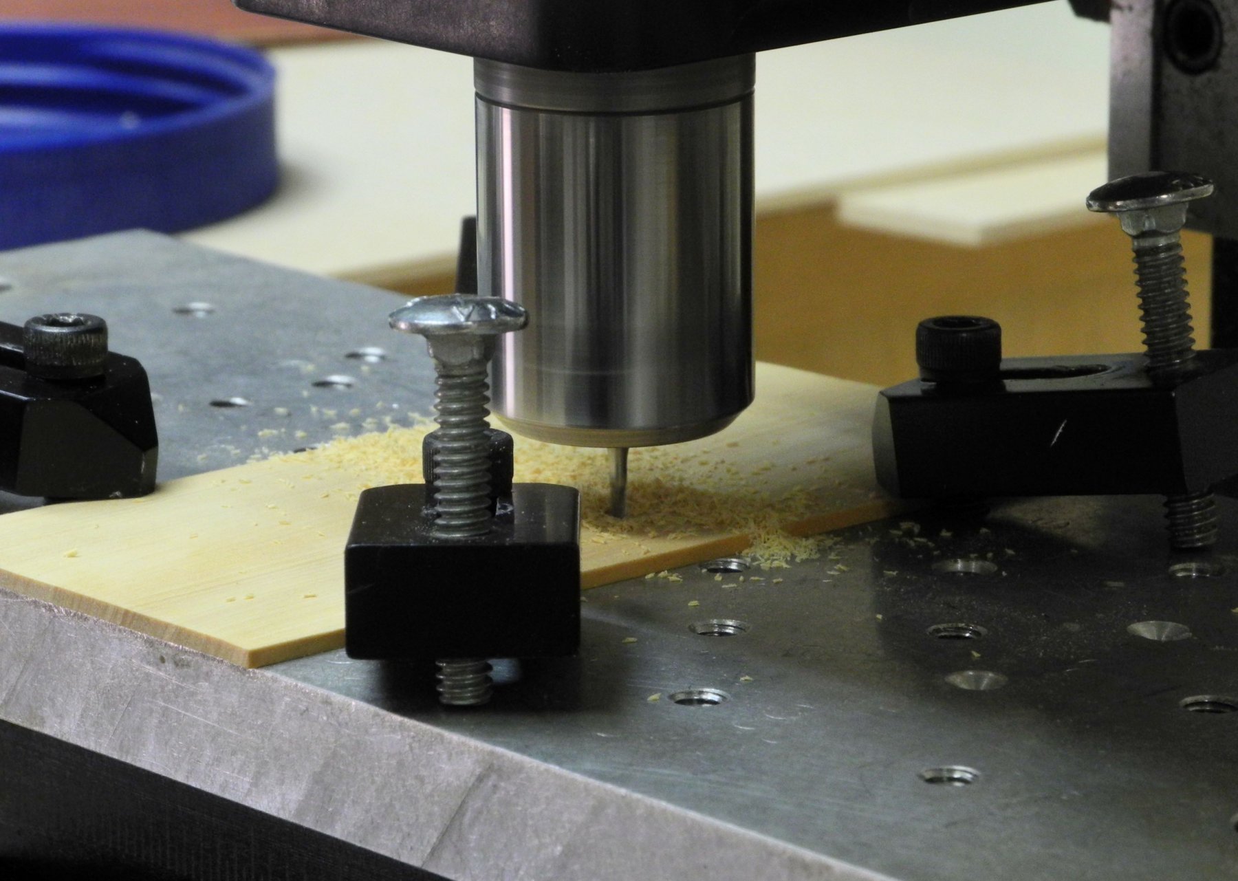
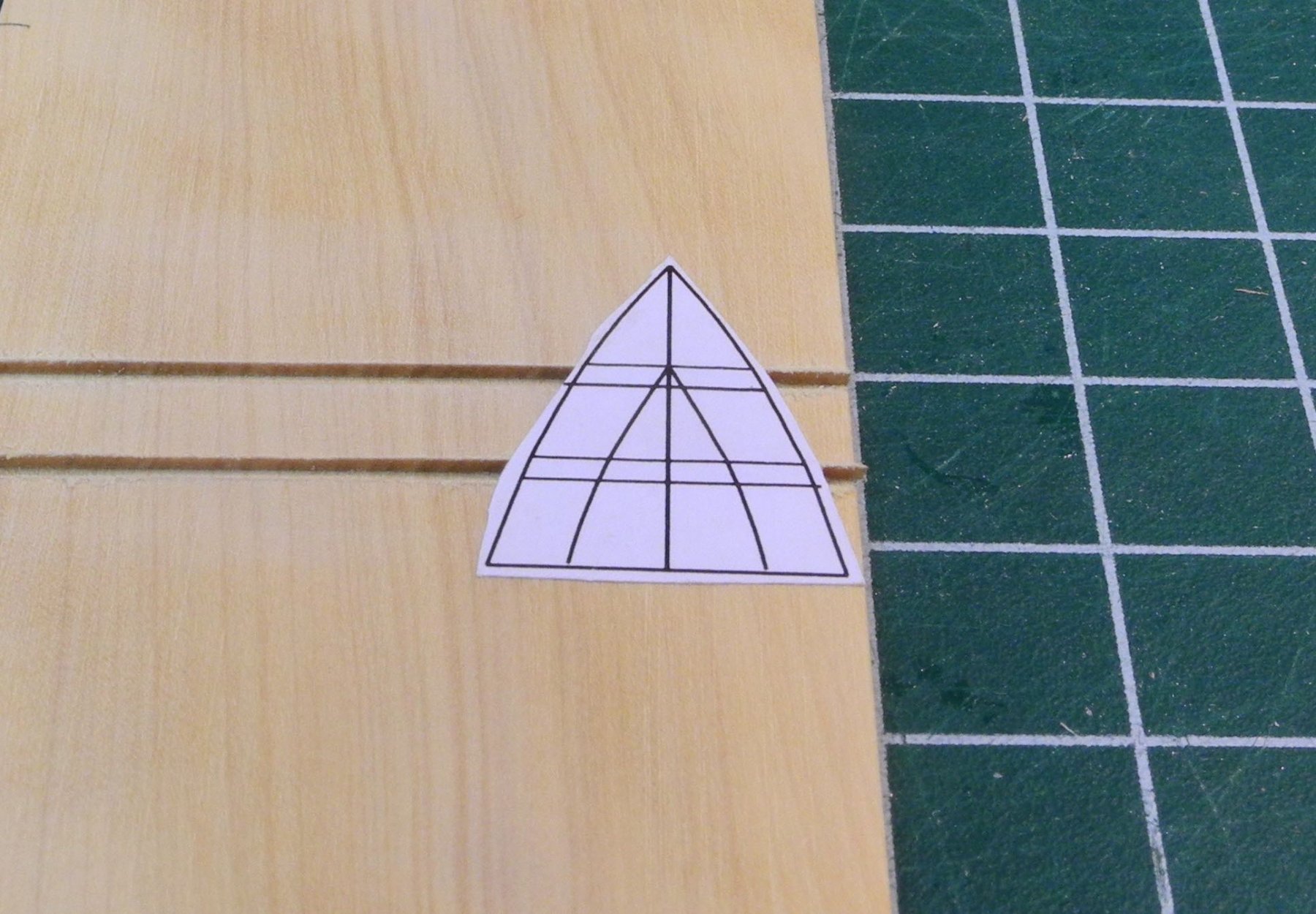
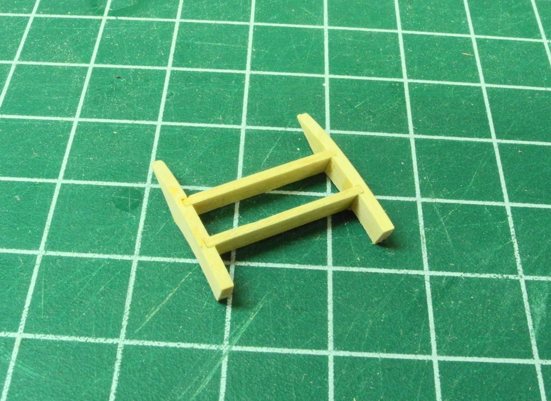
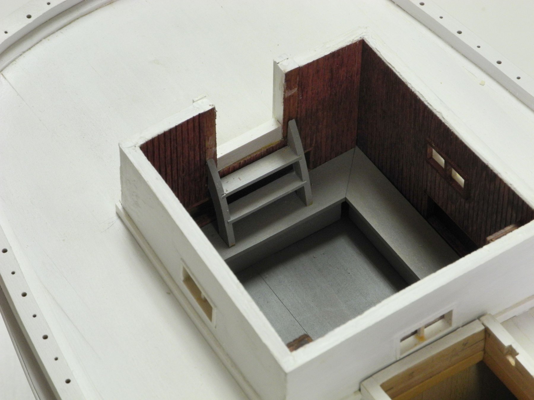
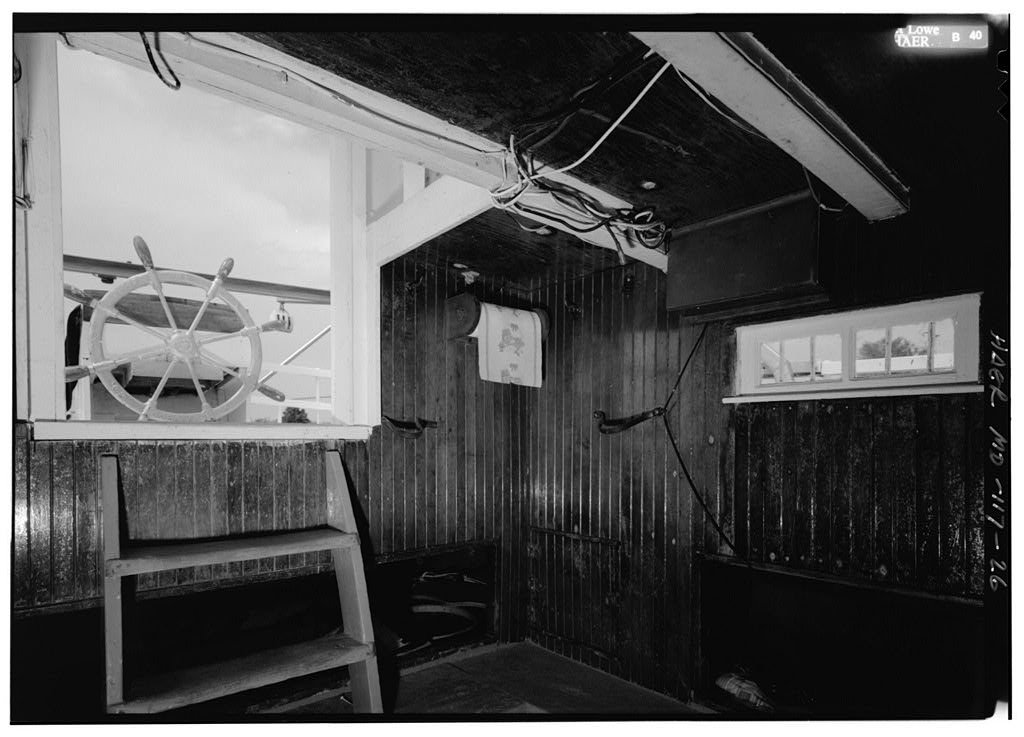
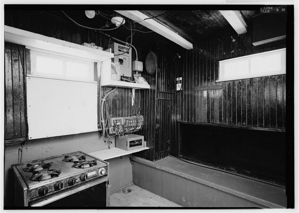
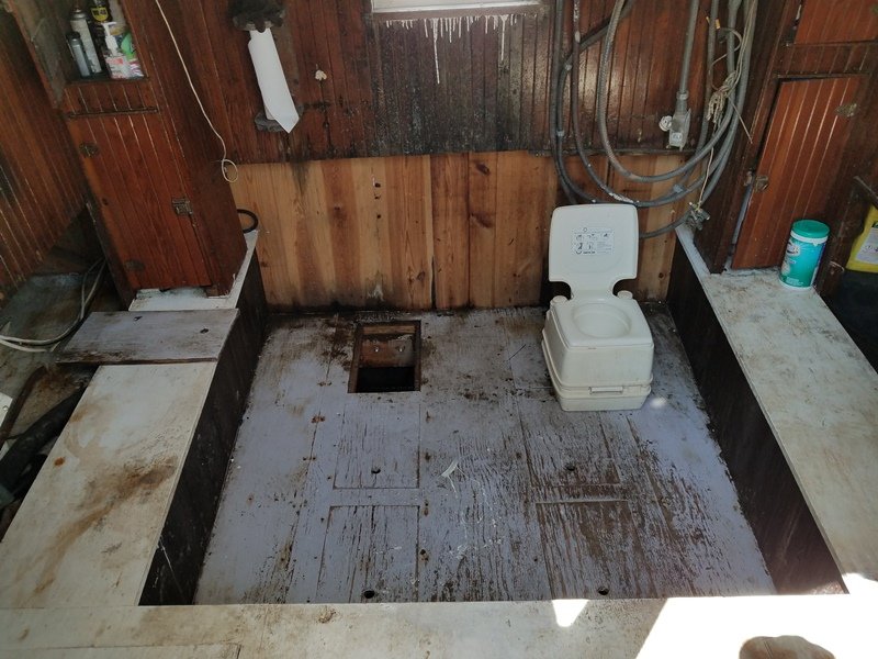
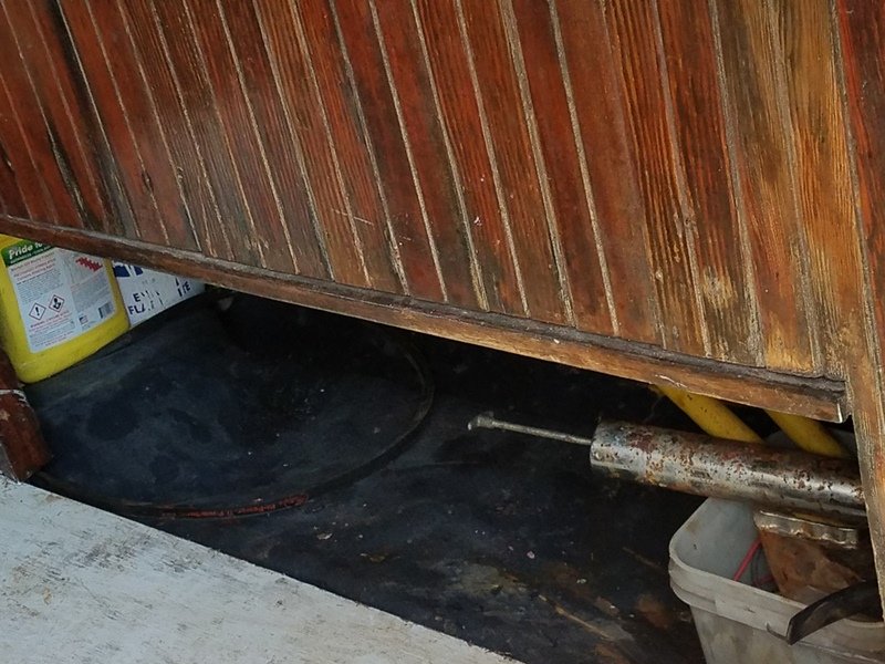
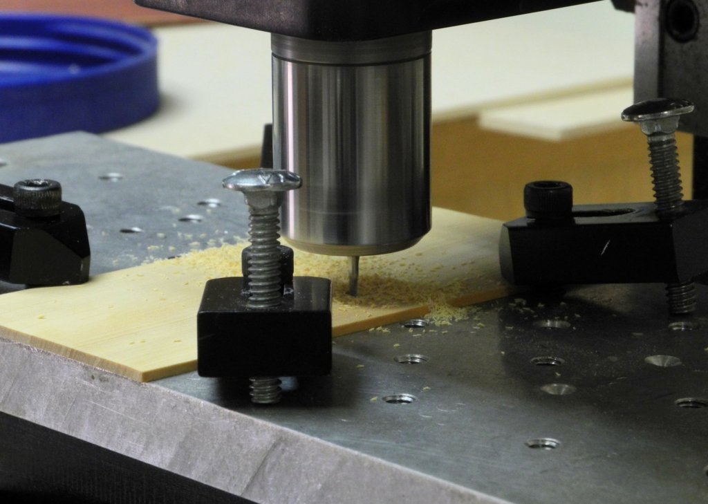
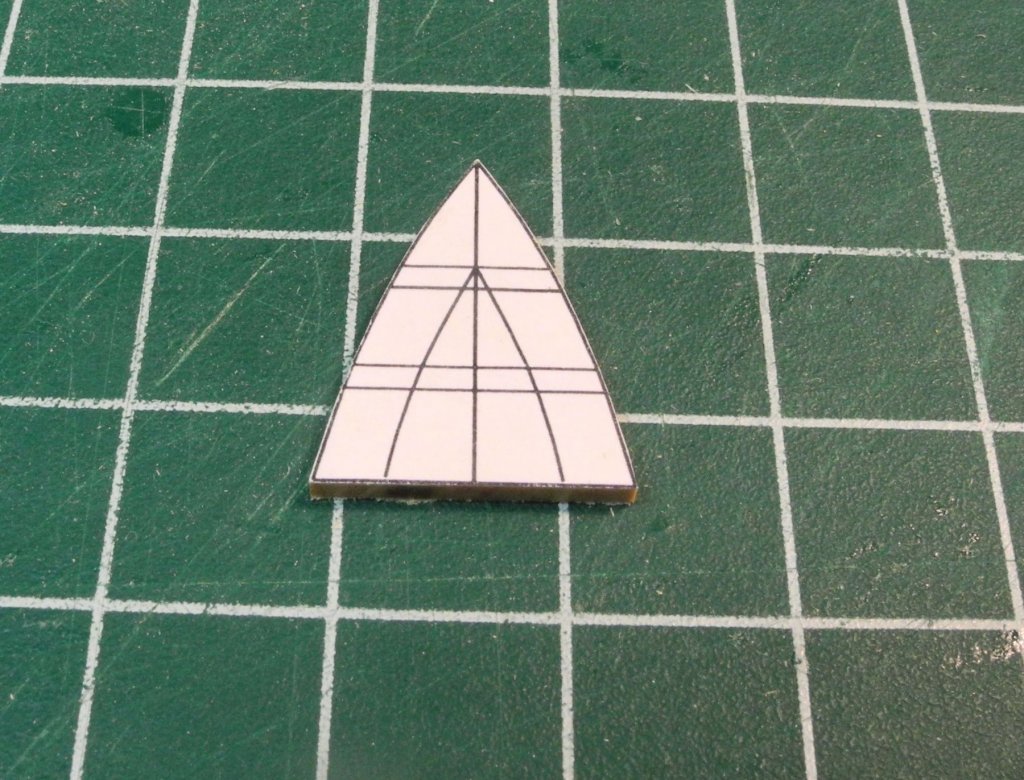
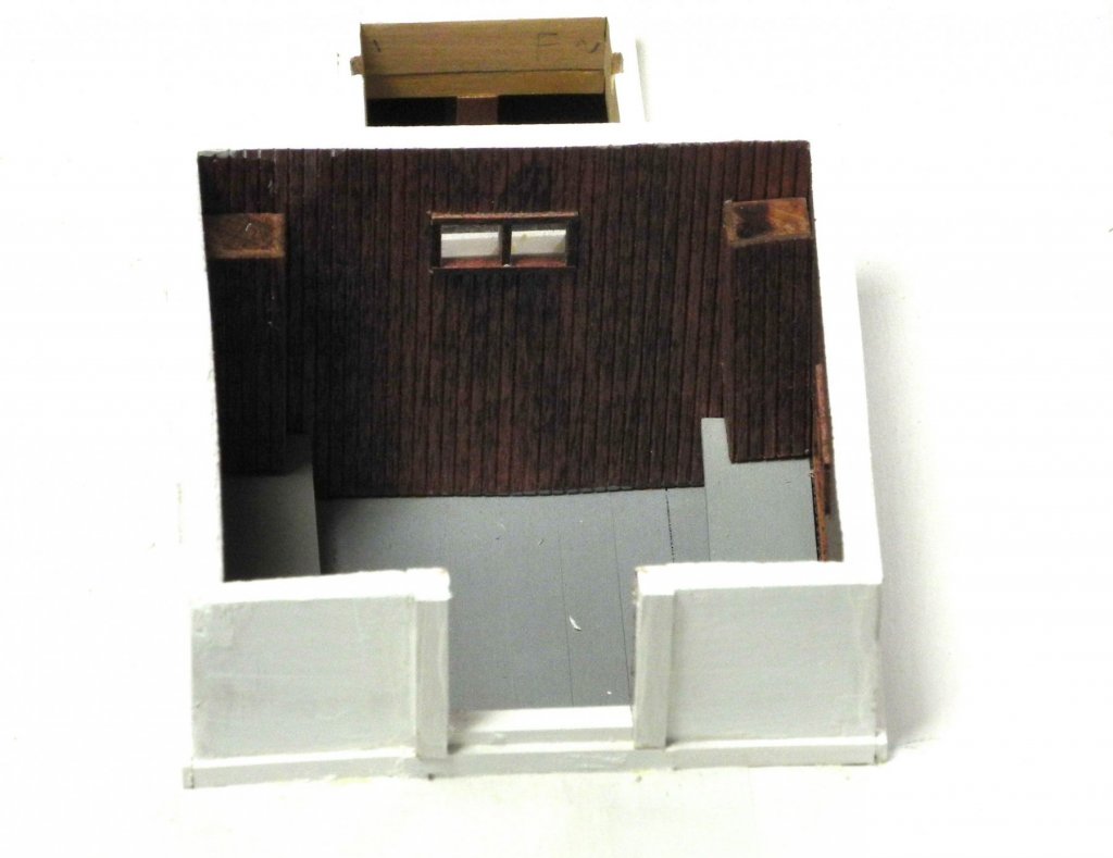
Part 42 – Cabin Interior After building the structure of the cabin and doghouse, the interior of the cabin still needed to be fitted out. During the time of the HAER survey, Kathryn’s cabin contained a stove, electrical boxes, a fuse box, and other equipment in a fairly well-ordered arrangement, as seen in the following photos. Today, however, the cabin interior appears to have been neglected, and is no longer used for overnight living arrangements. Since the model is being built to reflect Kathryn’s status as of the HAER survey, some fitting out of the cabin was needed. The first item was the construction of the low benches, called settees, along the port, starboard, and aft walls of the cabin. The construction approach for settees in the model was simplified. The tops were cut and shaped to the proper dimensions, while the sides that would show consisted of thick pieces of wood that eliminate the need for framing. The settees were constructed prior to installation. The settees were painted while outside the model, and were then installed. The companionway (ladder) reaches the top of the aft settee. Before the ladder could be installed, however, the aft wall of the cabin needed to be completed. The framing of the door was installed, and a watertight sill at the threshold was also installed. Kathryn’s ladder has curved sides and is relatively short. The first step in making the ladder was to mill two slots for the treads in a piece of stock. The drawing of the ladder sides was glued to the milled stock, making sure treads in the drawing were aligned with the milled slots. The ladder sides were then cut out and trimmed. Assembling and gluing the ladder was straightforward. After painting, the ladder was installed. Two narrow columns, simulating the cabin’s cabinets, were faced using the cabin’s paneling and were installed. The construction of the cabin is now mostly completed. The remaining cabin-related work is the installation of the cabin doors, which will be completed at a later step. Thanks everyone.


- 878 replies
-
- 16
-
-
Thanks Popeye. The hatch has been added to “lessons learned” - and that list is getting pretty long!