Mahuna
-
Posts
1,504 -
Joined
-
Last visited
Content Type
Profiles
Forums
Gallery
Events
Everything posted by Mahuna
-
 Thanks Allan - the HAER documentation is a great source of info for this kind of scratch build. There's an additional advantage for Kathryn - her recent rebuild was fairly well documented with photos. Thanks Mike. The skipjack is unique to the Chesapeake bay area, and unfortunately the number of these boats is dwindling.
 -
Thanks Michael. I always appreciate seeing the approach other modelers use, so I thought it would be appropriate to include a description of some of the processes in the log. Thanks Russ. Like you, I have a preference for workboats over warships. And the fact that they are generally smaller does allow working at a more comfortable scale. Thanks Albert.
-
Great progress, Patrick. I love the level of detail you're able to include. I think a scale bottle of Dom P and some champagne glasses would really set off the bar area.
-
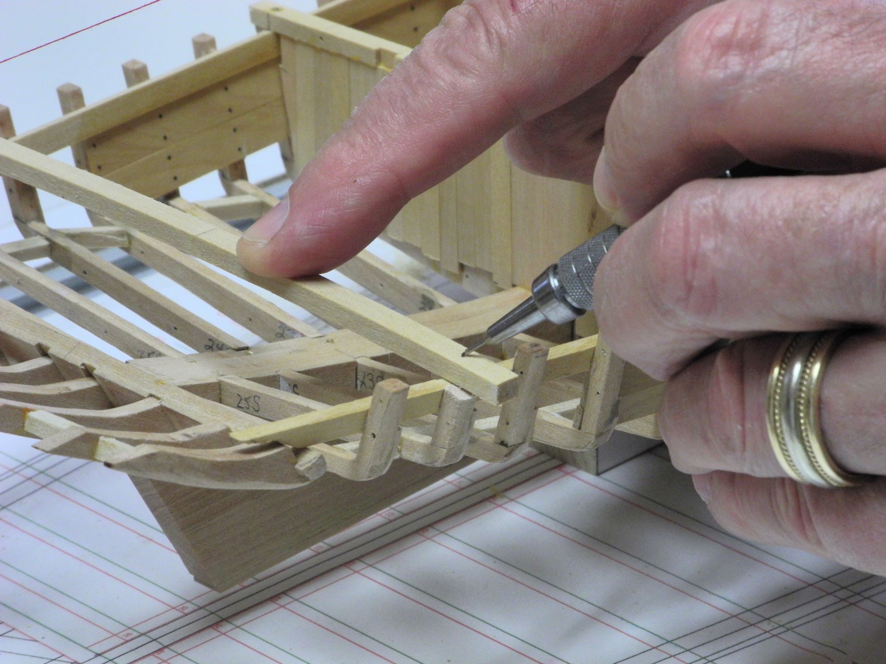
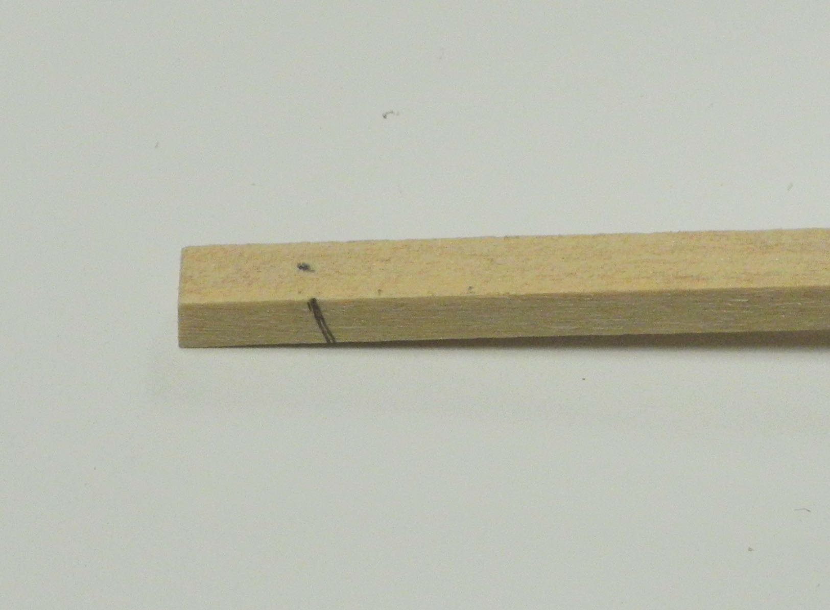
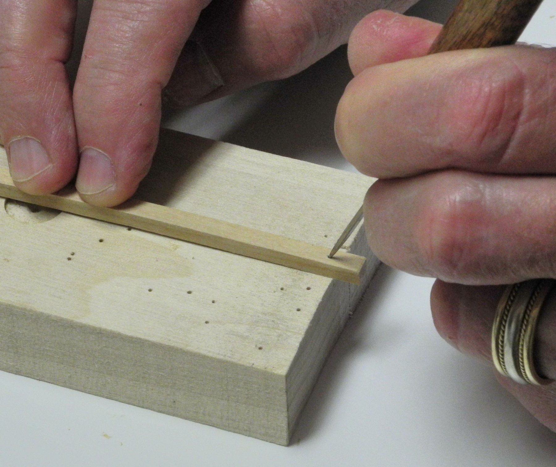
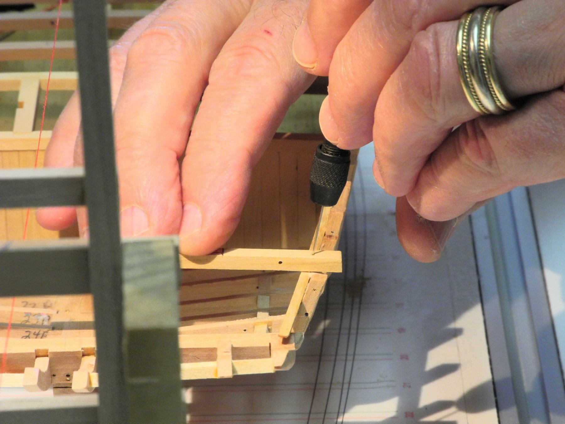
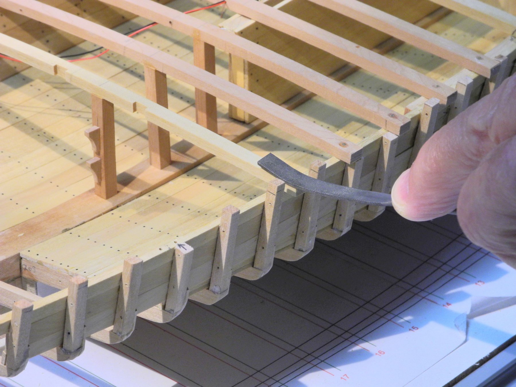
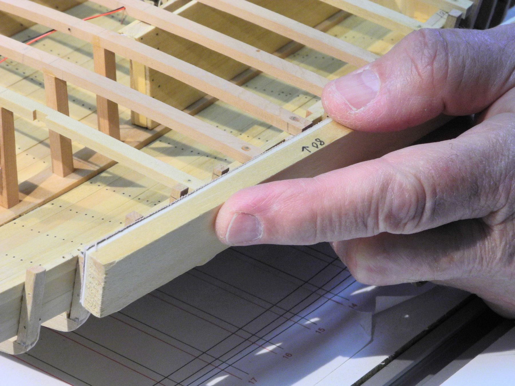
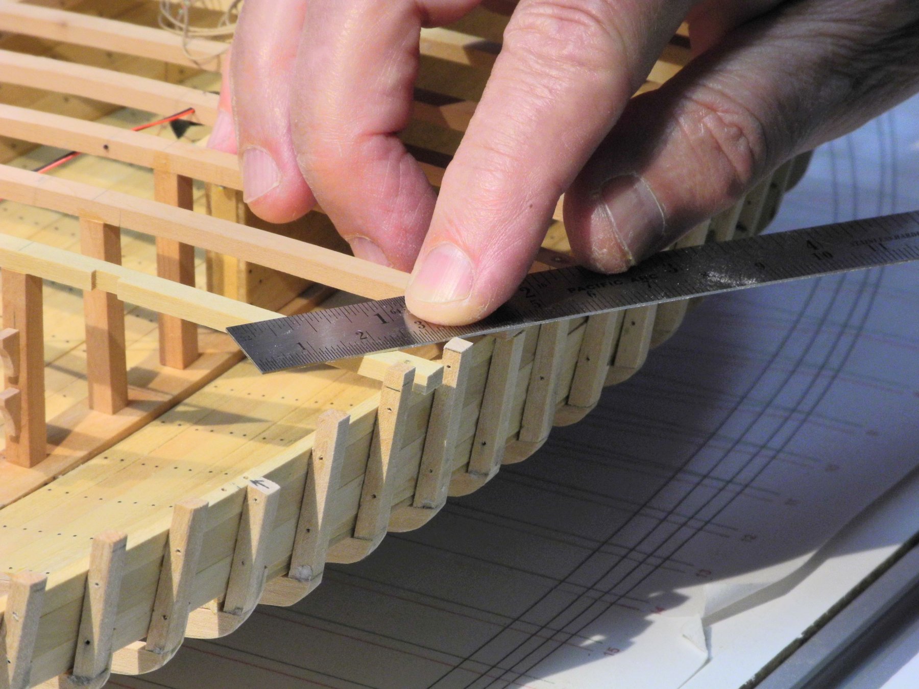
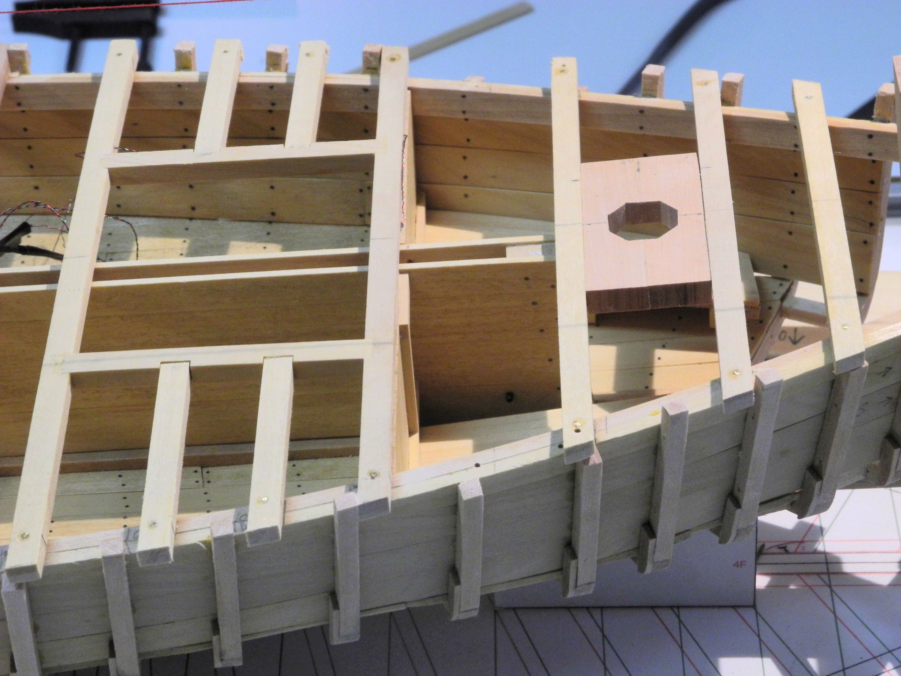
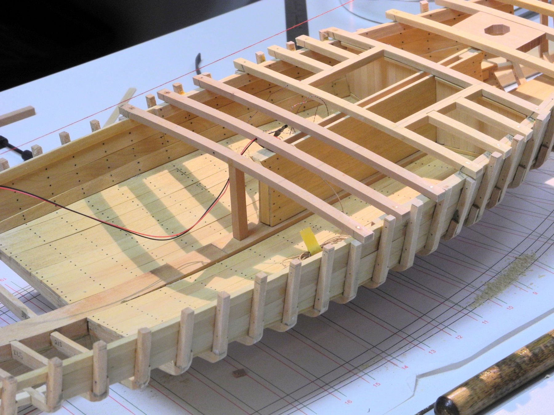
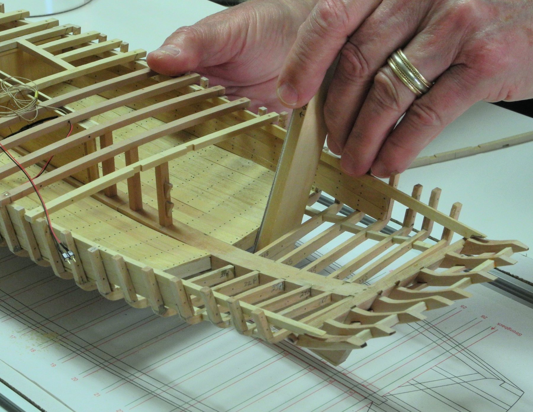
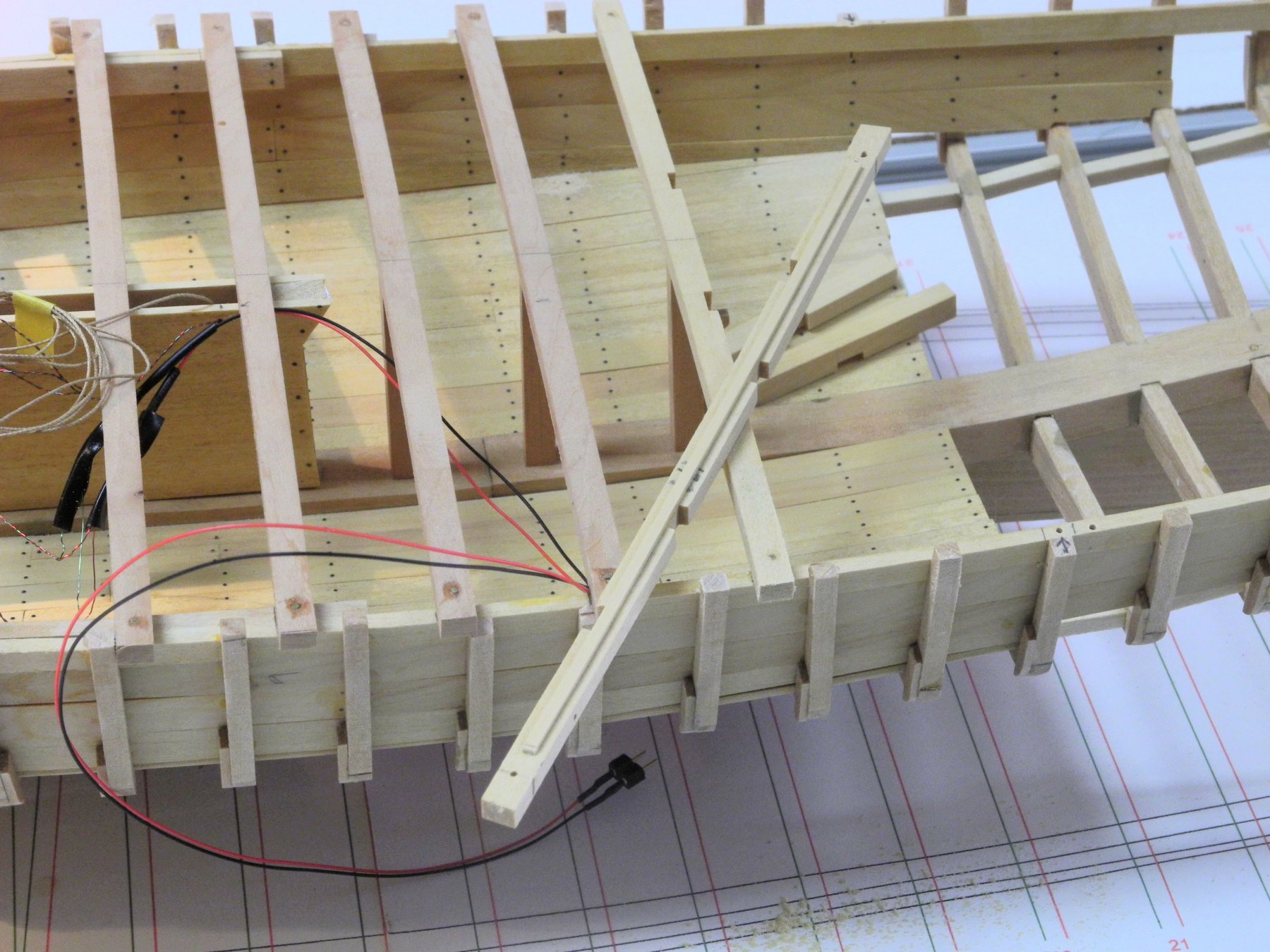
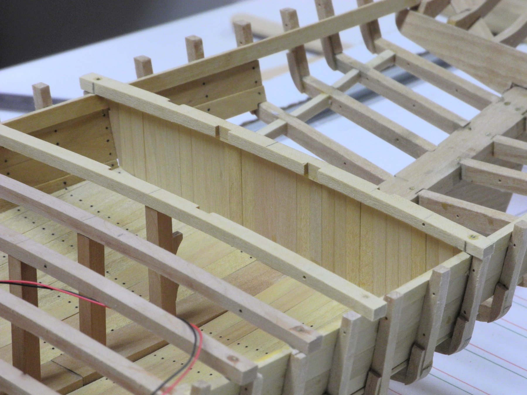
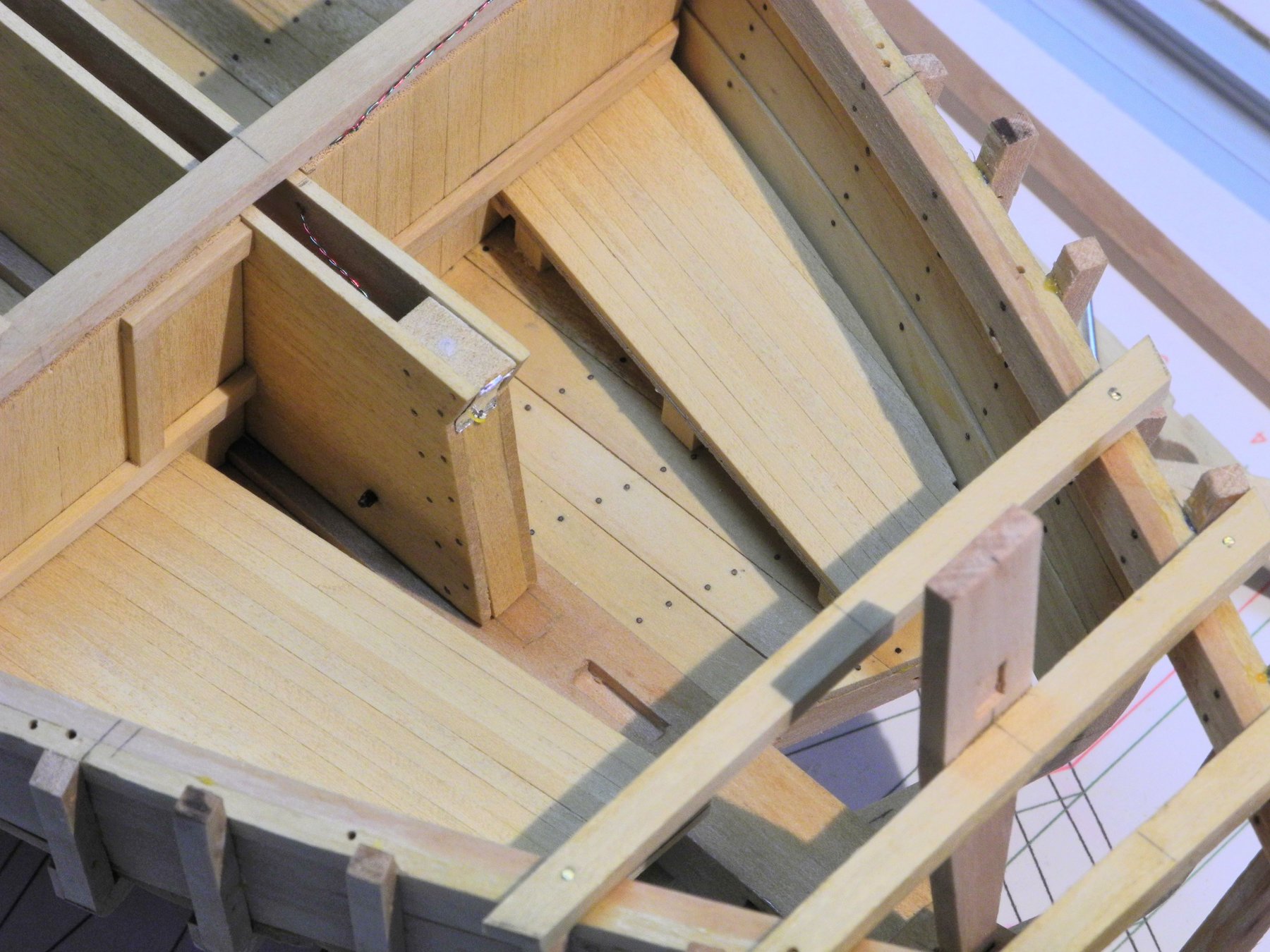
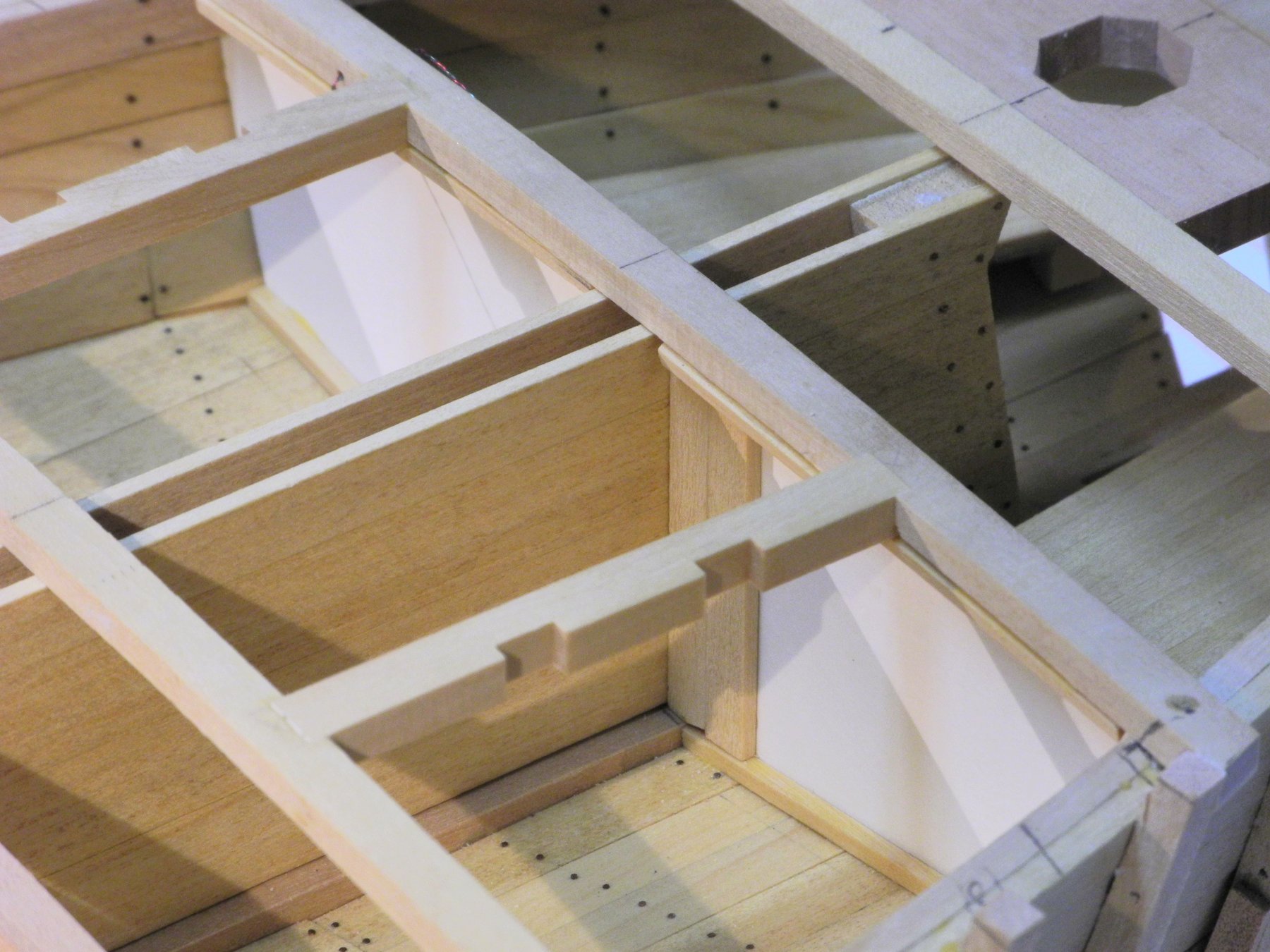
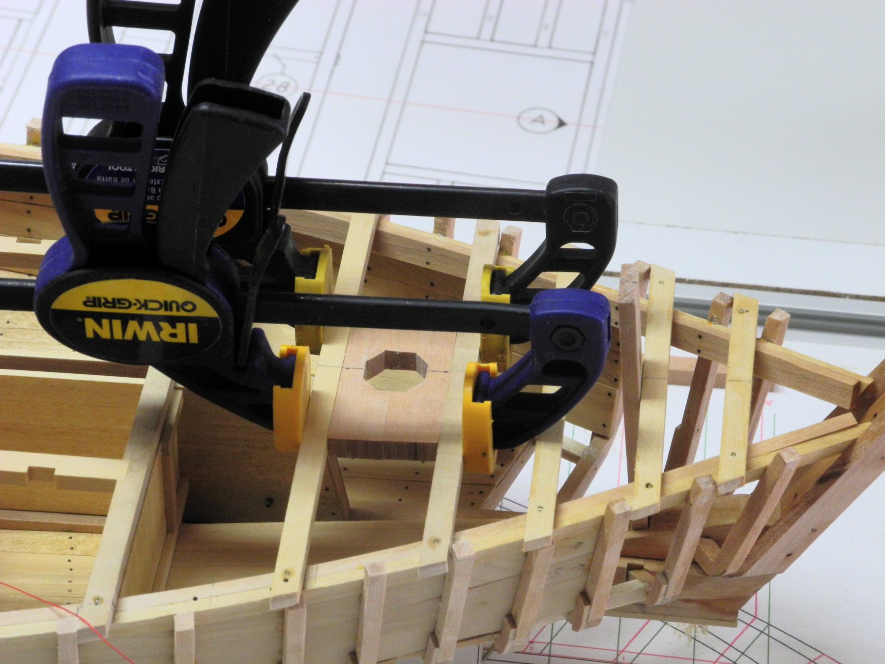
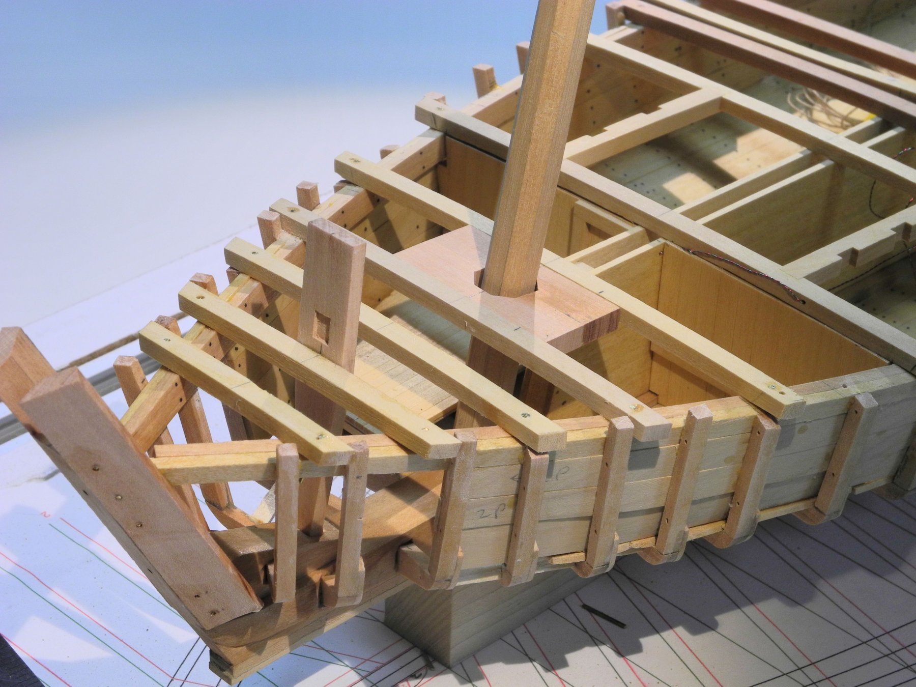
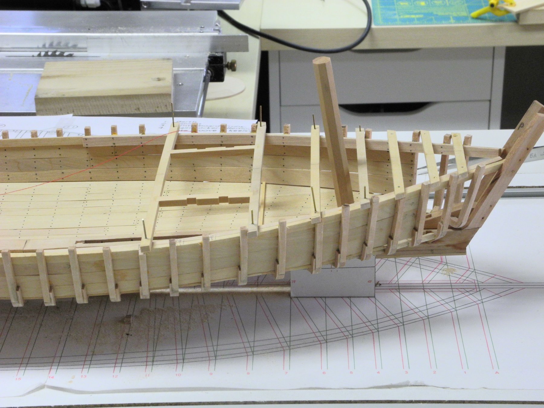
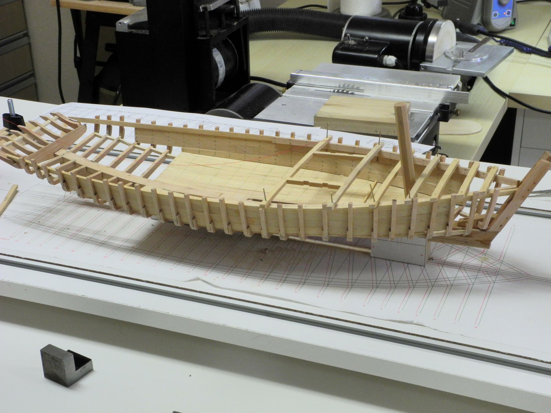
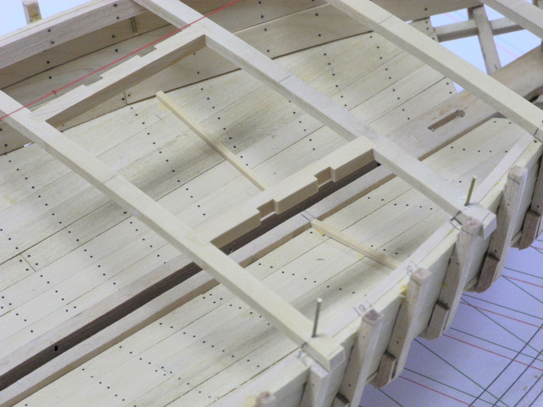
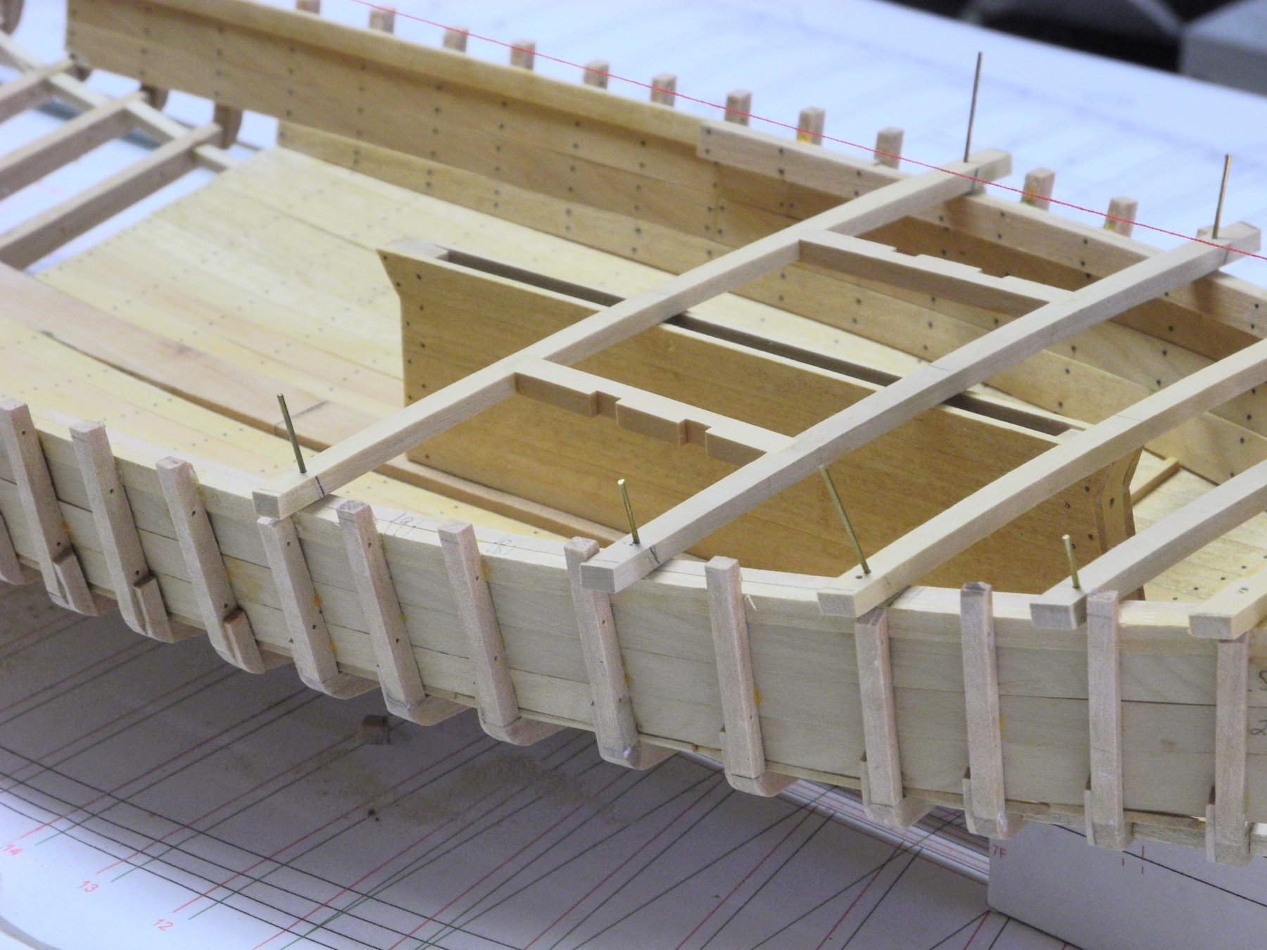
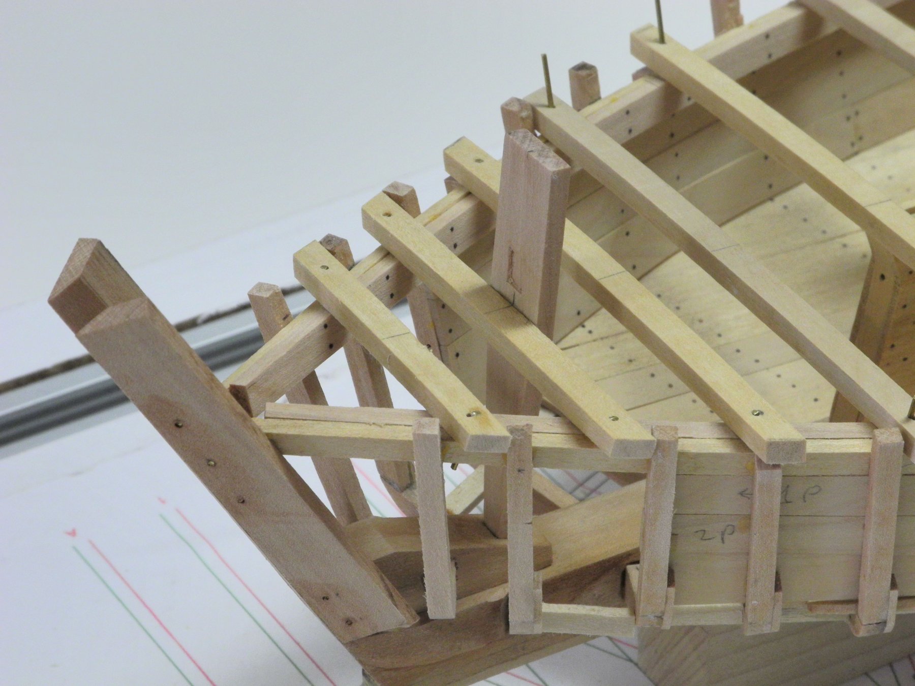
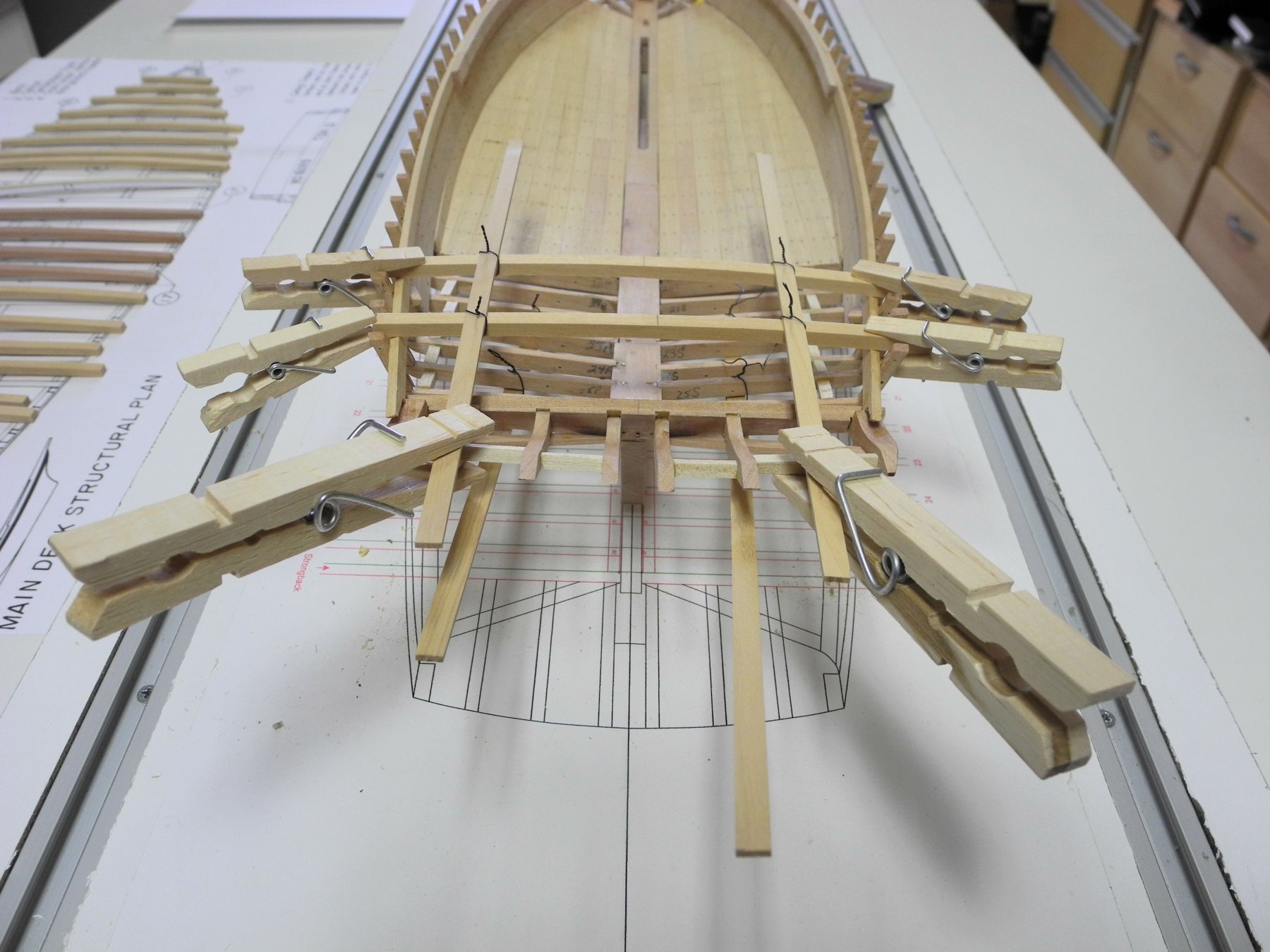
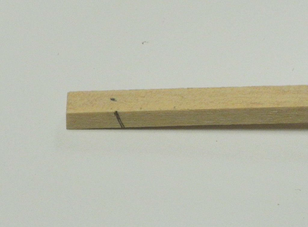
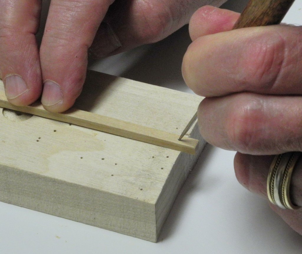
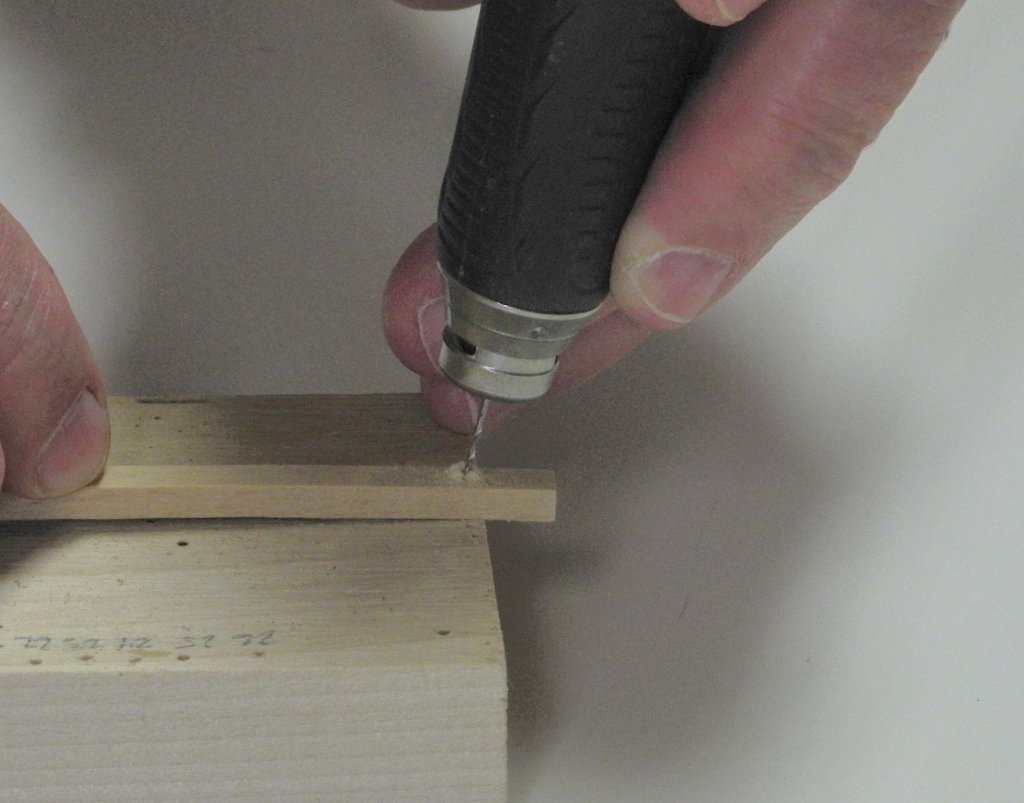
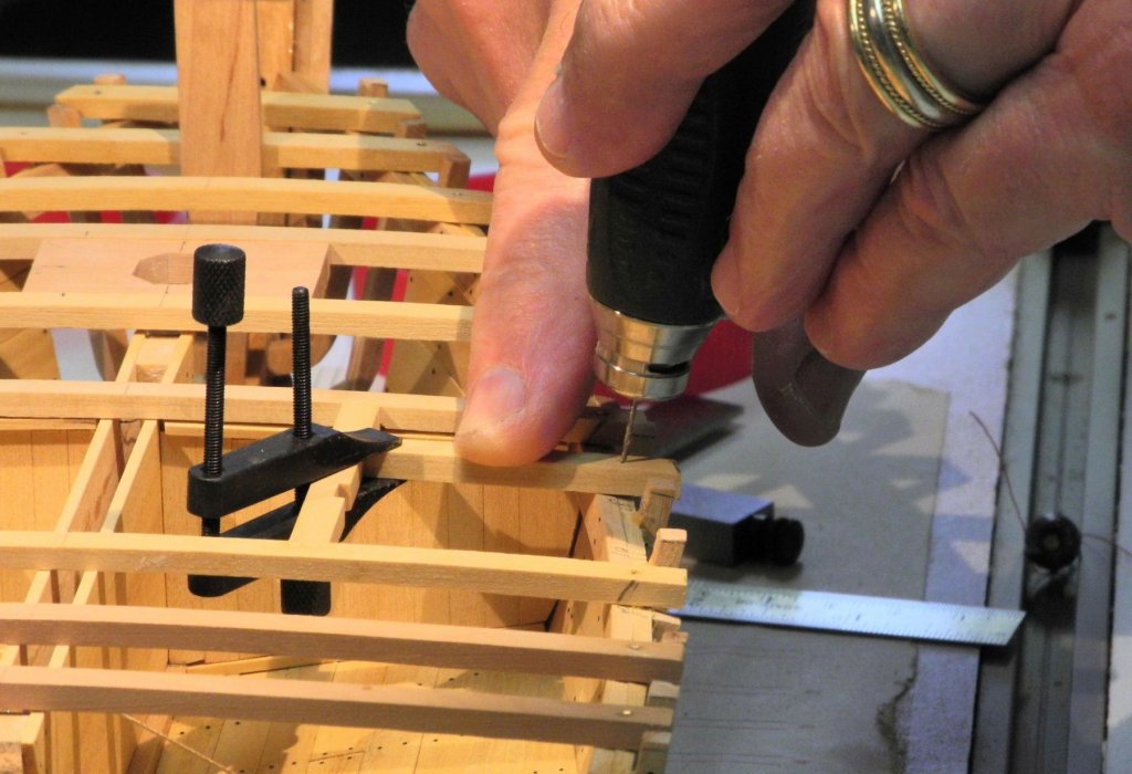
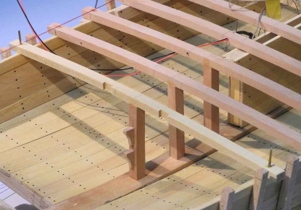
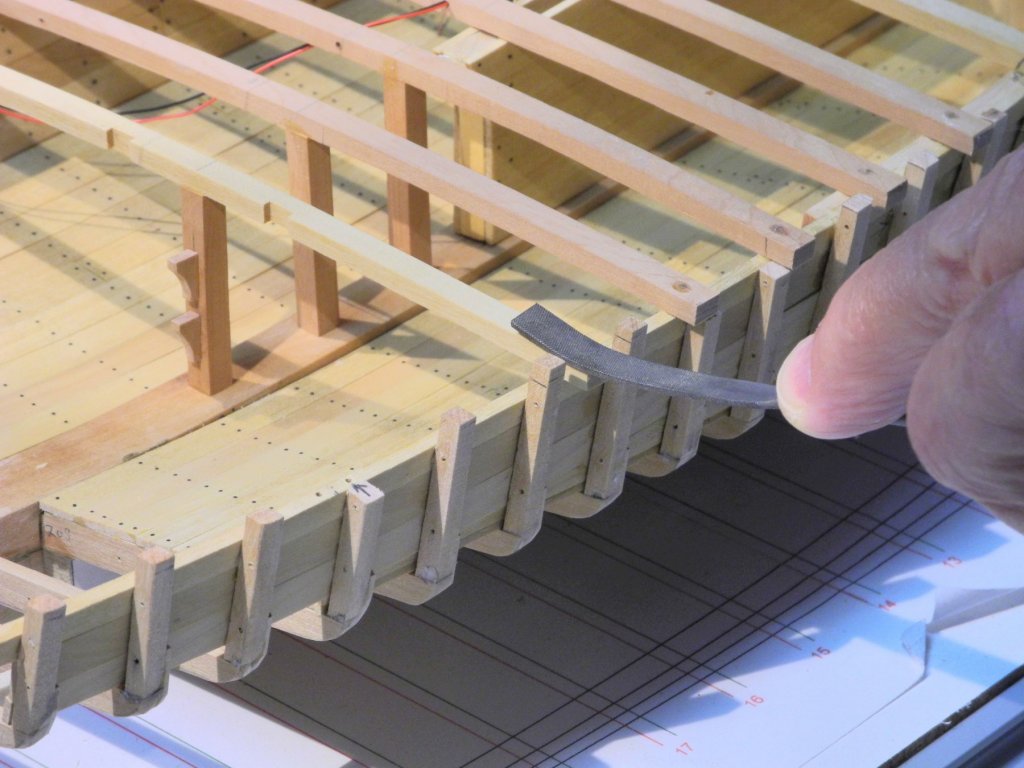
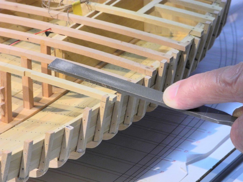
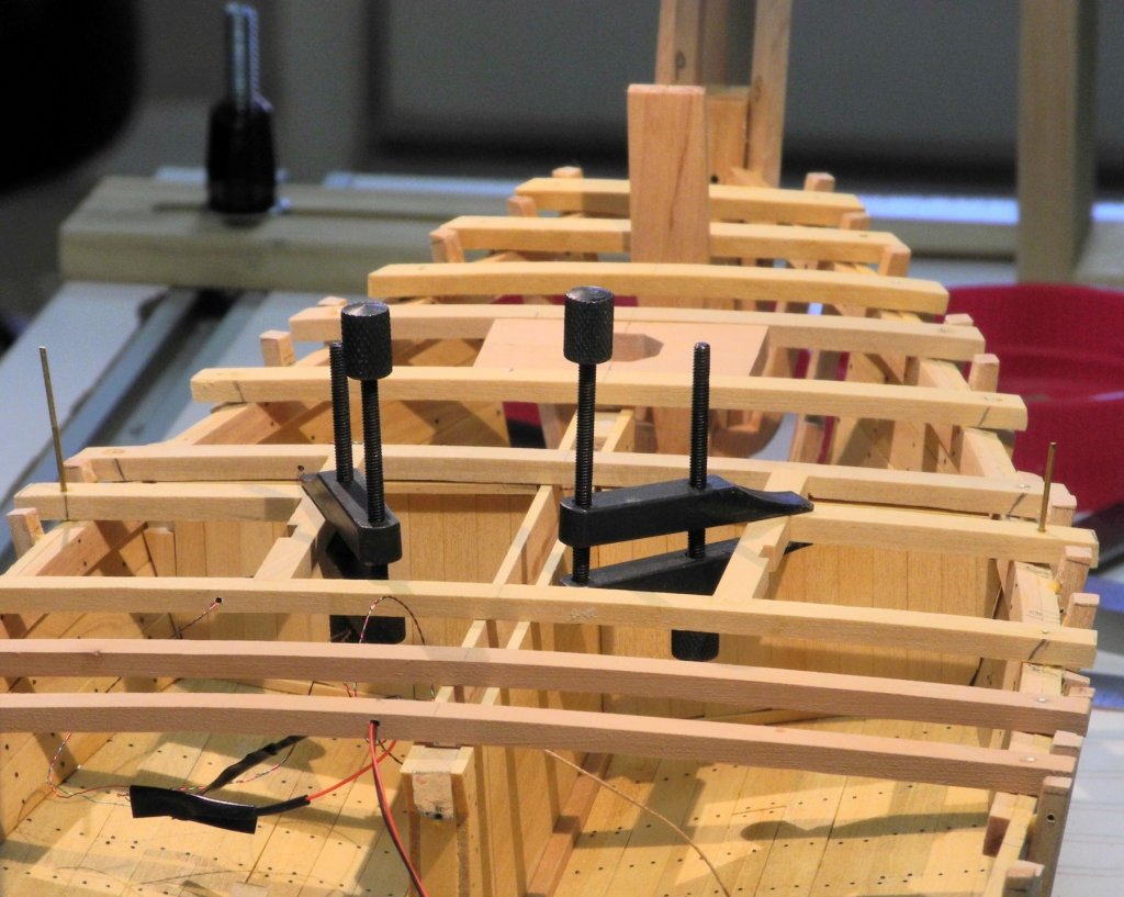
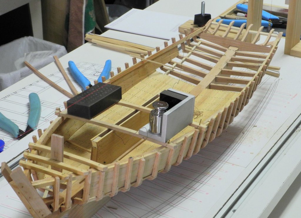
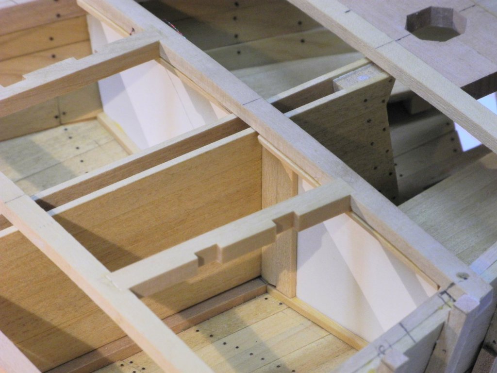
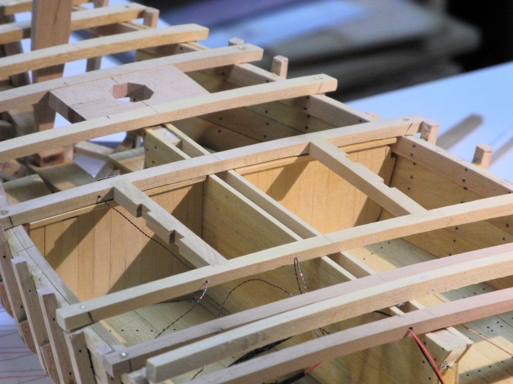
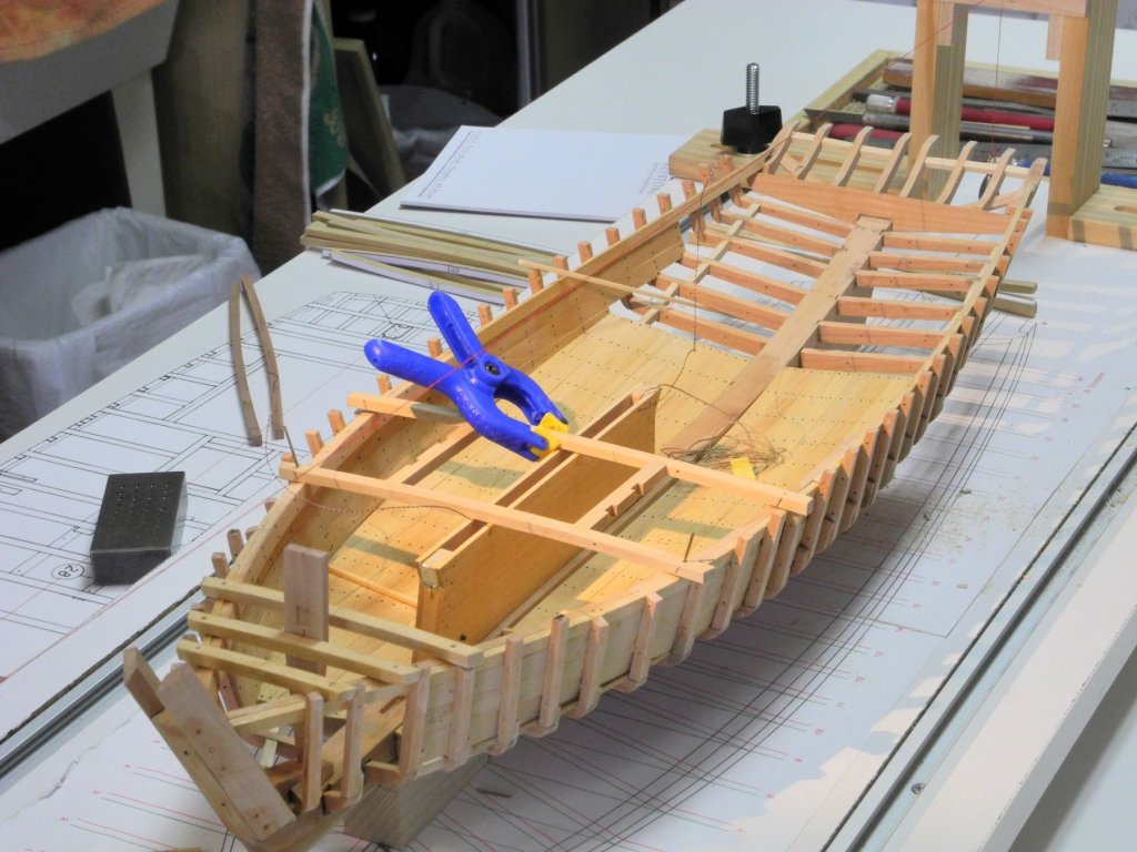
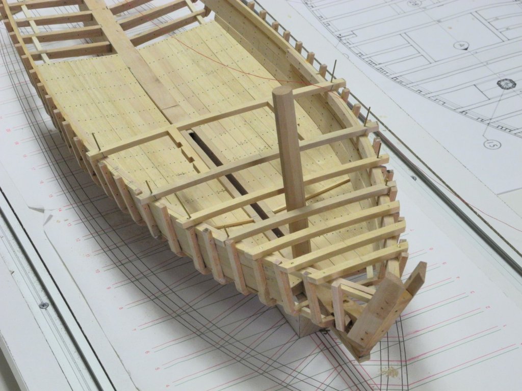
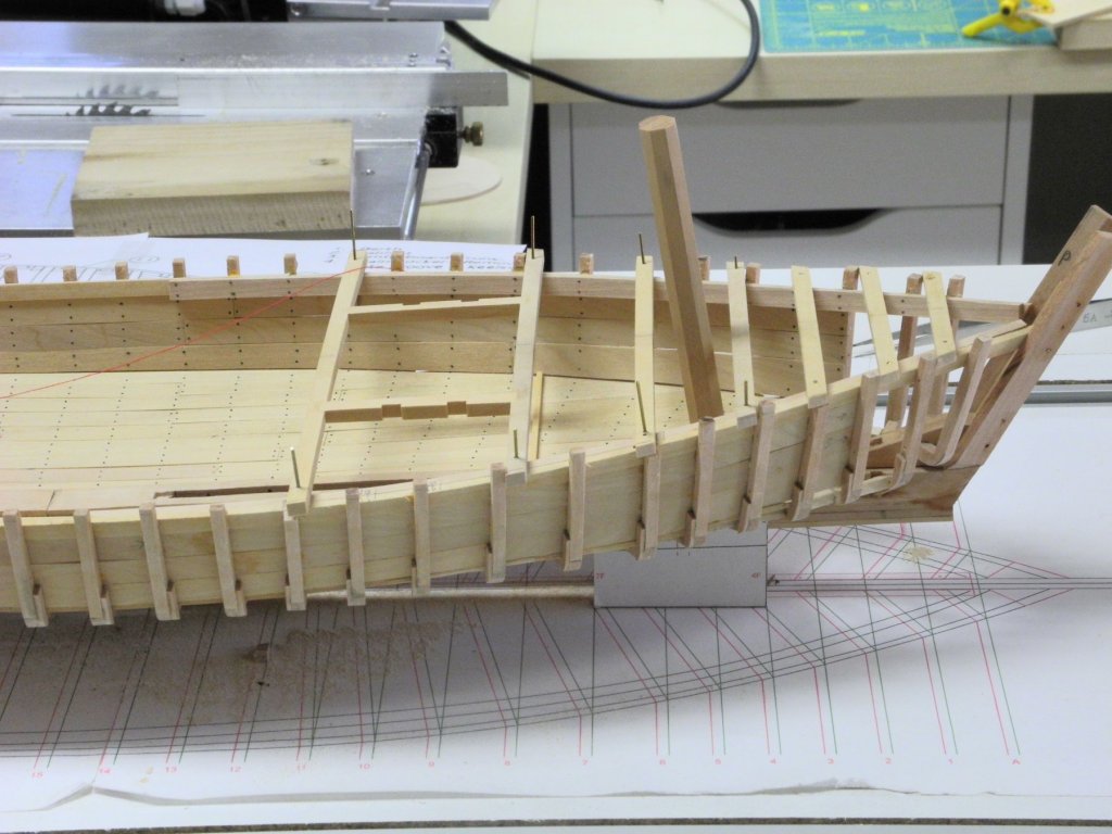
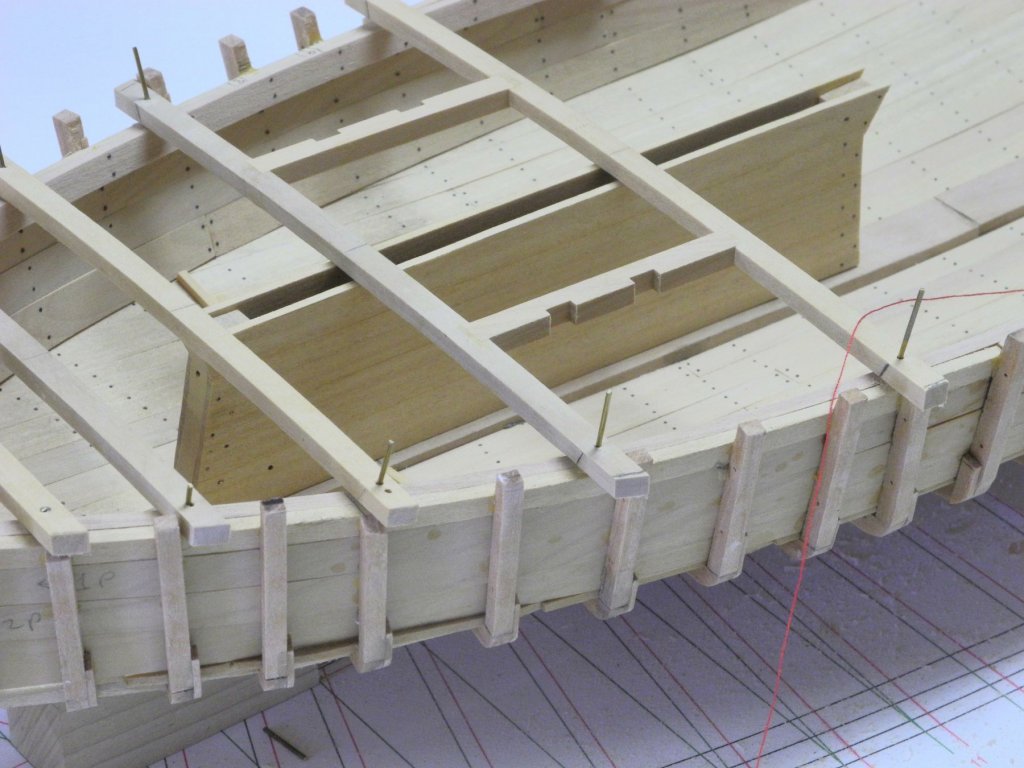
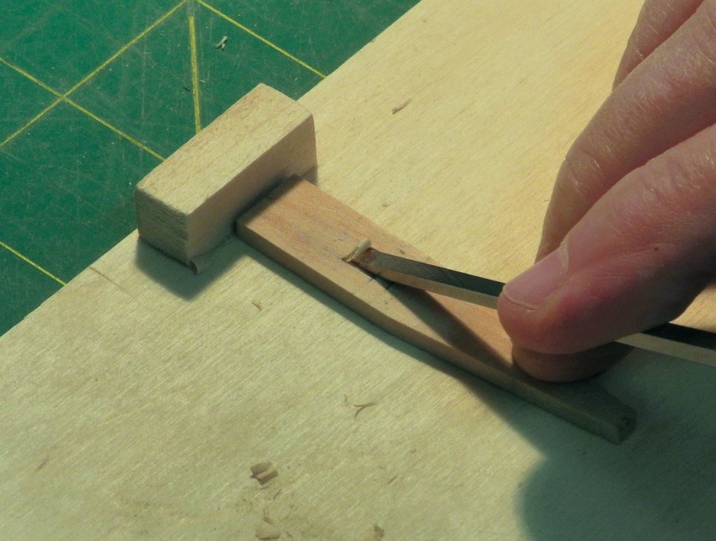
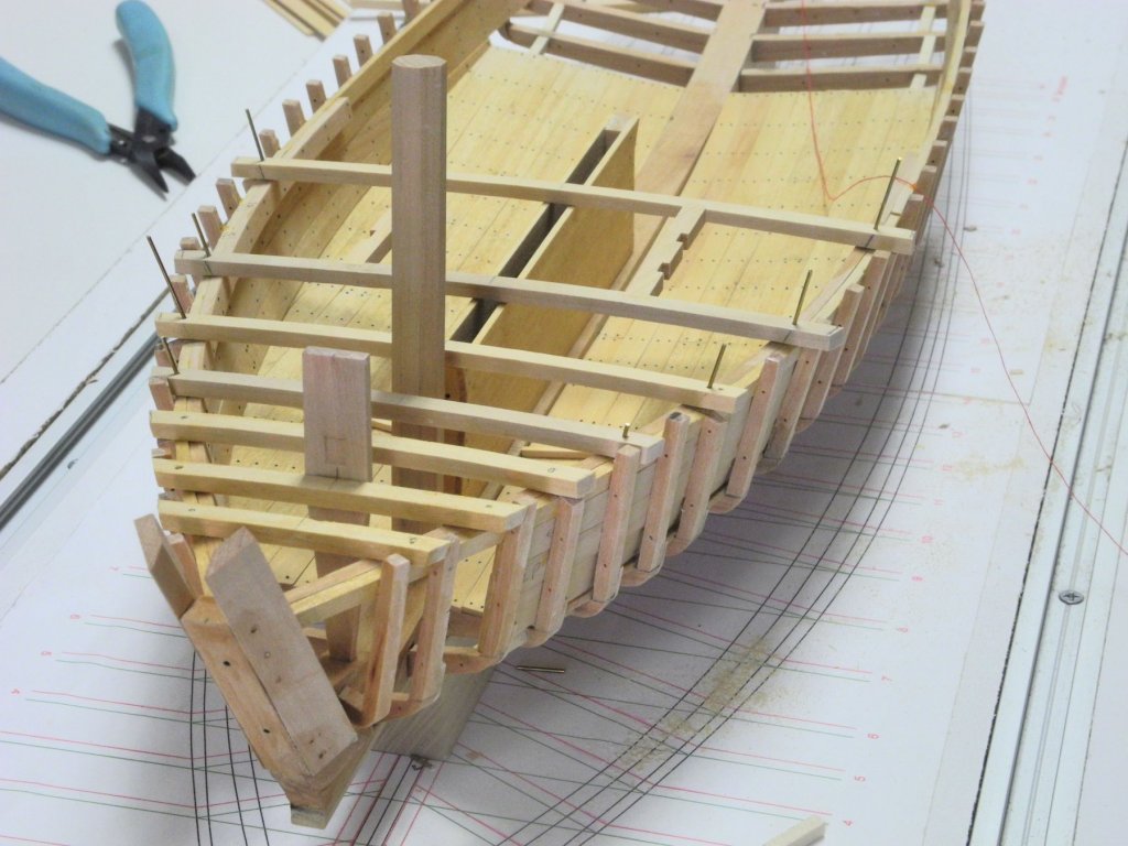
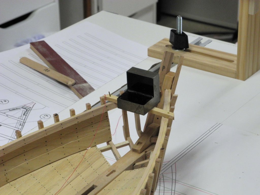
Part 21 – Deck Beam Installation (cont’d) Installation of deck beams has been progressing. The installation of the beams follows a basic process. The first step is to position the beam in the appropriate location, making sure that the centerline on the beam lines up with the centerline string of the shipway. When positioning is correct, the location of the functional bolt is marked on each end of the beam. Since the bolt will be secured to the deck clamp, the angle of the deck clamp is estimated and drawn on the face of the deck beam. A very small awl is used to make a starter hole on the deck beam where the hole for the functional bolt will be drilled. The hole for the bolt is then drilled, being careful to align the drill bit with the angle drawn on the beam (above). A pin, held in a pin vise, is then fed through the drilled hole and is used to make a small mark on the deck clamp. This will verify that the angle of the drilled hole is correct. The hole through the clamp is then drilled by feeding the drill through the hole in the beam. PVA glue is applied to the deck clamps at the position of the deck beam, and 1/32” brass rods are then CA glued through the drilled holes as functional bolts. Once the glue has set, the bolt is cut to the level of the deck beam top, and a riffler file is used to file the brass rod flush with the surface of the deck beam. The end of the deck beam is then sanded down so that is faired with the frames. This will provide a smooth flow of the sheer plank. The top of some of the frames is higher than the top surface of the deck beam. This is checked by sliding a straight edge down the deck beam. If the top of the frame obstructs the movement of the straight edge, it needs to be reduced by filing or sanding until it’s at the correct height. Once the above process is completed, the deck beam is properly located, securely attached to the deck clamp, faired, and the surrounding frames are in line with the top of the deck beam. The holds have half-beams supporting the sides. A full deck beam is used to create the half beams, with an appropriate length taken from outlying end of the full deck beam to ensure that the proper deck camber is maintained. A small machinist screw clamp is used to hold the inboard end of the half beam in place, while the above procedure is followed for the outboard end of the half beam. The following photo shows the forward hatch fully framed out. All of the deck beams shown to this point are of pine (castello on the model). The four beams directly behind the forward hatch are oak (madrone on the model) since they support the weight of the dredge winder and motor. The first two of these oak beams are supported by the centerboard trunk. The following two beams are supported by stanchions sitting on the keelson. The next photo shows the first of these stanchions. In addition to the stanchions that support the oak beams, another stanchion is used to support the forward beam of the aft hold. This particular stanchion has foot steps attached to it for hold entry and egress. In the above photo, the ends of the ceiling planks are being sanded to be flush with the edge of the underlying frame. The aft bulkhead will be built at this location and attached to the aft end of that frame. Smoothing the ceiling plank ends will allow a clean seam where the bulkhead meets the ceiling planks. The deck beam that forms the top of the bulkhead has a small (1/32 x 1/32) strip attached to it to provide a consistent gluing surface for the top end of the bulkhead planks. The planks of the aft bulkhead were individually installed. Shaping of the two outer planks was required. Most of the deck beams are now in place. The remainder of the beams will be installed after the cabin has been designed and installed, since the remaining beams may interfere with some of the cabin work if installed too early. The work involved in planning and installing the cabin structures will be fairly complex, so it may be a little while before the next post. In the meantime, thanks everyone for following the Kathryn build, and for all of the “Likes”.


- 878 replies
-
- 25
-

-
Adjustable height table.
Mahuna replied to Ulises Victoria's topic in Modeling tools and Workshop Equipment
Hi Ulises I have one of the Ikea 'sit/stand' tables and really like it. I like being able to adjust the table height based on what I'm working on. Here's a link to the product on the Ikea web site: http://www.ikea.com/us/en/catalog/products/S49084965/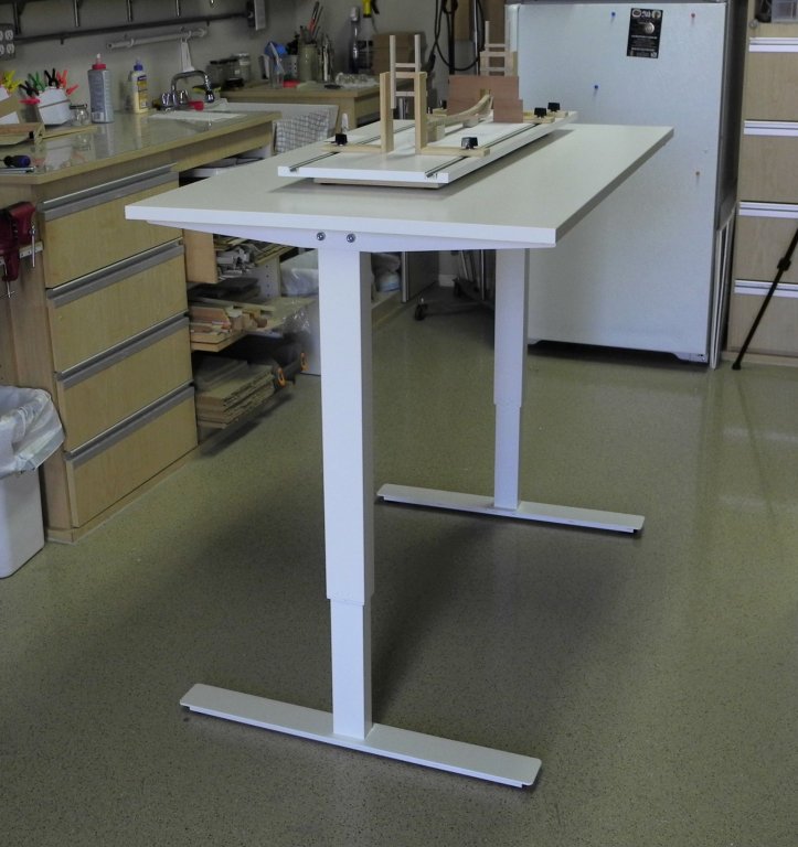
-
Thanks Michael Thanks Carl. I mostly used tweezers to sneak the planks in, and the beams are pretty secure since they are pinned with brass rods.
-
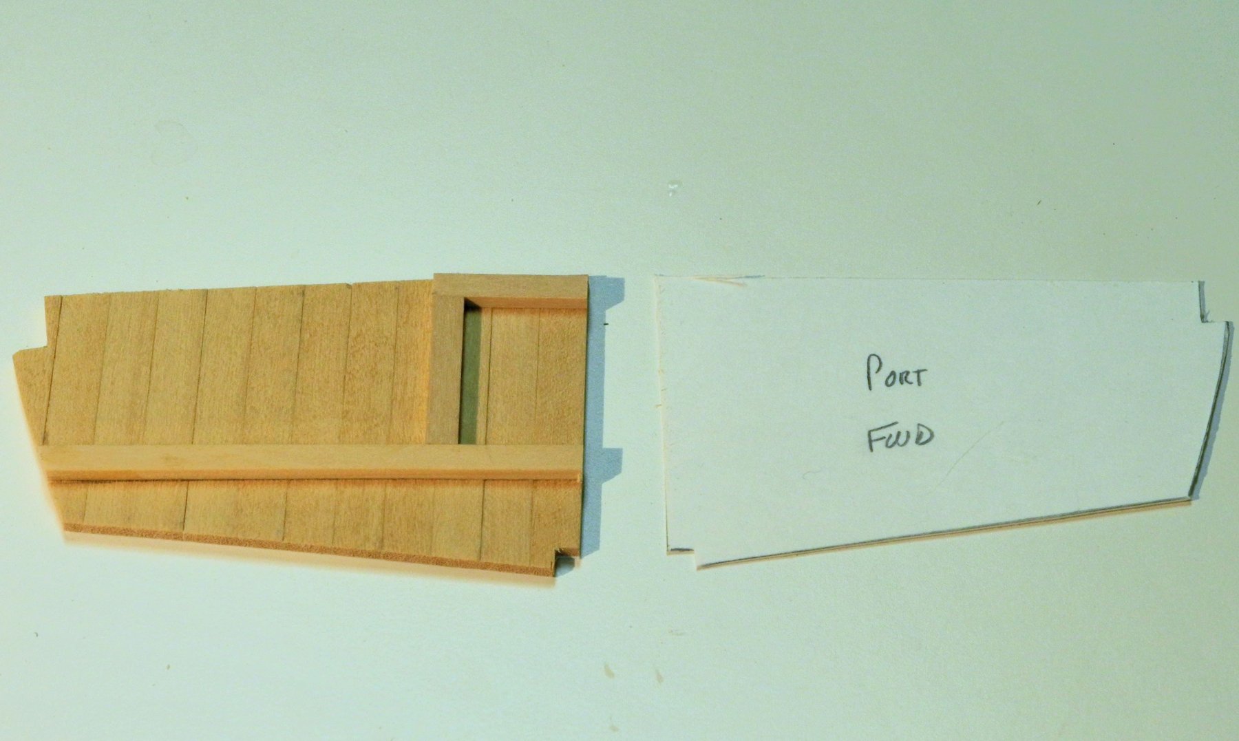
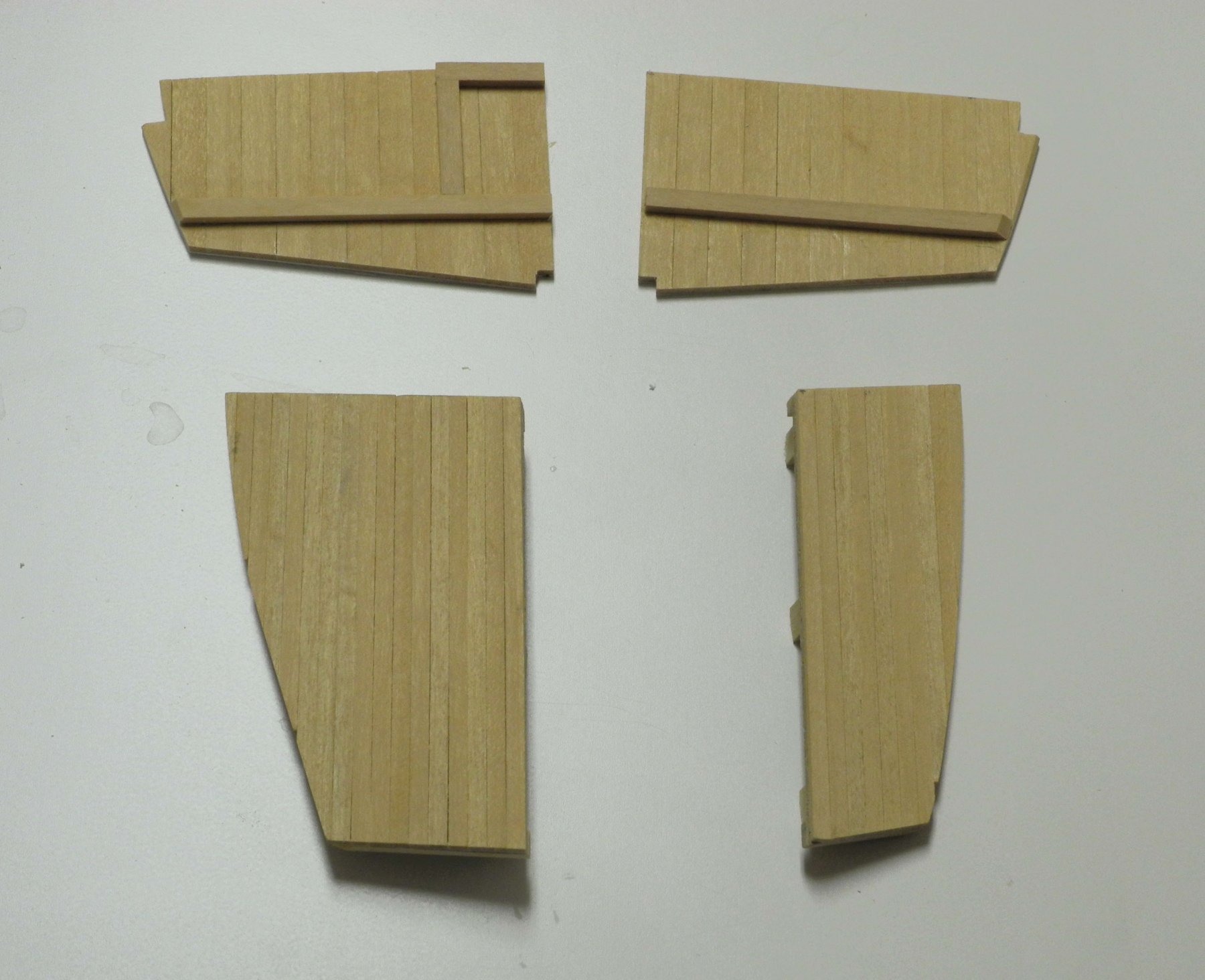
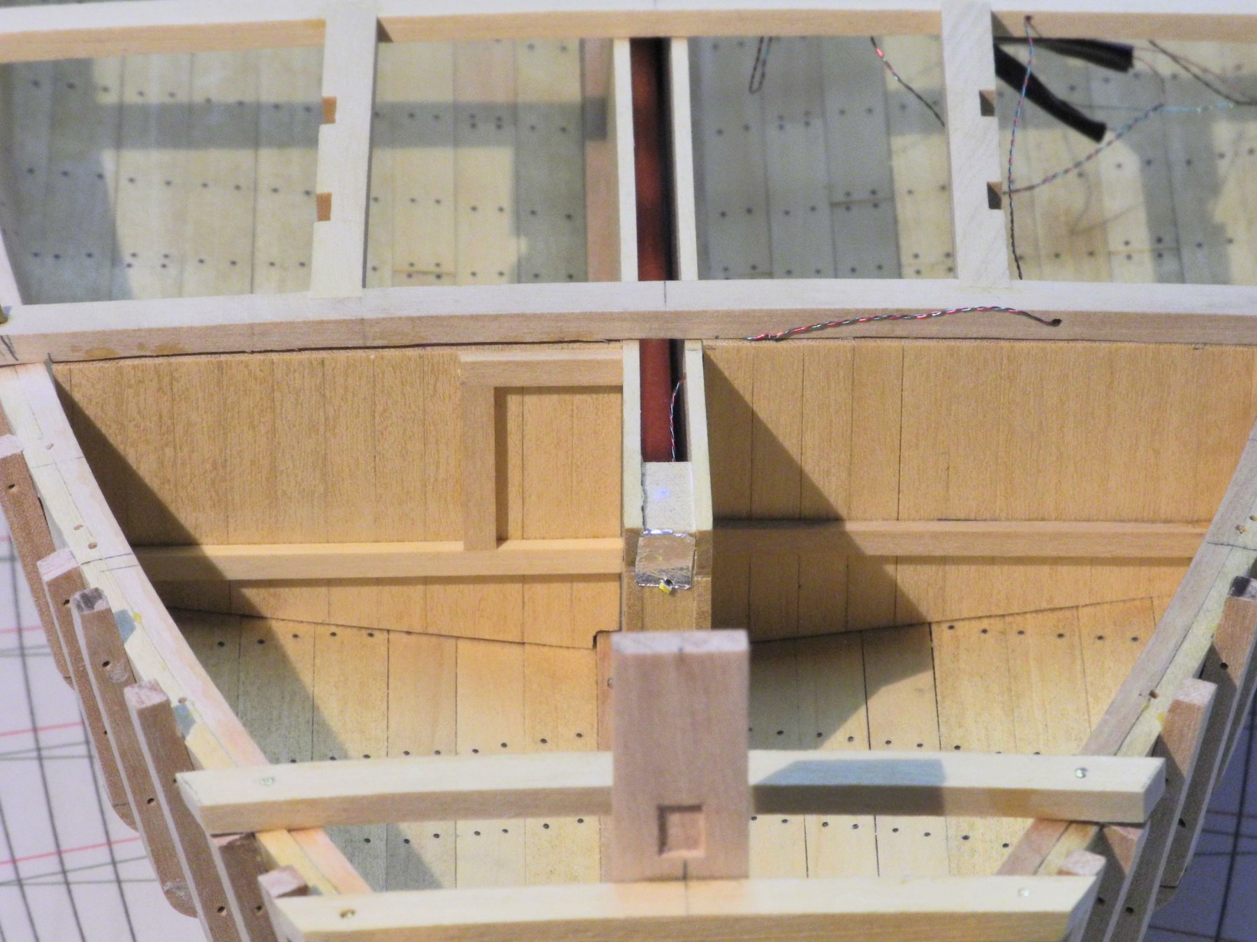
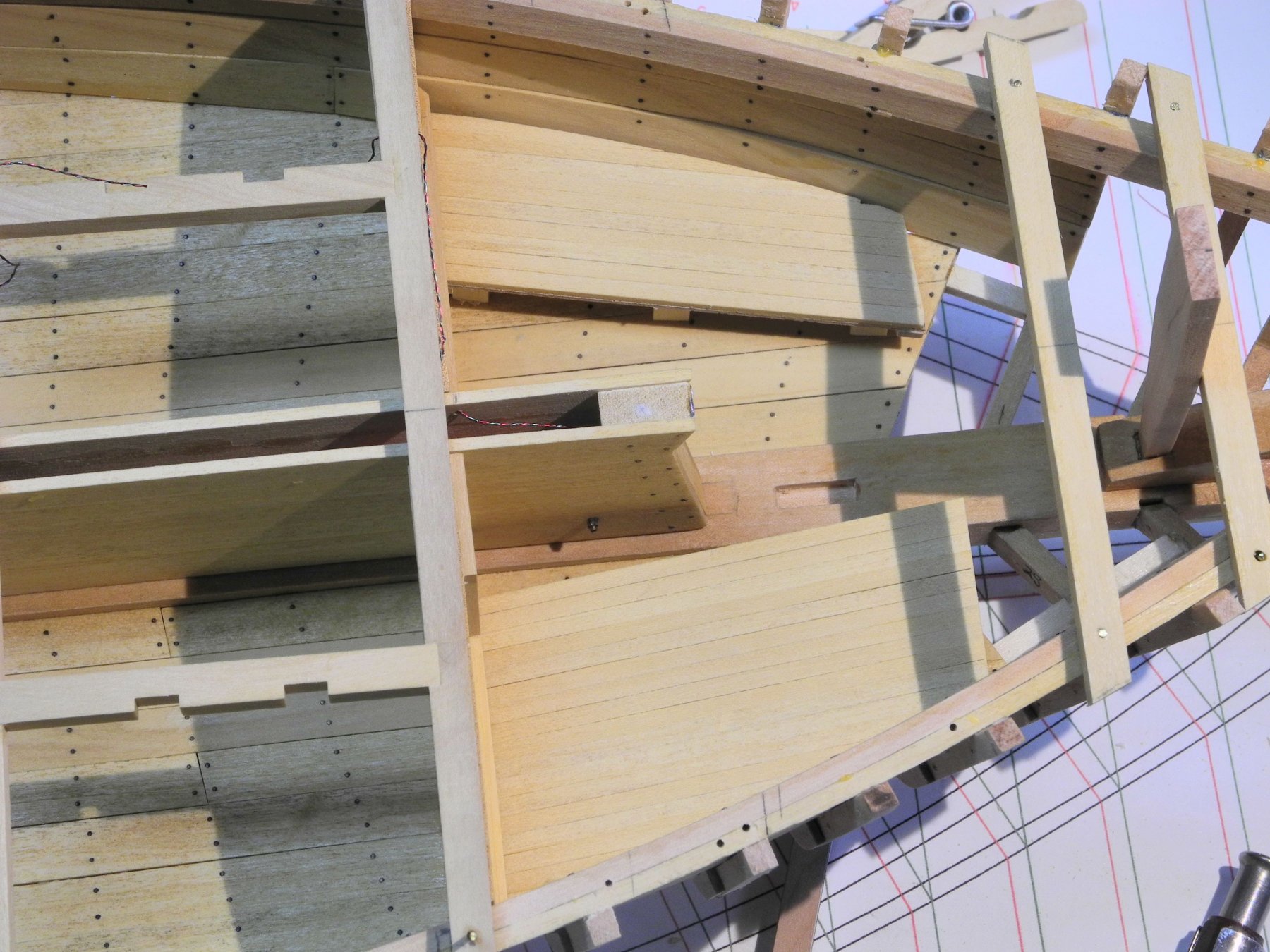
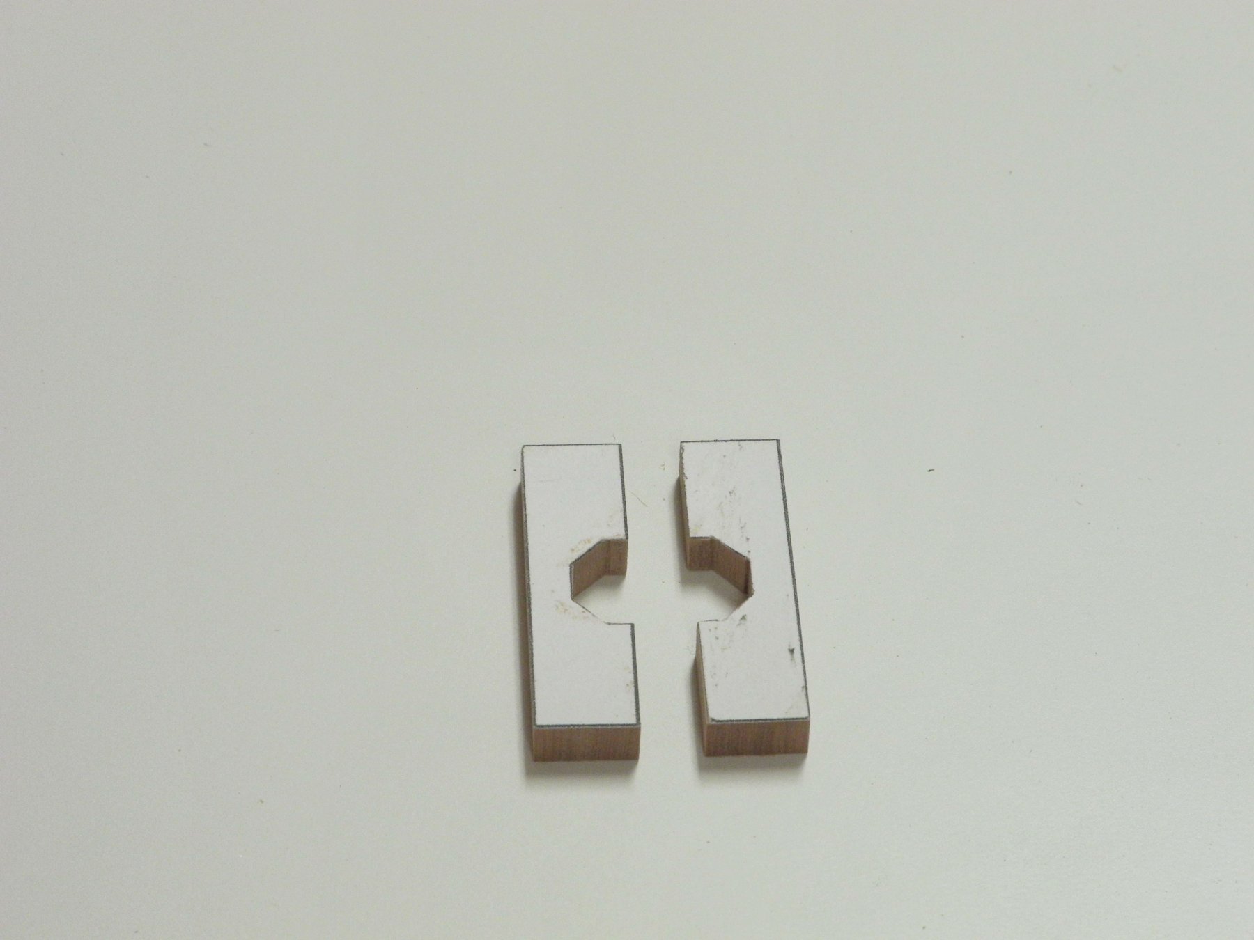
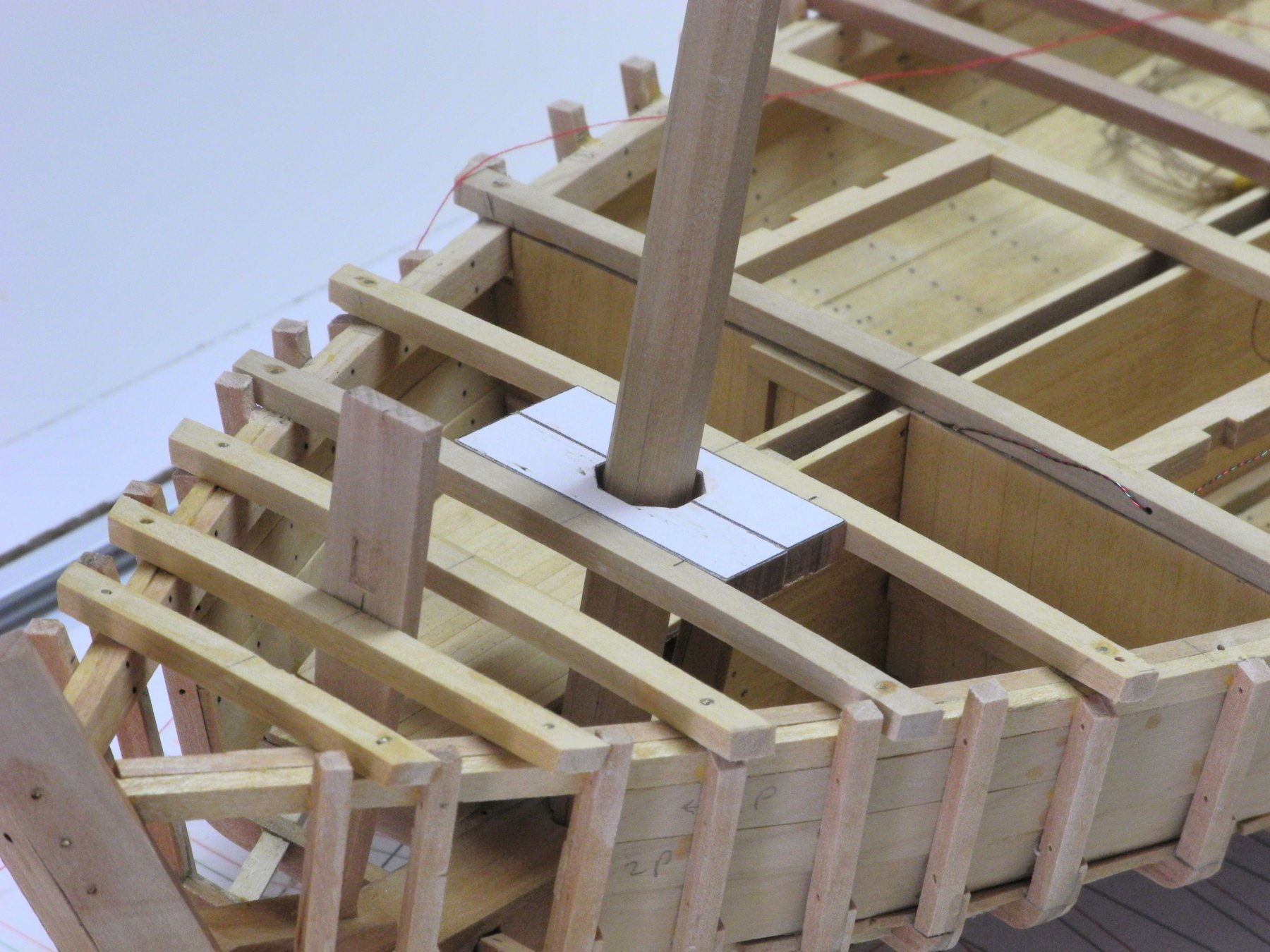
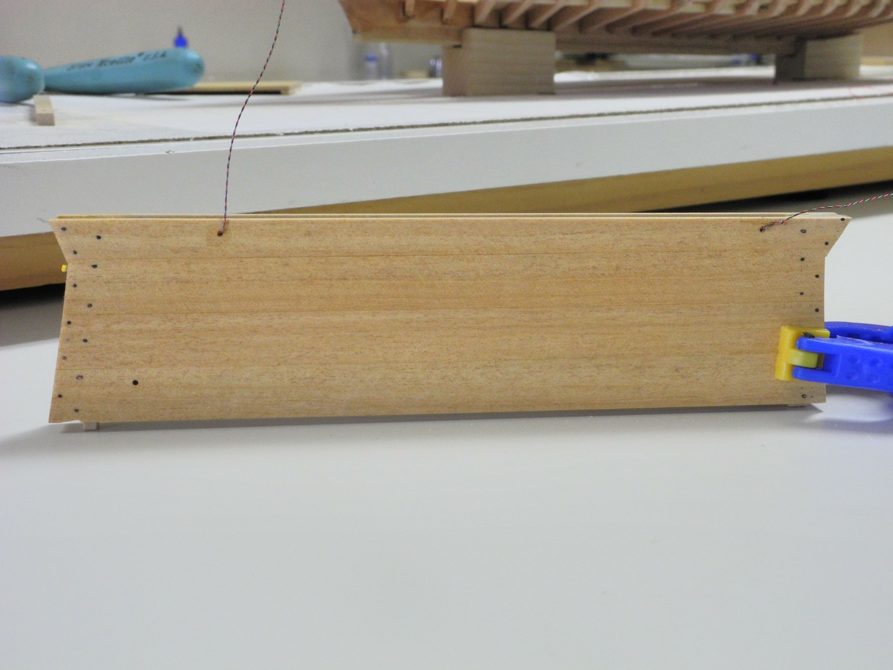
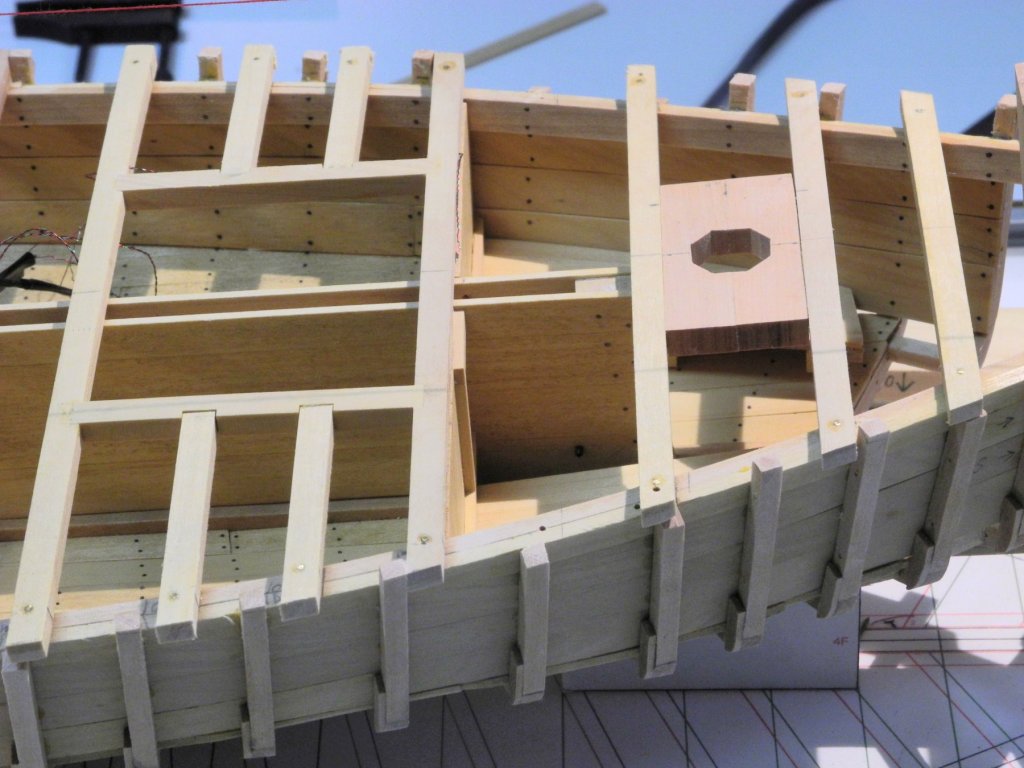
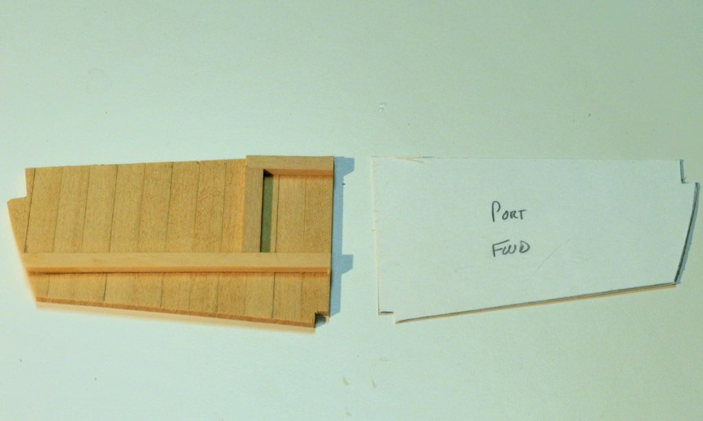
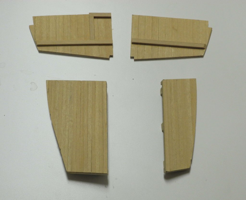
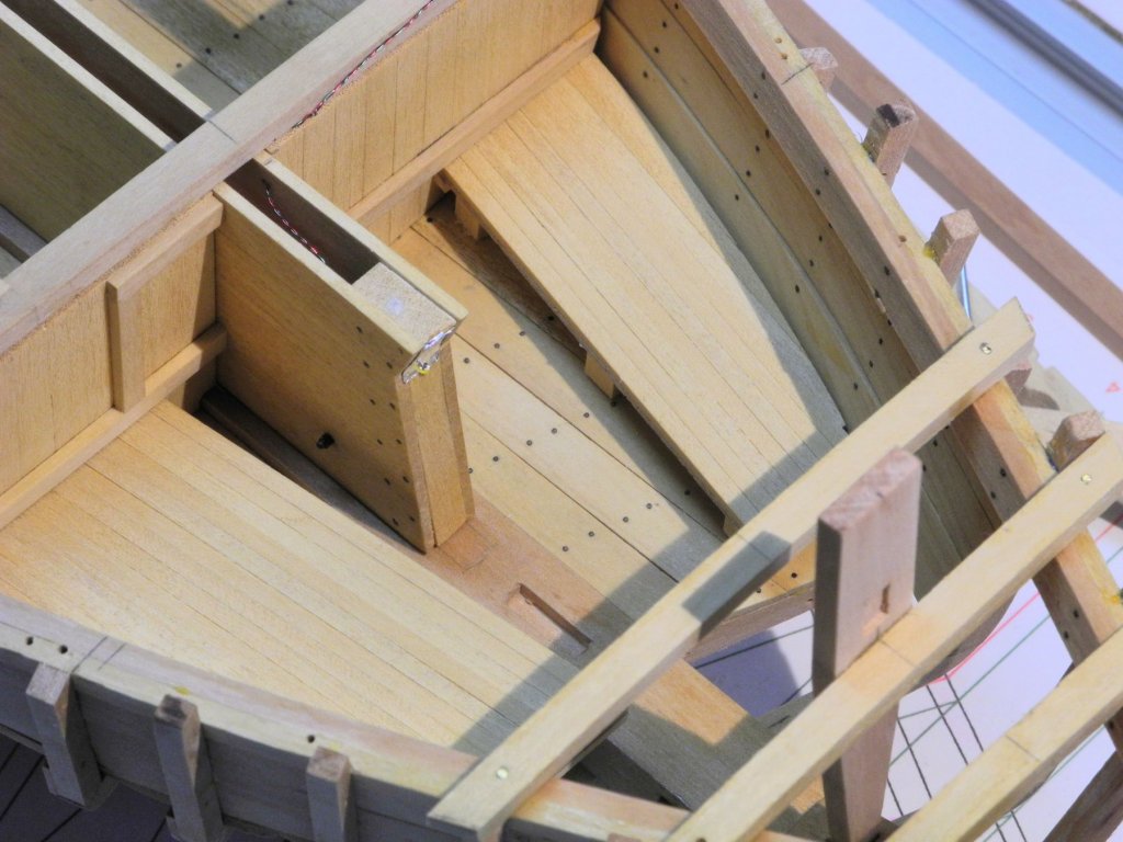
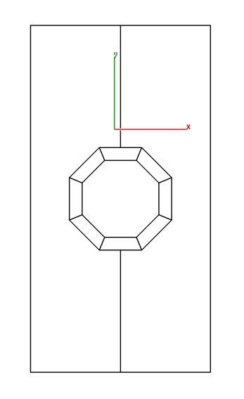
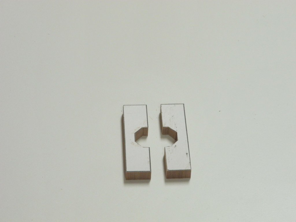
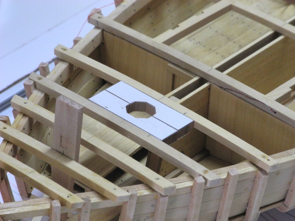
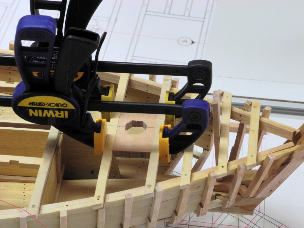
Part 20 – Bulkheads, Berths, and Partners Thanks everyone for the "Likes" and comments. Your interest keeps me interested! Once the Centerboard and Trunk were installed, it was necessary to install the deck beams for the forward hatch. There are bulkheads that are secured to the forward-most of these beams, and two forward berths are installed forward of the bulkheads. Thick card stock was used to make templates for the bulkheads. Once the templates were shaped for a proper fit, the thin slats that form the bulkheads were glued to the card stock and trimmed to fit. The following photo shows the port bulkhead as card stock, and the starboard bulkhead fully planked. The forward berths are two different widths – the port berth being much narrower than the starboard berth. These berths were part of Kathryn’s configuration at the time of the HAER survey, but when I saw Kathryn after the recent rebuild there were no forward berths. 1/32” plywood was used to make templates for the two berths, and after trial fitting to get the configuration right these templates were surfaced with very narrow planking. The following photo shows the bulkheads and berths ready for installation. The starboard bulkhead has a small passageway door framed out. This door would allow the occupants of the forward berths to pass through the bulkheads into the main hold. A small hatchway is also found in the port bow section, serving as a companionway down to the berth area. On the HAER drawings both the passageway and the companionway hatch are extremely small, so I increased their size somewhat. The passageway is still extremely small – 18” wide and 24” high. The hatch will be a similar size. The bulkheads were installed first. And then the berths were installed. After installation I realized an error I had made – I only installed the wood slats on the forward face of the bulkheads. Since the hatch covers will all be removable on the finished model, the card stock at the back of the bulkheads would show. To correct this, the individual slats on the back of the bulkheads were added one at a time, working through and around the deck beams. Mast Partners Since the section of the main mast that goes through the deck is octagonal, the hole through the mast partners needs to also be octagonal. The following drawing shows the mast partners with the hole for the mast and the wedges around the mast. The drawing was glued to the stock for the partners using a glue stick, and then the partners were cut and shaped. The partners were trial fitted to the adjoining beams, and were carefully trimmed so that the fit was tight enough for friction to hold them in place, as in the following photo. With the partners temporarily in place the mast stub was used to ensure proper placement. The partners were then glued in place and the mast stub was once again inserted to verify the partners. With this forward work completed, installation of the deck beams can continue.


- 878 replies
-
- 26
-
-
Hi Peter. Yes, I have the small jeweler's taps and dies, but I decided not to try threading the small parts. Hi Ron: The HAER drawings are from a survey done in the 1990's. Some of the documentation refers to changes that were made since she was built, but it doesn't indicate anything about the winders being changed from hand to power. Although my original intent was to model Kathryn as she was first built, I'm now modeling her as she existed when the HAER drawings were made.
-
Thanks Rich. I'm hoping to have a lot more work done by the time you get back from Ireland, although I think I'd rather be taking that trip.
-
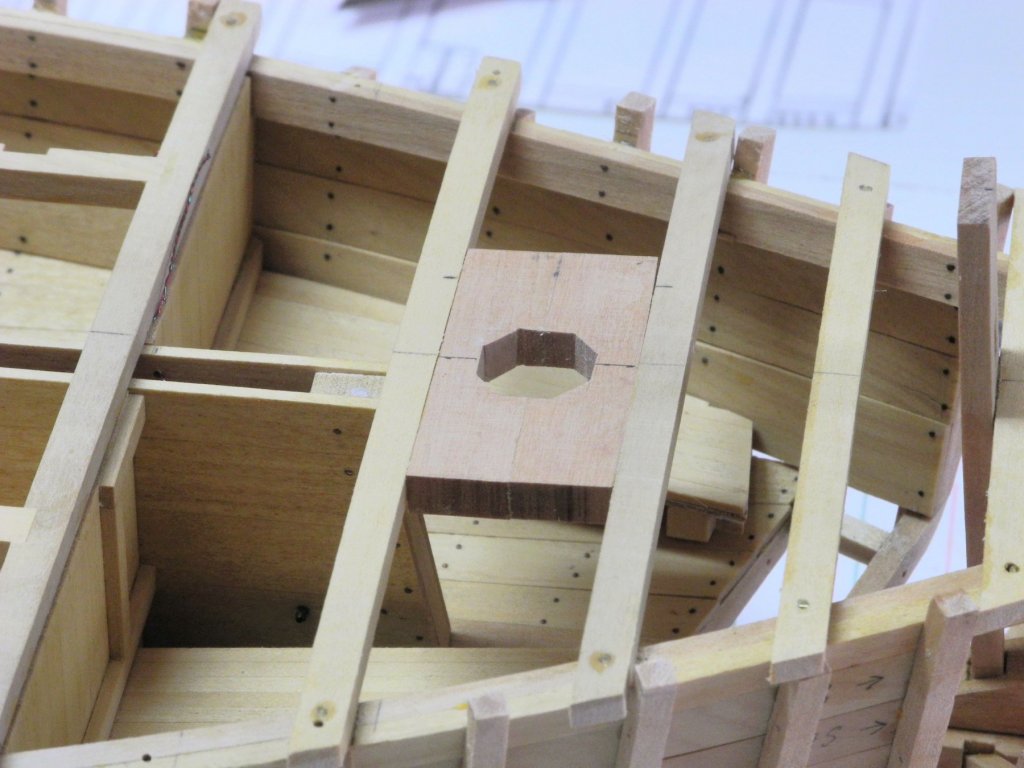
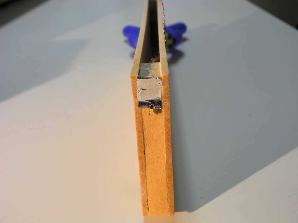
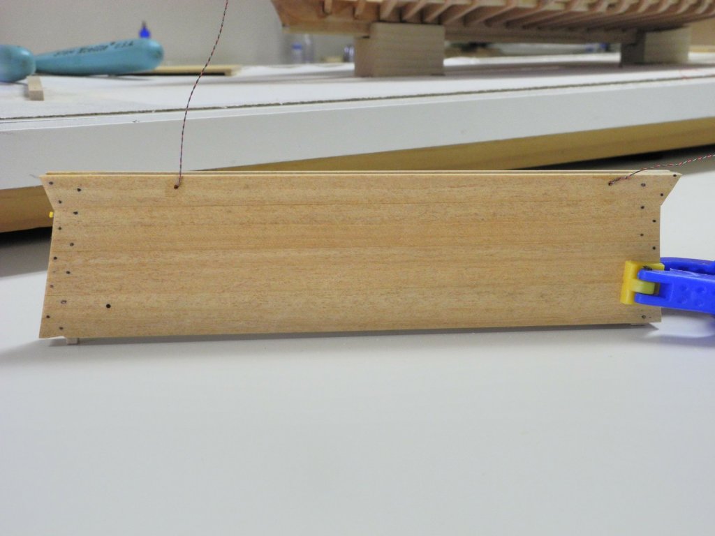
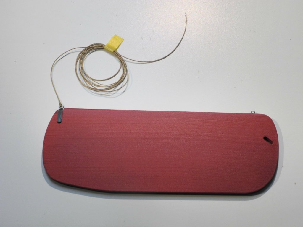
Part 19 – Installing the Centerboard At the end of the last post, I mentioned that the centerboard needed to be painted before it could be installed. Some other work was also needed prior to installation. The centerboard is held in the trunk by a pivot bolt. In some cases this is a wooden bolt, but the HAER drawings seem to show a nut on a metal bolt. In order to model this a 1/32 brass rod was used as the bolt, and a corresponding nut was made by filing the outside of a brass tube until it was square. The interior diameter of the tube is 1/32, so it made a good fit after a small piece was parted off and used as a nut. The nut was CA glued in place, since cutting a thread that small is beyond what I wanted to do. The interior of the hull will be seen through a very small hatch, so a small LED light at the front of the centerboard trunk will help to show the detail. The rear hatch will also be open, so an LED at the rear of the trunk will also help. A piece of reflective chrome tape was attached at the front and rear of the centerboard trunk where these LED’s will be positioned. The wires from the LED’s exit the trunk through holes drilled in the port side. The centerboard was painted, and a ringbolt for the hauling lanyard was installed at the rear of the centerboard. Similarly, a ringbolt was installed on the forward end of the centerboard. The forward ringbolt is only used when the skipjack is hauled out of the water and the centerboard is removed. Chappelle, in American Small Sailing Craft, gives a good description of how the centerboard is managed during that work. A hauling lanyard was attached to the rear ringbolt. I’m not sure if I will actually run the lanyard to its end location at the captain’s position, but the lanyard will be there in case I decide to do so. The following photo shows the finished centerboard. Not much, if any, of the detail will show in the finished model, but my enjoyment comes more from the building process than the appearance of the finished model. So now the centerboard and trunk has been installed, the wires for the LED’s have been run through holes bored in two frames for that purpose, and the wires have been attached to a connector for later installations. I’ve never worked with LED lighting before this, but I was able to find a web site that provides a wide range of pre-wired components that makes the job very easy. http://www.modeltrainsoftware.com/ledlights1.html Now that the centerboard trunk and the deck beams for the forward hatch are in place, the next work is to install the forward bulkhead and the forward berths. Thanks everyone, and Happy Memorial Day.

- 878 replies
-
- 15
-
-
Hi Peter - thanks for looking in. I've been able to put in some good shop time lately, so work is progressing well.
-
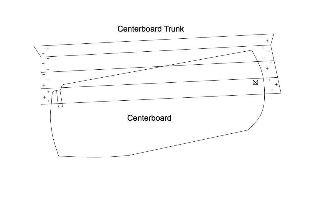
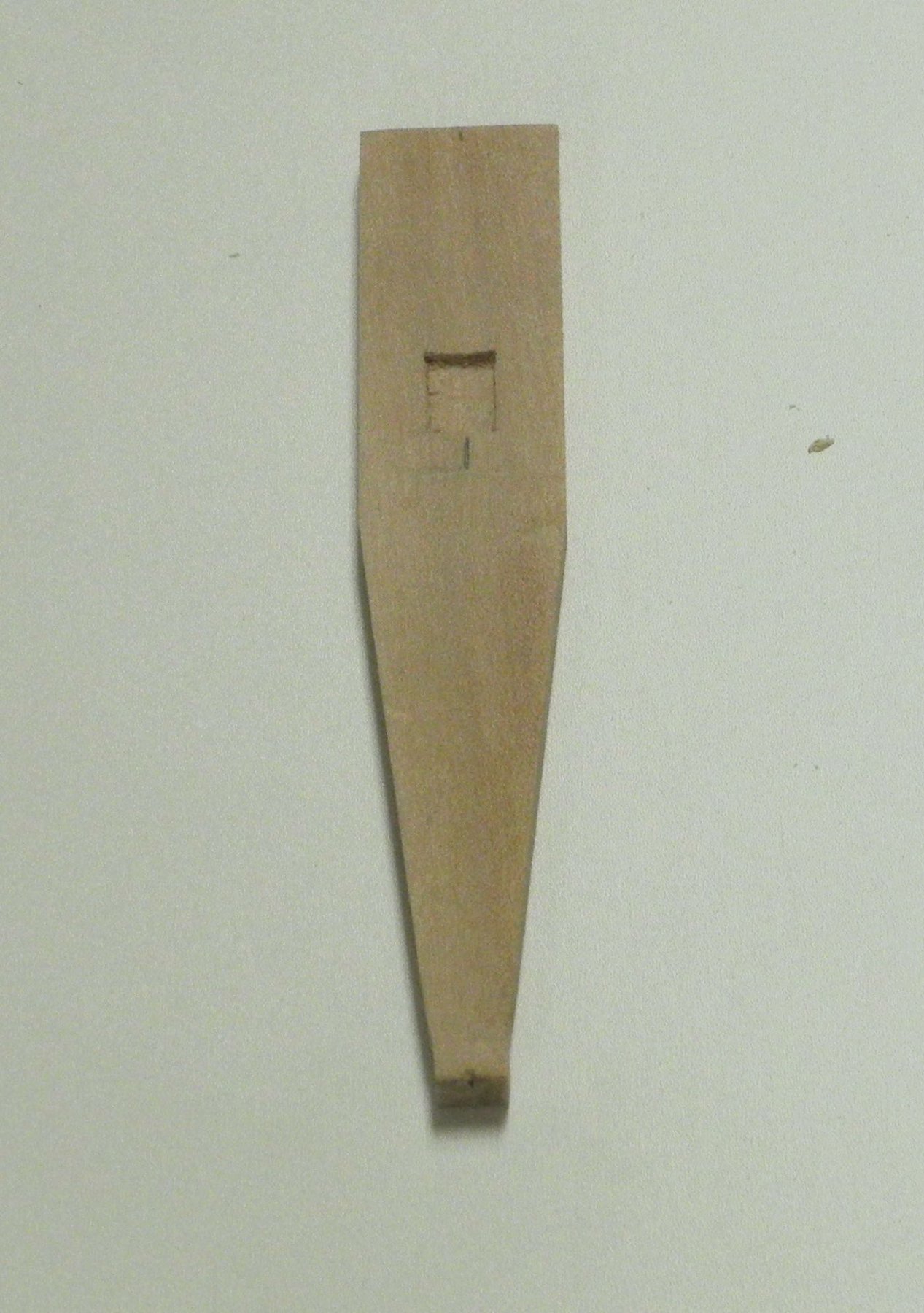
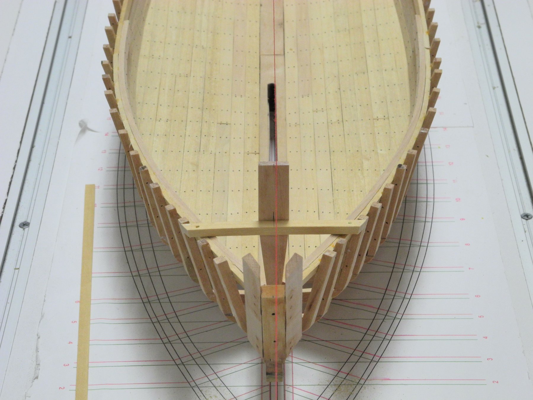
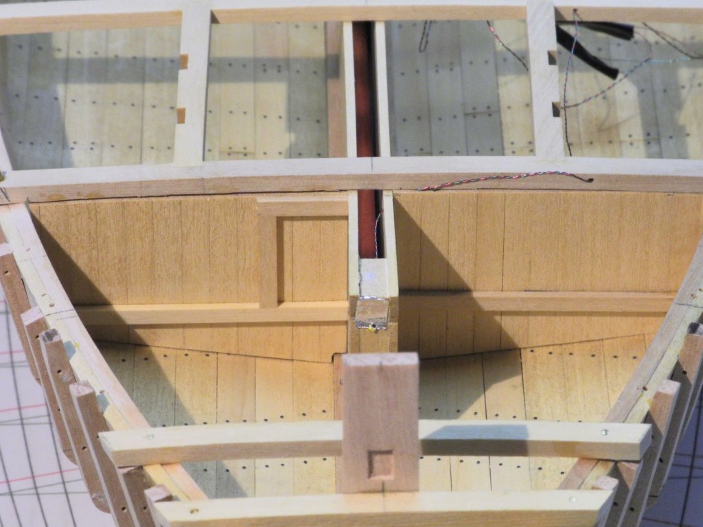
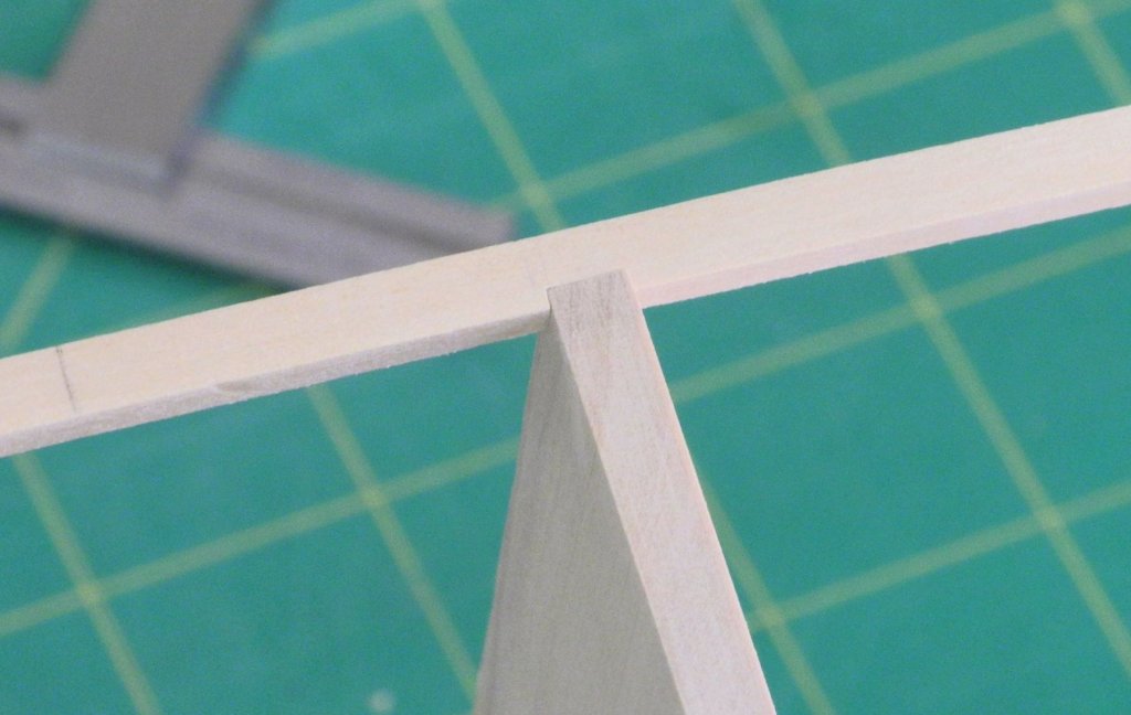
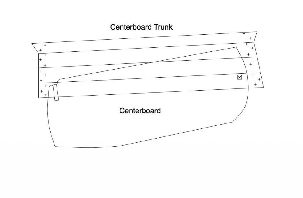
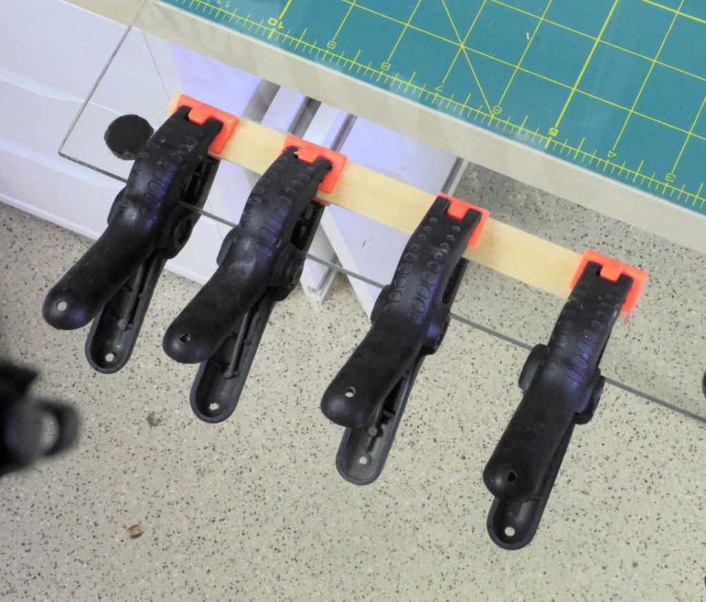
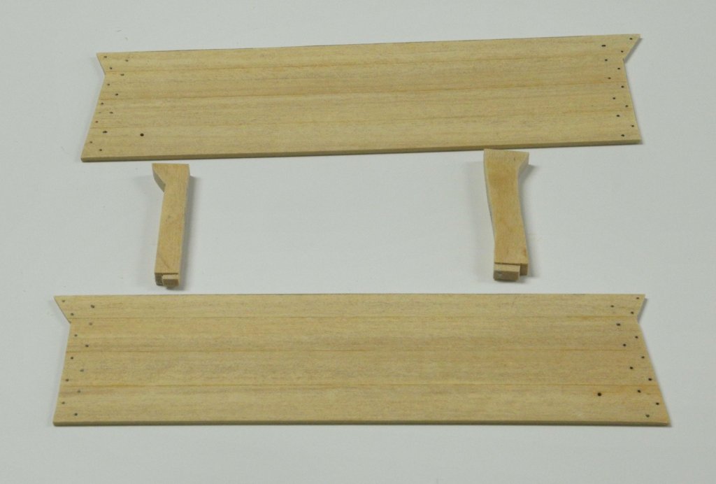
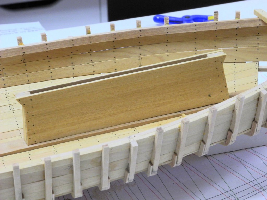
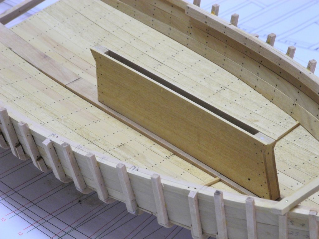
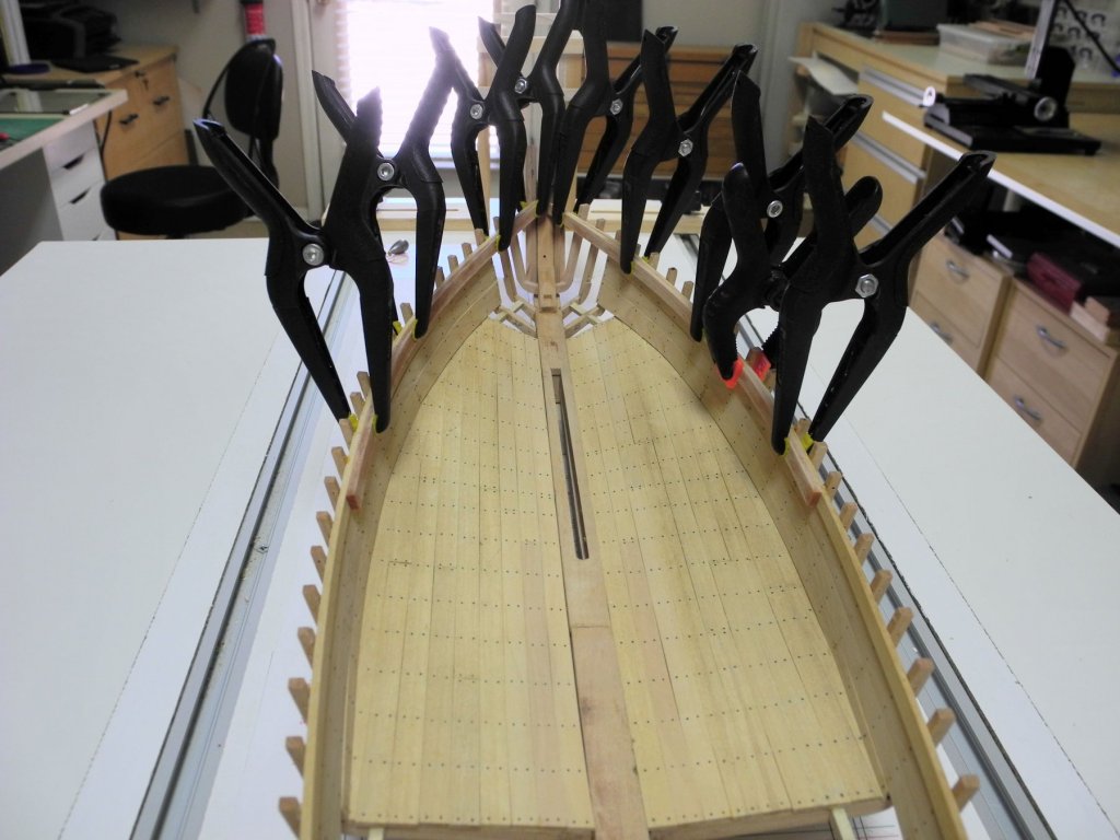
Part 18 – Installing the Deck Beams, cont’d The placement of the four deck beams associated with the forward hatch is critical not only for that hatch, but for the centerboard trunk and the forward bulkhead. The forward-most of these beams is located approximately a third of the way back from the front face of the centerboard trunk, and the forward bulkhead is secured to this beam. The bulkhead also dictates the placement of the two berths in Kathryn’s bow. The first and last of the deck beams were milled to accept the headers that define the sides of the hatch. A billet was then dimensioned to provide a tight joint between the beam and the header width, and then the billet was cut to provide enough stock for the appropriate number of Kathryn’s headers. The headers for the forward hatch were milled to accept the half beams, and then were glued to the two full deck beams for the hatch. This configuration was then temporarily installed. As can be seen in the following photos, the rearmost beam fell in the same location as a frame, so the top of the frame was trimmed back to clamp height. Battens to support the bottom of the bulkhead were installed directly below the forward beam of the hatch. The Centerboard Trunk was then constructed based on the following drawing (adapted from the HAER drawings) The side planks for the trunk’s two sides were edge glued, clamped to a piece of plate glass to ensure that they remained flat. When the glue joining the initial two planks cured, another plank was added, and then another as the fourth and last plank for the side. The process was repeated for both sides of the trunk. The two sides were then were marked for cutting using the trunk drawing on a piece of card stock. The end posts of the trunk were cut from a piece of stock, based on the bolt configuration shown in the HAER drawing. The small tabs seen on the bottom of the posts were left to ensure proper location of the trunk related to the centerboard slot. The centerboard of a skipjack is fitted so that, when hauled up, they extend some distance below the keel, but if an obstruction is hit, the board can rise in the trunk. In order to allow this, the centerboard and has a slanting slot rather than a hole for the pivot bolt. The following photo shows the centerboard (without mounting hardware) and the trunk fully assembled. The following photos show the centerboard and trunk temporarily in place. The hatch beams were temporarily installed to check the height of the trunk. Some minimal shaping was required for a proper fit. The Sampson Post shown in the prior post had a flat forward face. I was unable to find any clear photos of how the end of the bowsprit fitted against the Sampson Post. However, when a bowsprit butts against a single Sampson Post, I believe it’s normal to have a mortise cut in the face of the post and for a small tenon to be cut into the rear of the bowsprit – ensuring a tight fit that will not allow the bowsprit to shift. I decided to cut a 4-inch wide mortise into the Sampson post, beginning approximately 1 inch above deck height. The mortise would mate with a 4-inch square tenon on the bowsprit, and the mortise height of 6 inches would allow some flexibility in setting the angle of the bowsprit. The mortise was cut using a 1/8” chisel. The Sampson Post was then glued in place. This brings us to where Kathryn stands today. The centerboard will need to be painted before it can be installed, since removing it for painting later in the build will not be possible. I’m trying to find an appropriate color to use as anti-fouling red. A friend who has built many Chesapeake Bay workboat models recommends the use of Liquitex Burnt Sienna – I’m going to give it a try. Thanks everyone!


- 878 replies
-
- 21
-
-
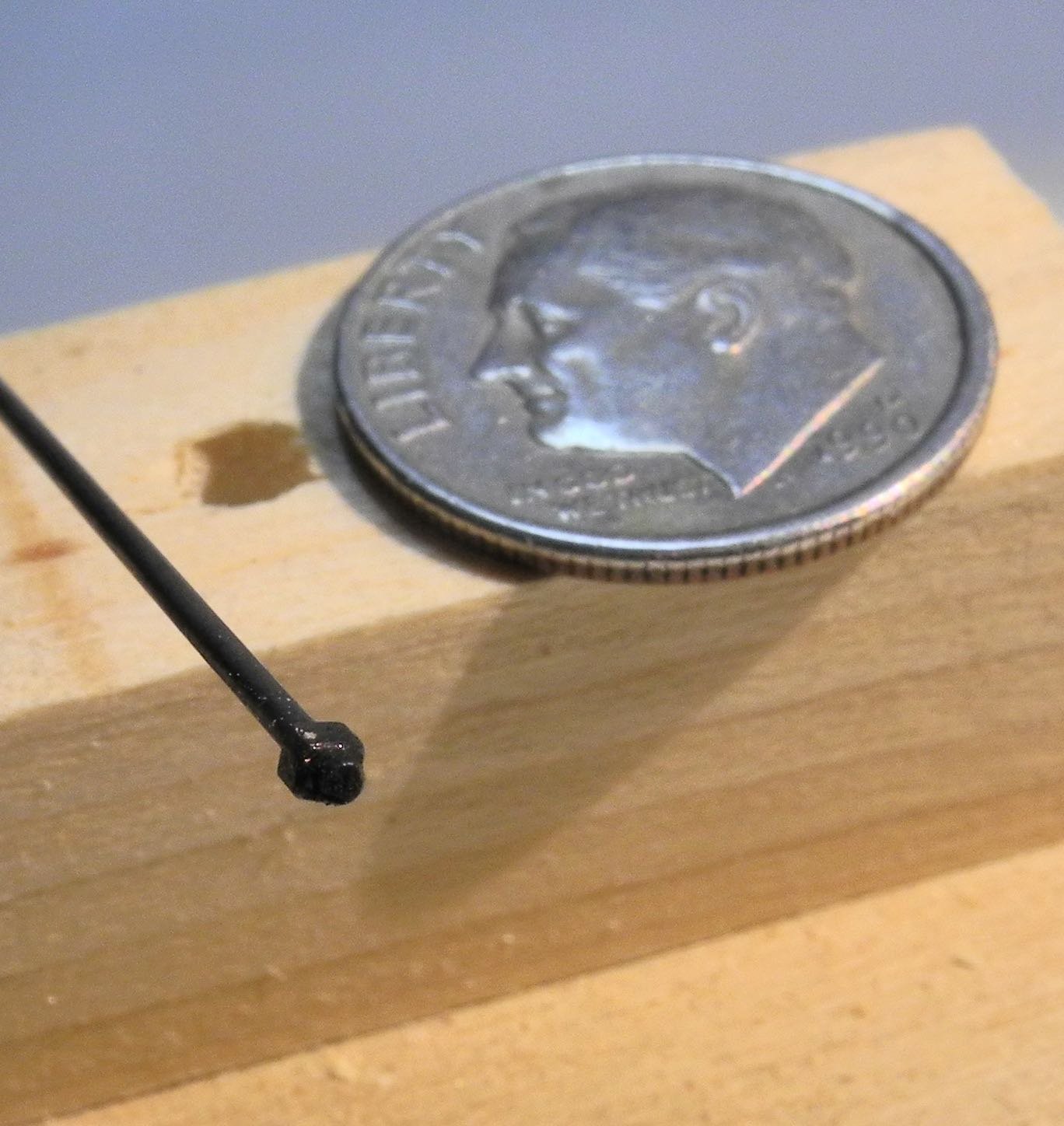
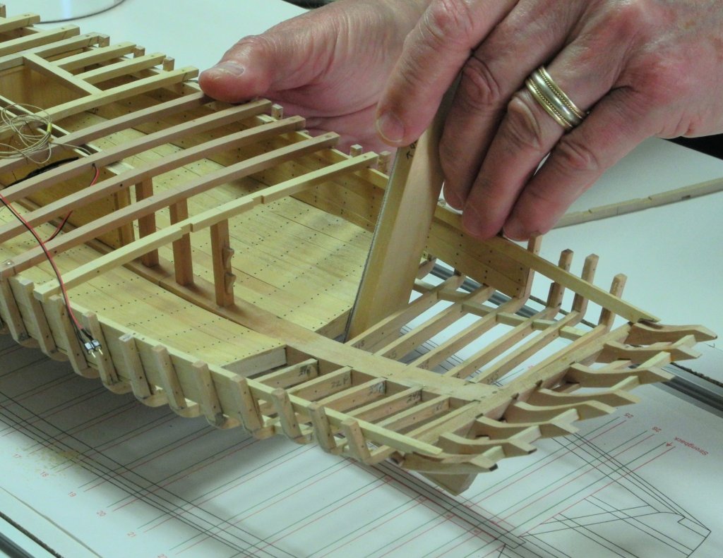
Are you planning on putting little supermodels on your super model? Wow, the photo of the chaise on your finger really brings home the scale you're working in. Great work!
-
Thanks Nils. Yes, the centerboard will pivot. Installation of the centerboard will be covered in the next post.
-
Hi Patrick - always great to hear from you. The only stupid question is the one that wasn't asked. HAER stands for Historic American Engineering Record, which is a service from the Library of Congress. It contains detailed surveys on a large number of topics - nautical information is only a part. The documentation on Kathryn includes 8 pages of drawings that resulted from a survey performed in the mid-90's (available as JPG's or high-density TIFF files) as well as a number of actual photographs and the documentation supporting Kathryn's nomination as a National Historic Landmark. Here's a link to the section on Kathryn, in case you'd like to see the details. http://www.loc.gov/pictures/collection/hh/item/md1454/ I plan to paint Kathryn's exterior (she's mostly white above the waterline), and to leave the interior natural (will probably put on some wipe-on poly to preserve it). The interior of the cabin seems to be stained, so I'll try to emulate that. Most of the interior work will be covered up - I'll probably leave the hatch covers off and maybe a few deck planks and I'm thinking of making the cabin roof removable, but the interior work is mostly for my enjoyment and will only be seen in photos once I'm done. I do plan to put a little lighting belowdecks but I'm not sure how much it will show. All the best,
- 878 replies
-
- 10
-
-
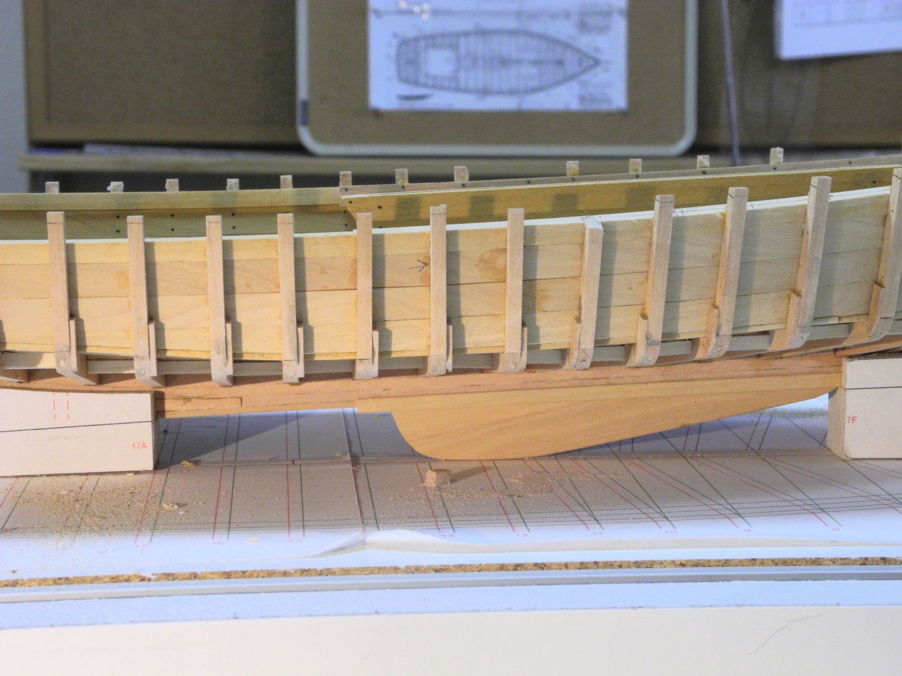
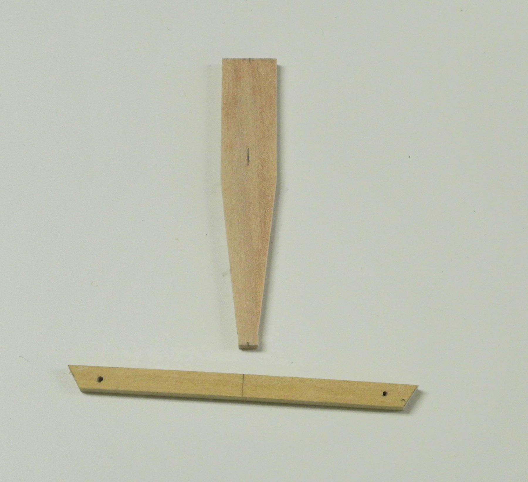
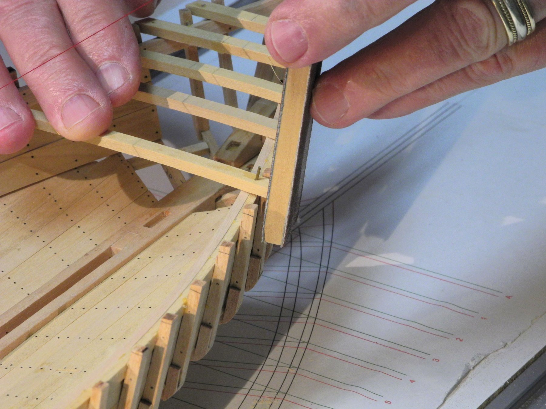
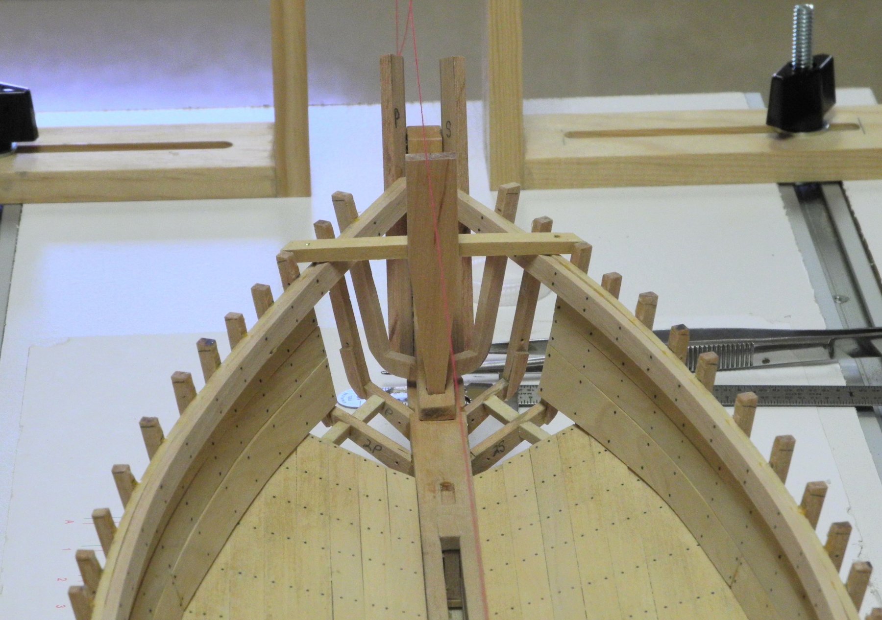
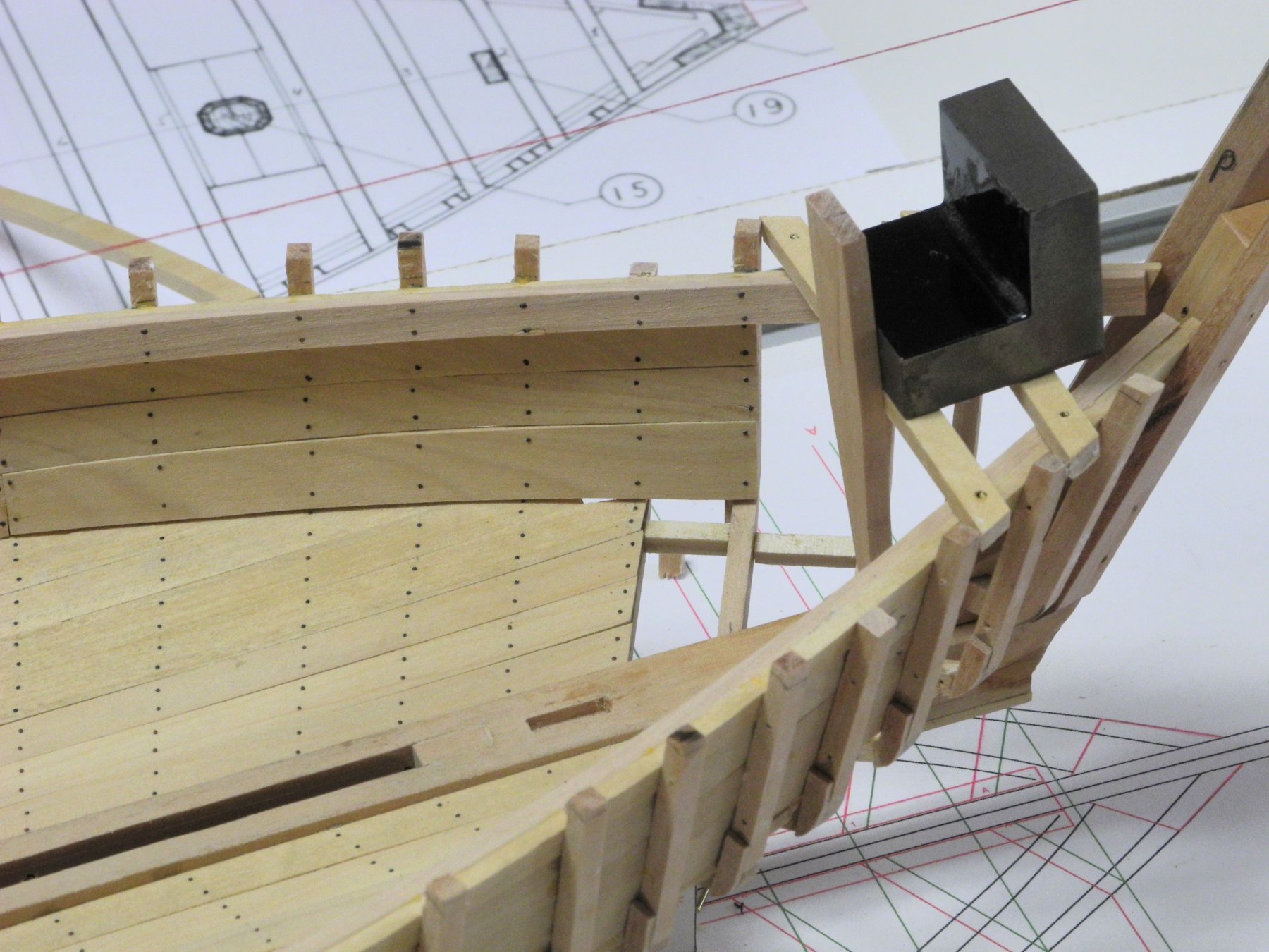
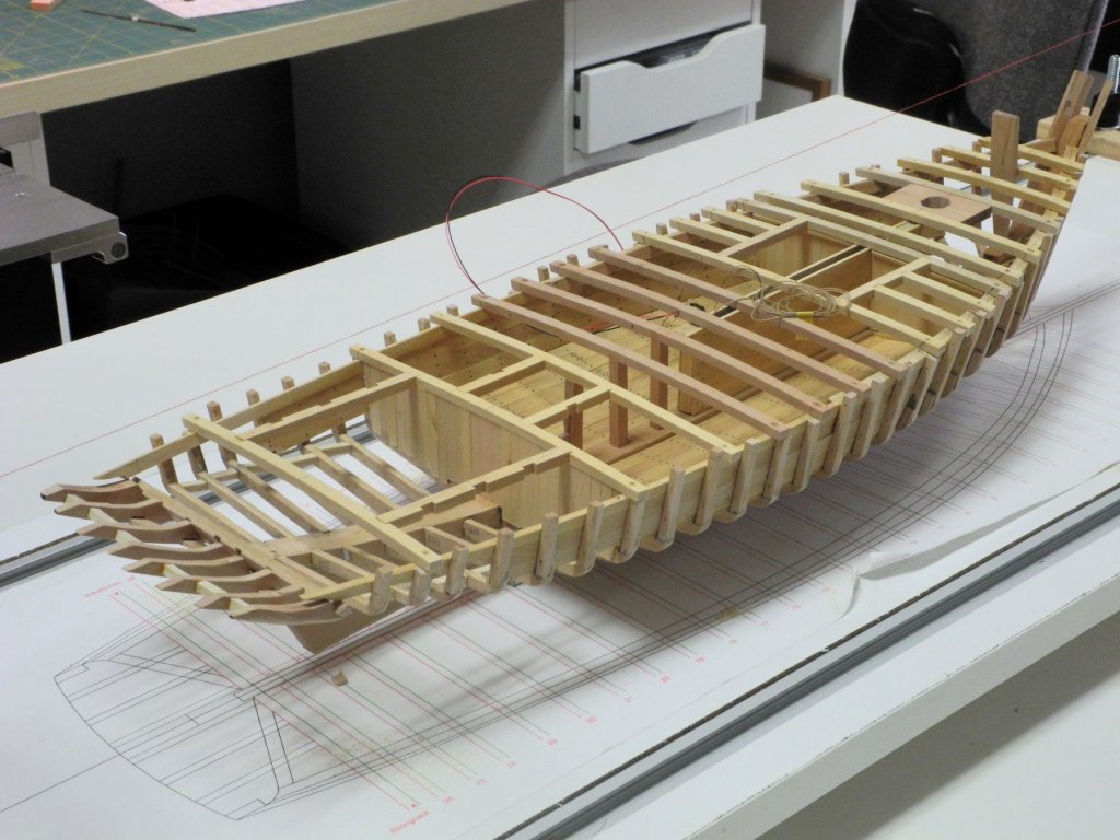
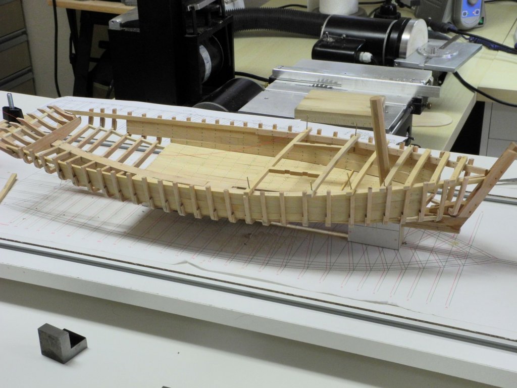
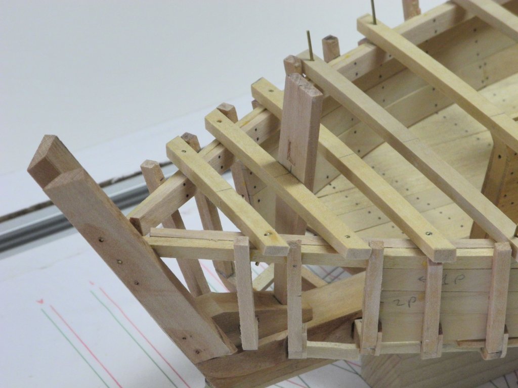
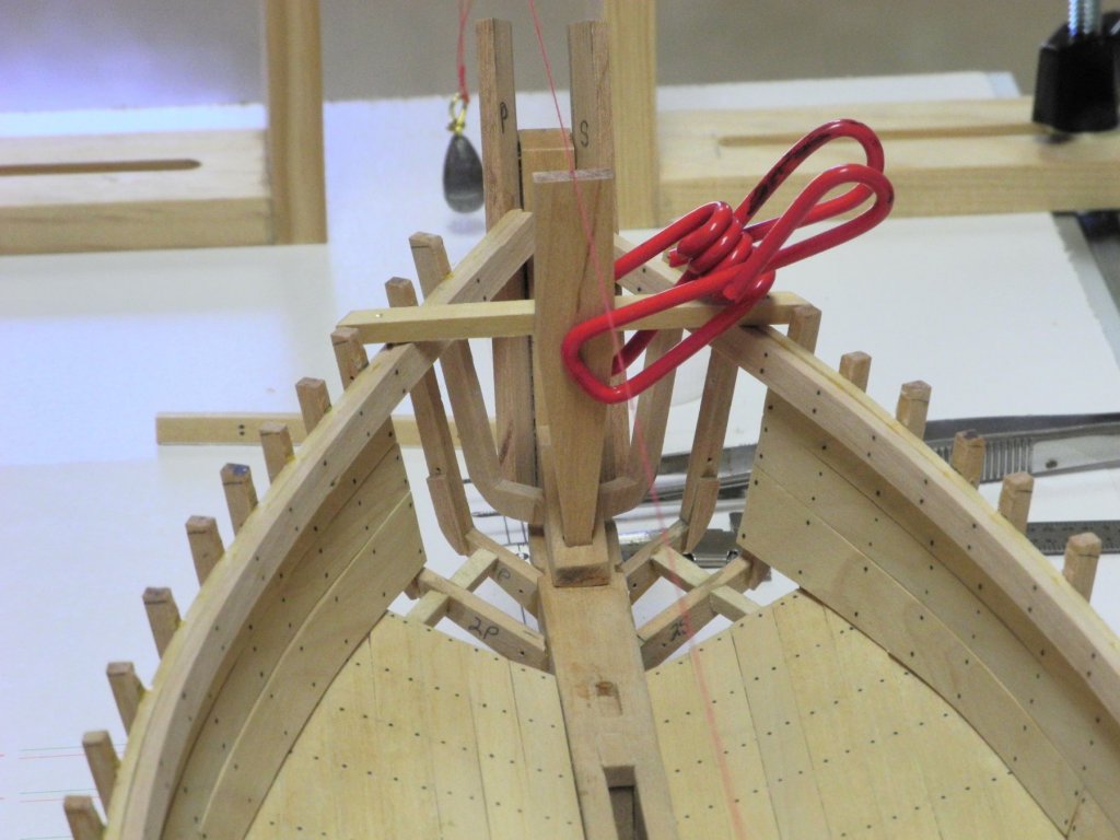
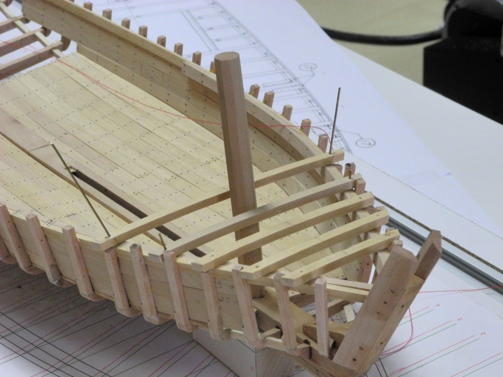
Part 17 – Installing the Deck Beams The next step is to install the deck beams. The stern appears to be too high, and this was confirmed by test fitting the rearmost deck beams. Before proceeding with the deck beam installation, the stern was removed and refitted. Two deck beams were temporarily clamped in place, and two deck planks were attached using wire ties. Two bottom planks were also wire tied to the frames. These planks were used to ensure that the stern timbers were set at the correct height and angle, and then the stern was glued back in place. The view of the deck beam layout from the HAER drawings was printed at the correct scale, and was used as a guide for the installation of the deck beams. As a preliminary check, all deck beams were laid in the appropriate locations. It became clear that some of the frames would need to be trimmed back to the height of the clamp, since some of the deck beams would be in the same location as the frames. Some of the beam locations are critical, since they determine the location and rake of some components. The first of these is Beam 2, which supports the Sampson Post. The Sampson Post, made of oak, is 5” thick, and tapers from a 5” width at the keelson to 1’-2” at deck height. Above the deck it is consistently 1’-2” in width. Deck Beams are glued to the clamp, but are also strengthened by functional bolts made of 1/32” brass rods that tie the beam to the clamp. Deck Beam installation consists of 1. Locating the beam along the clamp 2. Centering the beam by aligning the centerline drawn on the beam with the centerline thread 3. Locating and drilling the holes for the brass rod through the beam and into the clamp. 4. Glueing the beam to the clamp with PVA glue 5. Glueing the functional bolts using medium-viscosity CA glue 6. Trimming (fairing) the beam ends The initial deck beam (Beam #2) is being glued in place. It was then bolted and faired, as in the following photo of a later beam being faired. The Sampson Post was then tacked in place. It was not permanently installed at this time since there was still an open question on the Sampson Post – which will be discussed in a later post. When Beam #2 was completed, Beam #1 was installed approximately halfway between #2 and the stem. The next critical beam was the forward-most of the beams adjacent to the mast (Beams #4 and #5), so Beam #3 was installed at the nearest frame. The following photo shows the first three beams permanently installed, with Beams #4 and #5 held in place temporarily be brass rods. A stub mast was used to verify the placement of beams #4 and #5 The stub was left as an octagonal since the full mast will remain octagonal when it goes through the deck to the keelson. Details on the construction of the mast will be provided when the full mast is described in a later post. The next post will address the construction of the beams for the forward hatch, the Centerboard Trunk, and revisions to the Sampson Post. Thanks Everyone!


- 878 replies
-
- 23
-
-
Thanks Druxey. I've tried rubber cement, but prefer glue sticks. Thanks Brian - our meetings are always interesting. And they make me clean the shop at least once a month!
-
Hi Dan - thanks for the comments. Your point on positioning the bolts is interesting. I hadn't thought of this, so I checked some photos of Kathryn's recent reconstruction, and this confirmed your comment. Even though the frames are only 4 inches wide the bolts are staggered slightly. I don't think at this point I'll try to correct the bolting pattern - that would mean starting over! Very little of the interior work will show on the finished model, and all of the exterior will be painted so I won't be doing much simulated bolting on the exterior. Thanks very much for pointing this out. When (if) I do another model this way I'll certainly plan to do it correctly.
-
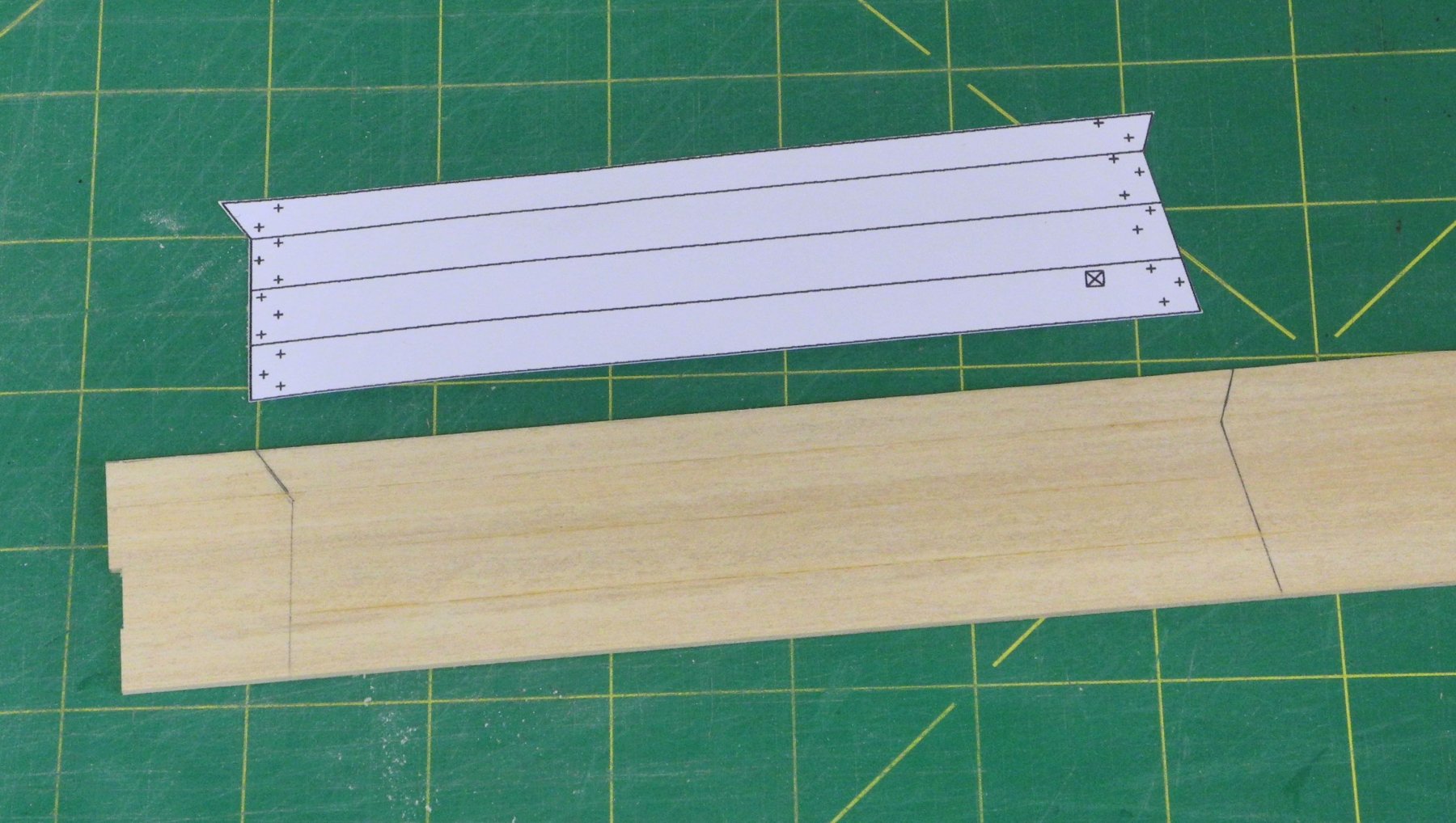
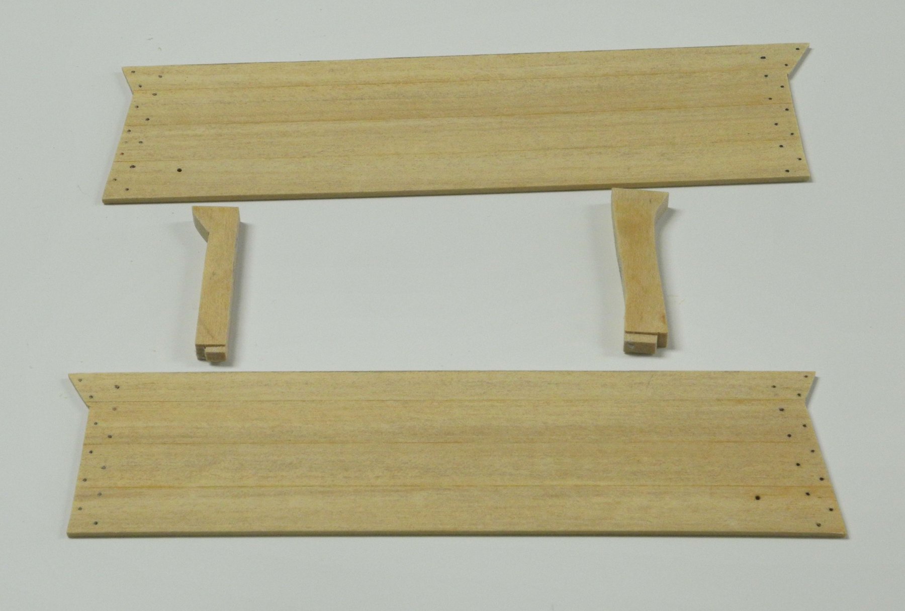
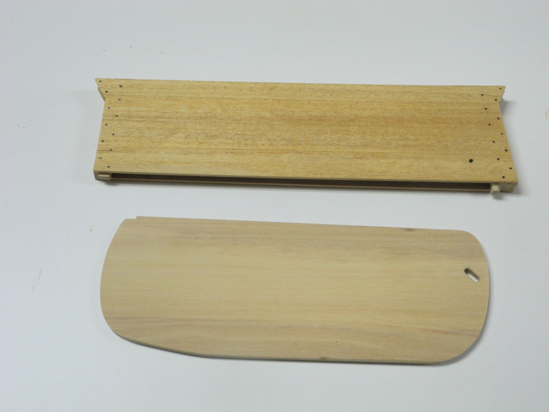
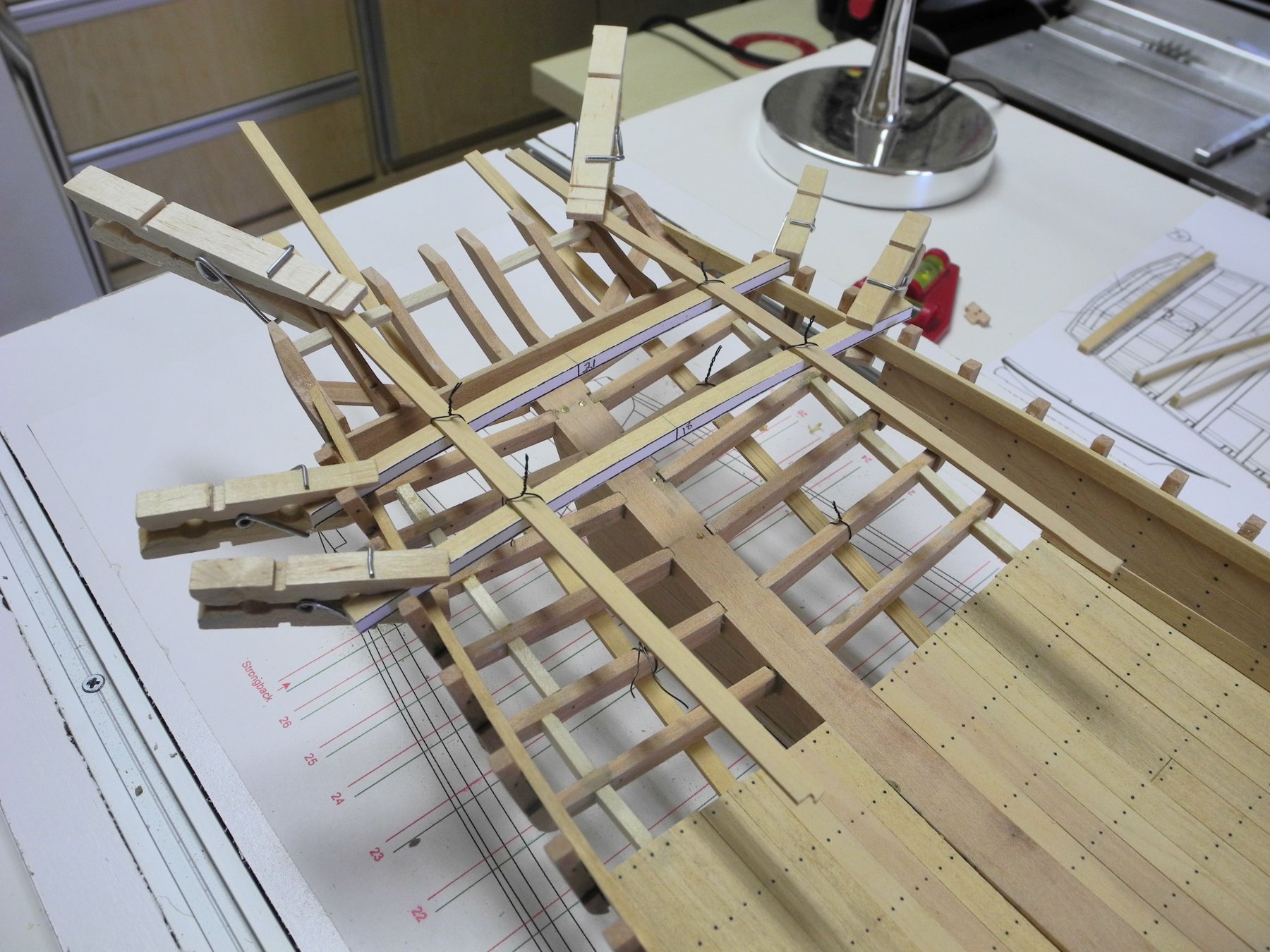
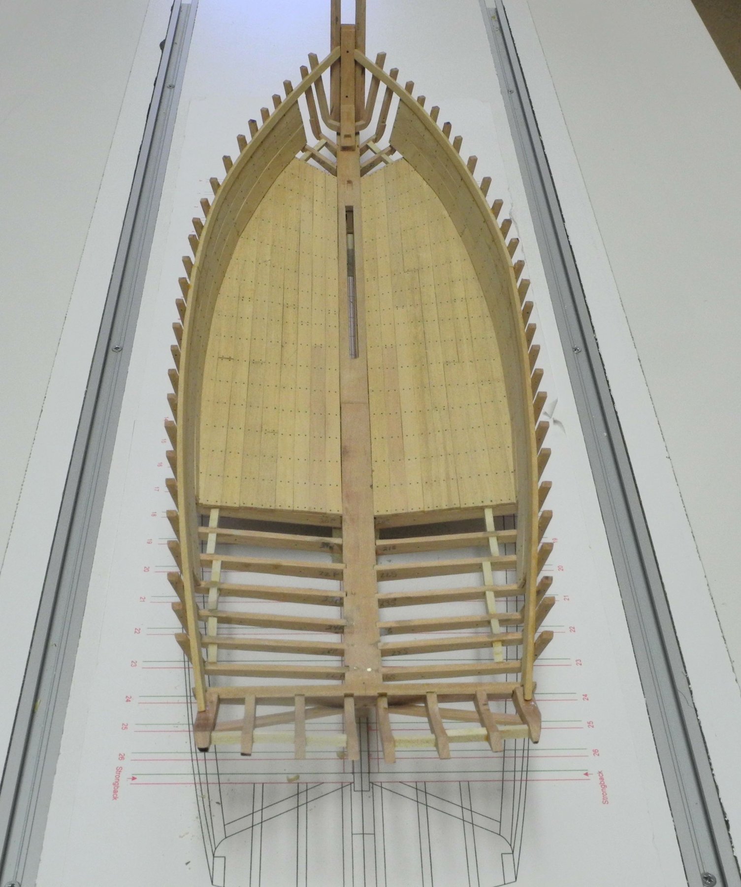
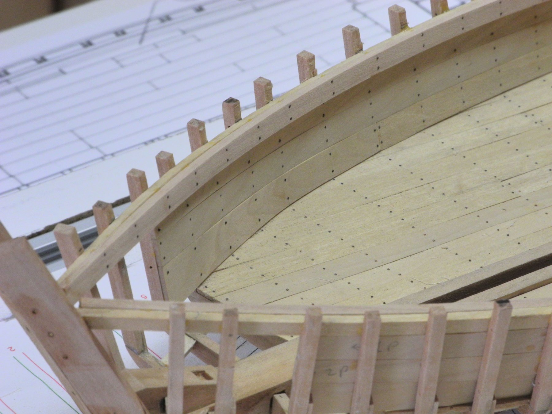
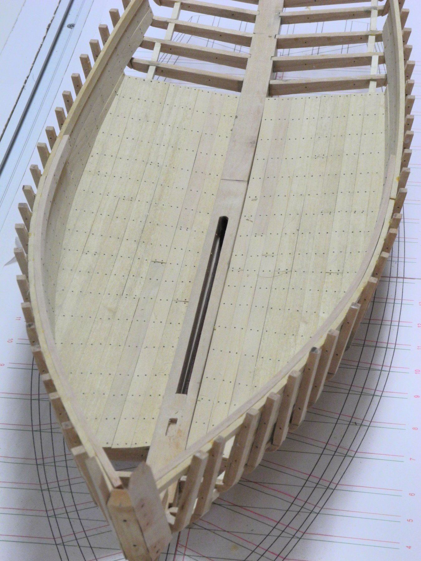
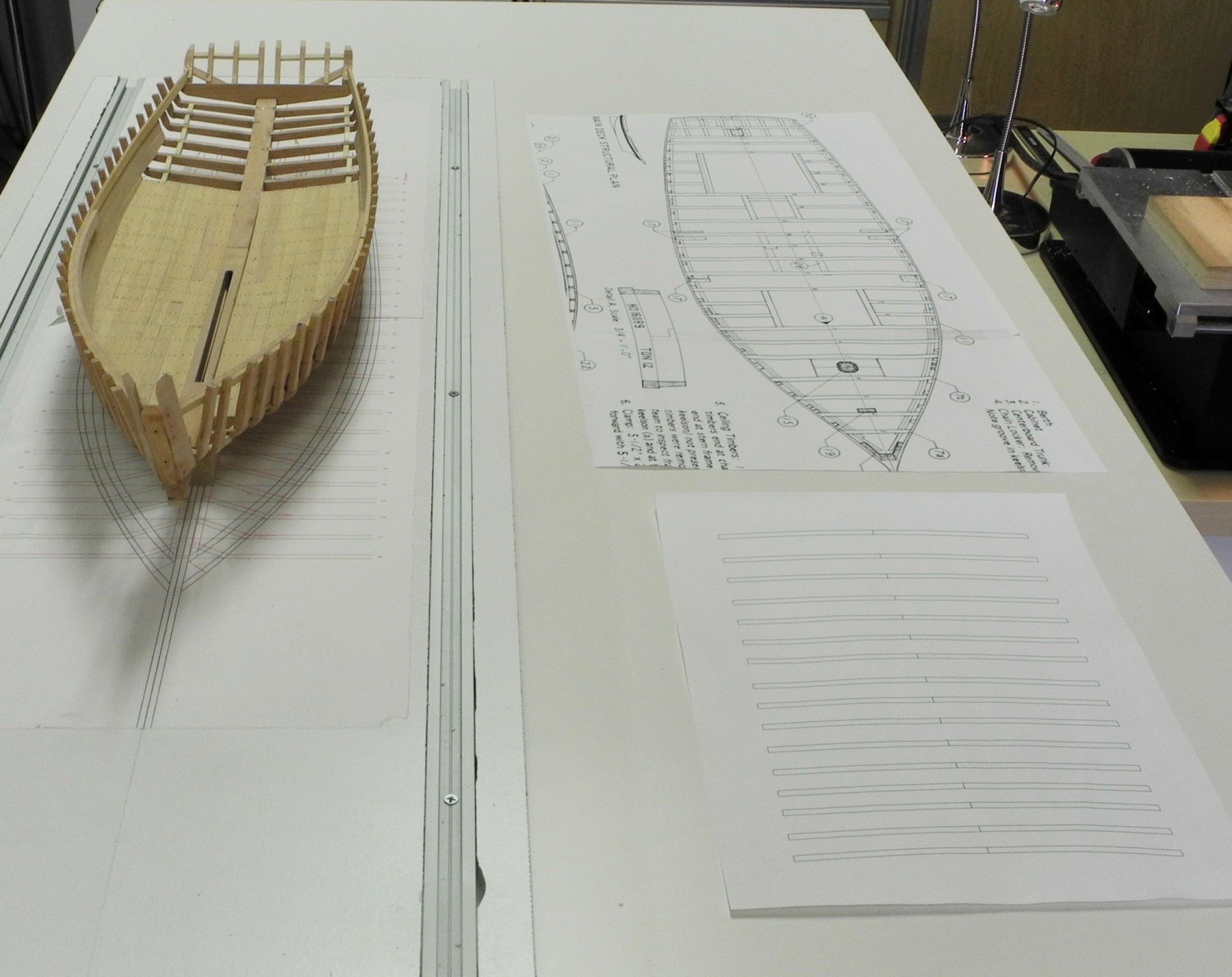
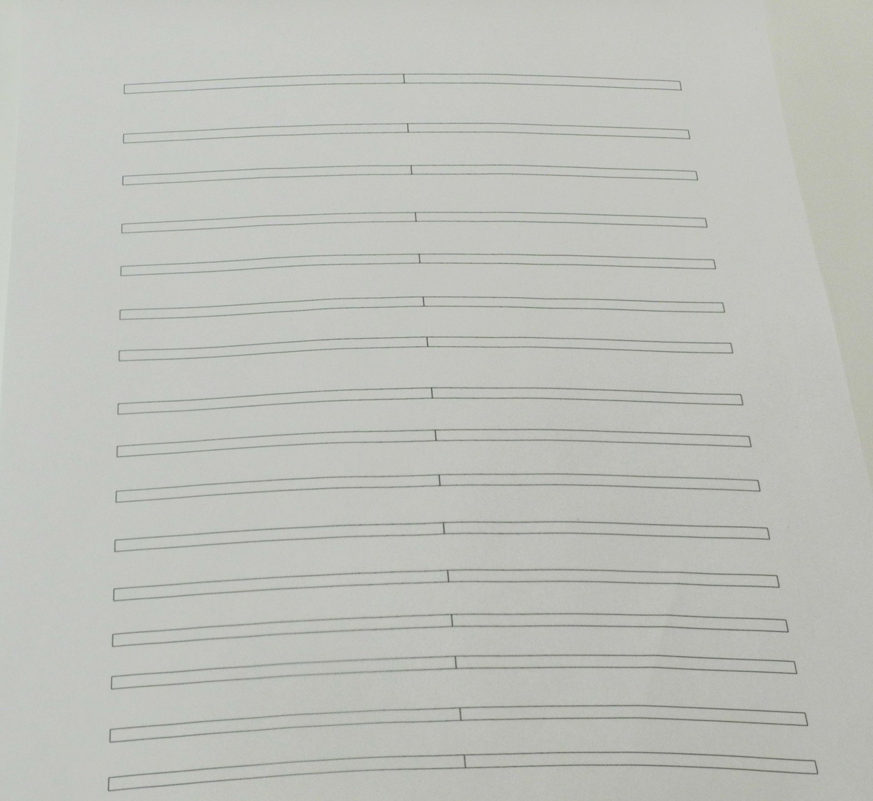
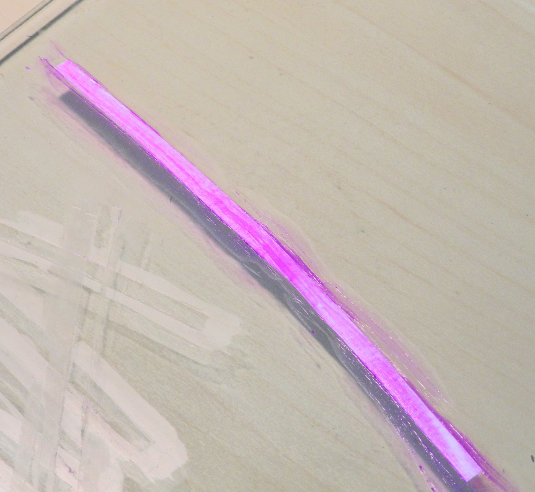
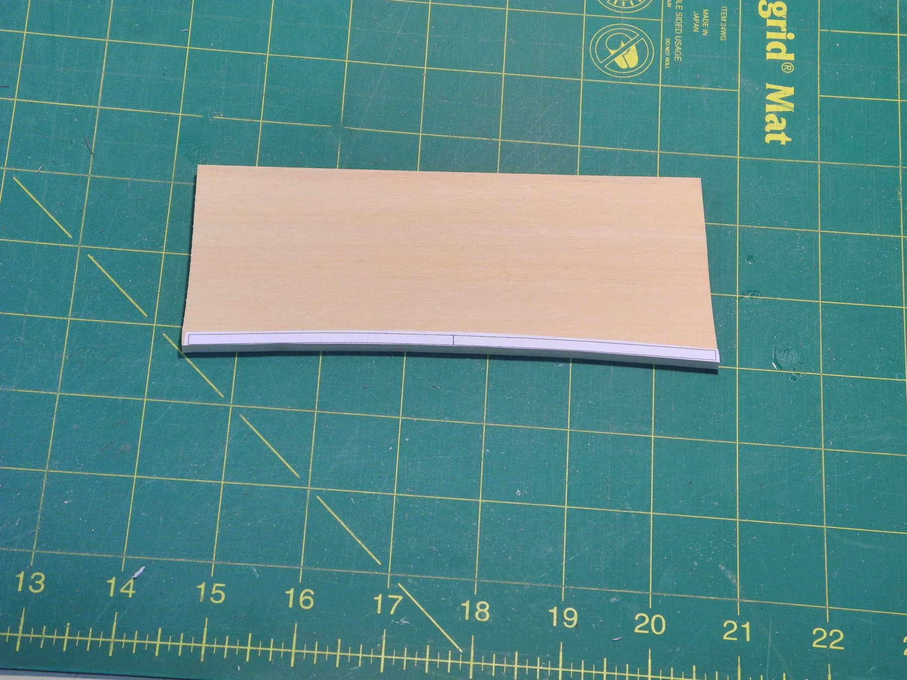
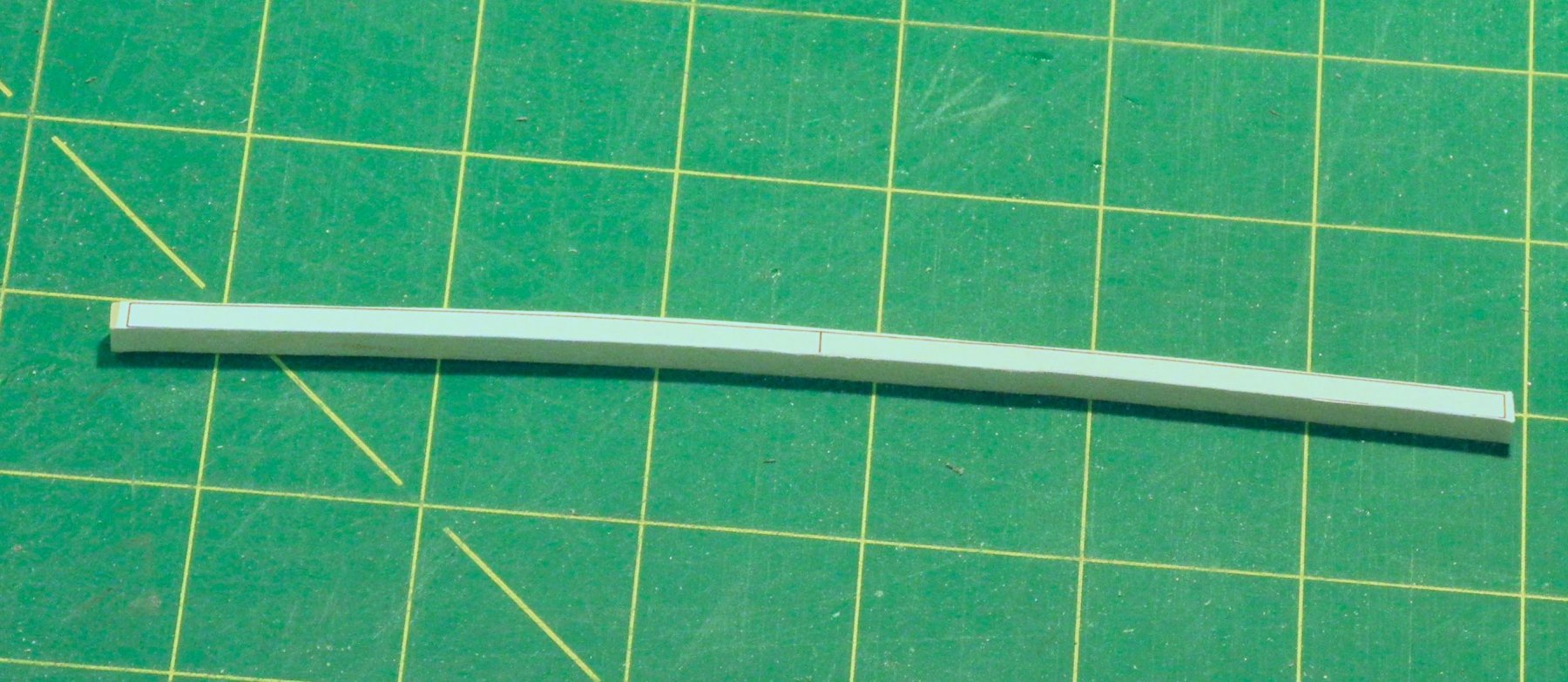
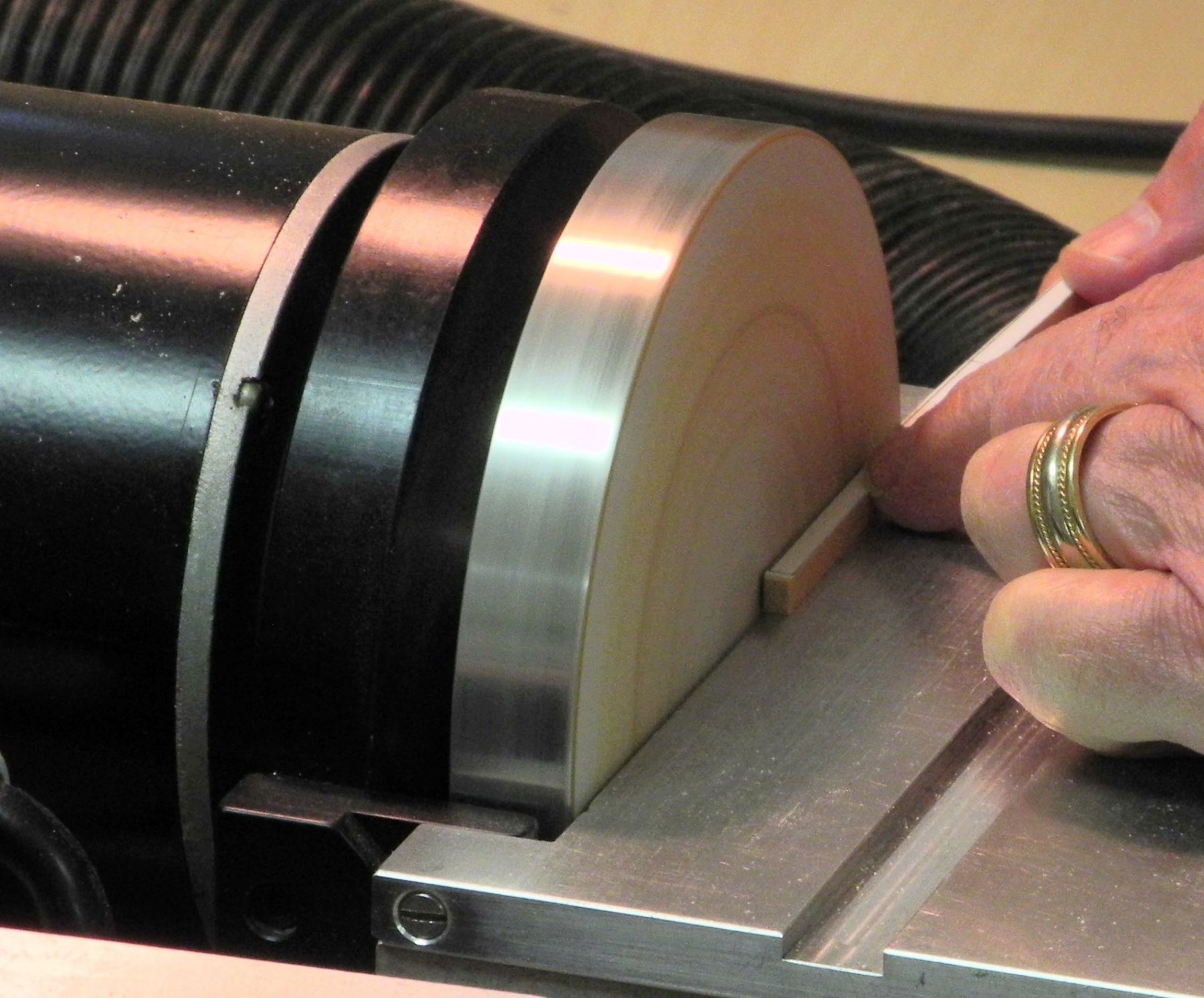
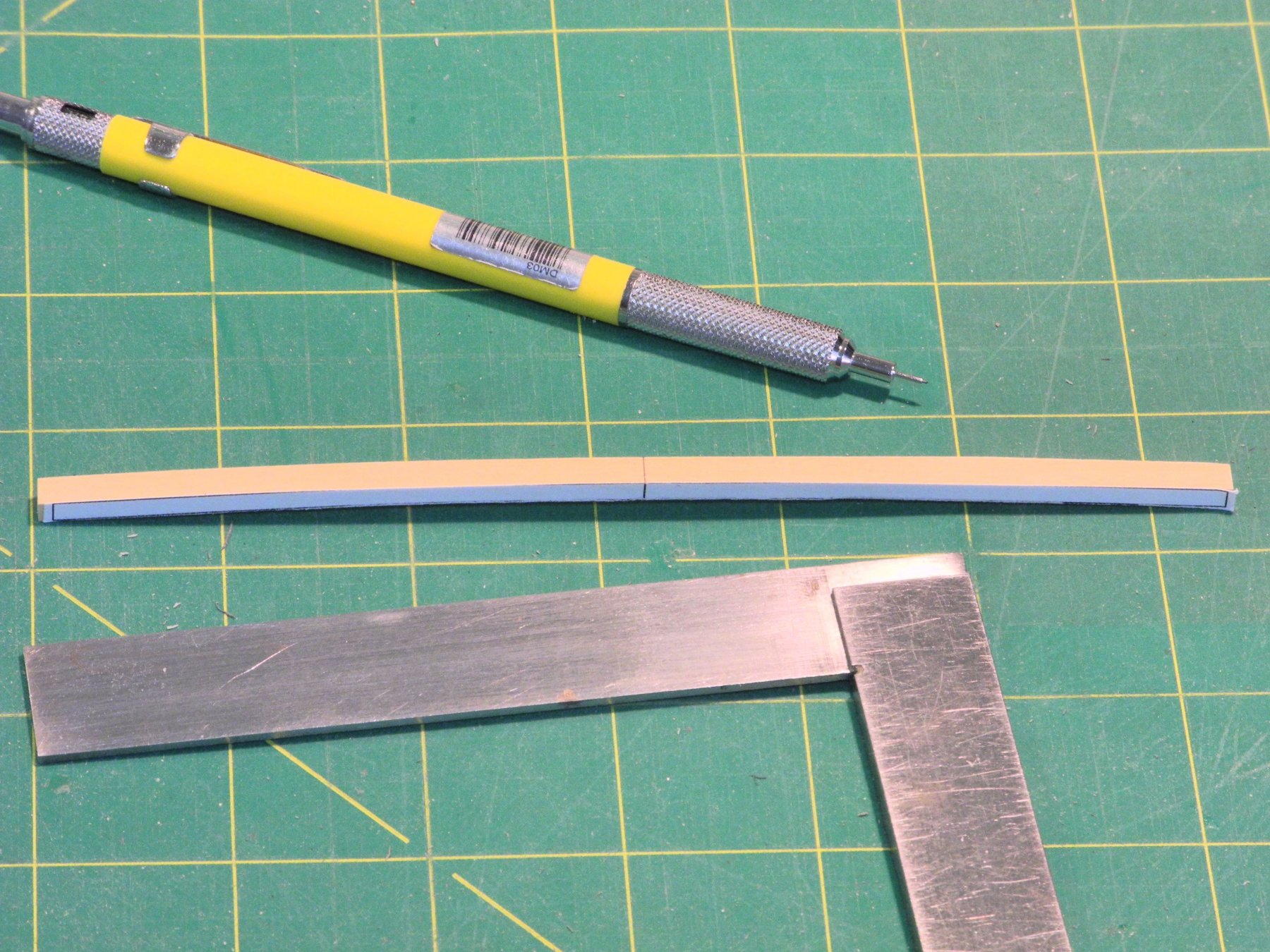
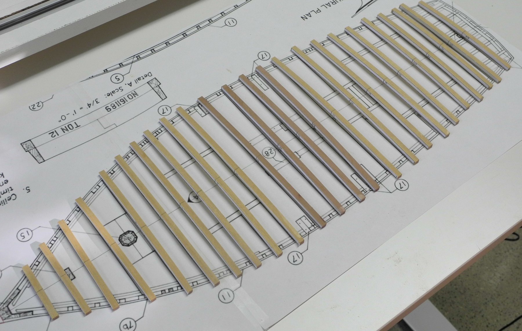
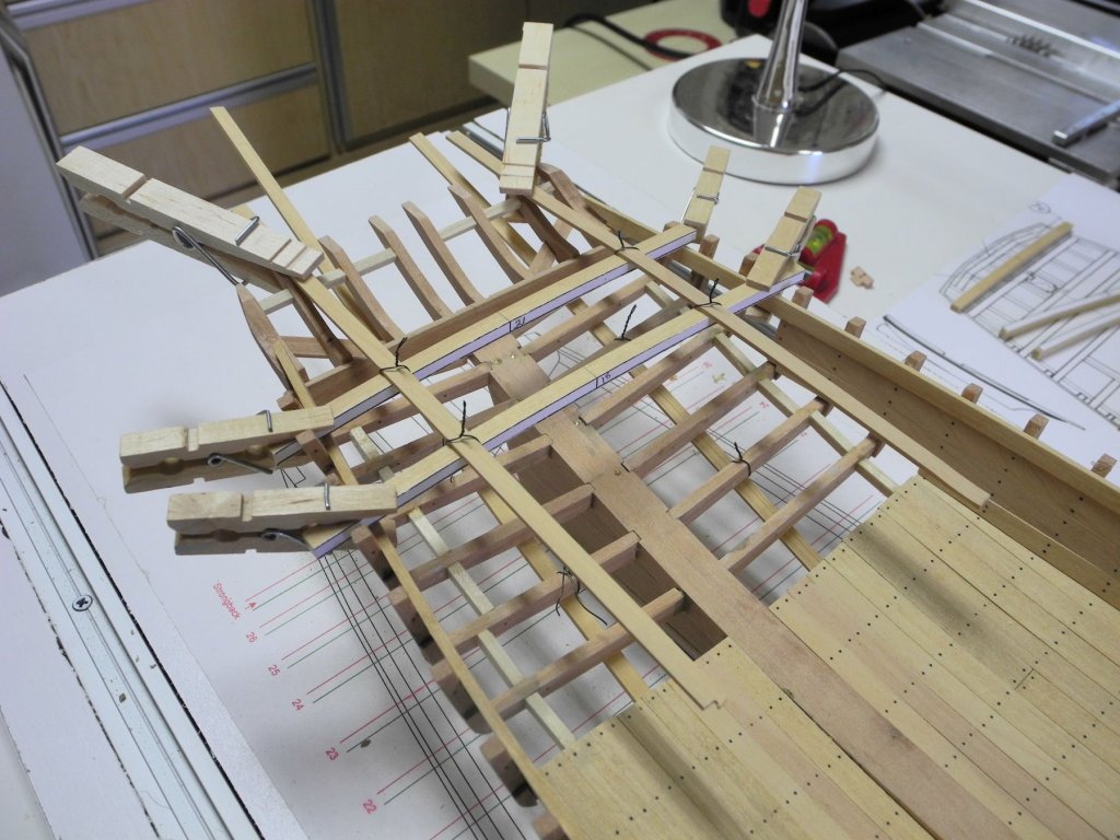
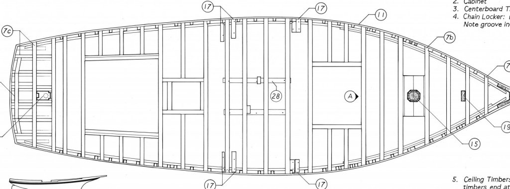
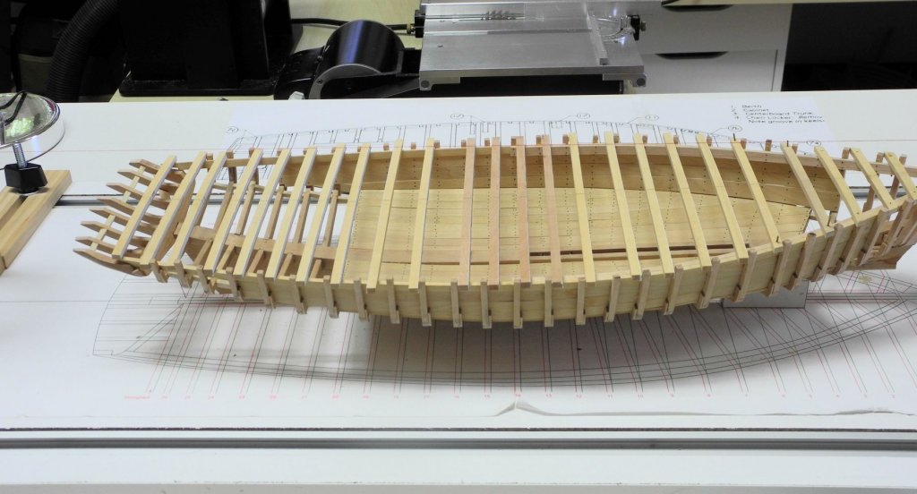
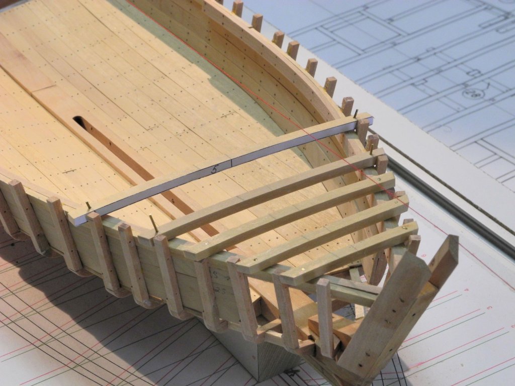
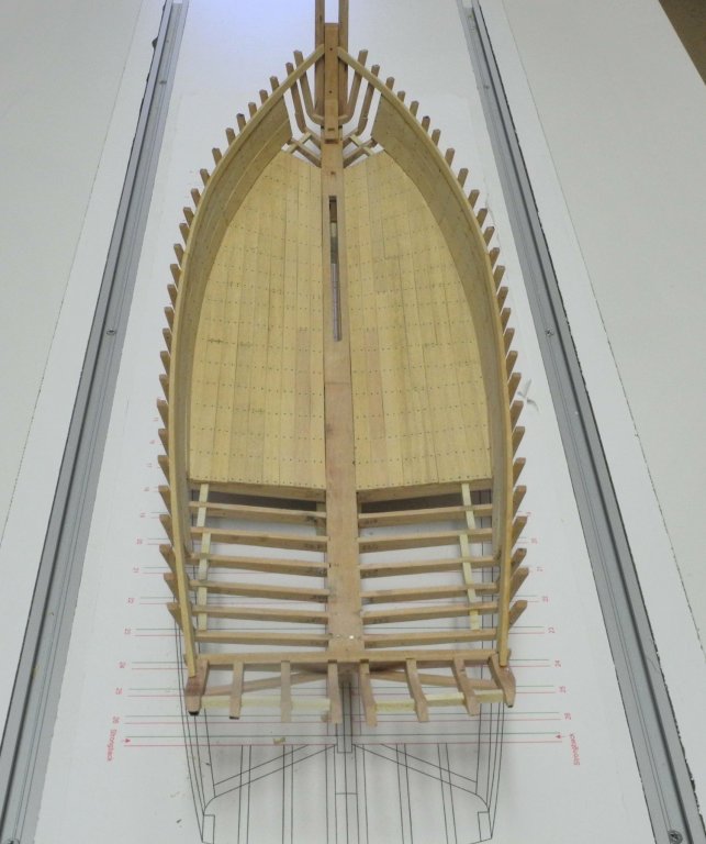
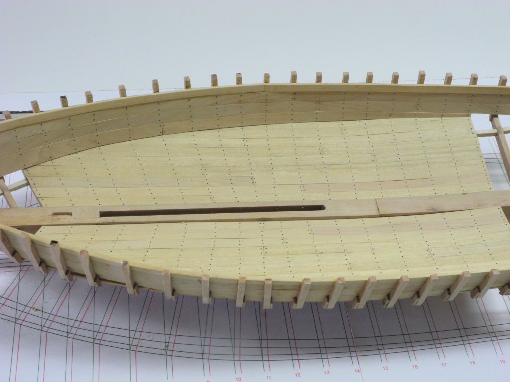
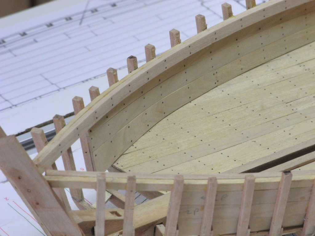
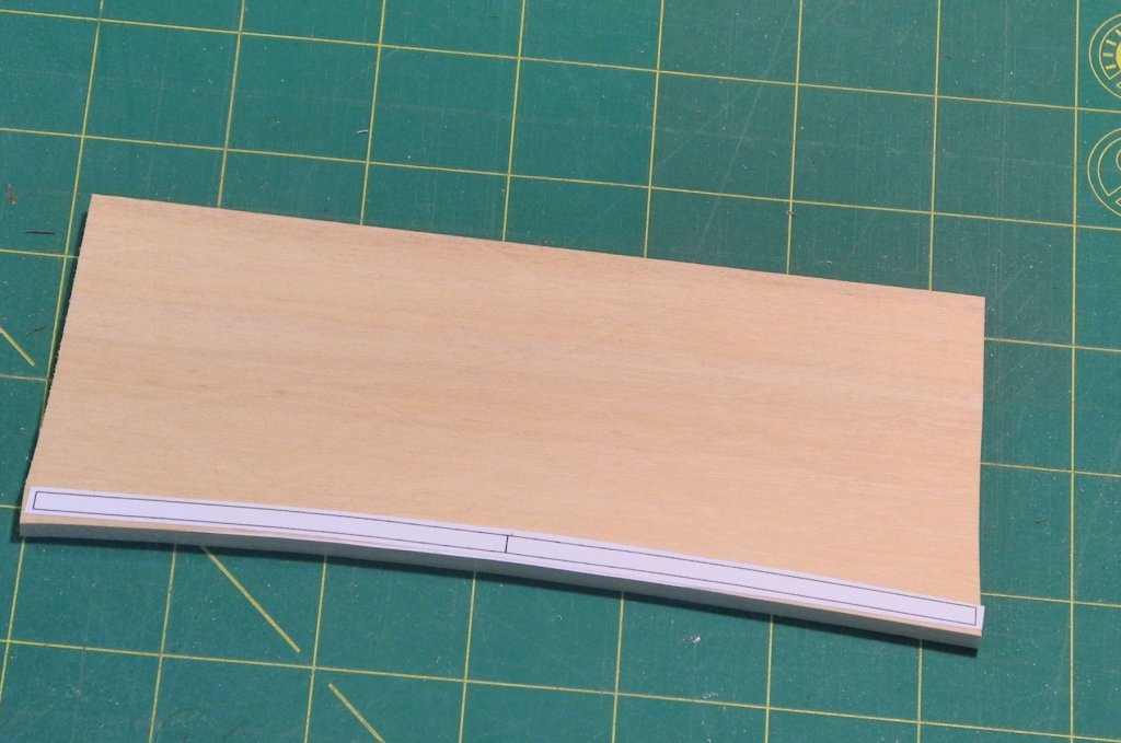
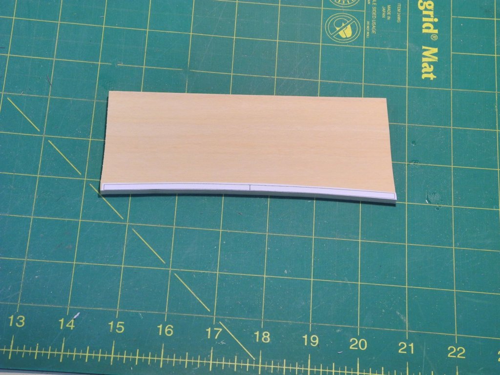
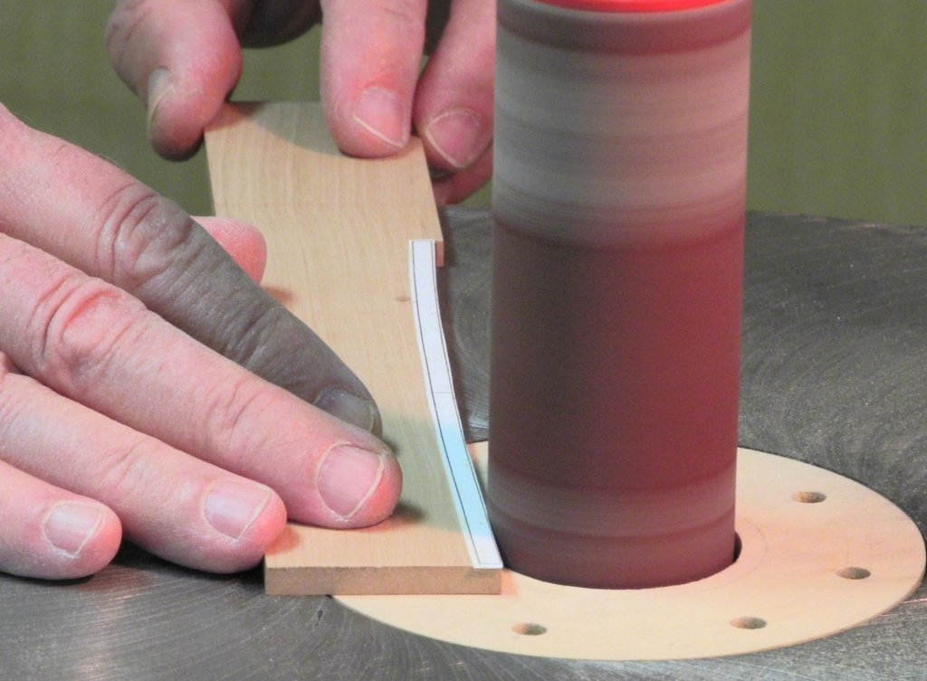
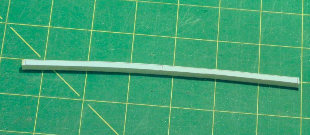
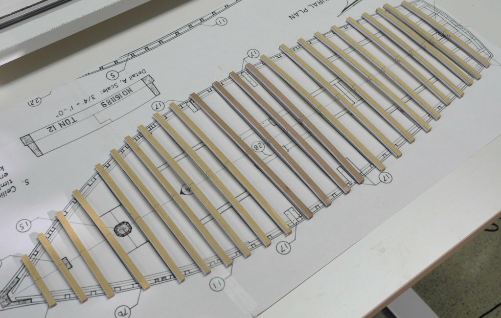
Part 16 – Deck Beams The ceiling in the hold is now completed. The bottom strake of the side planking required a lot of measuring and trial fitting, due to the sheer of the hold, as can be seen in the following photos. Kathryn’s deck clamps are made of pine (Castello on the model), but there is a reinforcing clamp added in Kathryn’s forward area. This reinforcing clamp is made of oak (Madrone on the model). Appropriate lengths of stock were soaked in boiling water and then clamped in position to dry. After these oak clamps had dried they were cut to final length, simulated bolts were added, and the clamps were then glued in place. There is a lot of interior construction to be done, and the location of much of the interior components is dependent on the location of deck beams, so the next effort is to shape the deck beams. Initially, every deck beam would be made to full length, regardless of whether it is a full length deck beam spanning the breadth of the hull, or it is a half beam located outside of a hatch. This would allow the half beams to have the correct camber. There was no information in the HAER documentation about Kathryn’s deck camber. Research showed a general rule of thumb of ¼ inch for each 1 foot of beam. This results in a camber of 4.2 inches, which was used for the deck beams. The HAER drawing that shows the configuration of the deck beams was printed to scale as an aid in locating the deck beams. Each beam would be made individually, so the basic drawing of the profile of the deck beam was duplicated an appropriate number of times. The following photo shows the HAER drawing (upper right) and the beams drawing (lower right). The beams drawing was initially printed to paper stock, but I found that when glue was applied the process of laying the drawing on a piece of wood could occasionally deform the drawing and result in a bad beam. So I printed these drawings on light card stock and this proved very satisfactory. The manufacture of the beams was fairly simple. After cutting out a single beam from the drawing drawing, school glue was applied to the back of the drawing. You’ll notice that the glue has a purple hue. I recently bought a set of glue sticks, and bought this type by accident. What I discovered is that the color actually helps to see that the glue is applied over the entire surface. When the glue dries it is completely transparent. (I later discovered that when the glue is washed off, the moisture causes the glue color to re-appear – this is a real help in making sure all of the glue is removed in the cleaning). The drawing was then glued to a billet of the appropriate thickness. The bottom of the beam was cut on the scroll saw almost to the line. And the spindle sander was used to bring the cut to the line. By forming the bottom edge of the beam before working on the top edge, there was plenty of stock to hold during this shaping. The top edge of the beam was then cut on the scroll saw. The top edge was then sanded to the line on the disk sander. Using the centerline of the drawing as a reference, the centerline was drawn on the top edge of the beam using a small square. This was a fairly straight-forward process, and I was able to manufacture the required 24 beams in an afternoon. You'll notice that there are 4 beams in Kathryn's center that are darker in color. All of the deck beams are pine (Castello on the model) except the four beams that are located under the dredging winder. Those beams are oak (Madrone on the model) - so there's a difference in color. I’ll probably make a few more beams as backups. These beams won’t be installed until the appropriate time – when an interior component depending on the placement of a beam is being installed. Thanks everyone!


- 878 replies
-
- 21
-