Mahuna
-
Posts
1,504 -
Joined
-
Last visited
Content Type
Profiles
Forums
Gallery
Events
Everything posted by Mahuna
-
 Thanks Rich, but my shipway is copied from some other modelers' approaches, so I think that wouldn't work. Thanks Patrick. It's a good feeling getting to this point. Now I have to work on some of the more difficult parts. Thanks Druxey. It's amazing to think that Kathryn survived over 100 years before the recent major reconstruction. So many younger skipjacks have already rotted away. Glad to hear from you Carl. I'm not sure what matches you're referring to - I'll have to look for it.
 -
I've never seen parceled shrouds on a model before - your work is amazing. The level of detail at this scale is really impressive. I do like the railings painted white. I was wondering how unfinished brass would age on a model.
- 3,618 replies
-
- 8
-

-
- young america
- clipper
- (and 1 more)
-
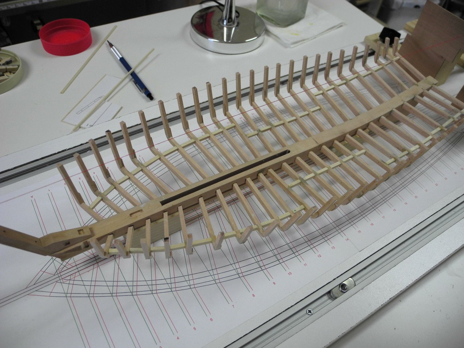
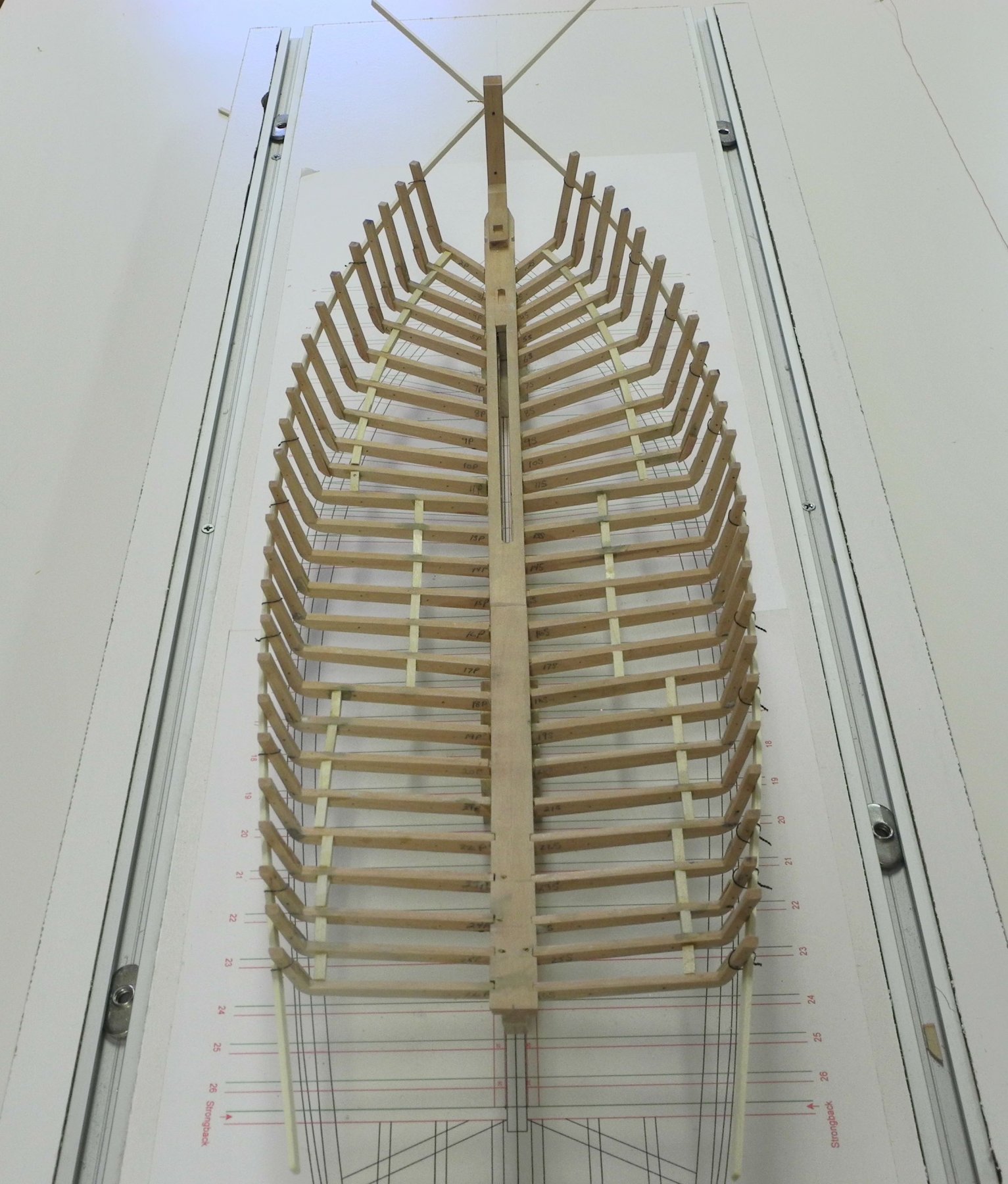
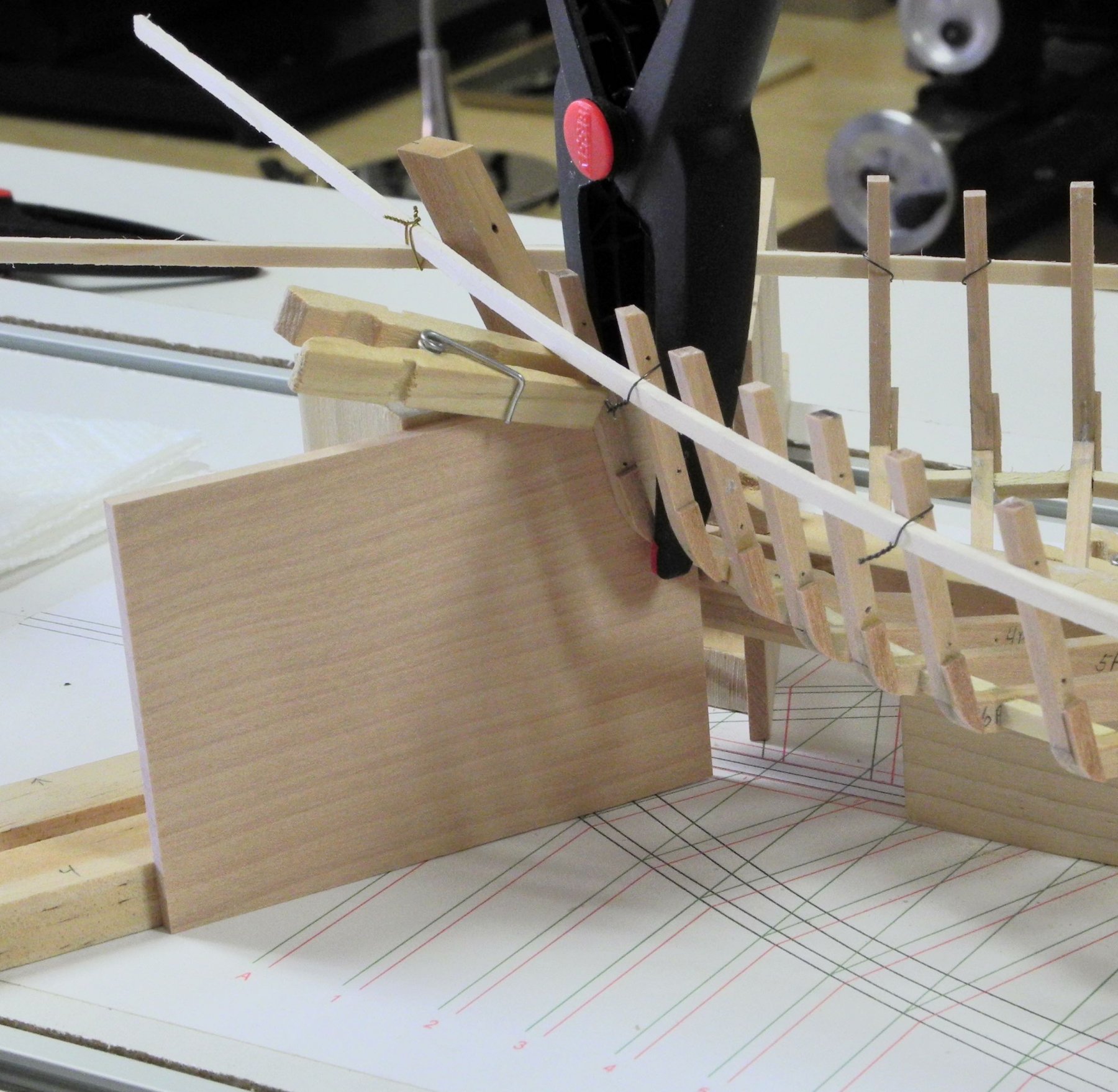
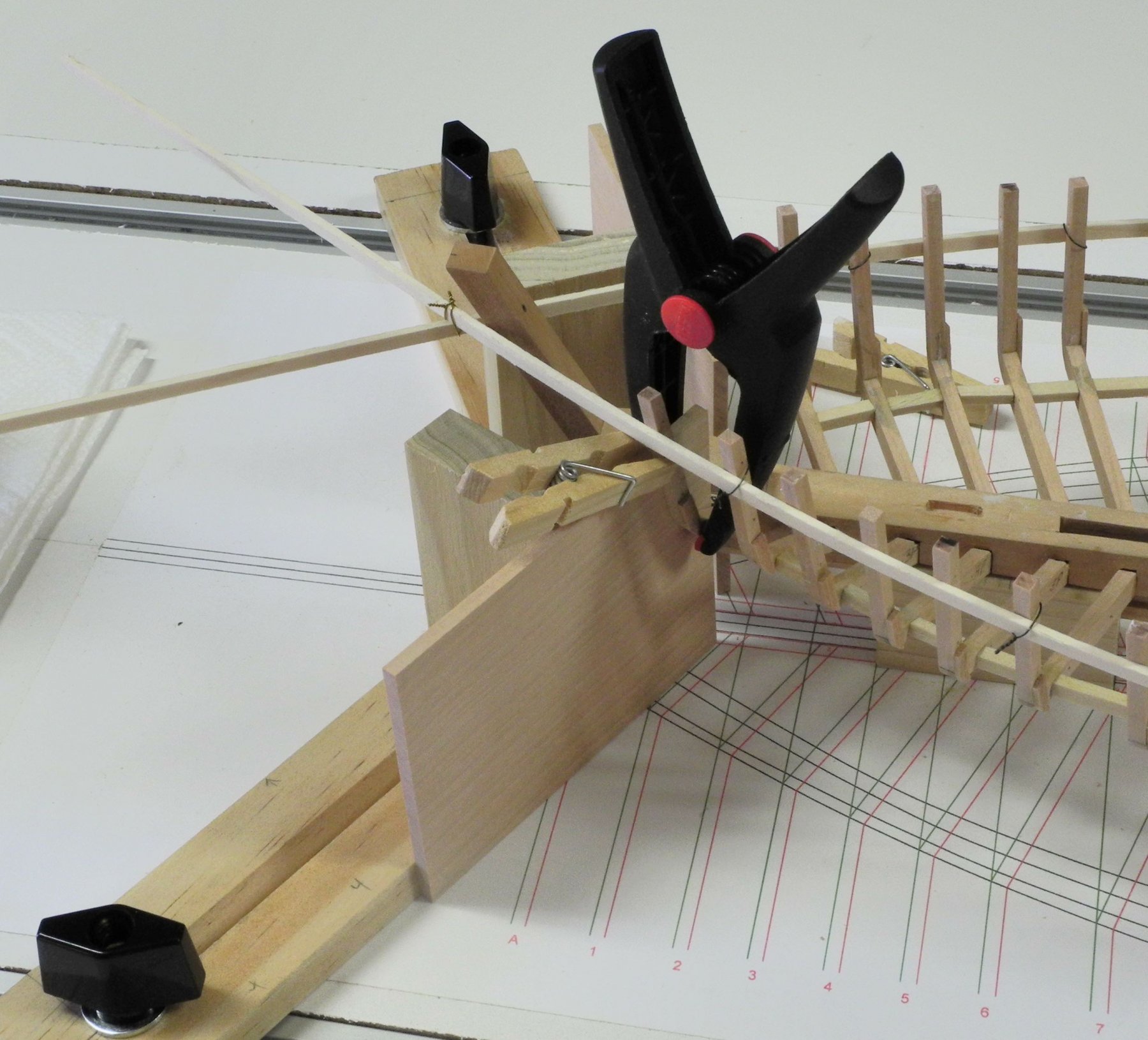
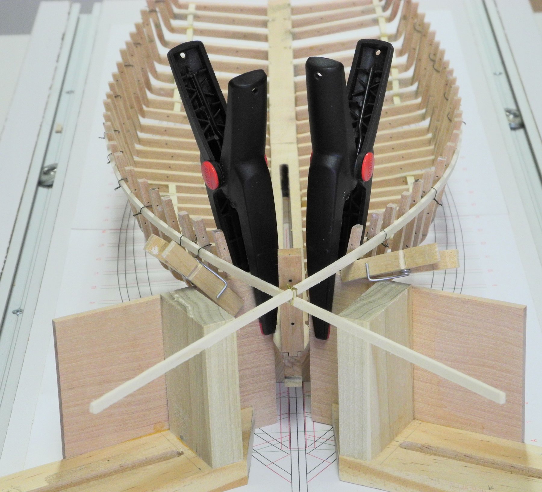
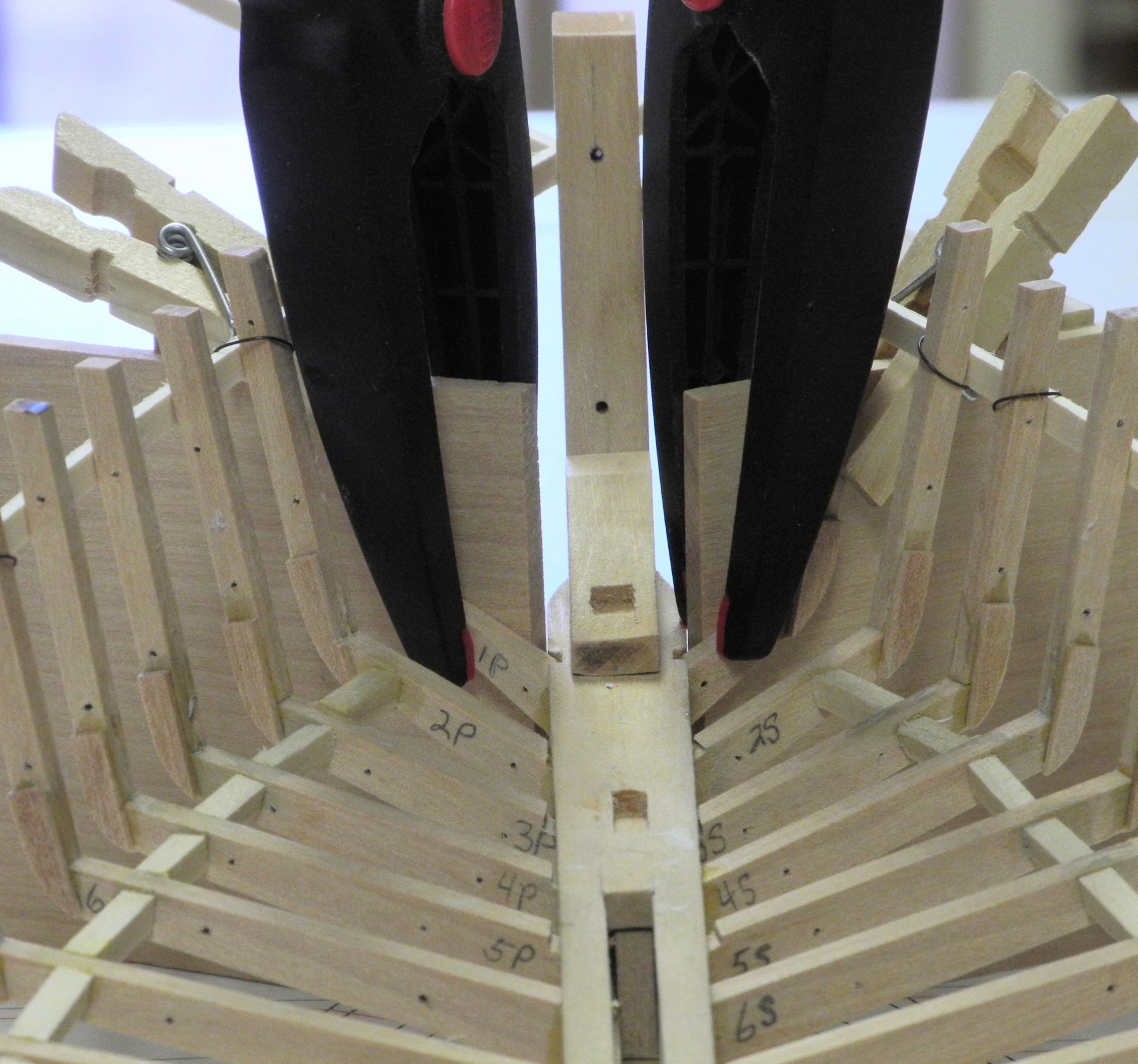
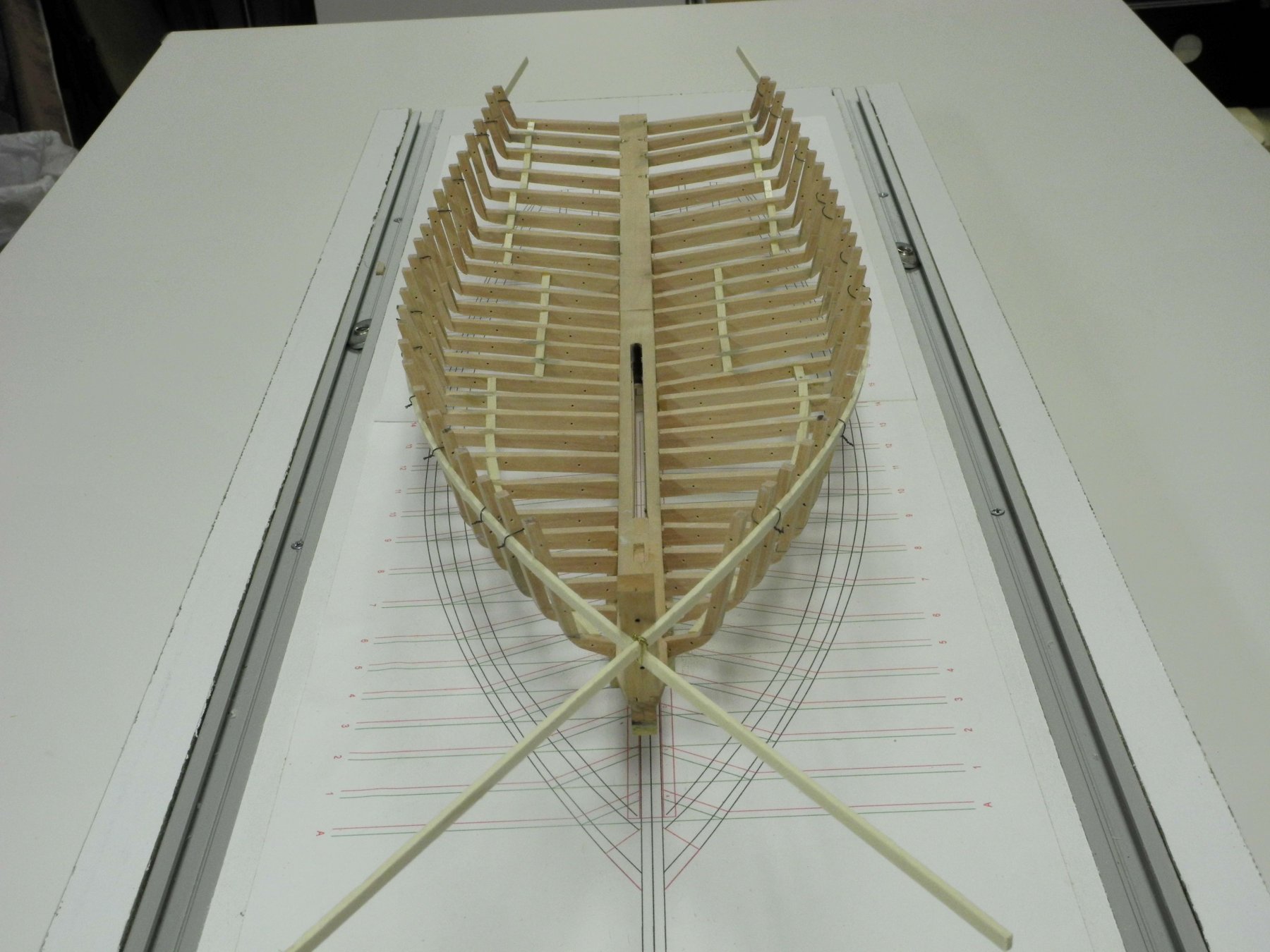
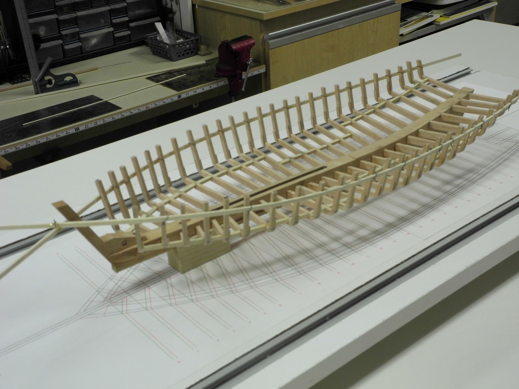
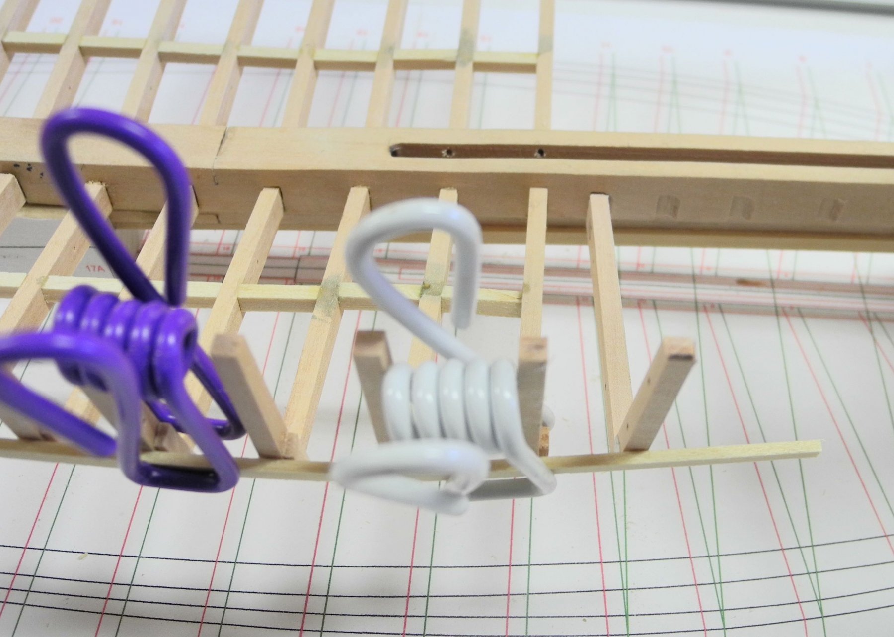
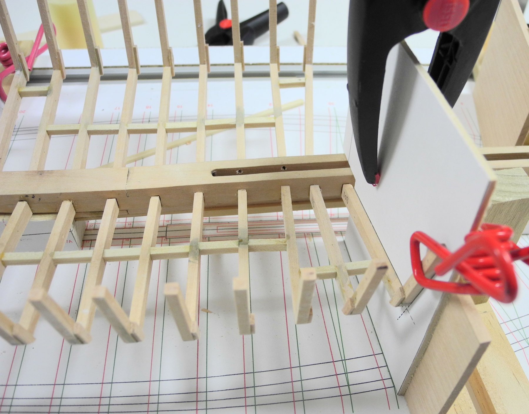
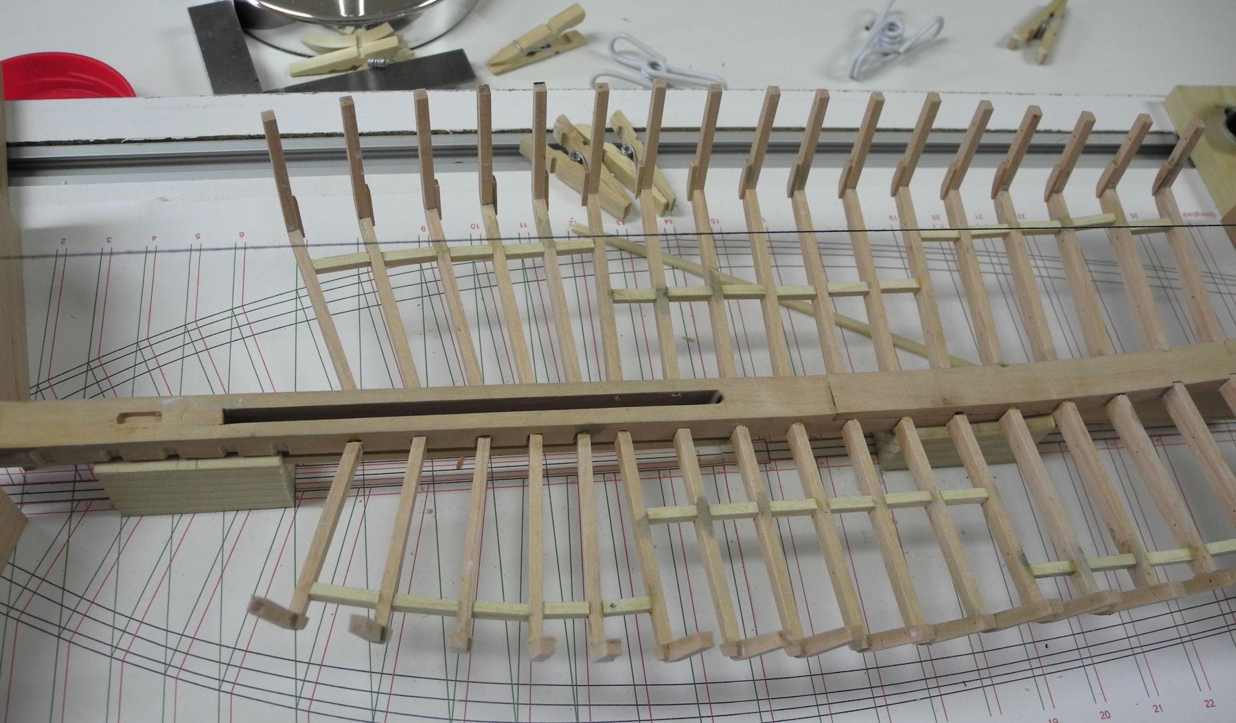
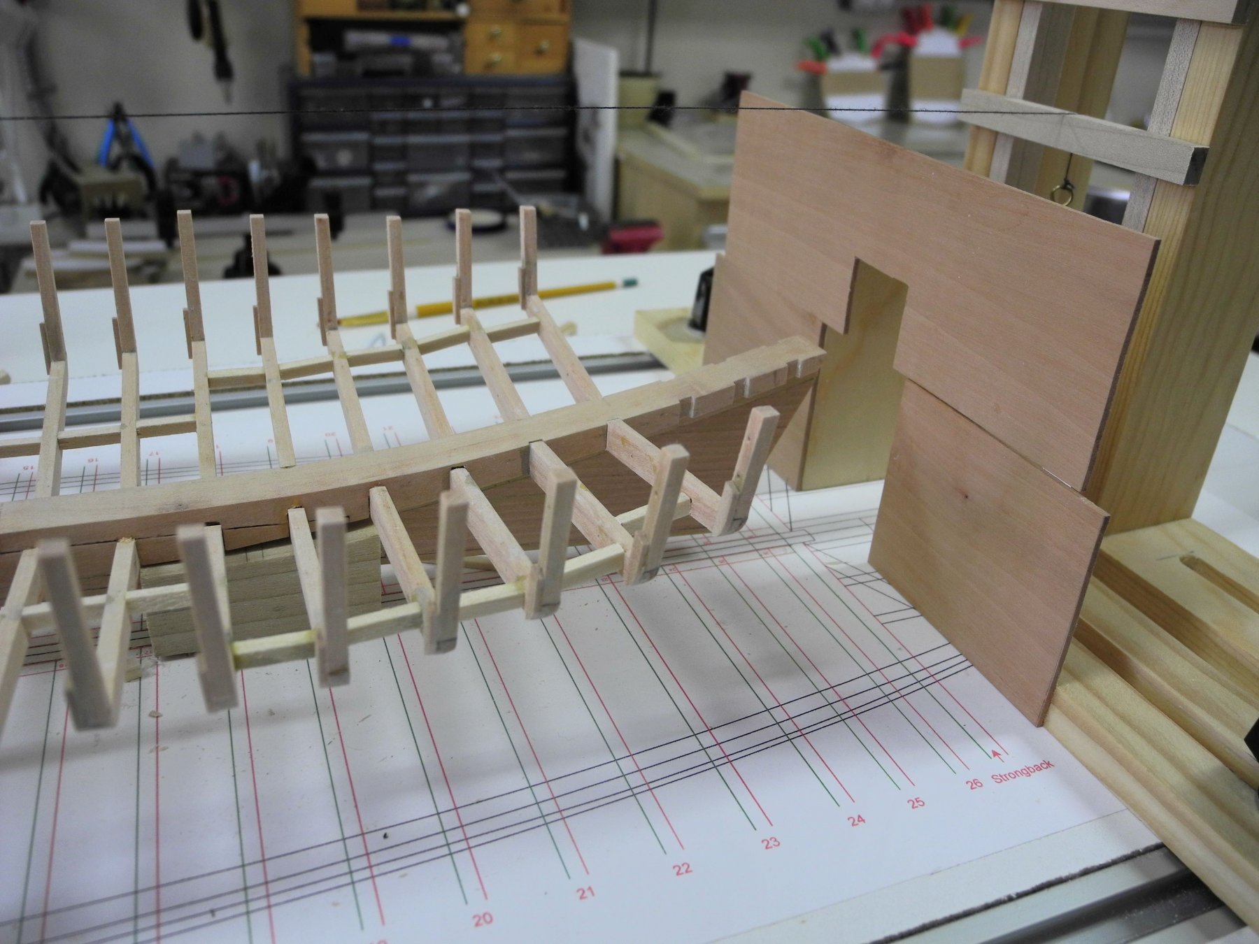
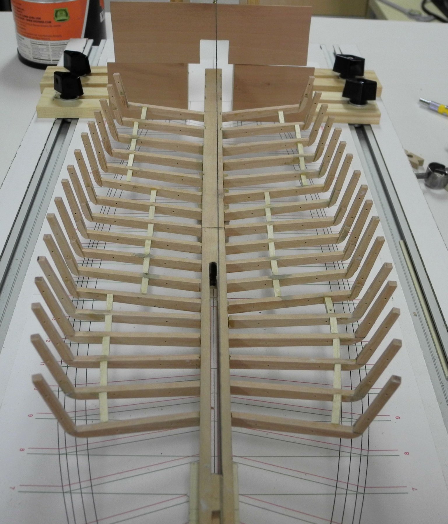
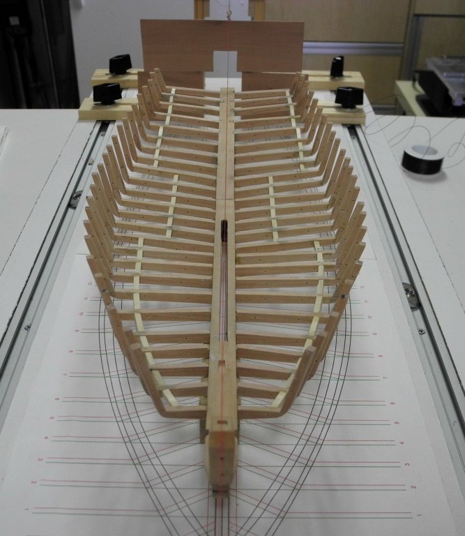
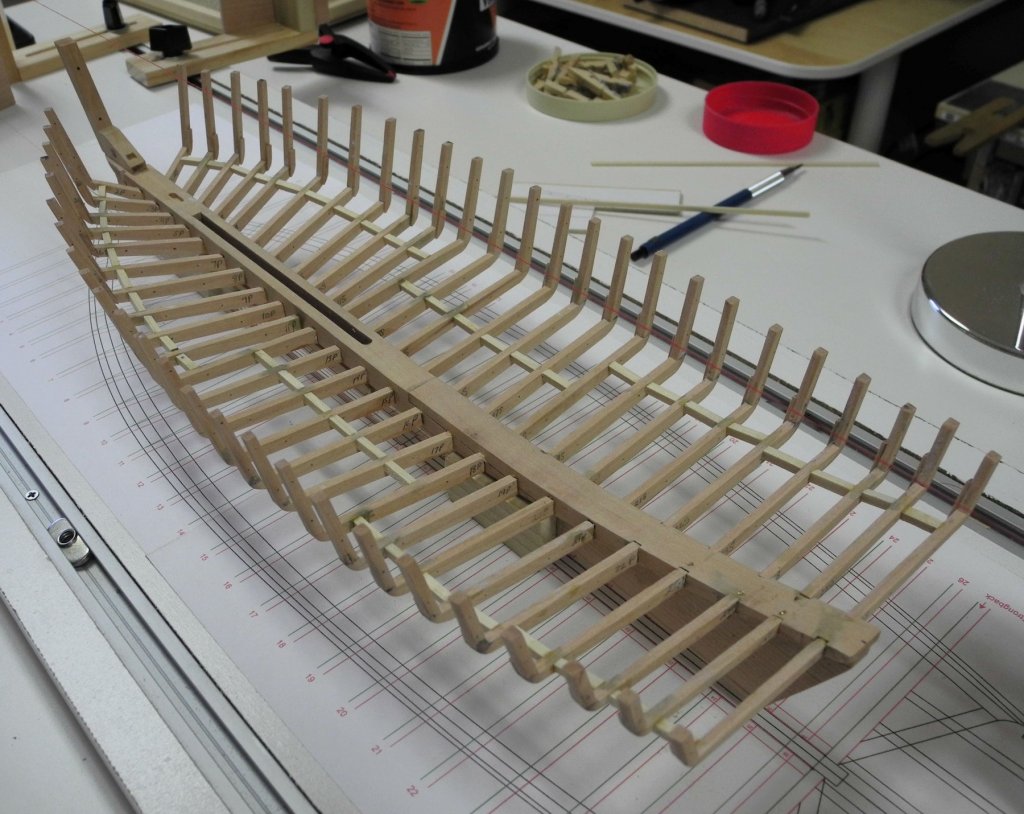
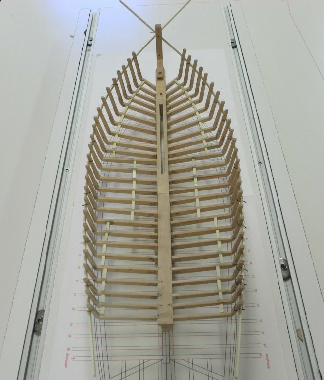
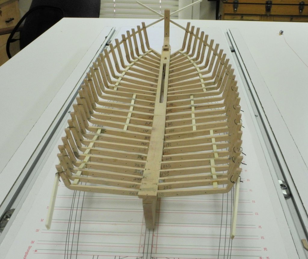
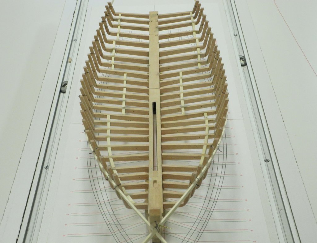
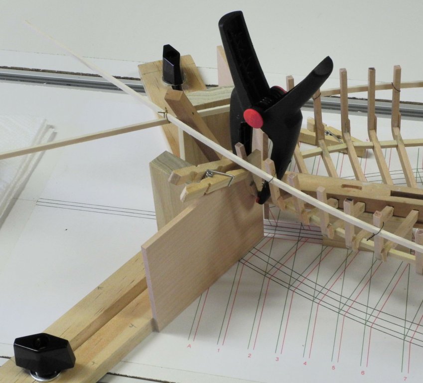
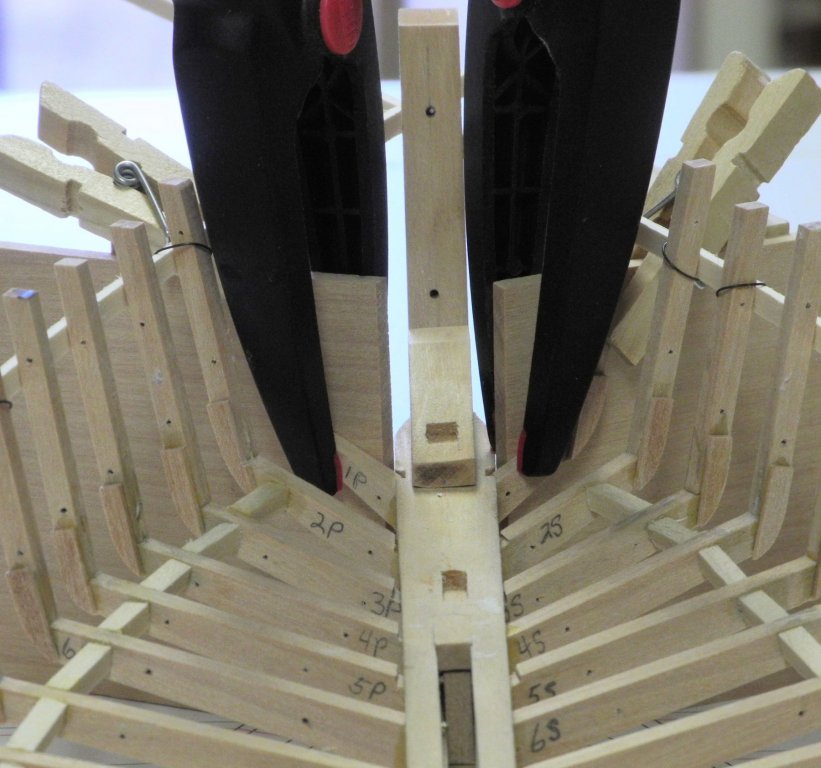
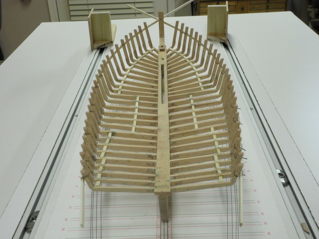
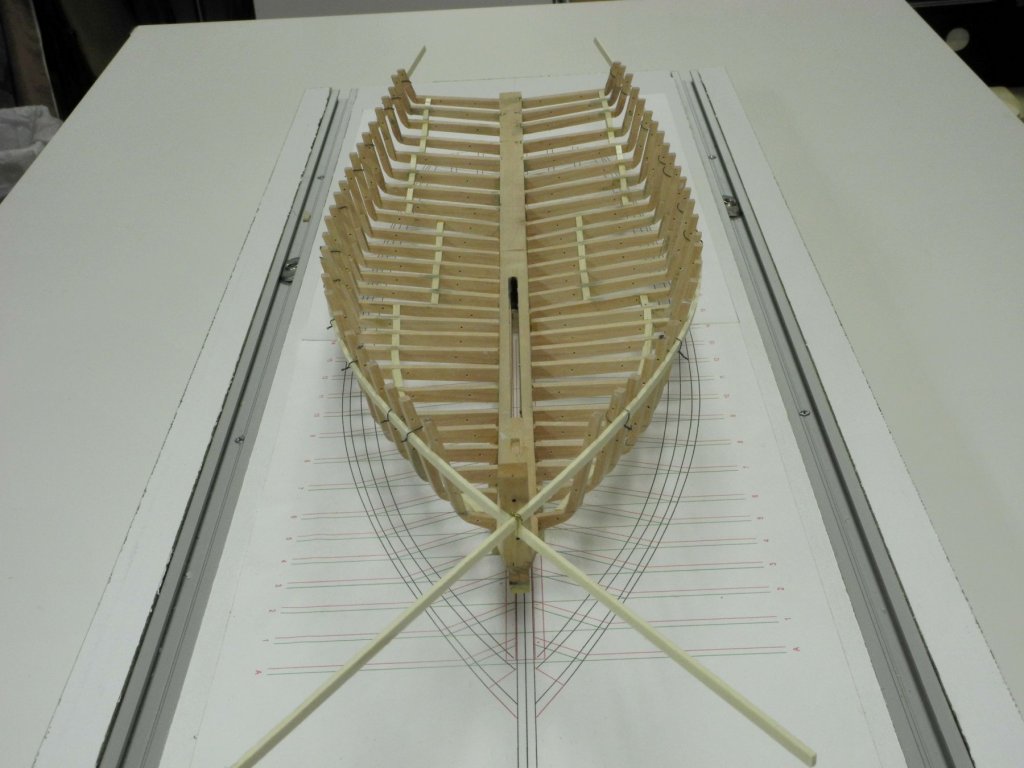
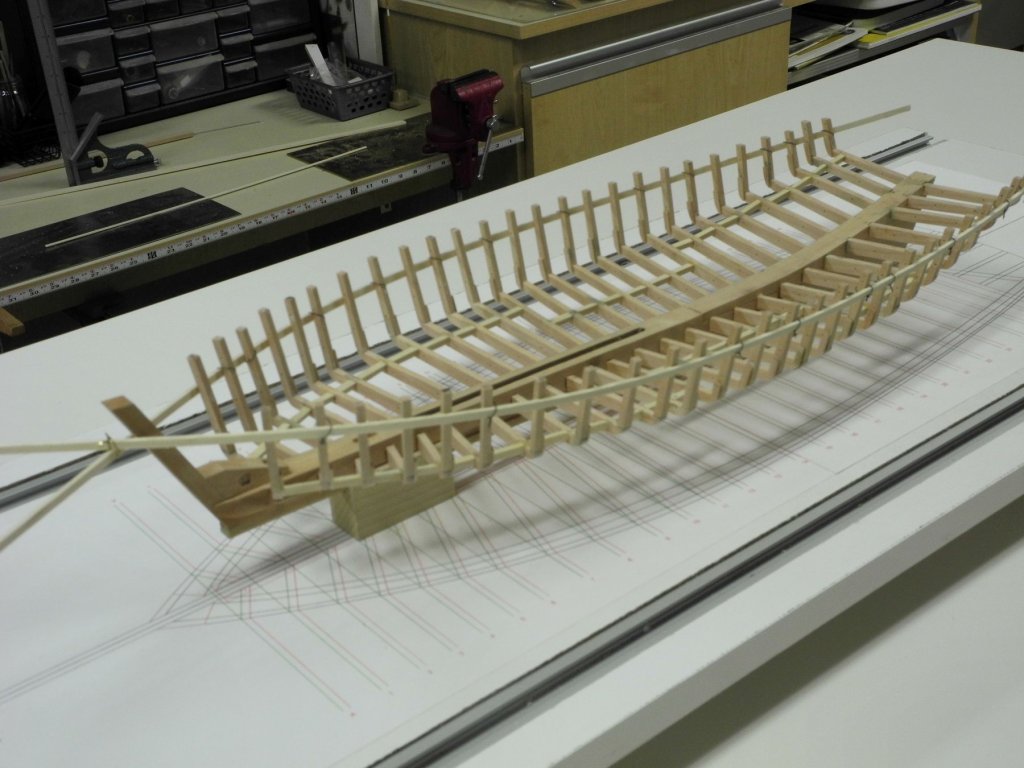
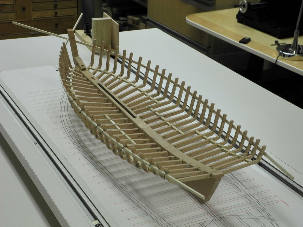
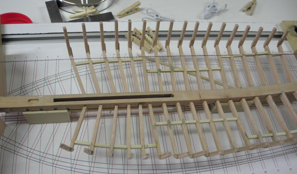
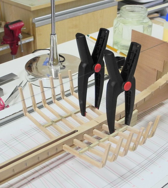
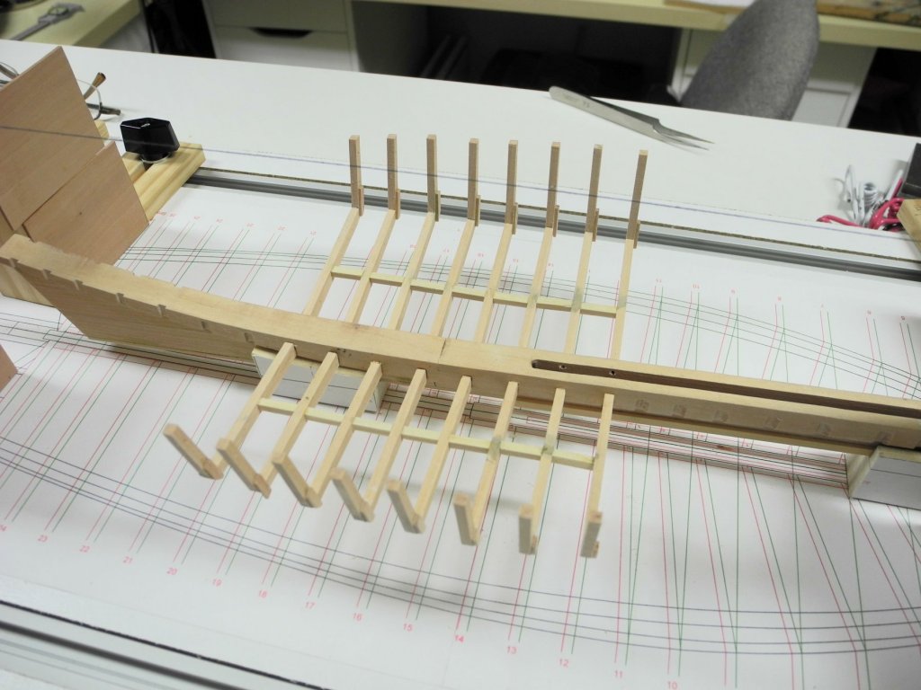
Part 10 – Frames, cont’d The installation of frames 2 through 26 followed the process outlined in the previous posts. The following photos show Kathryn with those frames installed. Close inspection shows that some of the frames are out of alignment by as much as 1/16”, likely as a result of some slight errors in their construction or in the installation. In most models this can be adjusted by fairing the frames prior to planking. However, Kathryn’s frames are delicate, and I’m not comfortable with the idea of fairing them through sanding. In checking the frames by holding a ribband against them, I observed that the frames are fairly flexible and move in the required direction fairly easily. Since the first planking and/or timbers to be installed will be in Kathryn’s interior, I decided to temporarily install ribbands on the outside of the hull. I used 1/16” x 1/8” poplar ribbands, and attached them to the hull by wiring them to some of the frames using 34 gauge wire. The following photos show Kathryn with the ribbands installed. These ribbands were installed prior to the installion of frame 1, so that frame 1 could be properly aligned with the flow of the ribbands. The installation of frame 1 did not depend on the drawing of the frame, as in the other frame installations. Instead, the installation jig was lined up with the construction plan drawing and adjusted for the placement of the mortise. The frame was then installed against this jig and using the ribband for positioning, as in the following photos. The clothes pins used as clamps in the above photos are miniature clothes pins - this illustrates the small size of the frames. The installation of frames 1 through 26 is now completed. There is one last frame (frame 'A') that will be mortised into the stem knee, but this will be completed after the installation of the knightheads to ensure a smooth flow of planking at the bow. The following photos show the model with frames 1-26 completed. The next task will be the installation of the stern timbers that support the transom. This will be my first attempt at this type of installation, and I still have quite a few questions about how to proceed. In the next post (and probably several after that) I will try to explain the open questions that I have, in the hopes that I can get some answers/direction from the more experienced modelers who are following Kathryn’s progress. I hope to be able to start this dialogue by early next week. Thanks everyone!


- 878 replies
-
- 24
-
-
Couple questions of Sherline Mill purchase
Mahuna replied to sfotinos's topic in Modeling tools and Workshop Equipment
I have both the mill and the milling column for the lathe. The milling column works really well, but the x-axis is limited to the travel of the lathe's cross-slide. It would be a good way to start milling, and I've found having both to be a great advantage when I have repetitive milling activities that would require frequent changing of tooling. -
Thanks Ron. Delicate is the key word - Kathryn is pretty fragile at this point, and will be until I can get some planking on.
-
Thanks Patrick. Yes, Kathryn is starting to shape up and pretty soon I'll need to deal with the bow and stern timbers - these have me a little confused and I'll need to study it some more. Great fun!
-
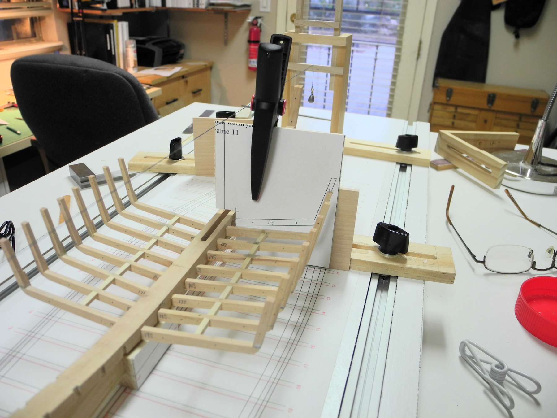
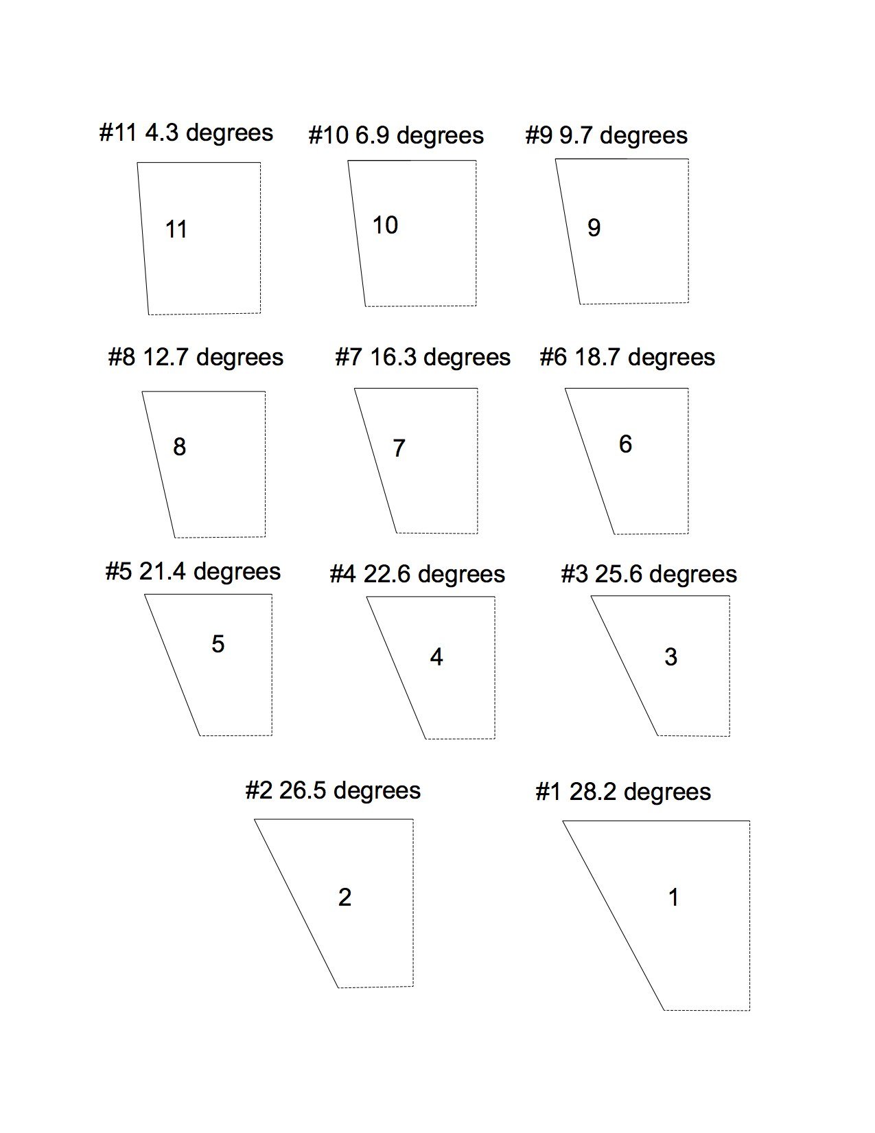
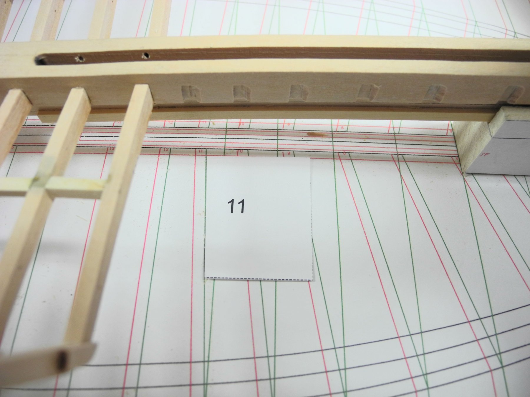
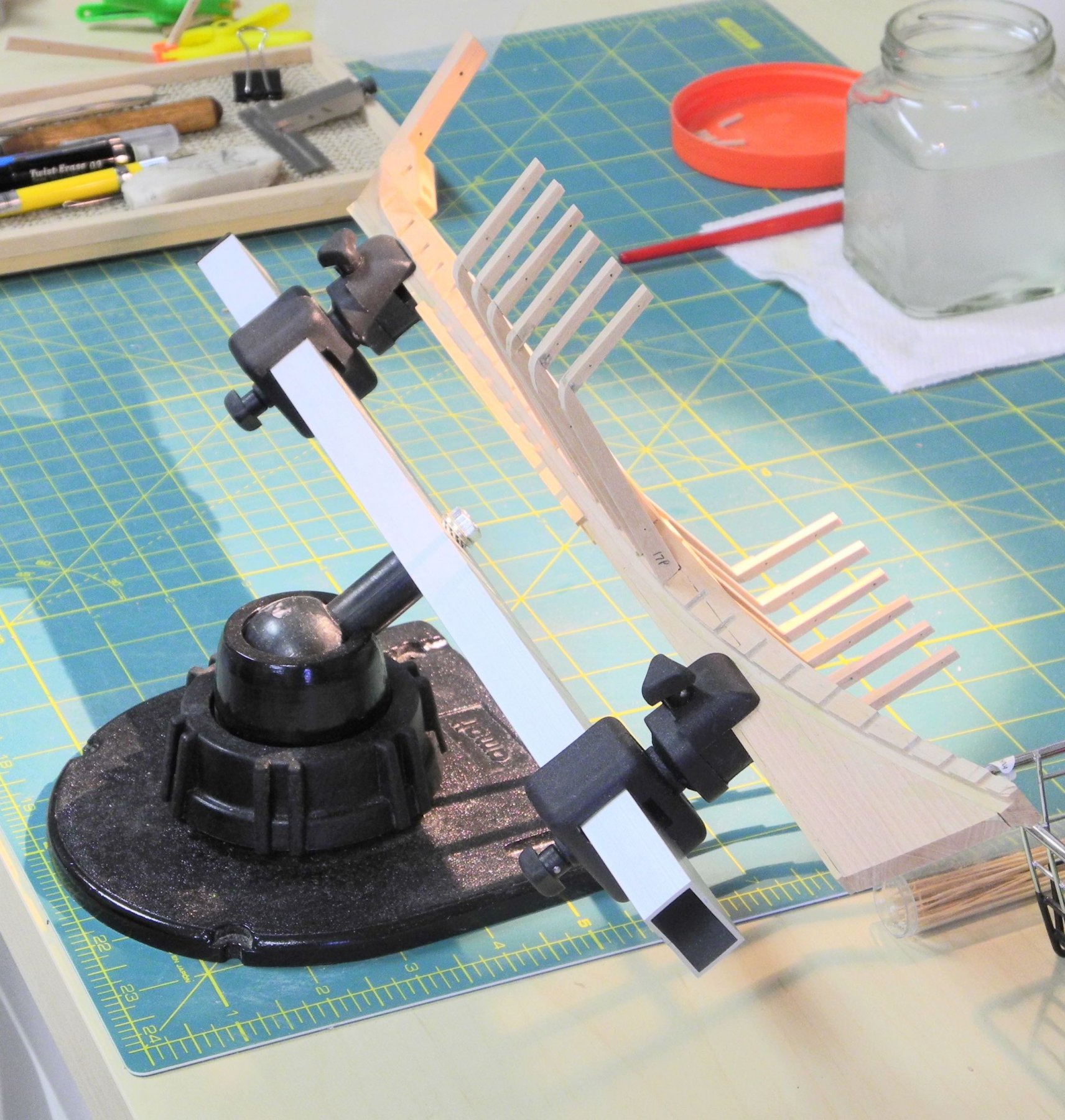
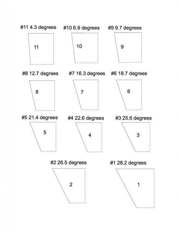
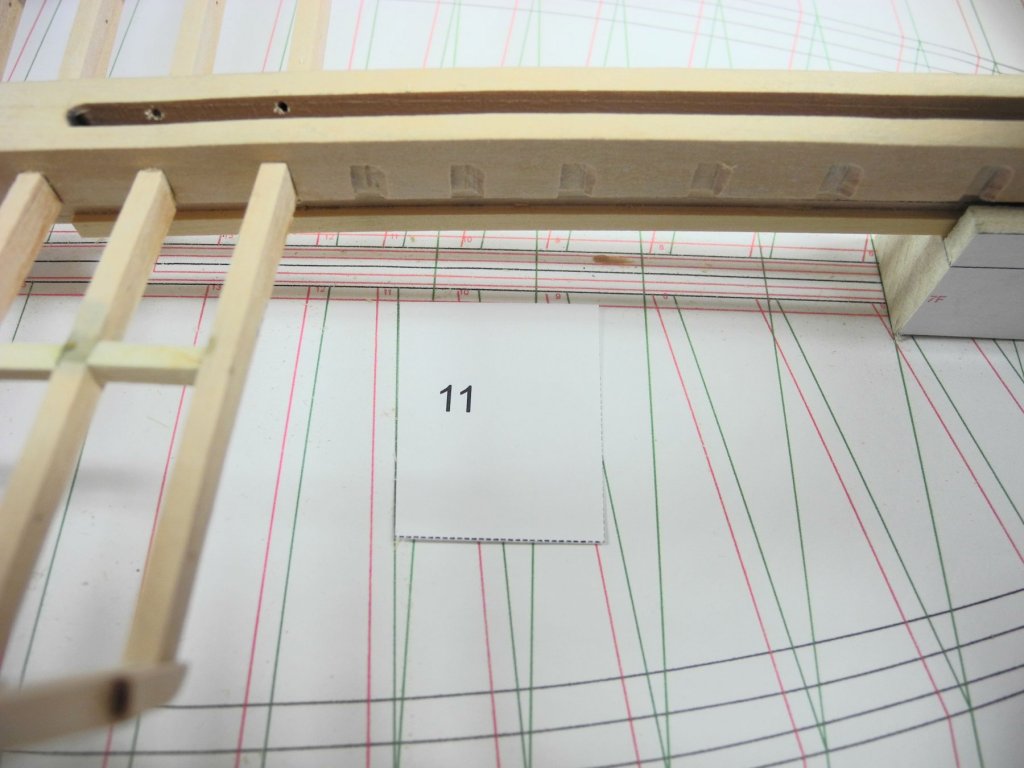
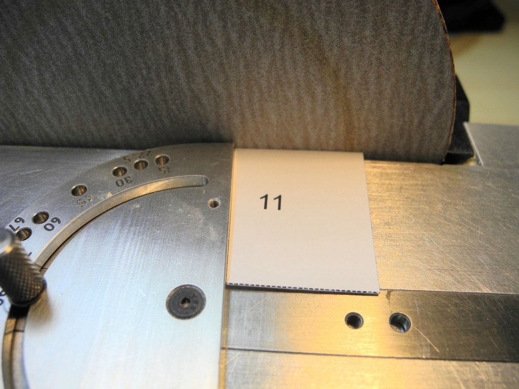
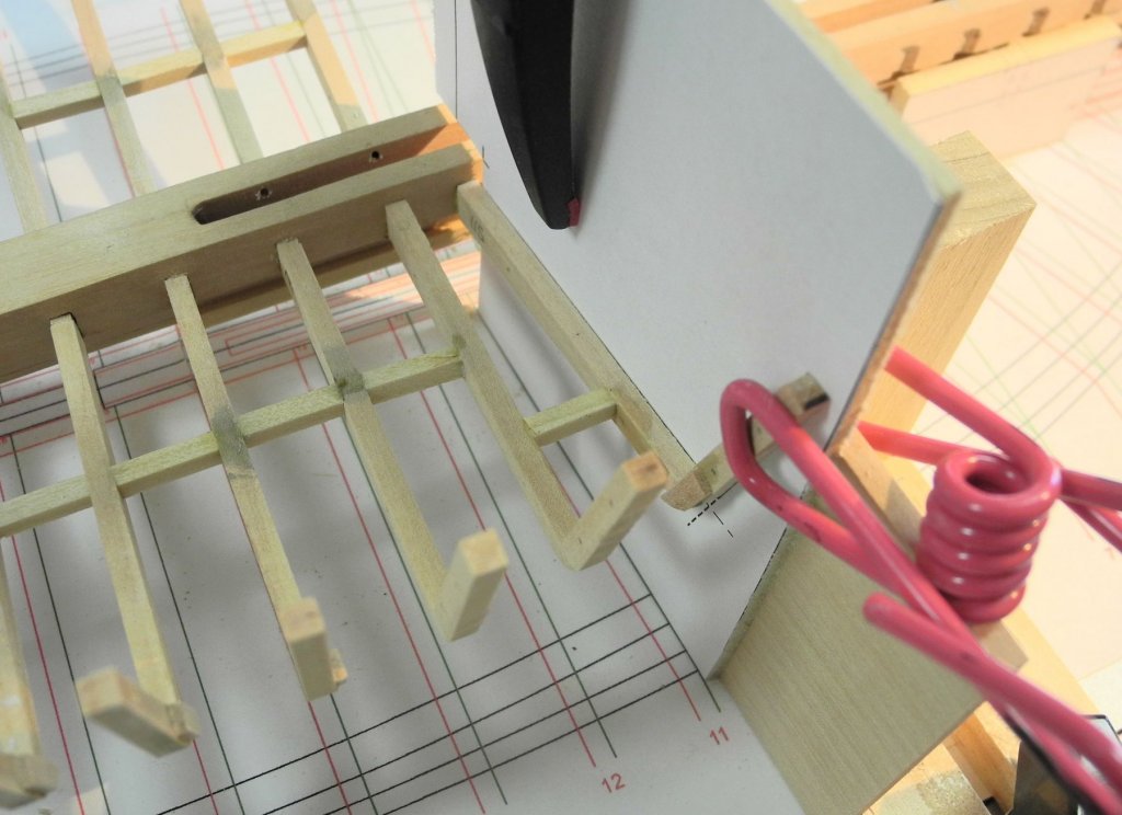
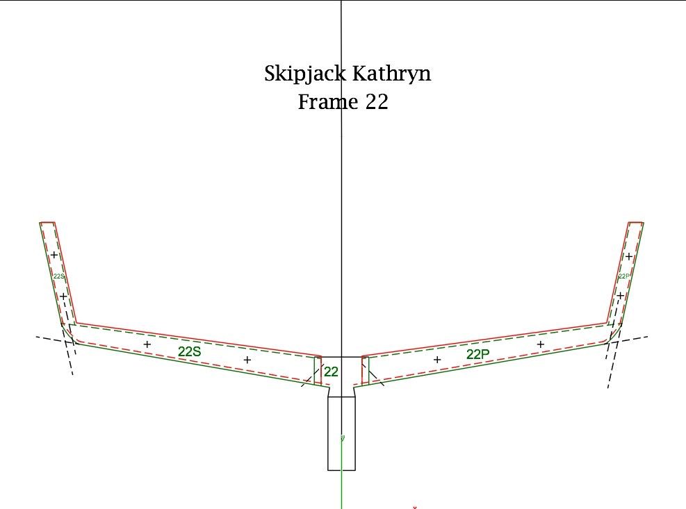
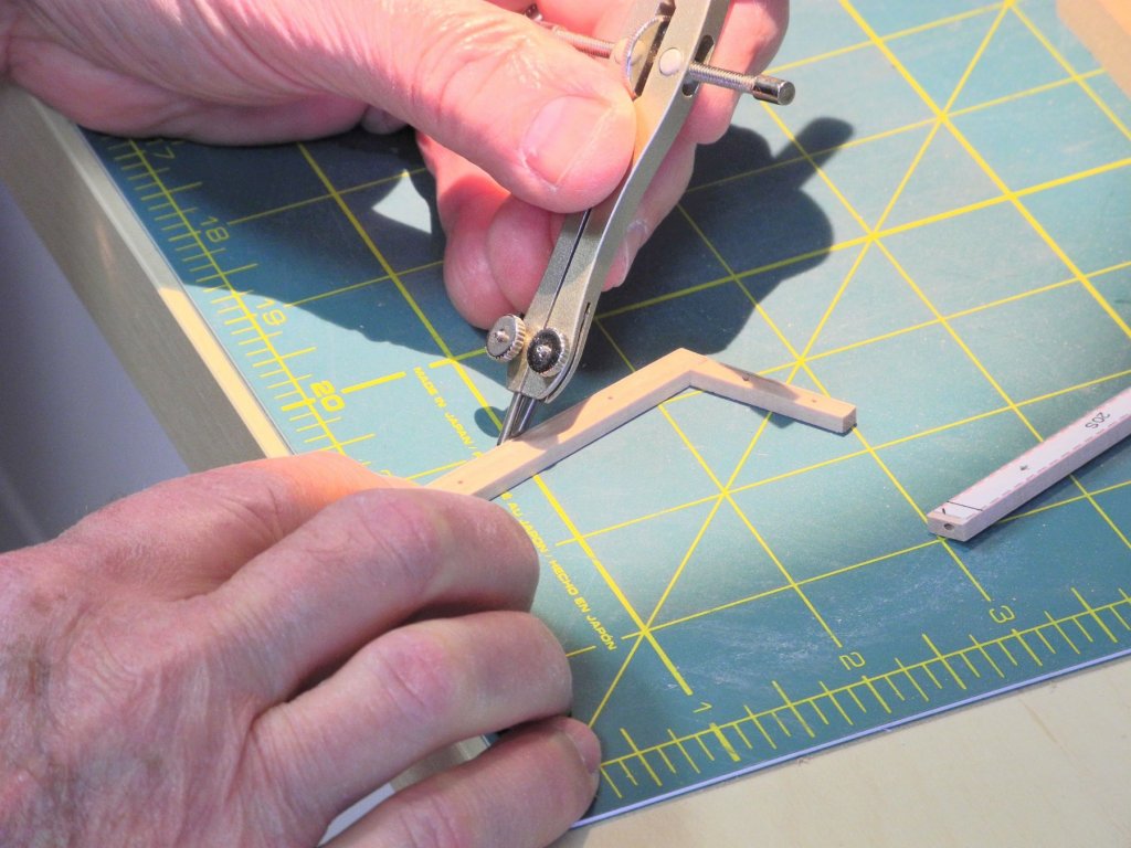
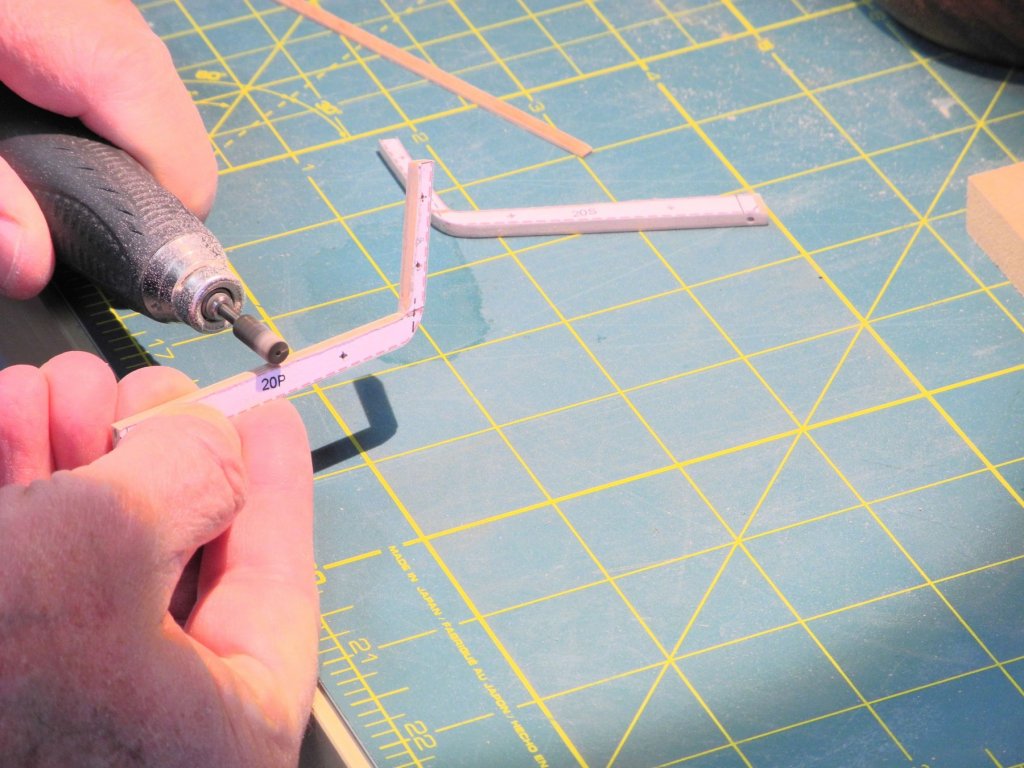
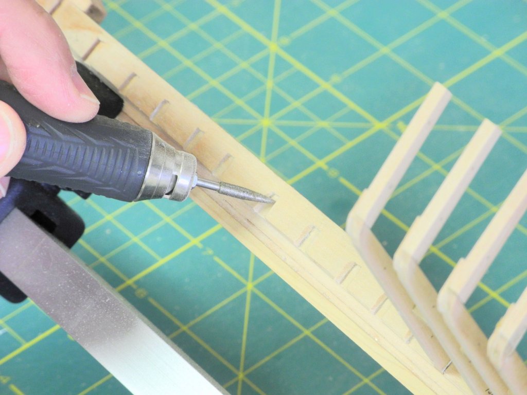
Part 9 – Frames, cont’d There is no mention of cant frames in the HAER documentation, but in the drawings the forward most 11 frames on Kathryn appear to be canted. I’ve decided to construct those 11 frames as cant frames. The framing jig for the cant frames is essentially the same as for square frames, except that only one side of the drawing is used at a time, due to the angle the jig must be held at, as in the following photos. It is also necessary to angle the base of the frame floor timber so that it sits flush against the keelson. Each of the eleven frames will sit against the keelson at a different angle, so these angles were measured from the half-breadth plan and recorded. Templates were created so these angles could be accurately created on the frames, as shown in the following photo. The following photo shows a template being checked against the drawing on the shipway. The templates were printed on card stock and are used to adjust the miter gauge on the disk sander to the appropriate angle. A temporary batten – held by clamps – is used to double-check the fairness of the frames. The cant frames were installed in the same way as the square half-frames. A stiffening brace was added between frames while the new cant frame was still in the installation jig. The aftmost square frames – 22 through 26 – need to be faired to conform to the rising shape of the keelson in that area. The drawings for these frames indicate the fairing needed. In this drawing the color and configuration of the lines indicates the shaping required: · The red lines indicate the aftmost face of the frame, while the green lines indicate the forward face. · The frame is cut out along the solid lines, whether red or green, and then the dashed lines indicate the edge of the frame that that needs to be reduced (the cutting line). Since the drawing is pasted to the front face of the frame, the first task is to draw a line corresponding to the red dashed line on the aft face of the frame. A compass is used to measure the distance of the dashed line from the edge of the frame, and this compass setting is used to draw a corresponding line on the aft edge of the frame. The frame is then shaped using a stump cutter in a rotary tool. First, the cutter is used to cut the aft edge of the frame down to the drawn line. It is then used to flatten the entire outer edge of the frame at the appropriate angle. The forward face of the frame is shaped by cutting to the green dashed line. The braces used for the cant frames and for the aftmost square frames need to be angled to fit securely against the frames they support, as shown in the following photo. Cant frames 7 through 11 have been installed at this point. The square frames have been installed to frame 23. So this leaves 6 cant frames and the aftmost 3 square frames to be installed. I hope to have these frames completed sometime next week. There are a couple of frames in the midship area that concern me, and I may need to remove and re-install them. But I won’t think about that until all of the frames have been installed. Thanks everyone for following, for the ‘LIKES’, and for the encouraging comments.


- 878 replies
-
- 24
-
-
Thanks, Bob. That makes sense. Given her size I don't think Kathryn would have been built upside down as in other skipjacks - that, and the herringbone bottom planks of the typical skipjack provide some structure to the boat. Since Kathryn's longitudinal bottom planks would probably require that the framing is completed prior to the planking, I think your second alternative is probably the way she was built.
-
Hi Rich: Good work on the A/C! I'm looking forward to seeing your shop this weekend.
- 1,135 replies
-
- 2
-
-
- model shipways
- syren
- (and 2 more)
-
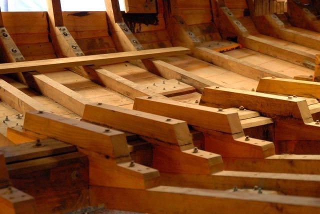
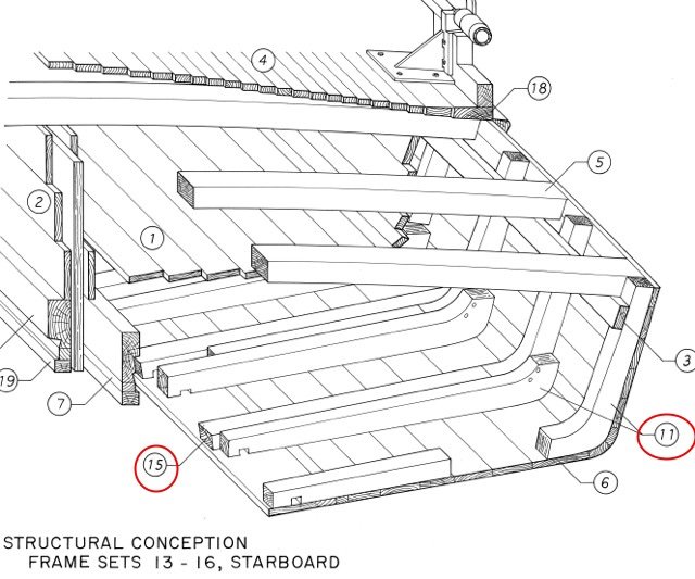
I thought I'd share a couple of photos of the framing in the actual Kathryn. The first is from the HAER drawings. The frame pointed to by the number 15 is one of the original frames. They don't look like the joint was held together by much more than a few bolts, and I would love to know how they built Kathryn. They must have used a lot of temporary ribbands to hold her together before she was planked. The mortising of the frames into the keelson also looks very flimsy. The following photo is from the recent rebuild that was completed in early fall 2015. As can be seen in the photo there is a fairly complex (and strong) knee arrangement holding the frames to the keelson, and there are knees installed in the joints of the frames. I don't think ceiling planking was installed during this rebuild, so these knees didn't interfere with anything. Since I'm building Kathryn as she was originally built, I can't use any similar structures that might interfere with the internal planking.
- 878 replies
-
- 22
-
-
Thank you, Albert Thanks Patrick - little by little, Kathryn is starting to shape up. I'll keep plugging away. Thanks, Ed. I've needed to re-do a couple of frames, and removing them was quite easy - shows how little strength there really is right now. I'm hoping that once they're sandwiched by internal and external planking the model will be as strong as it needs to be. It's a far cry from Dunbrody. Druxey - you're absolutely right about being nervous. Whenever I reach across the model I need to remind myself to keep my arms up! Hi Brian - thanks for the compliments. The small dowels are really not too strong - I've already disturbed a joint that had one in it. I don't think I'll be bringing Kathryn to our meeting on Saturday - she's not strong enough to travel!
-
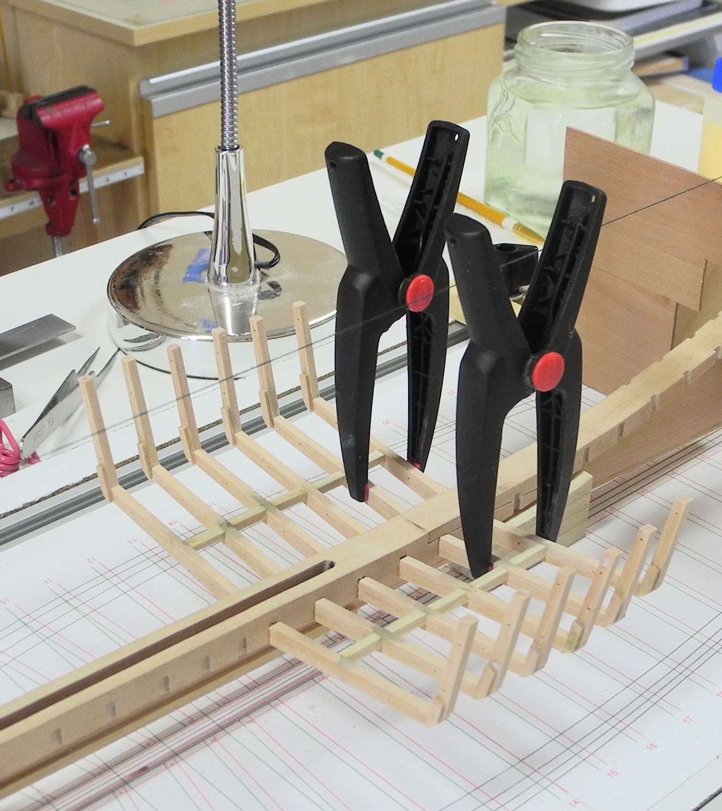
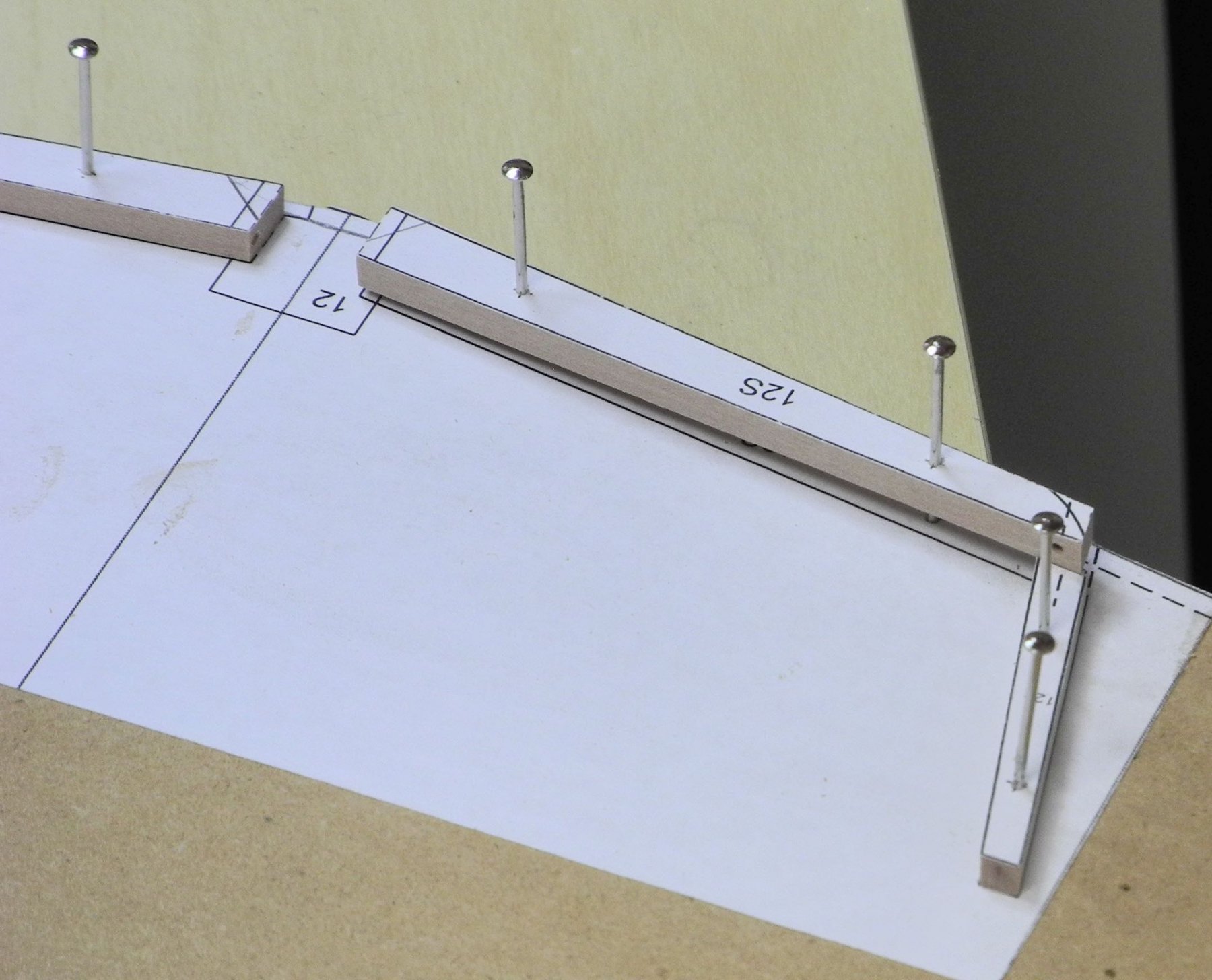
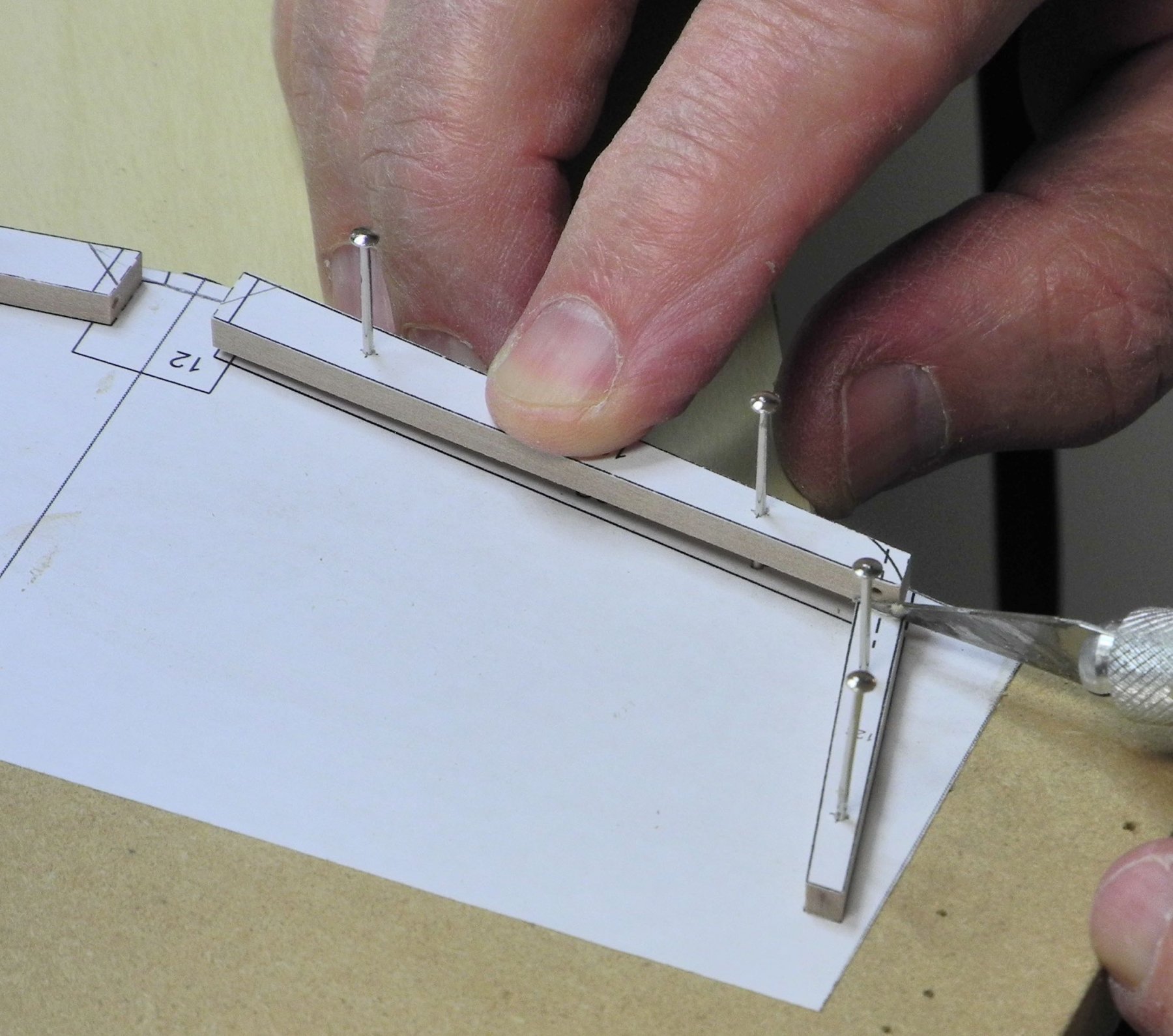
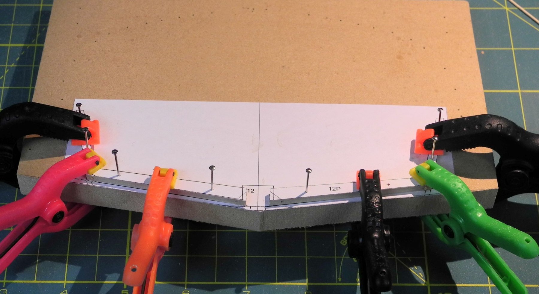
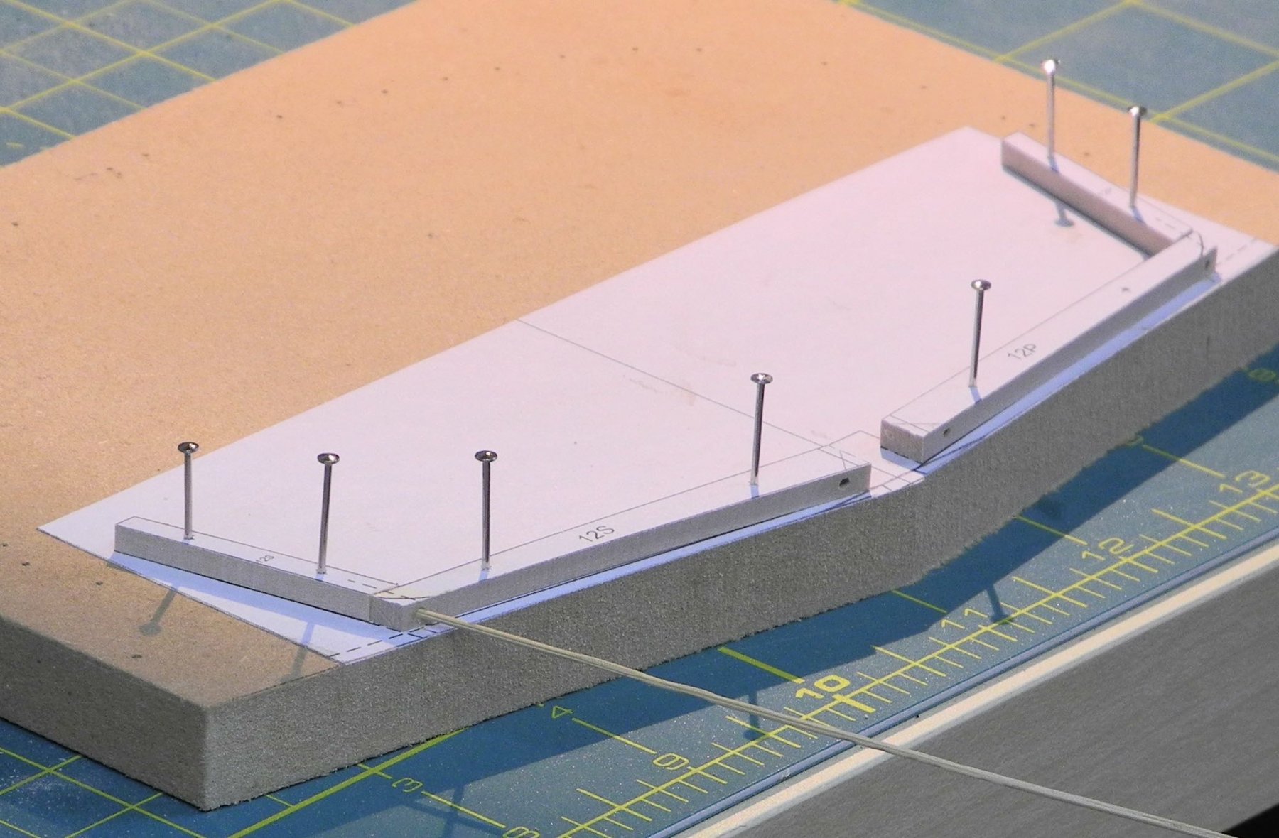
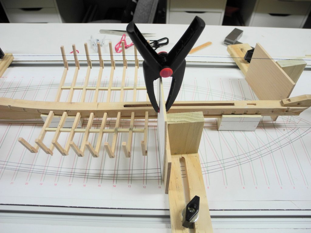
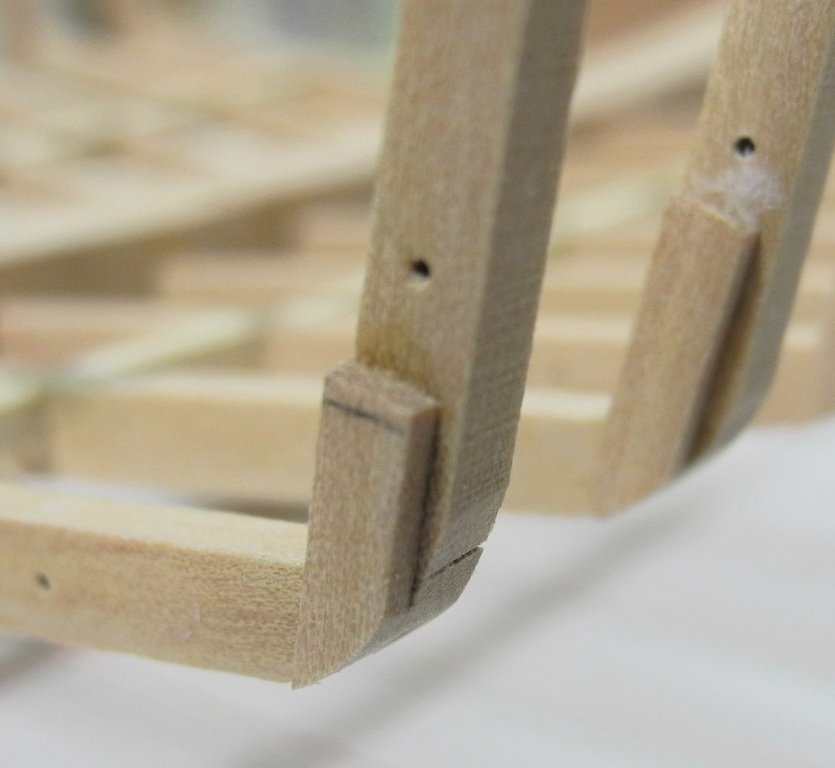
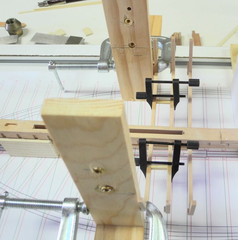
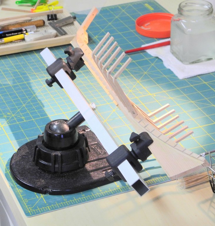
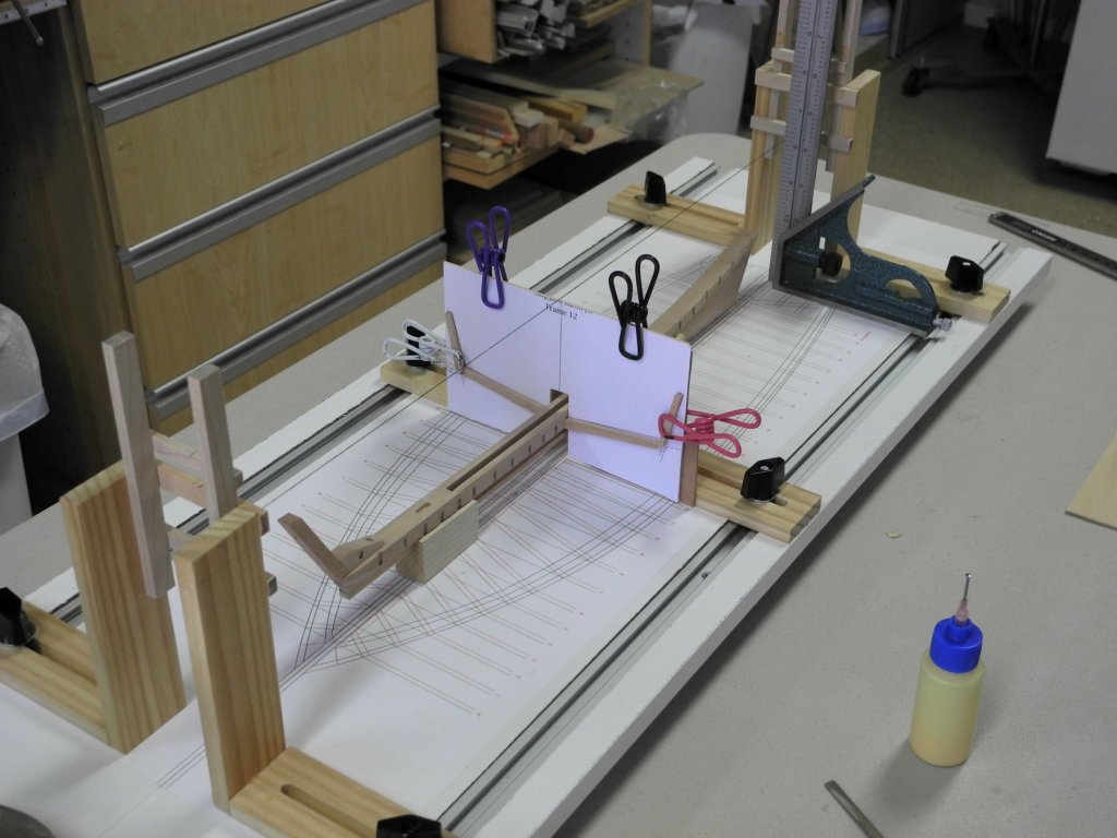
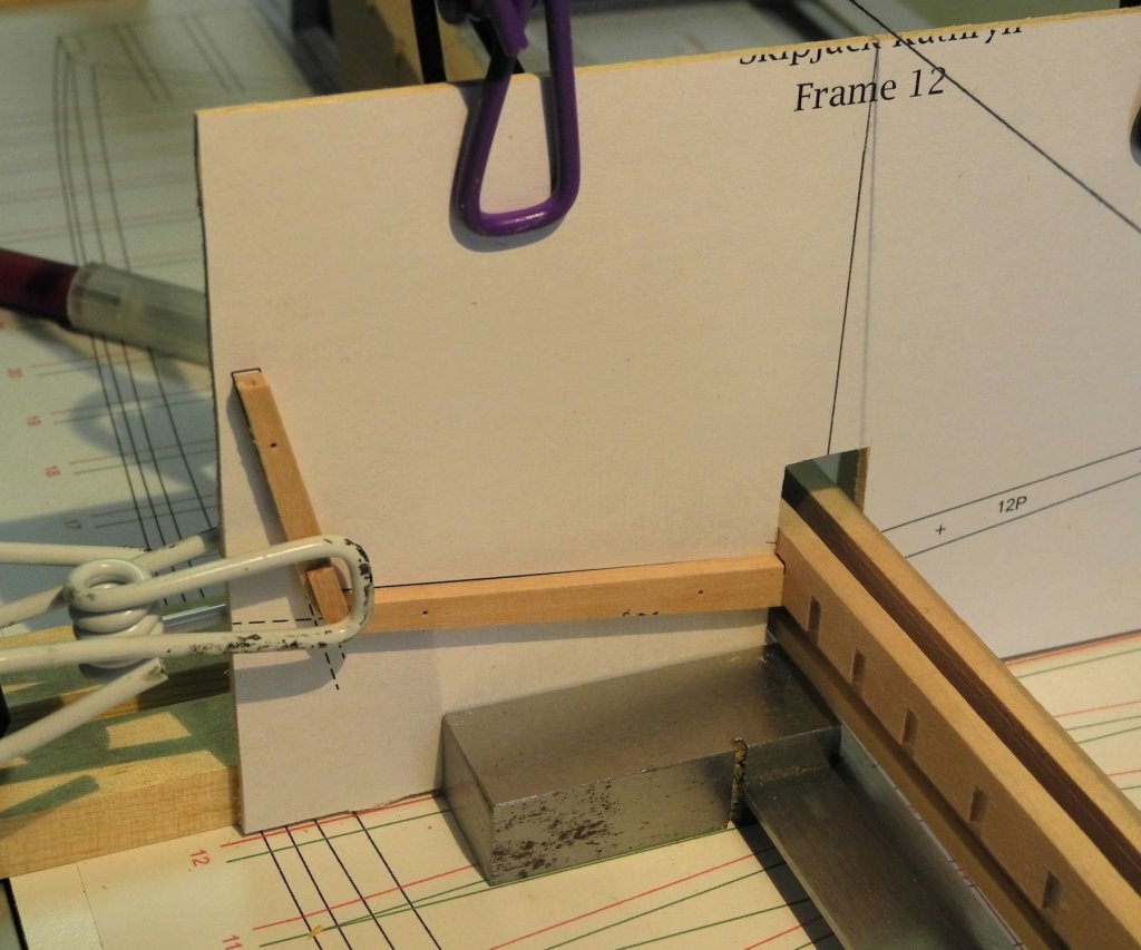
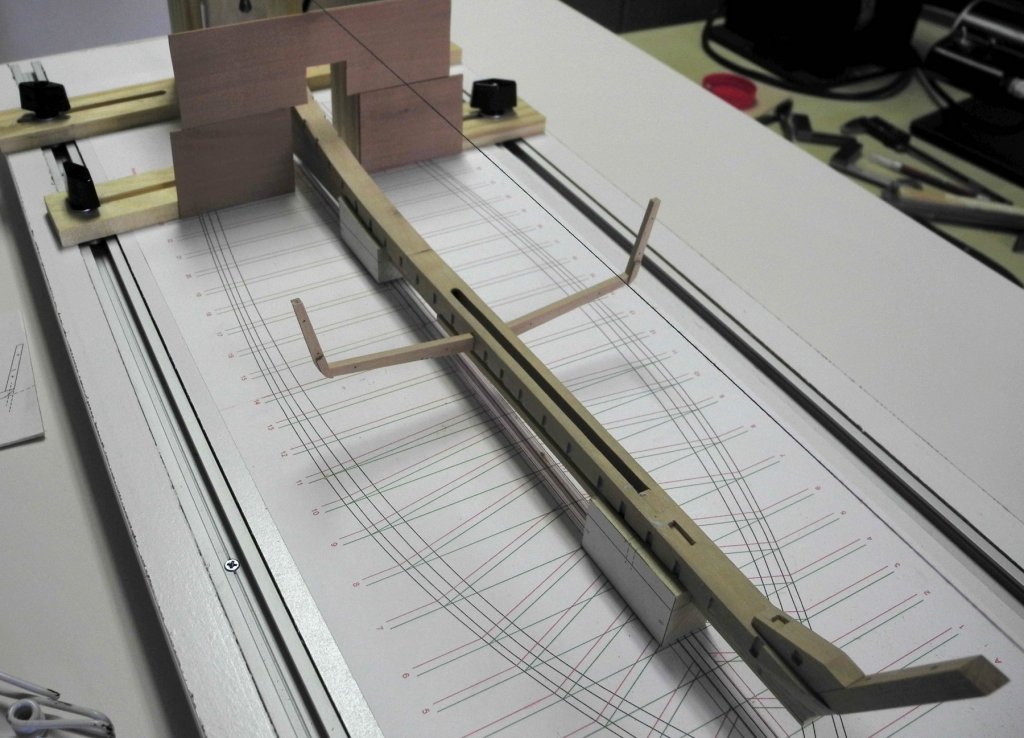
Part 8 – Frames, cont’d Framing Kathryn has been continuing – albeit slowly. There have been a lot of other activities interfering with the modeling work, so there hasn’t been as much progress as I would have liked. It quickly became apparent that the model’s frames are very delicate, and some additional steps were needed to strengthen them. This resulted in some additional structures that are not in the actual boat, but these structures will be hidden by planking and shouldn’t cause any issues. The first such structure was the addition of a reinforcing plate at the joint between the frame floor and the frame side. This plate was added after the chine had been shaped and the glued-on drawing removed. After the glue attaching the plate to the frame had dried, the plate was then sanded to match the curve of the chine. The following photo shows one of these plates in place. The individual frames are only attached to the keelson with a minimal glue joint, so individually these frames are very easy to disturb. By tying the frames together the frame assembly would be much stronger. I decided to tie them together by using 1/8 x 1/8 stock, cut to match the distance between frames at the keelson. Since this distance varies from frame to frame, the braces needed to be measure individually. They are then installed at approximately the midpoint of the frame floor to join the frames together. The first frame installed – frame 12 – was held perpendicular to the keelson by the c-clamps shown in the following photo, and then the subsequent frames were joined to that frame via the braces. The c-clamps were left in place until the first 4 frames were joined and the glue set. The first 4 frames were very stable after the glue had cured, and didn’t need to be held in place for installation of bracing for subsequent frames. It was easier to use the long-nosed spring clamps for this work, rather than the miniature machinist clamps used in the prior photo. As described in the prior post, structural bolts would be used to fully secure the frames to the keelson, and pilot holes for these bolts were drilled as part of the construction of the frames. After the installation of the first six square frames (12 through 17) was completed, it was time to insert the first set of structural bolts. The model was removed from the shipway and placed in an adjustable keel clamp. This clamp was positioned so that the pilot holes were visible. This allowed drilling through the pilot holes and into the keelson, as in the following photo. Pieces of 3/64 brass rod were then epoxied into these holes to serve as structural bolts. While the model was in the clamp, the forward edges of the mortises for the cant frames were angled to allow the cant frames to be properly positioned. This work was performed with a diamond bit in a rotary tool. The middle 8 square frames are now in place. Since each half of a frame is a separate installation, this is the equivalent of 16 frames having been installed. The frames installed so far have not needed any dubbing (shaping) to allow the planks to lay flat against them. The remaining seven square frames in the rear of the model will need shaping. In addition, the forward eleven frames are cant frames, which will require a modified installation procedure. These topics will be covered in the next post. Thanks everyone!
- 878 replies
-
- 27
-
-
Thanks Tom and Patrick for the birthday greetings. Had a great day. Thanks Ed. The combination makes the drilling much easier.
-
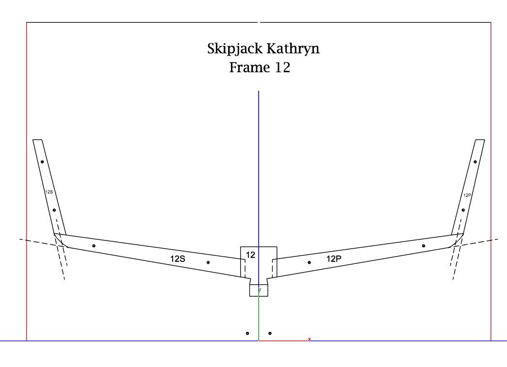
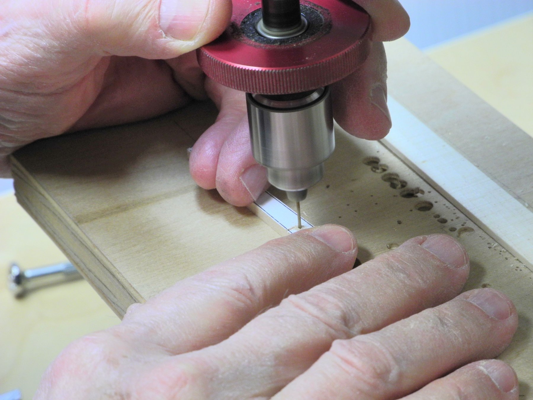
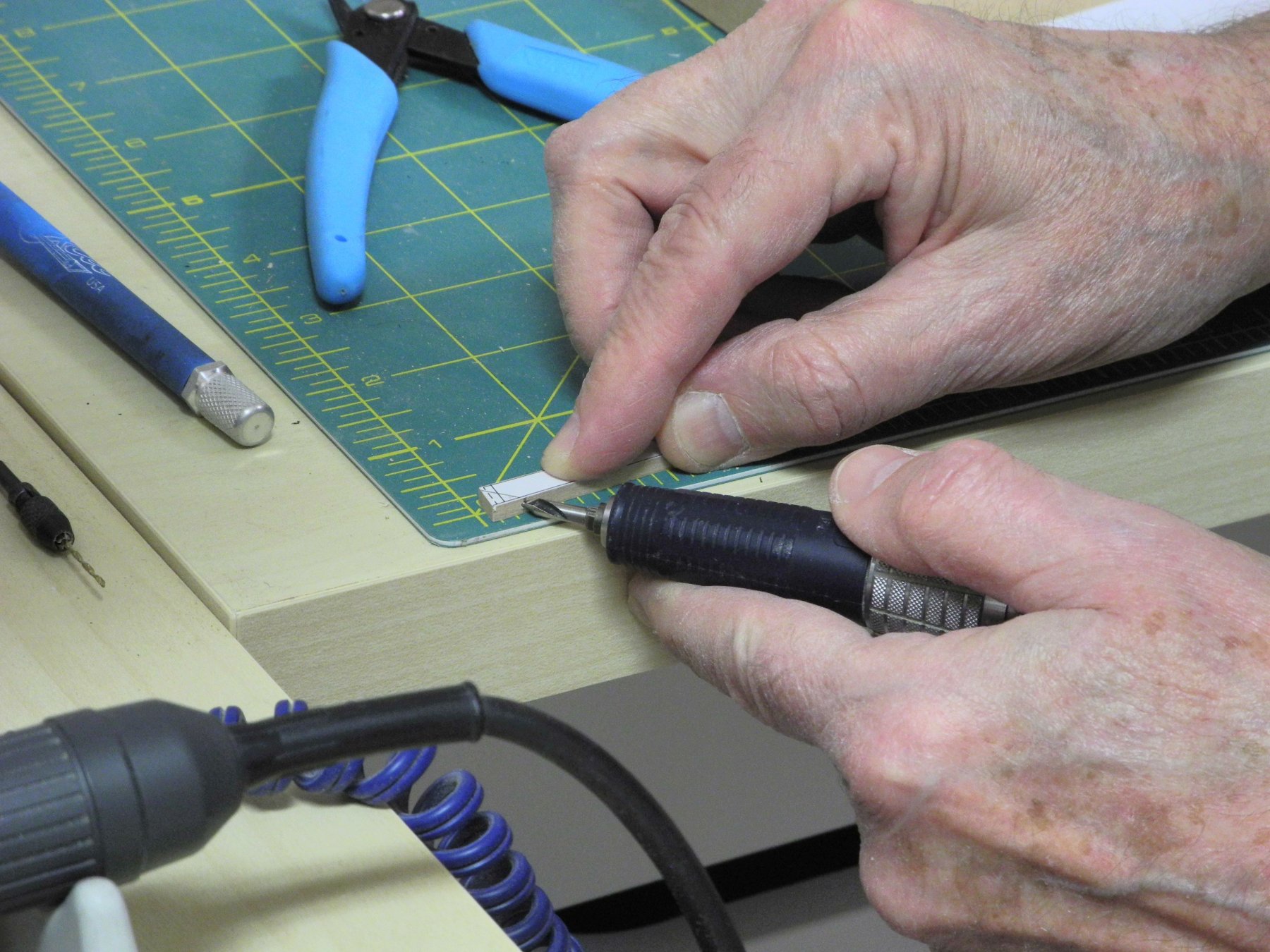
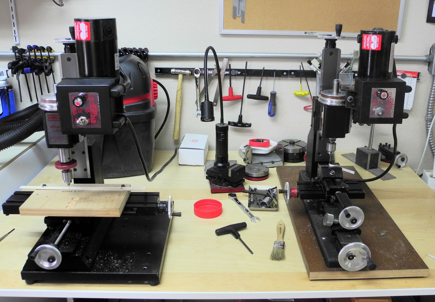
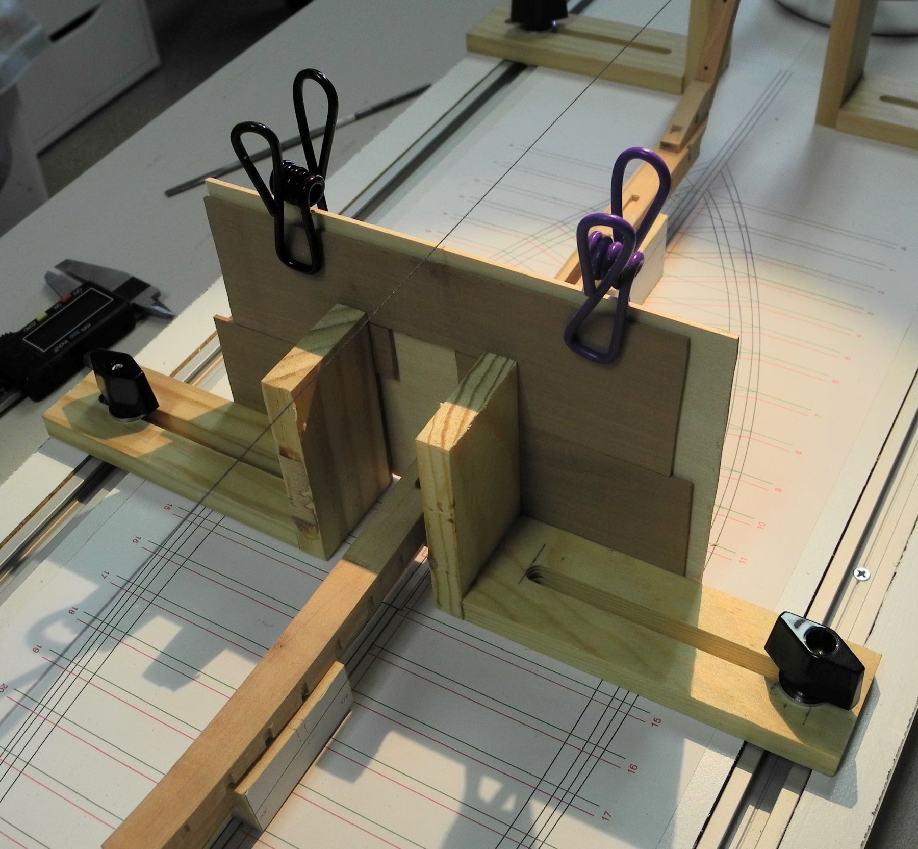
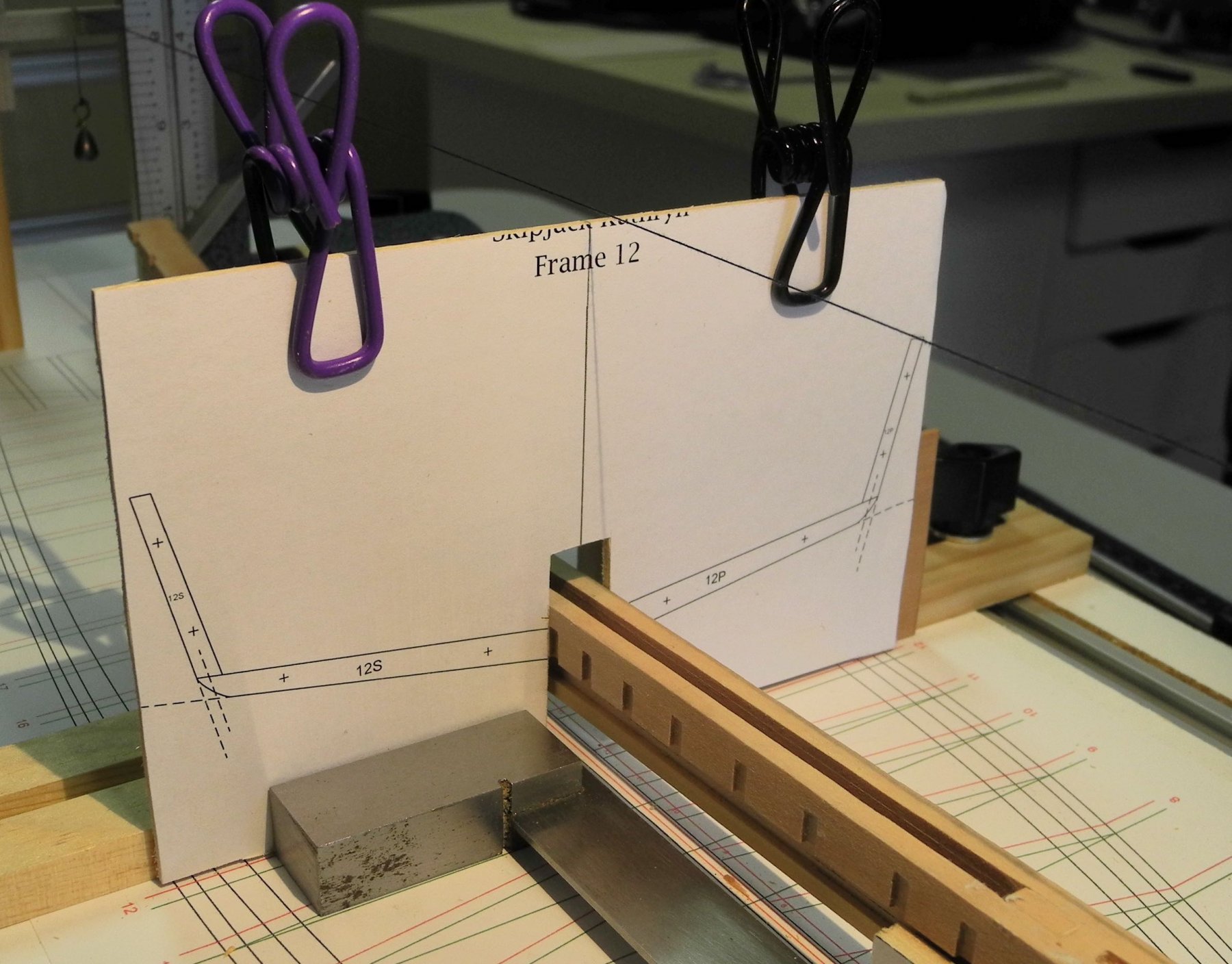
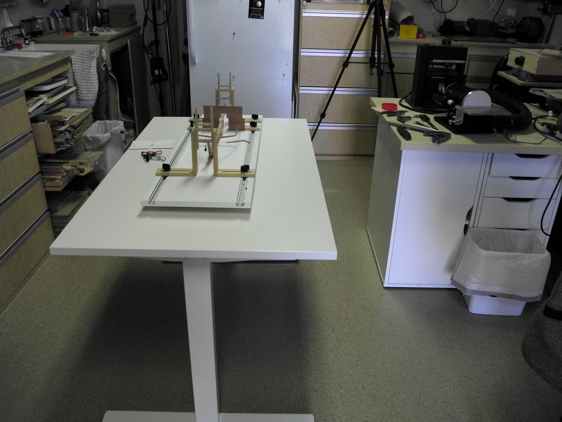
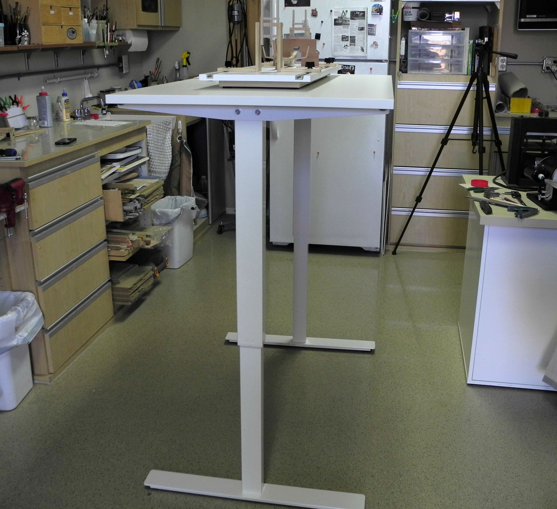
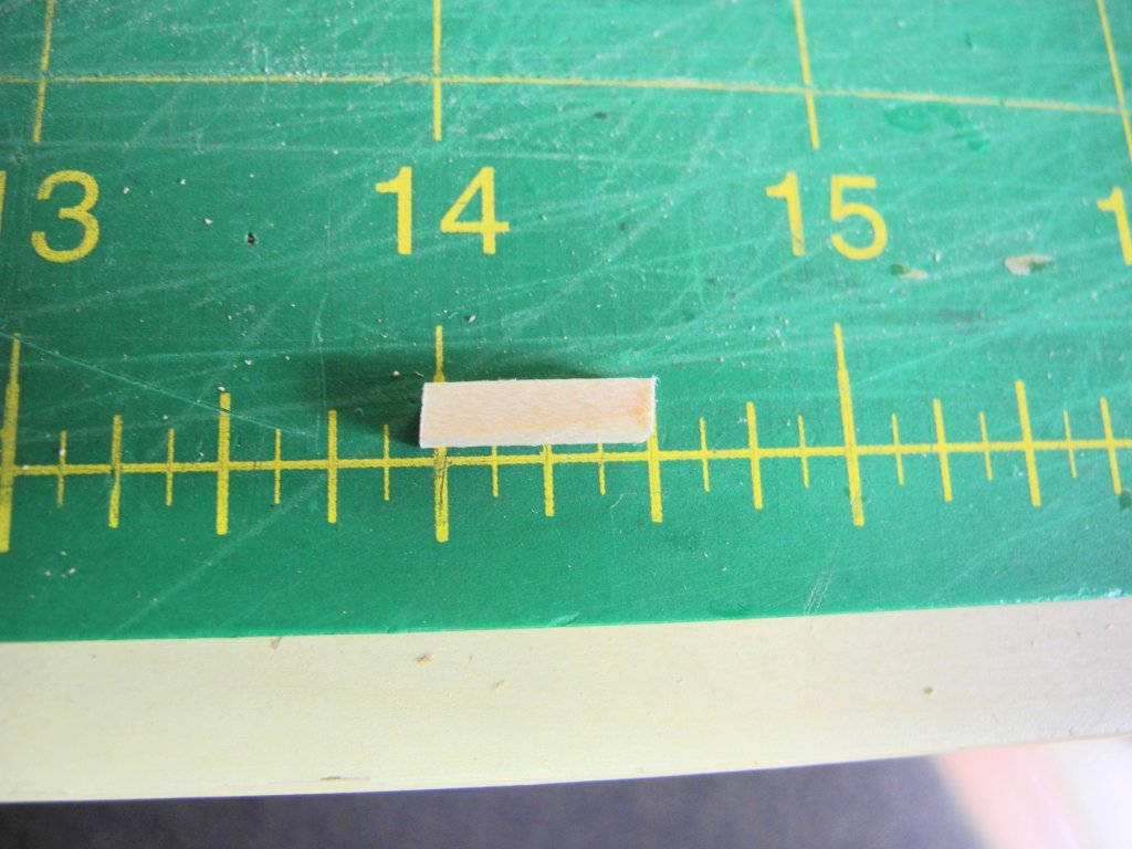
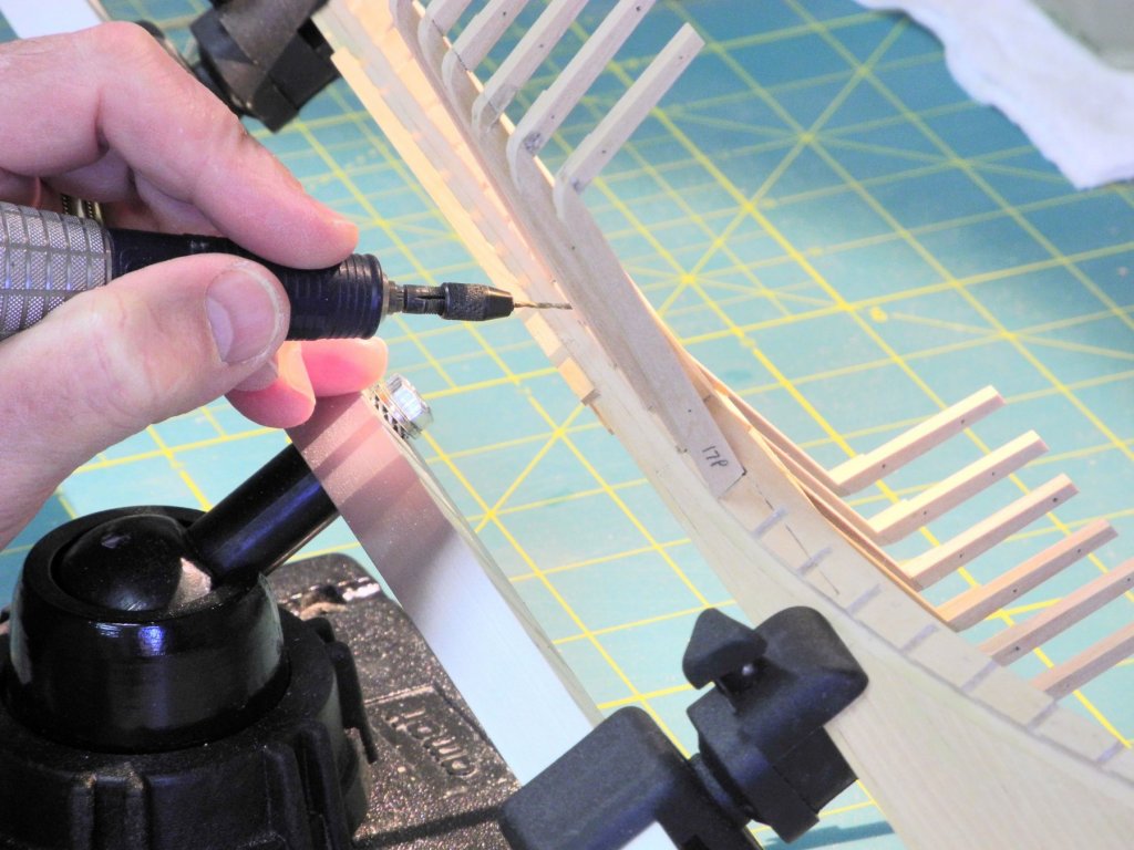
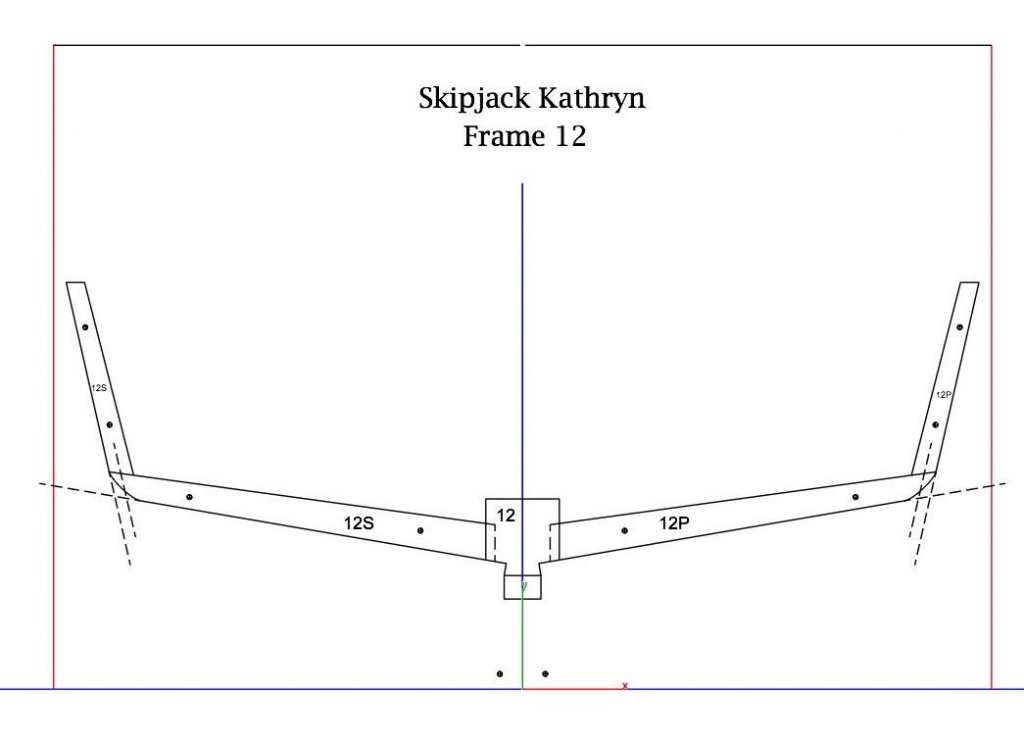
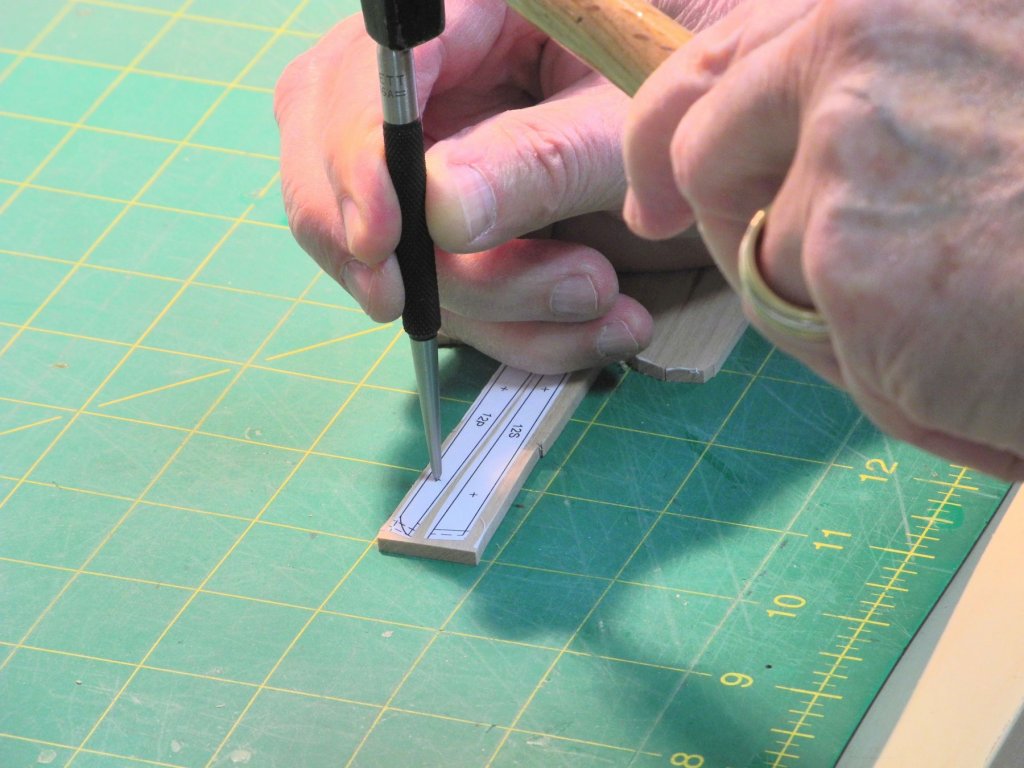
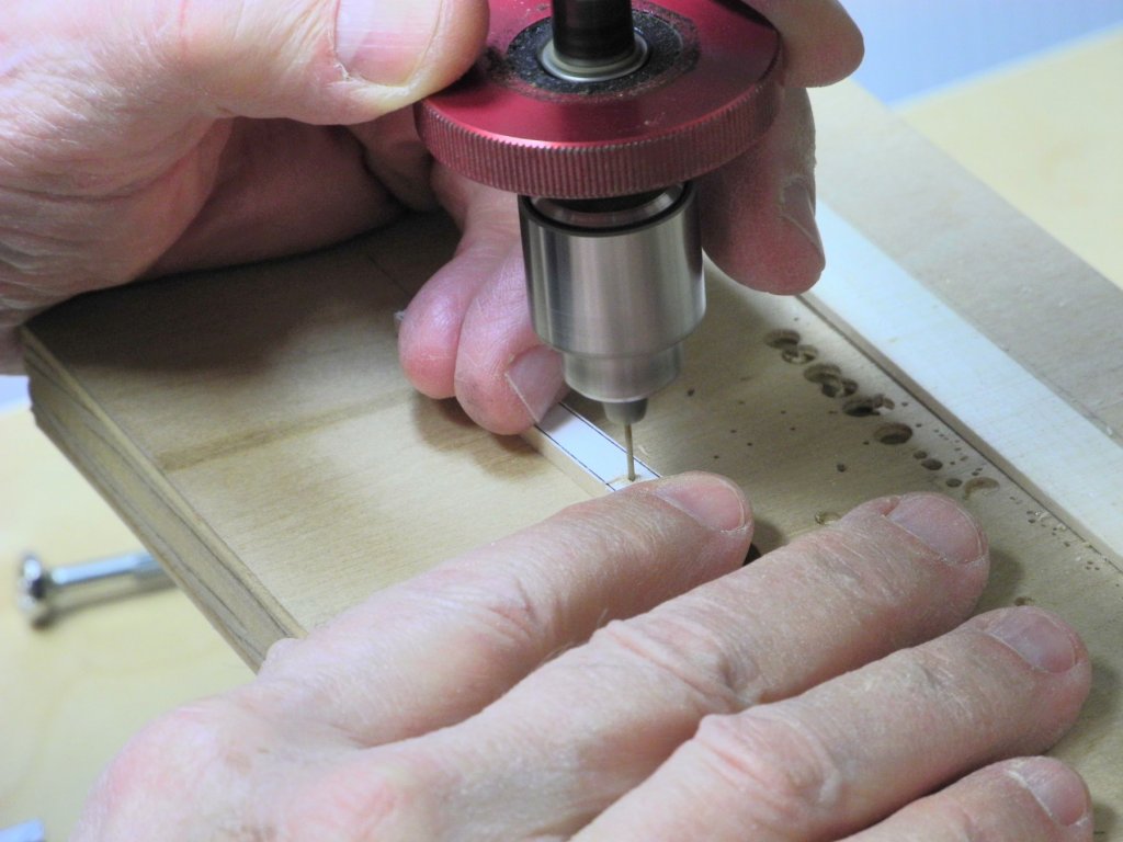
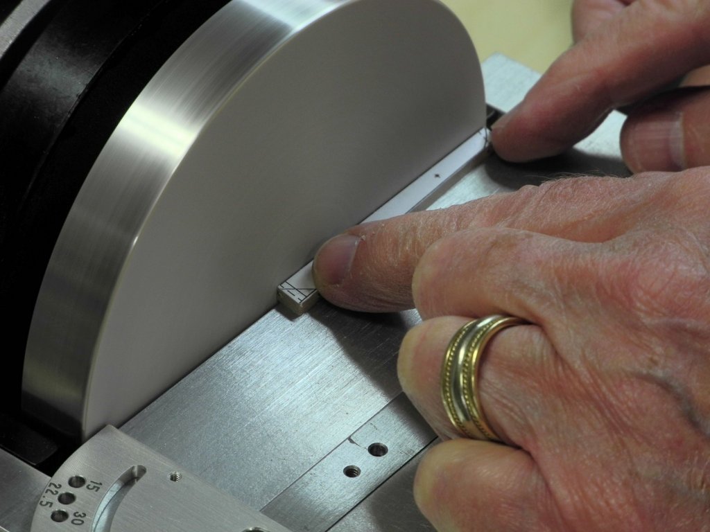
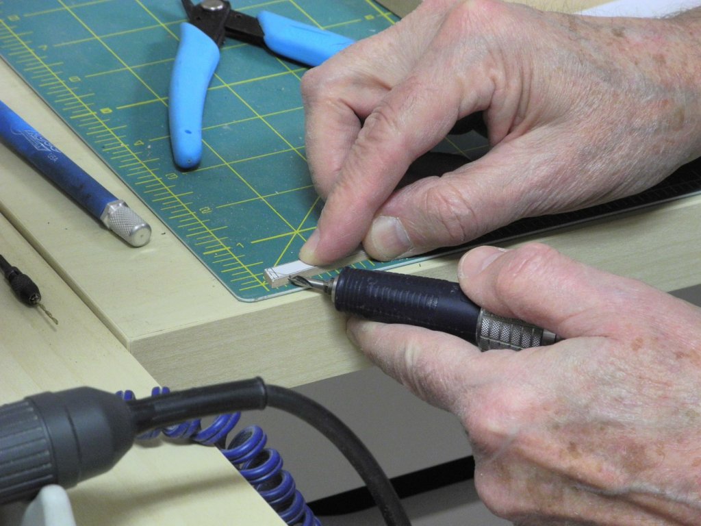
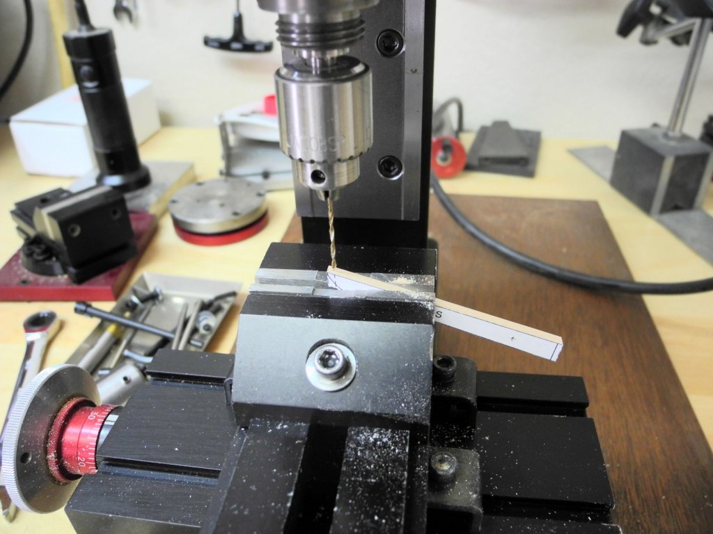
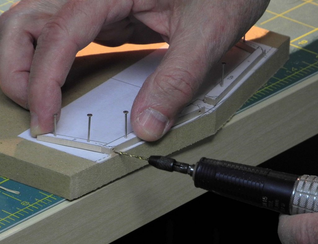
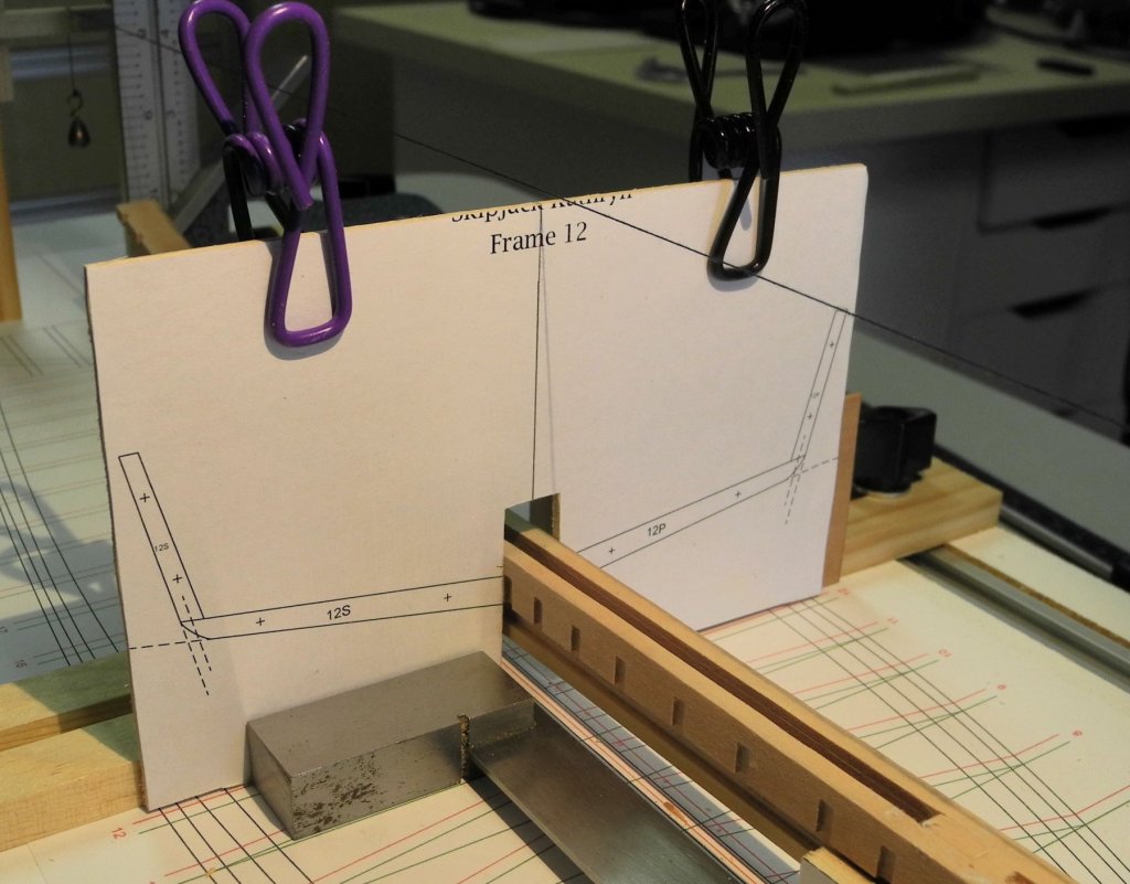
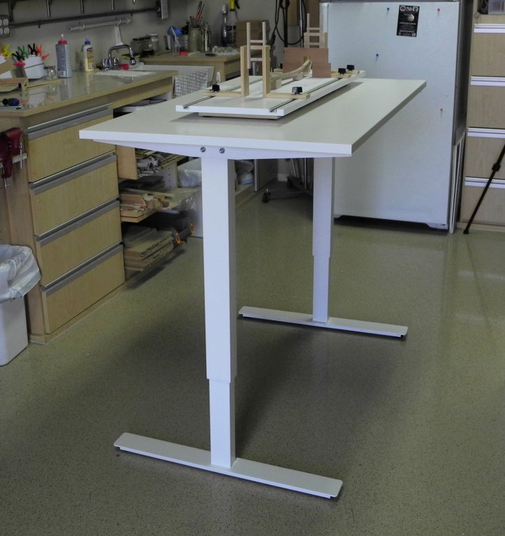
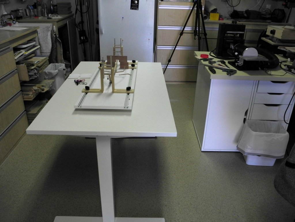
Part 7 – Frames The HAER documentation says that Kathryn’s frames are ‘highly irregular’, rather than giving dimensions. After measuring the frames in several of the drawings I decided to use a sided dimension of 4” and a moulded dimension starting at 5” at the sheer and increasing to 8” for most frames. This makes the frames of the model 1/8” thick, and varying from just over 1/8” to ¼” in the moulded dimension. All frames are single frames, so on the model they will be quite fragile until supported by the interior and exterior planking and other components. Since Kathryn’s sides and bottom are flat, there are no curves to contend with in the frames – other than the rounded chine. The following is the drawing for frame 12 – the forward-most square frame: Pin-indexing is used to ensure the pieces of the frame line up with the drawing. EdT in his Young America build log gives a good description of pin-indexing, and I also included it in my Dunbrody build log, so I won’t go into a lot of detail here. Individual frame pieces as well as the pinning template for the frame are marked using a prick punch And are then drilled using the Sensitive Drilling Attachment on the milling machine. The frame pieces are then trimmed to the printed lines using the disk sander. The frames will be very delicate, and there won’t be much glue surface keeping the frame components together or keeping them attached to the keelson, so some additional reinforcing is required. The frames will eventually be secured to the keelson with structural bolts, and the joint of the frame pieces will be reinforced by dowels, so pilot holes need to be drilled. The holes for the structural bolts are at an approximate 45 degree angle, so these holes need to be started with a center drill as shown in the following photo. The pilot holes are then drilled in the frame components. The drill used for pin indexing is a #63 drill, and the best approach is to use the sensitive drilling attachment for this drilling. However, the drill used for pilot holes for the reinforcing bolts and dowels is a #55, and the best approach for this drilling is to use the z-axis hand-wheel to get sufficient force in the drilling. This would normally mean constant changing of drills and chucks, but I’m fortunate to have another solution in my shop. I’ve tried miniature drill presses, but have not been happy with the ‘less expensive’ options (less expensive until an x-y table is added). Recently, Sherline offered a discount on the milling column for the lathe. This attachment serves very nicely as a second drilling station (or mill if necessary), so I now have the sensitive drilling attachment with the #63 drill in the milling machine, and a chuck with a #55 drill in the milling column on the lathe and have no need to change drills or chucks in the middle of the process. Constructing the frame consists of aligning the pieces by laying the bottom piece on top of the side piece (using the pins for alignment) Then using a hobby knife to mark the joint on the side piece of the frame. After the side piece is trimmed to fit using the disk sander, the pieces are then glued in place and left to cure. When the gluing is completed, the hole for the reinforcing dowel is drilled into the side piece of the frame. The dowel is glued into the frame and clipped off. Since the frames are mortised into the keelson on each side, aligning the frame on the keelson requires that each side is aligned separately to allow for possible mis-alignment of the mortises. A jig is used for this purpose. This is the same jig that was used to align the Dunbrody frames. In addition to the jig, a template for the frame, consisting of the frame drawing cemented onto a flat piece of 1/16” thick basswood, is clamped to the framing jig and aligned with the centerline. The frame piece is clamped to the framing template while the glue attaching the frame half to the keelson cures. The same process is followed for the opposite side of the frame. The following photo shows the first frame (#12) installed. Only 25 frames to go. One last item: I wanted a modeling setup that would allow me to work on all sides of the build without turning the shipway. It would also be ideal if I could raise or lower the model depending on what was being worked on at the time. I was able to find an adjustable table in IKEA – known as a Skarsta sit/stand table. Using a simple hand crank, the table extends from a minimum height of 27.5” to a maximum height of 47.25” My old back is very grateful for the working height!! Thanks everyone (and thank you IKEA!)!


- 878 replies
-
- 31
-
-
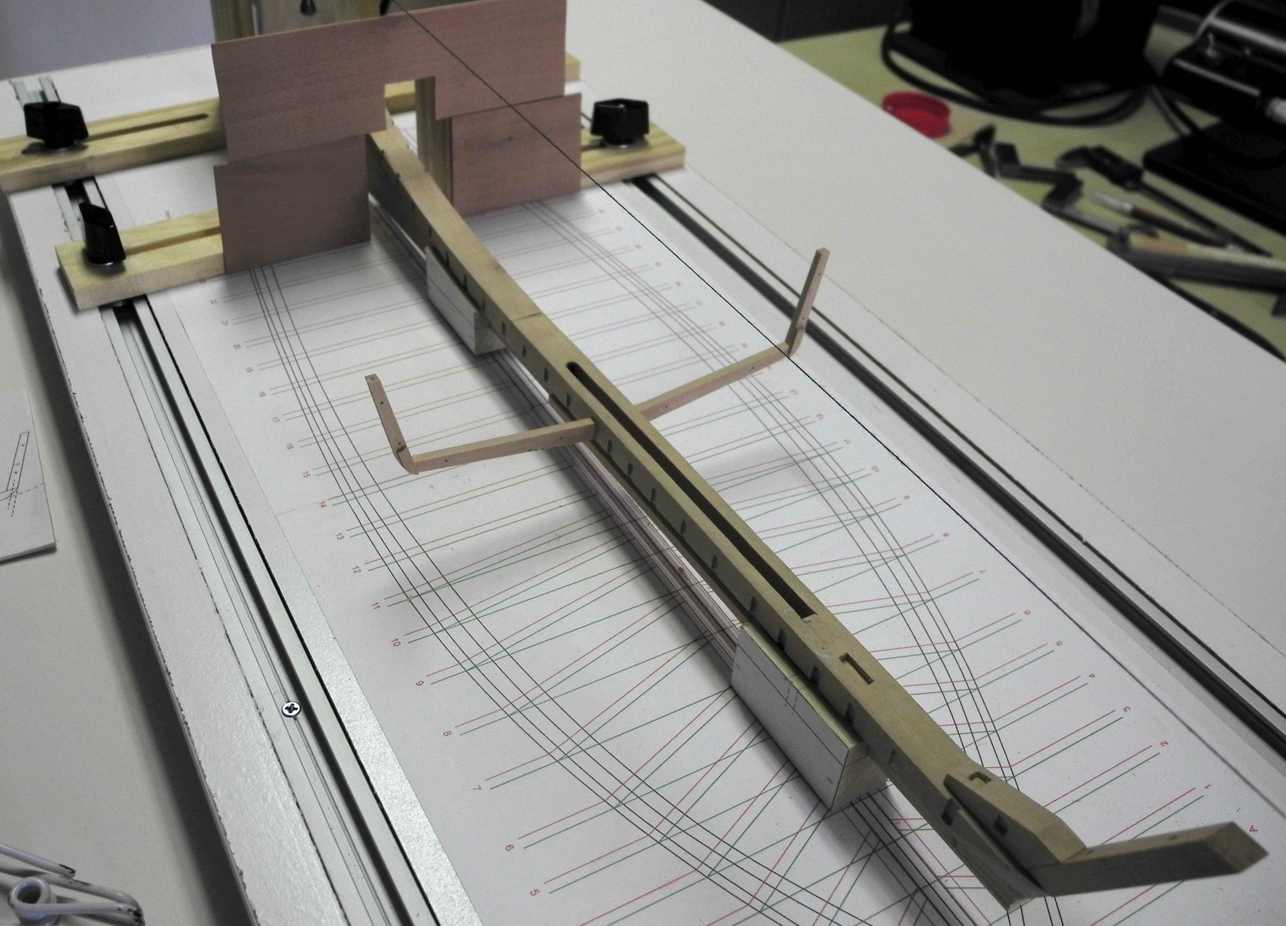
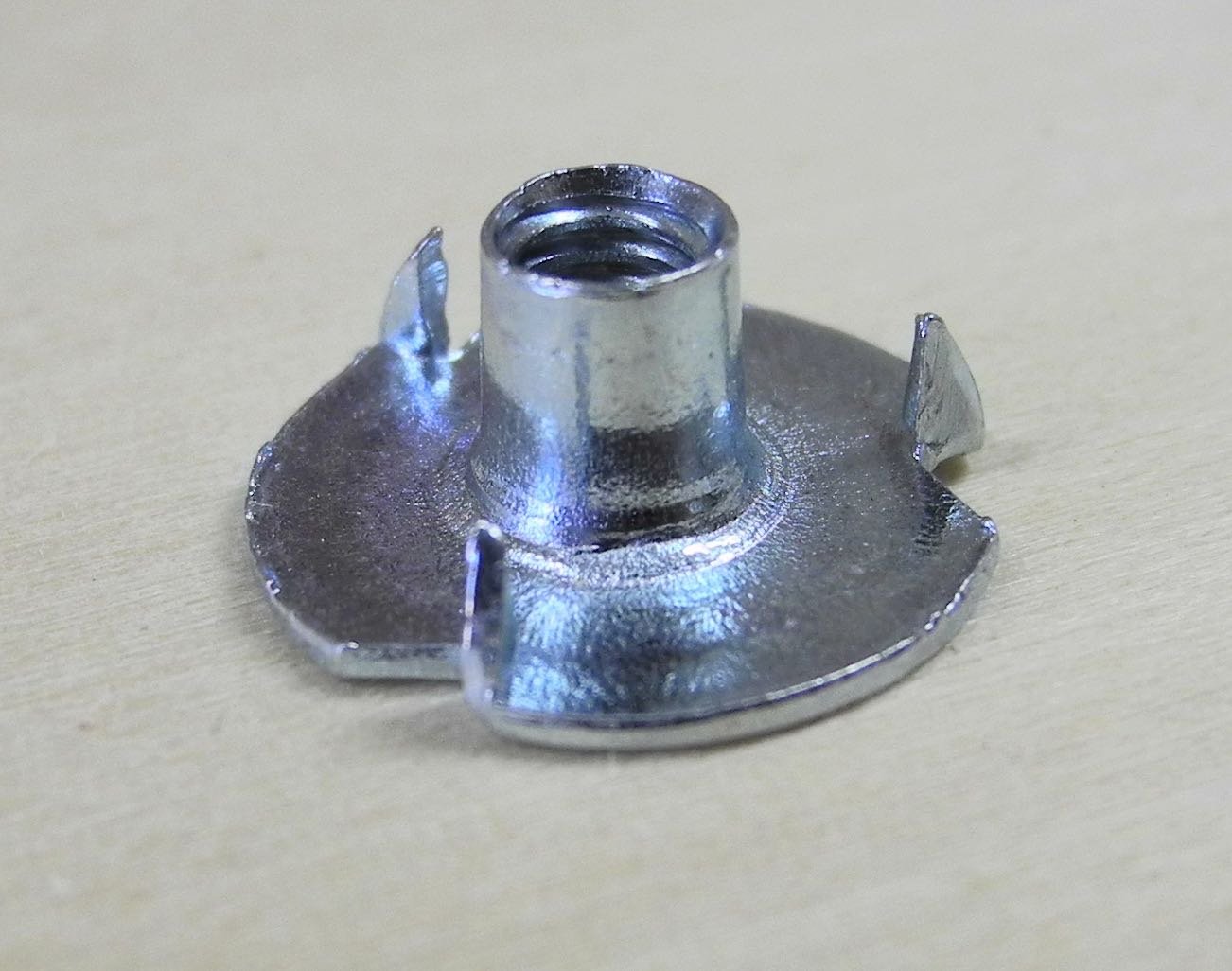
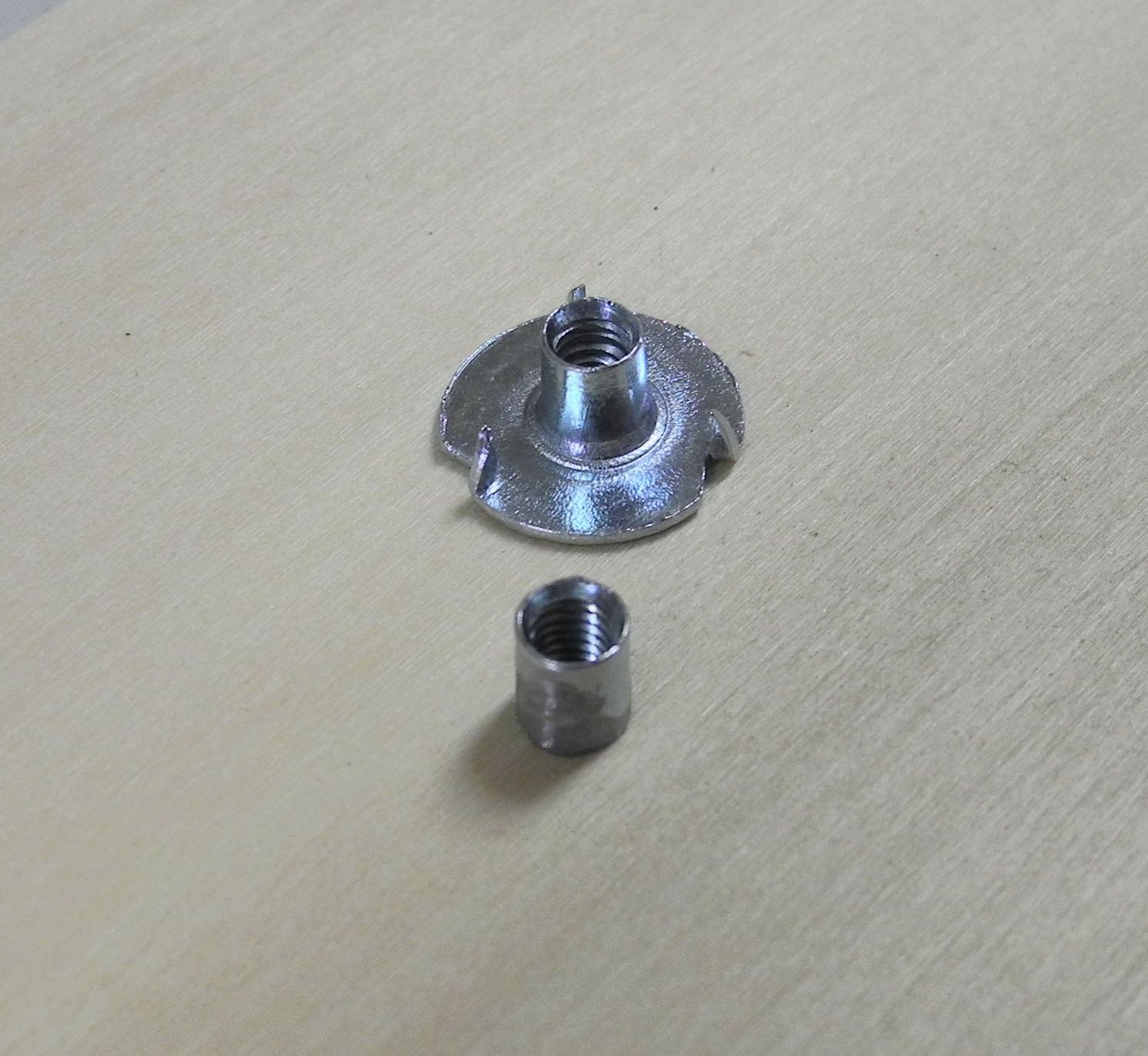
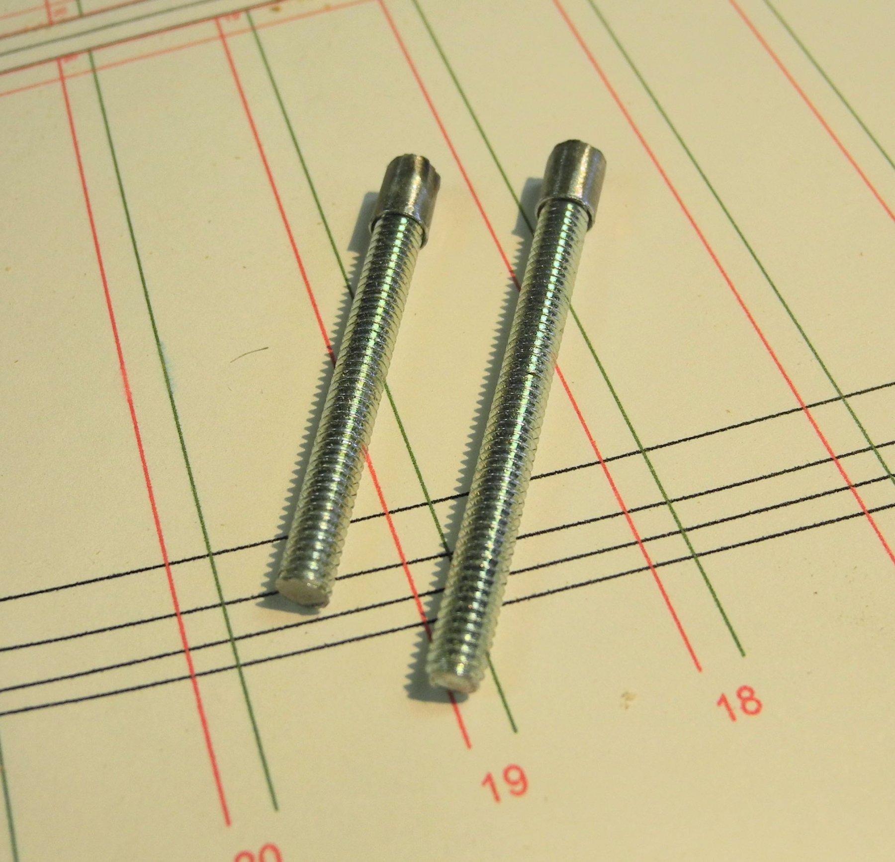
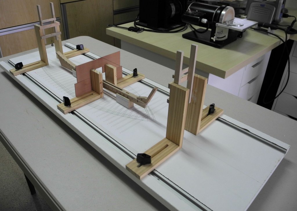
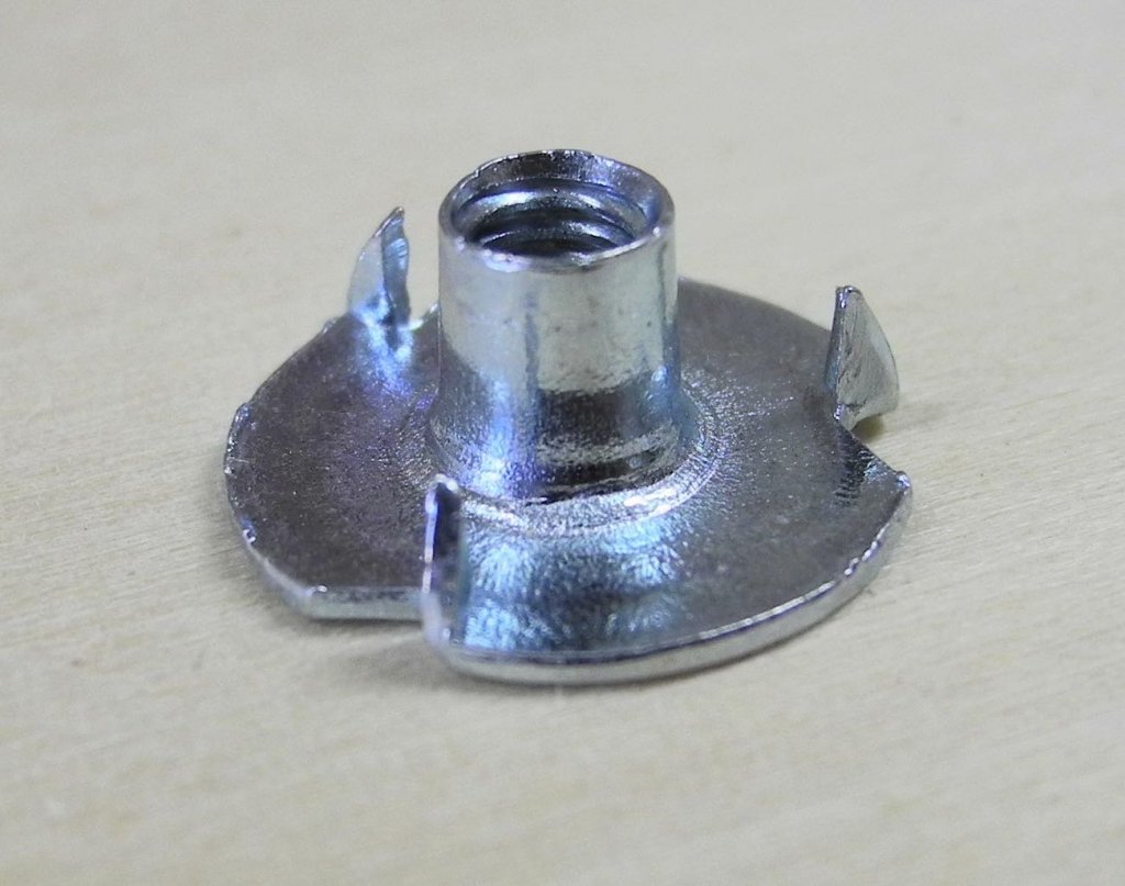
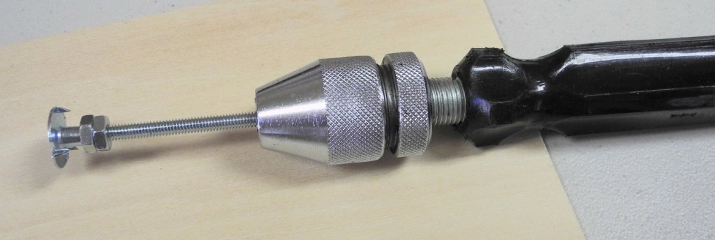
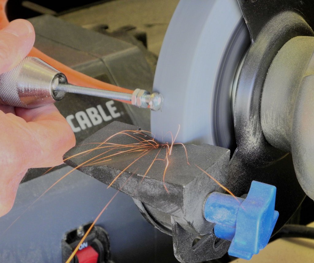
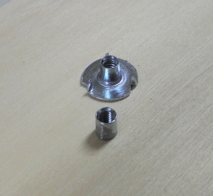
Part 6 – Shipway and Mounting It’s been a little while since the last post – due to some challenges. In the last couple of posts I’ve shown the model shipway for Kathryn in use, but haven’t described it in any detail. The shipway is constructed using a 12” x 48” x ½” melamine shelf, routed to take the Veritas T-Slot Tracks from Lee valley. These tracks allow the use of the ½ thick shelving – other tracks would require a thicker board. This is the same arrangement as used on the Dunbrody build, but is based on a longer shelf since Kathryn will be longer than the Dunbrody sectional model. The devices at each end of the shipway are the jigs used for holding the centerline, and are the same as used in the Dunbrody build. The other fixture in the center of the shipway is a jig used for setting the frames – it’s the same jig as was used for Dunbrody, but will be used in a different manner. Its use will be described in a future post when frame installation is covered. Kathryn is mounted using bolts that run through two spacers that were cut to hold the model at the proper angle. The initial intent was to thread the shoe/keel/keelson combination to hold the mounting bolts to the hull. However, when I started mounting the frames it became apparent that the model would need to be frequently removed from the shipway during the framing process. Obviously the threaded holes in the wood components would probably not stand up to frequent jostling, so a different approach was needed. Since there was no longer any way to embed a nut in the keelson, as had been done on Dunbrody, I needed to find a way to embed a threaded sleeve through the very narrow keel (8”, or ¼” at scale). I decided to use an 8-32 pronged t-nut as shown in the following photo. The entire flange needed to be ground off, so a method of holding the nut during grinding was needed. The nut was screwed onto 8-32 threaded rod, which was held in a large pin-vise. Two hex nuts were used to keep the t-nut from turning during grinding. The flange of the t-nut was then ground away using a bench grinder. The following photos show a threaded sleeve after grinding was completed, and both sleeves screwed onto the mounting rods ready for installation. A #7 drill was the largest drill that could be comfortably used to enlarge the holes in the keel, so the sleeve needed to be further ground to fit into the hole. The sleeves were then epoxied into the keel. The mounting bolts can now be removed without any risk to the screw thread within the keel/keelson. With the mounting work now completed framing can begin and will be the subject of the next post. Thanks everyone for following and for the continued encouragement.

- 878 replies
-
- 17
-