Mahuna
-
Posts
1,504 -
Joined
-
Last visited
Content Type
Profiles
Forums
Gallery
Events
Everything posted by Mahuna
-
 Thanks Alan. I'm enjoying trying to build Kathryn as she was originally built. Most of the work will eventually be covered up, but we'll know it's there!
 -
Thanks Brian. Looking forward to seeing you tomorrow. Thanks Popeye. I think the word 'ceiling' is a form of 'sealing' - not sure, but I think I read this somewhere. Thanks Ed. Yes - I've been missing your Young America posts. Thanks Rich. Hope you bring your Argus tomorrow. Thanks Druxey. I stay away from CA except for work like the bolting. Thanks Patrick - I appreciate the good wishes.
-
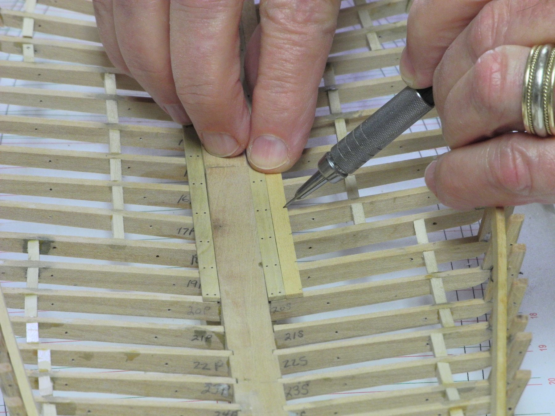
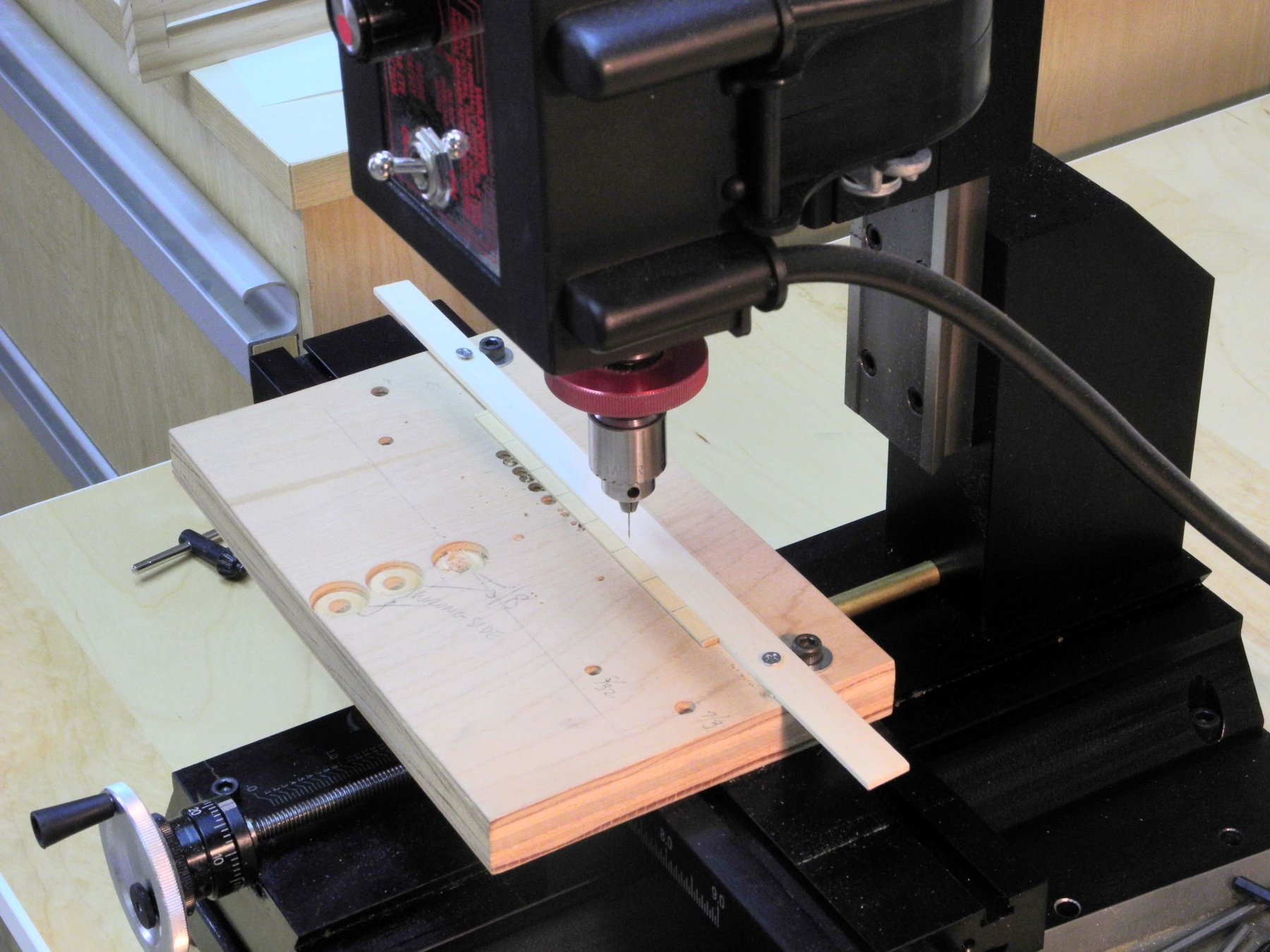
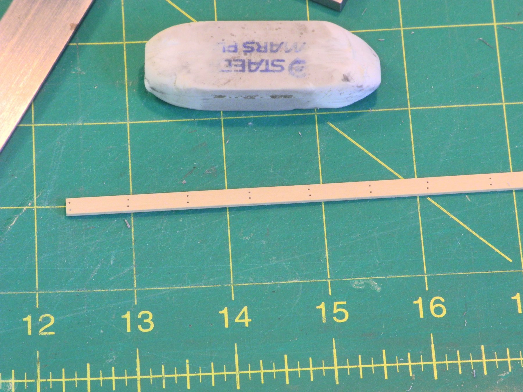
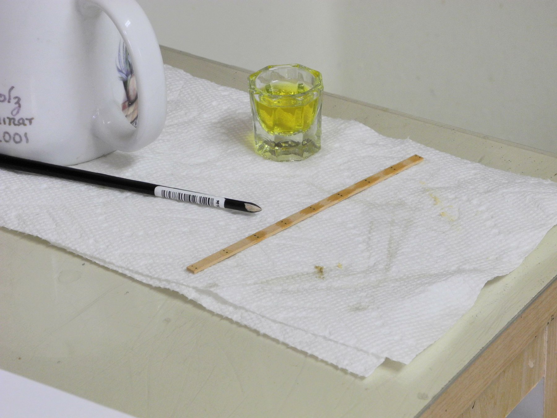
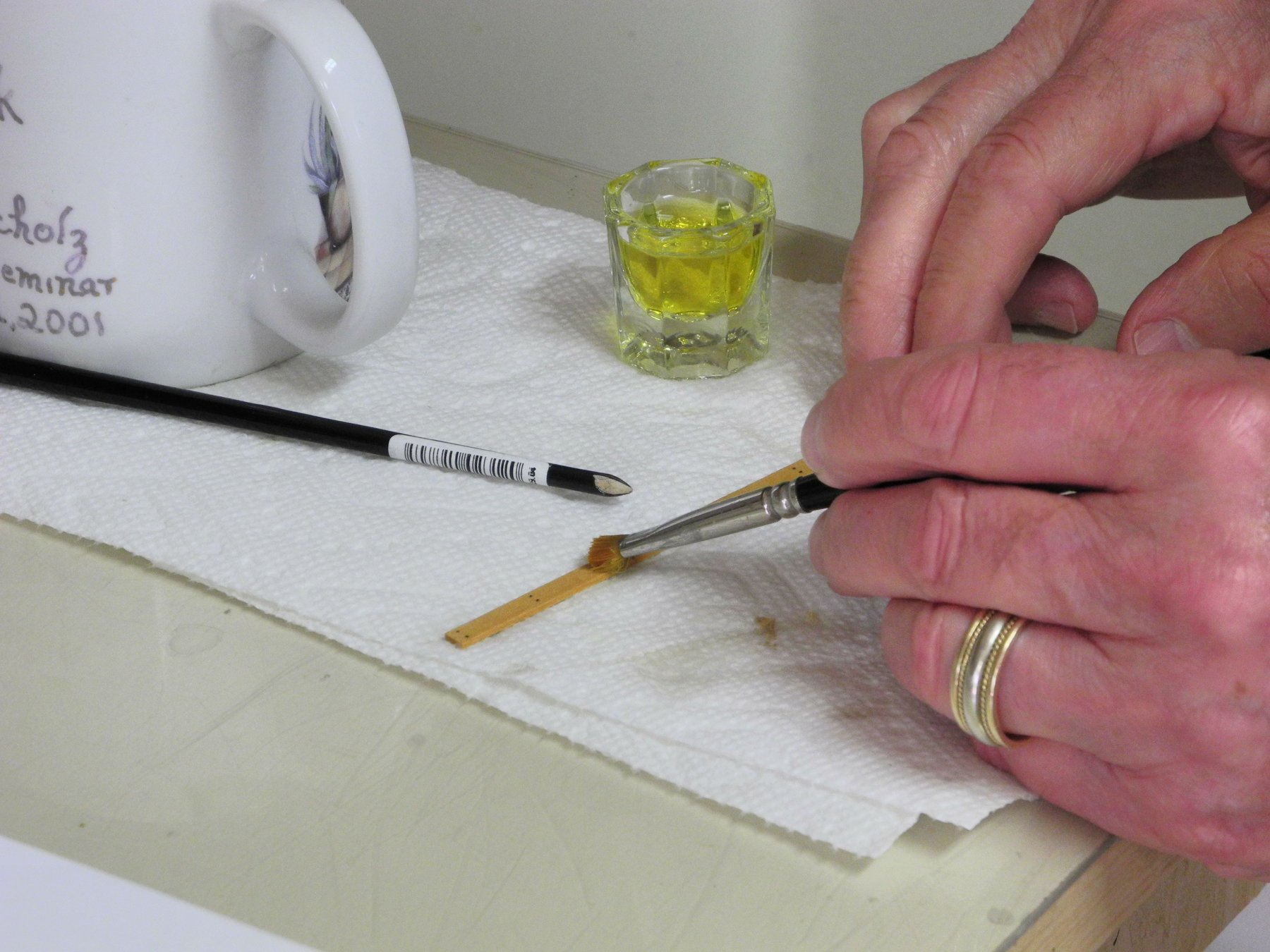
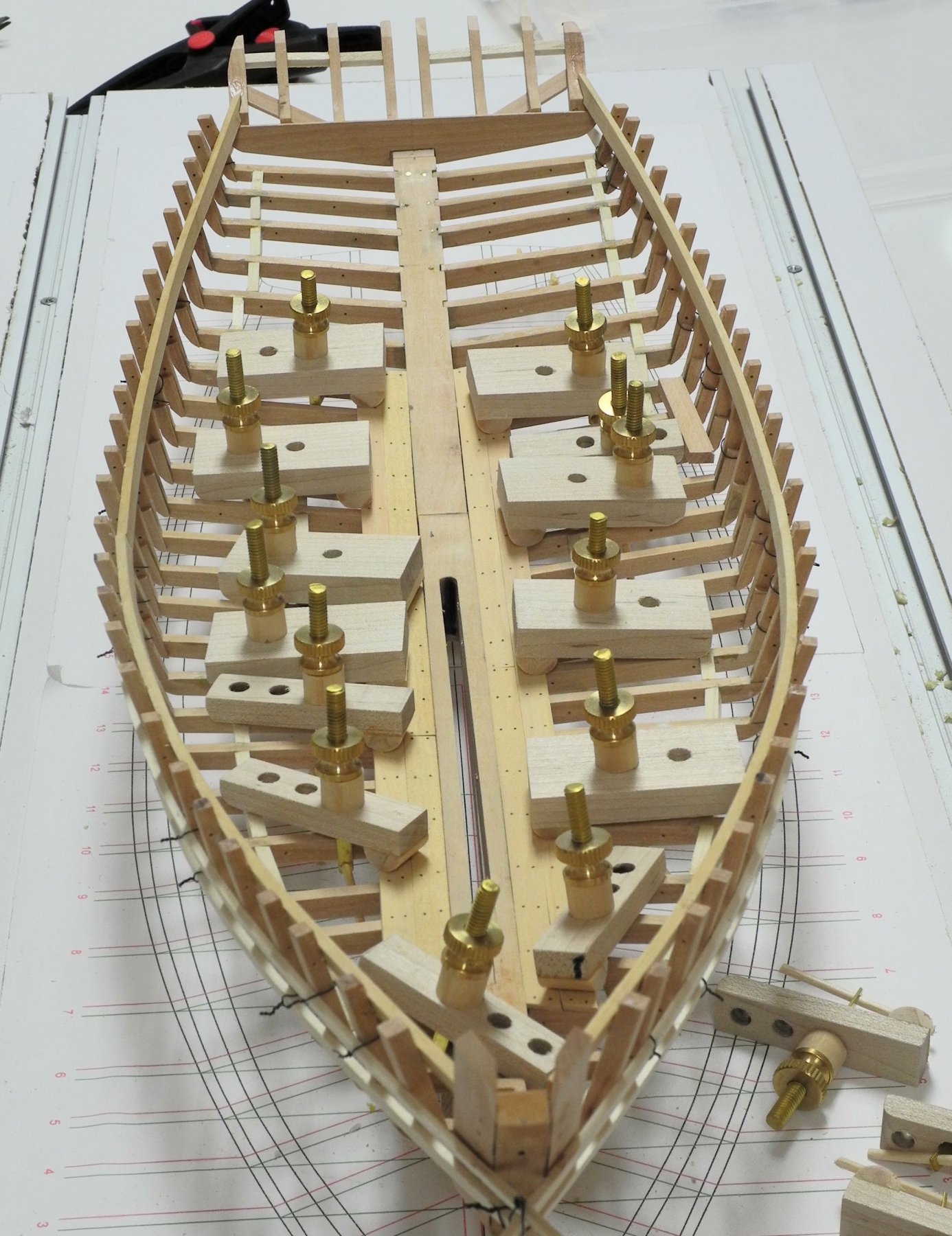
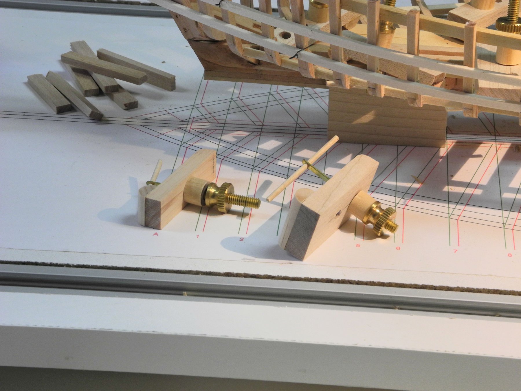
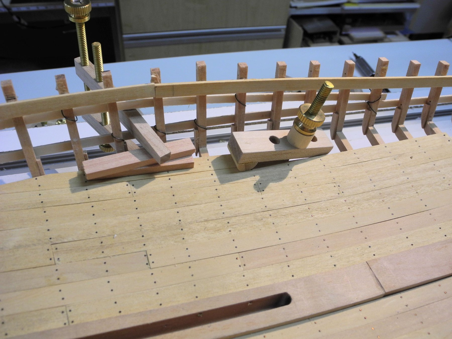
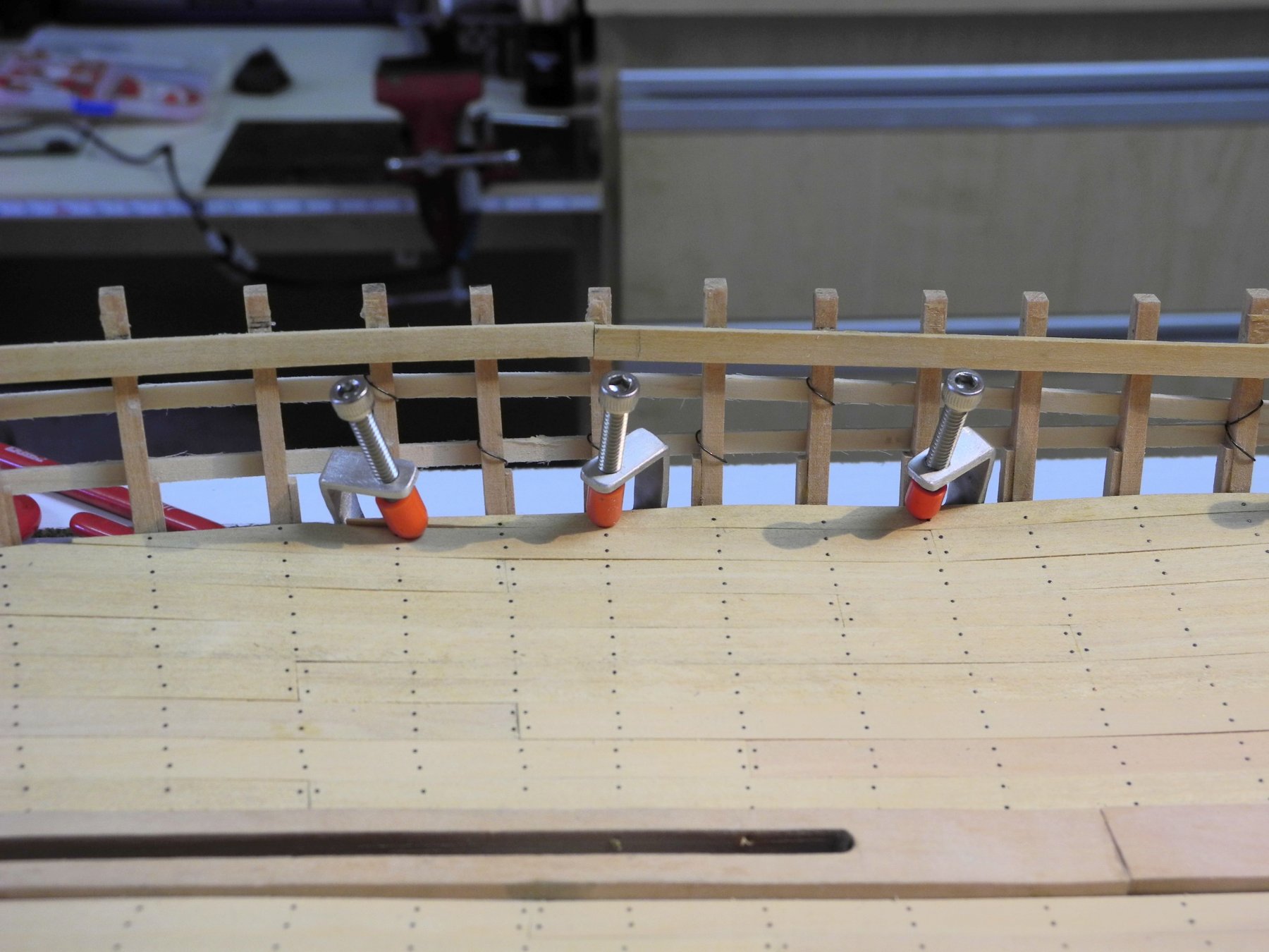
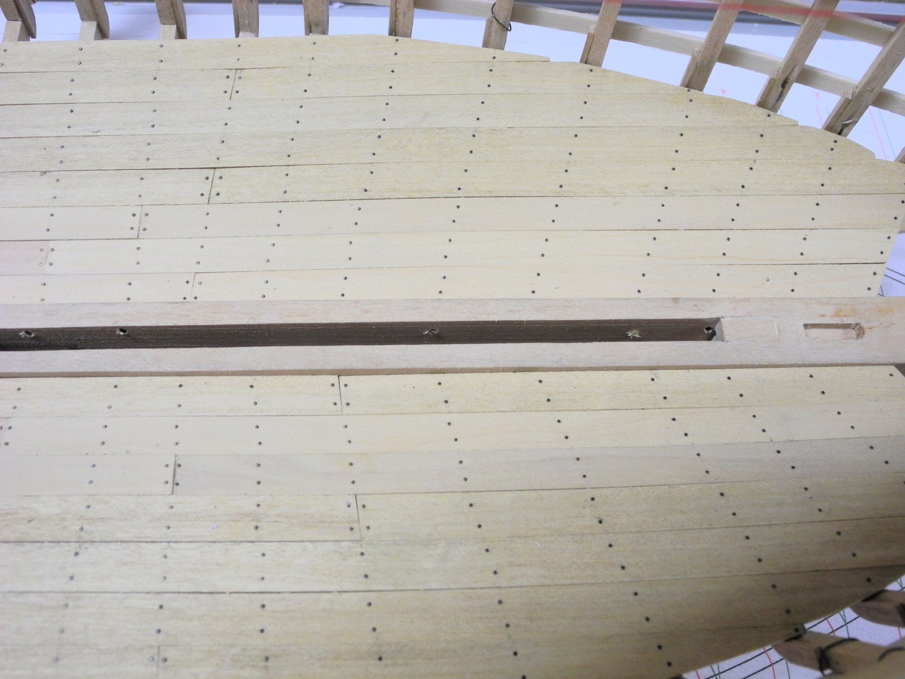
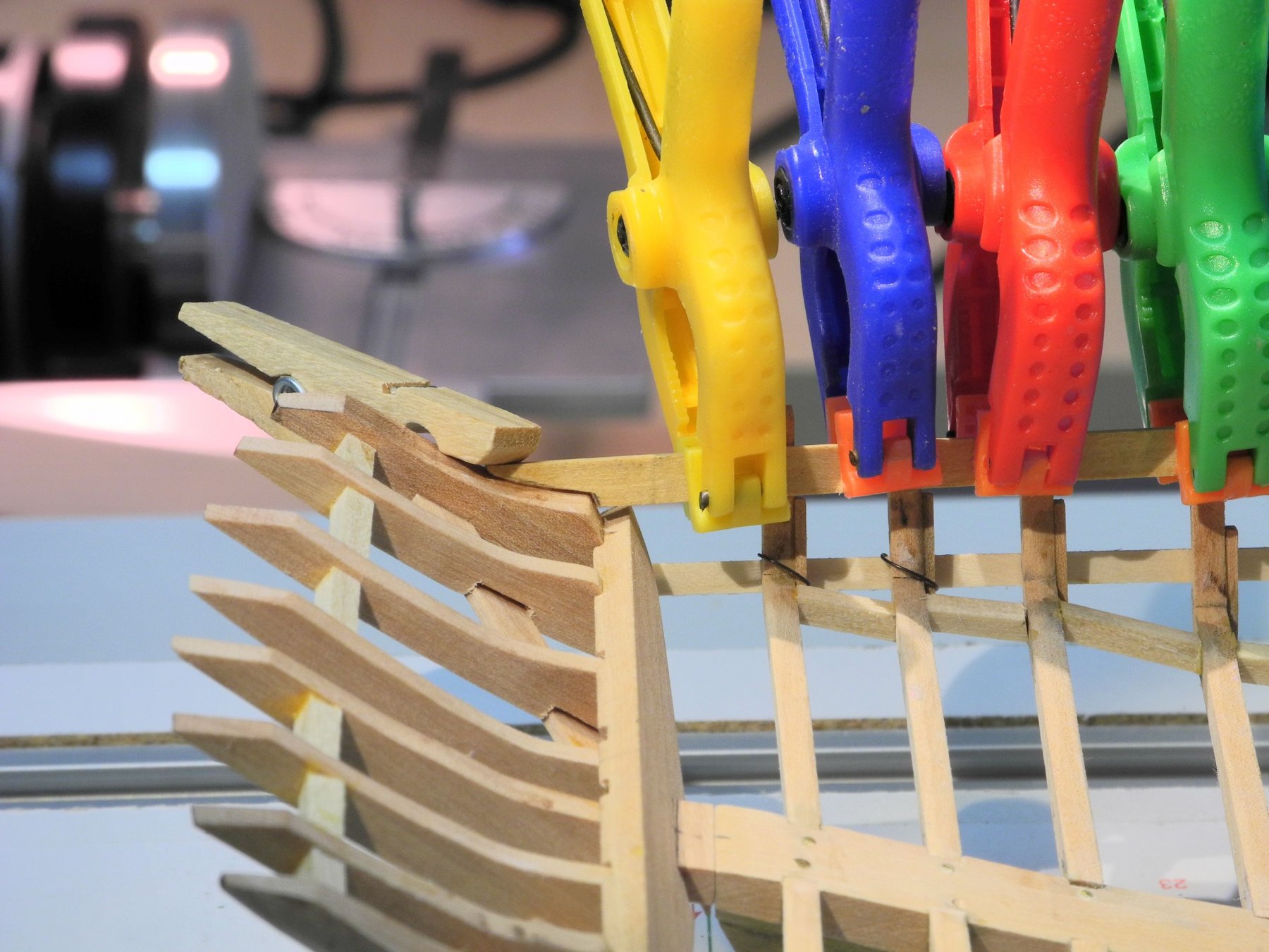
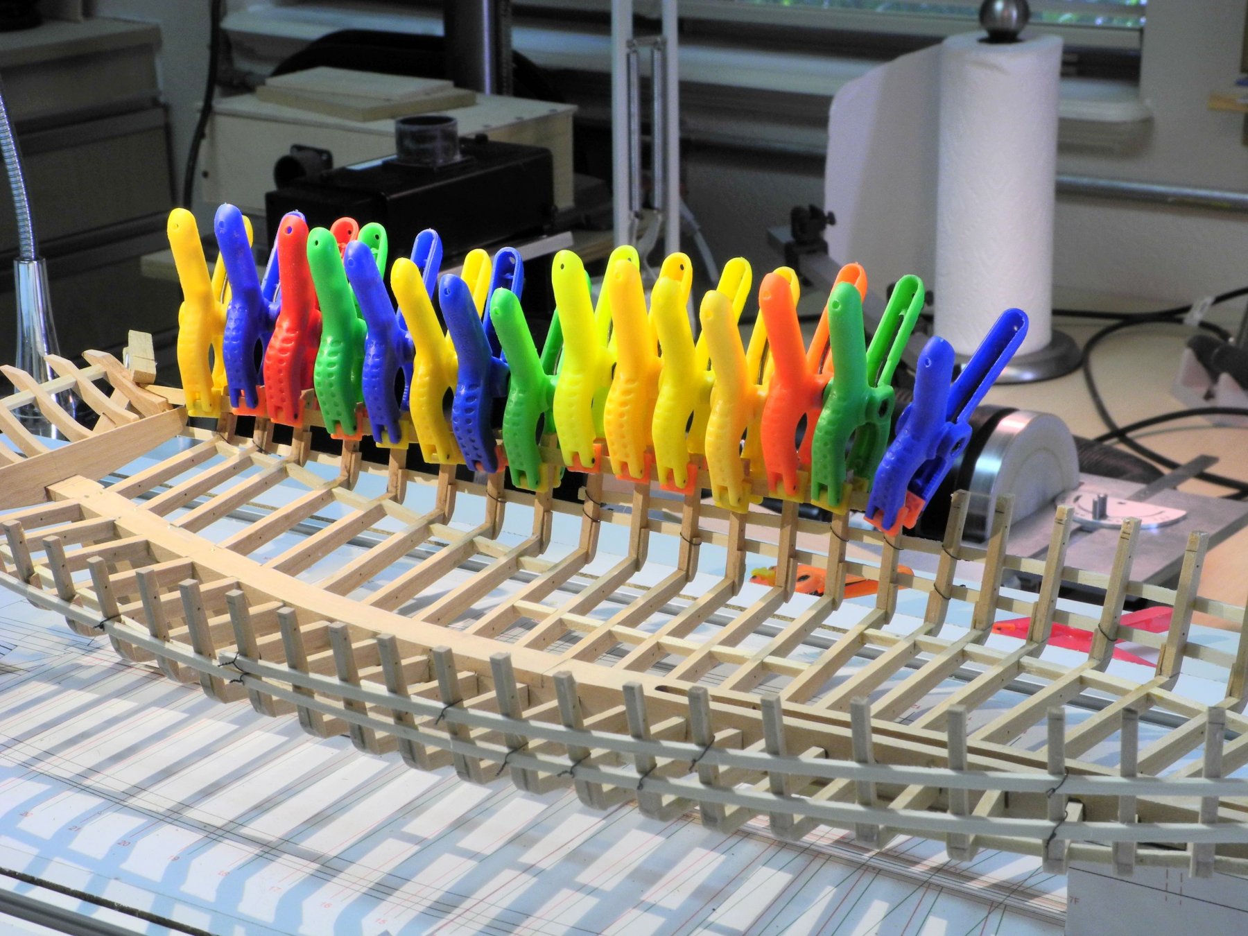
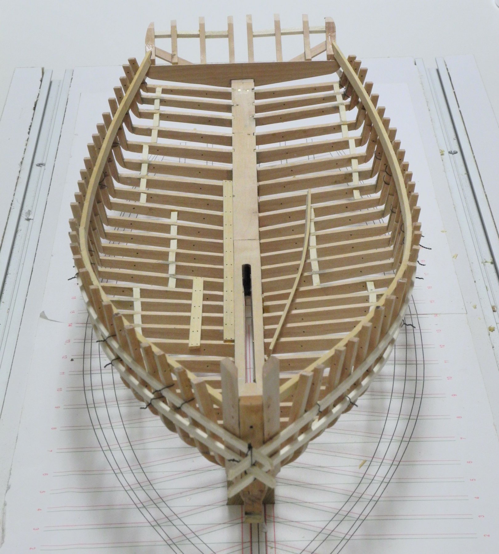
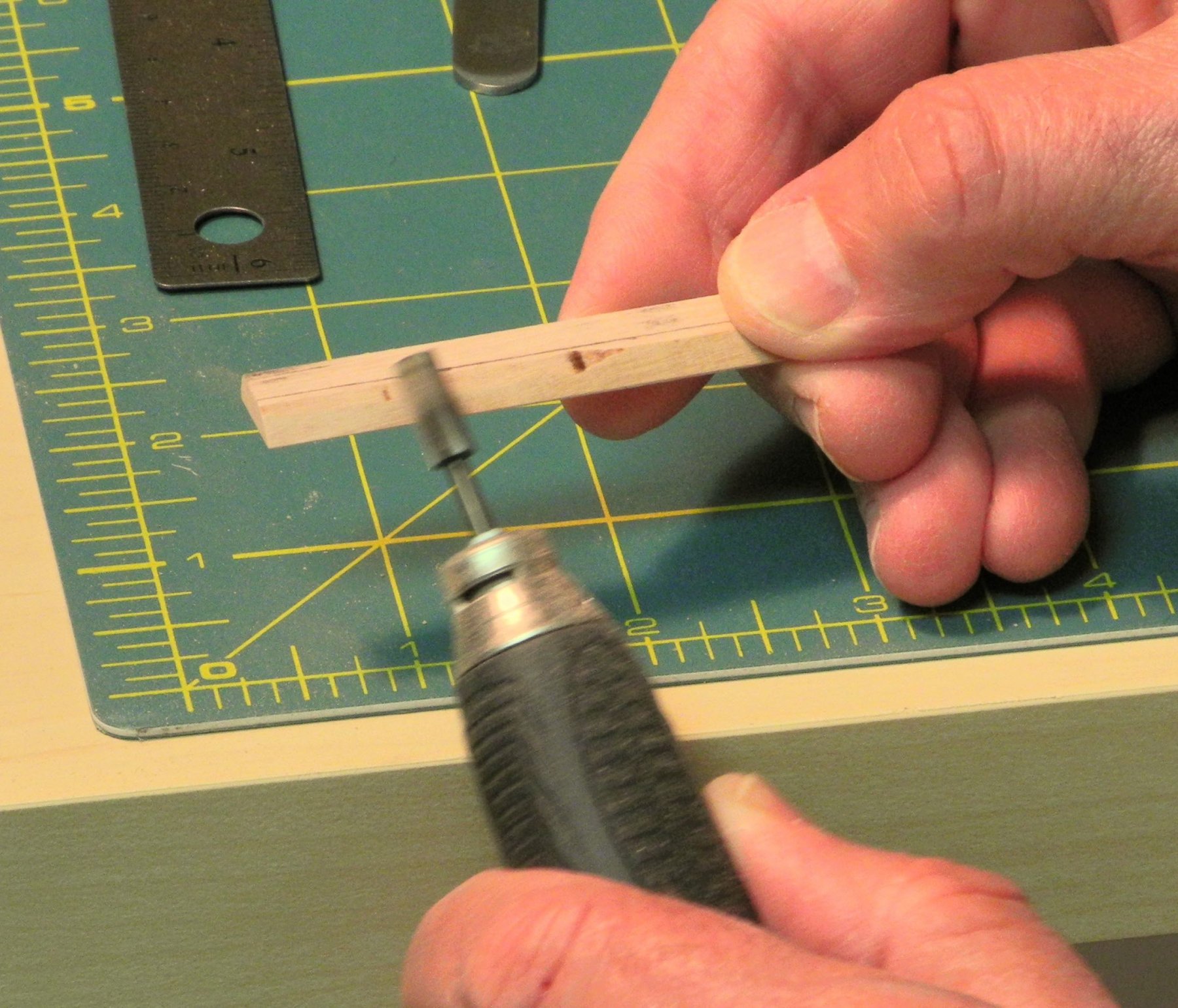
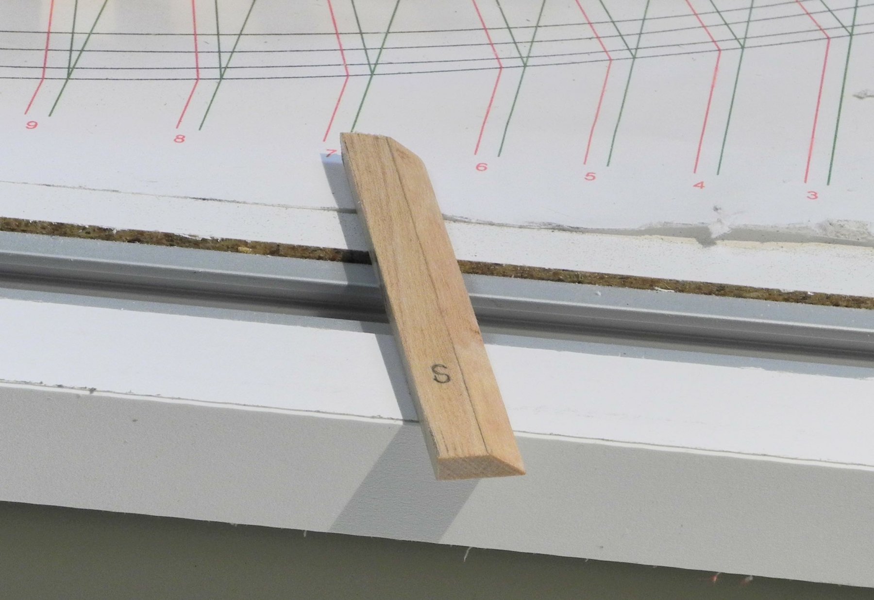
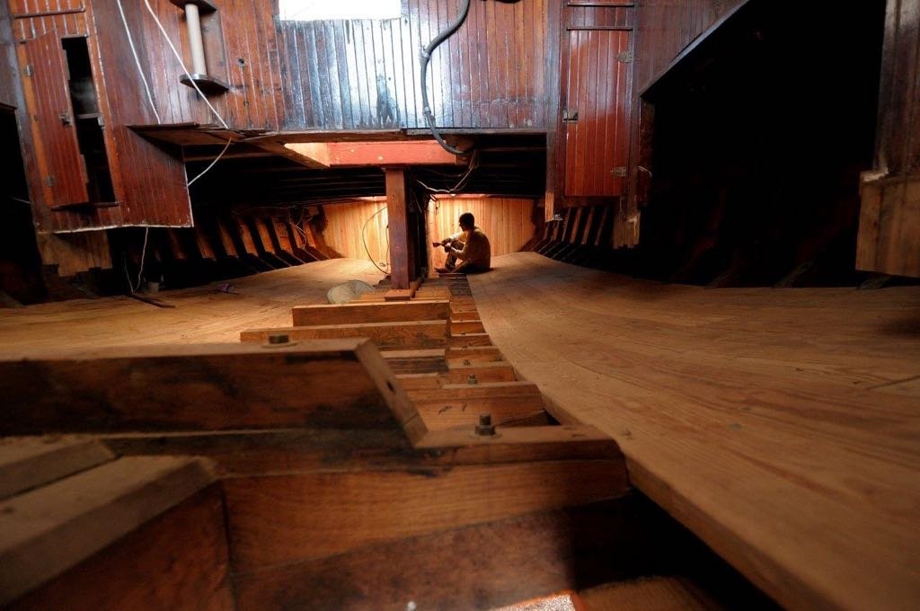
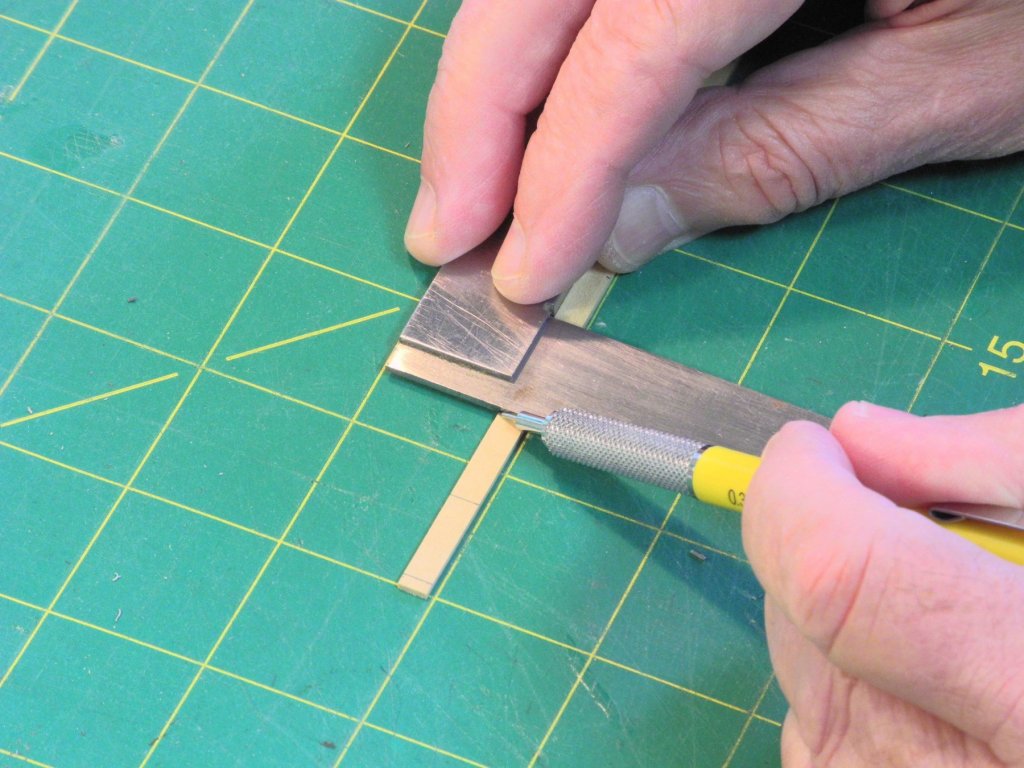
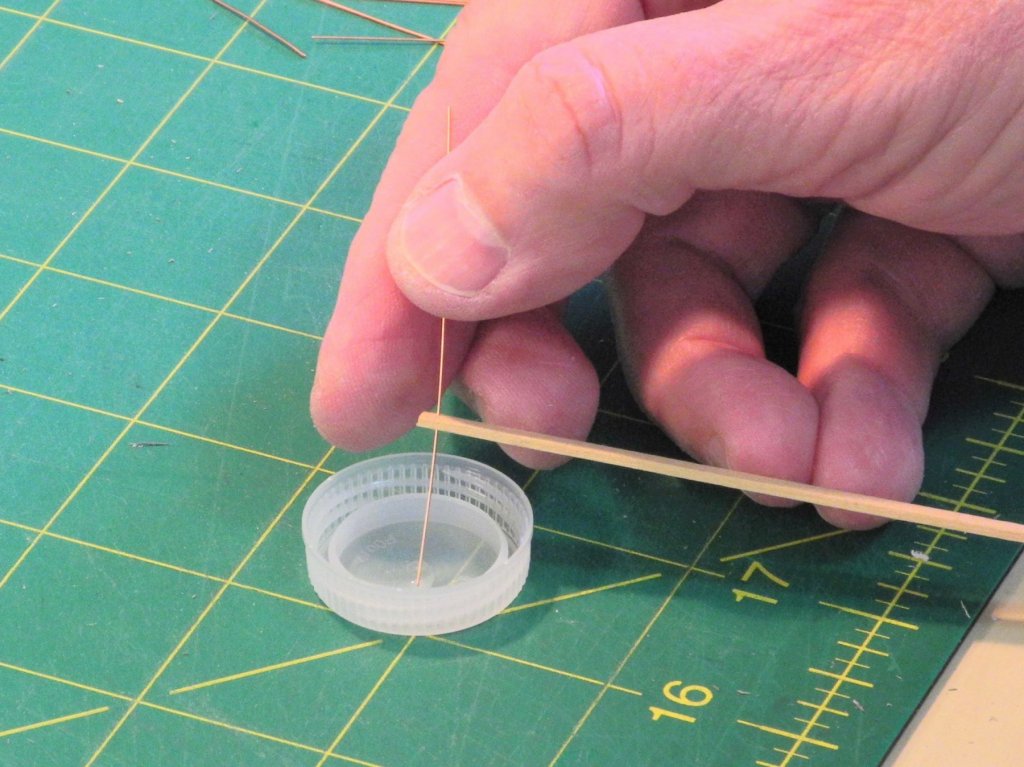
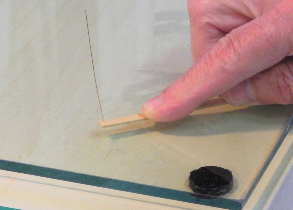
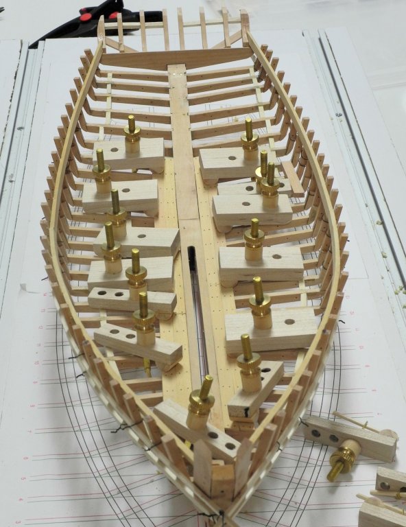
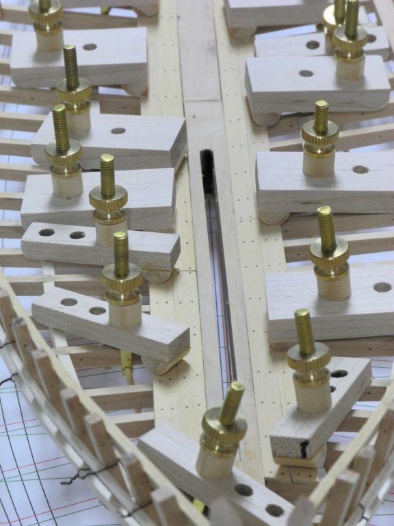
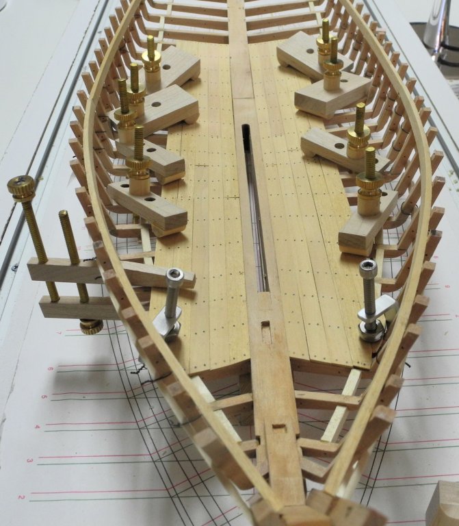
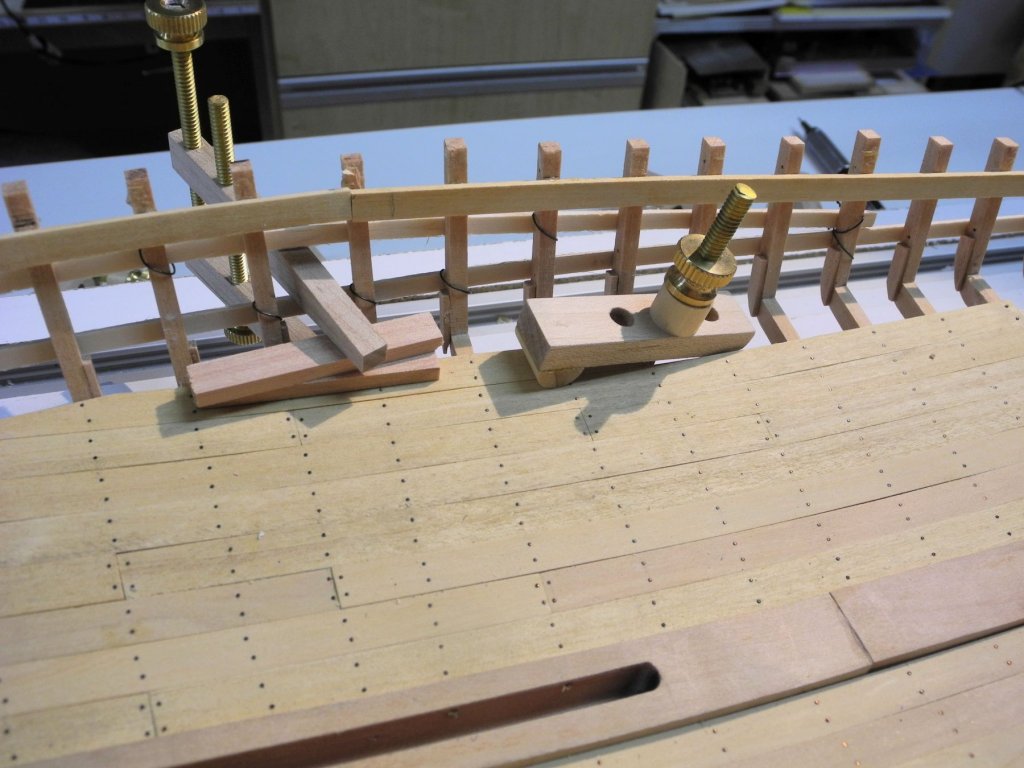
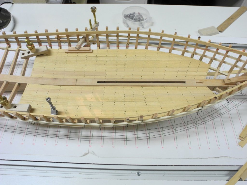
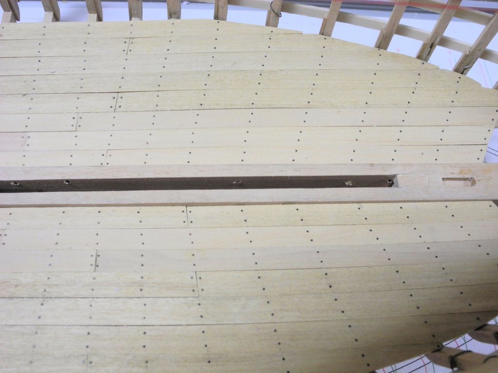
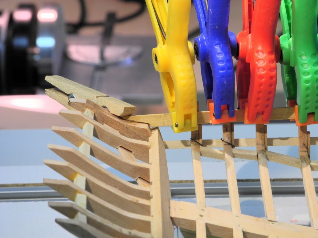
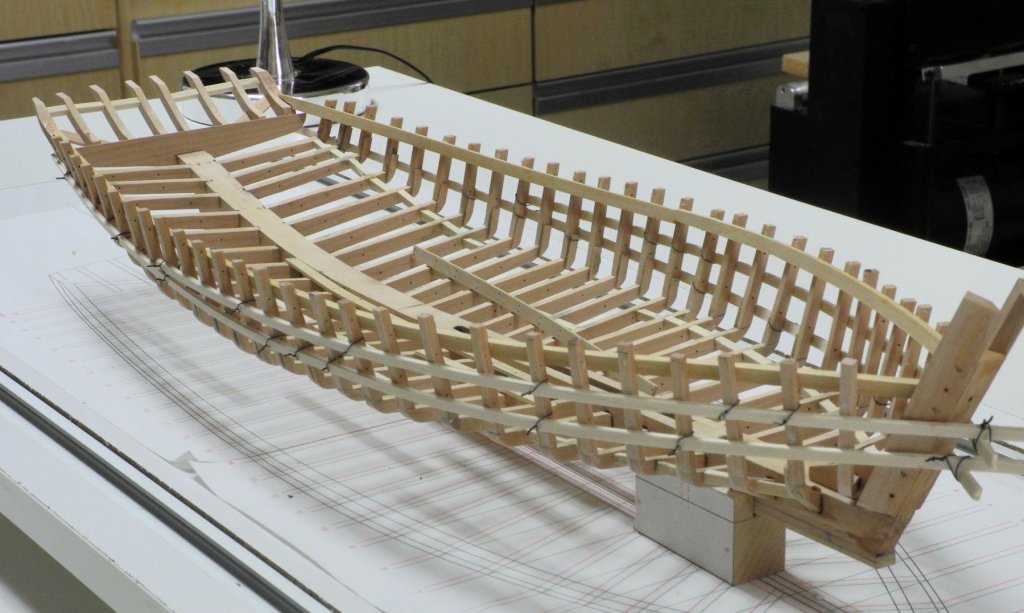
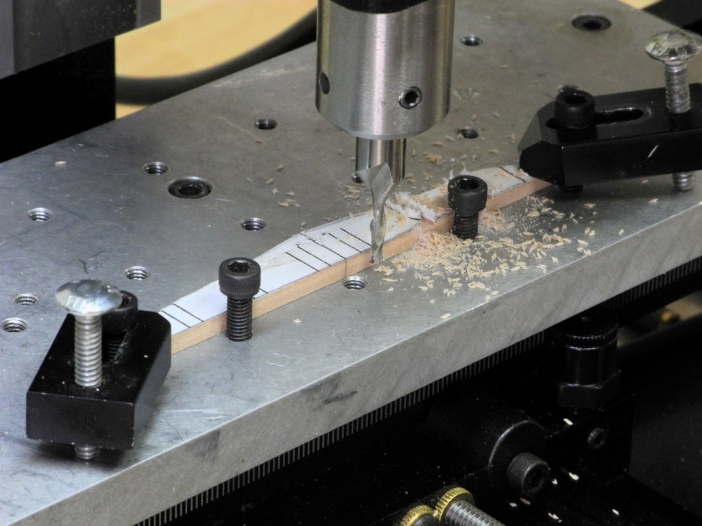
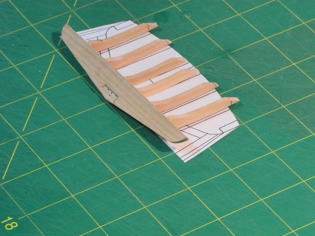
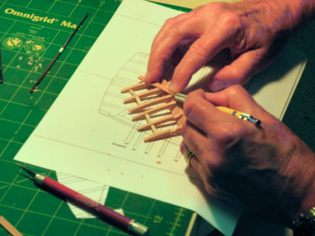
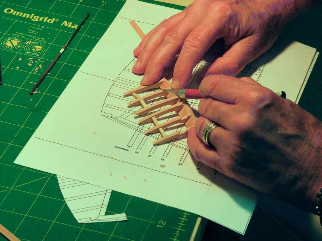
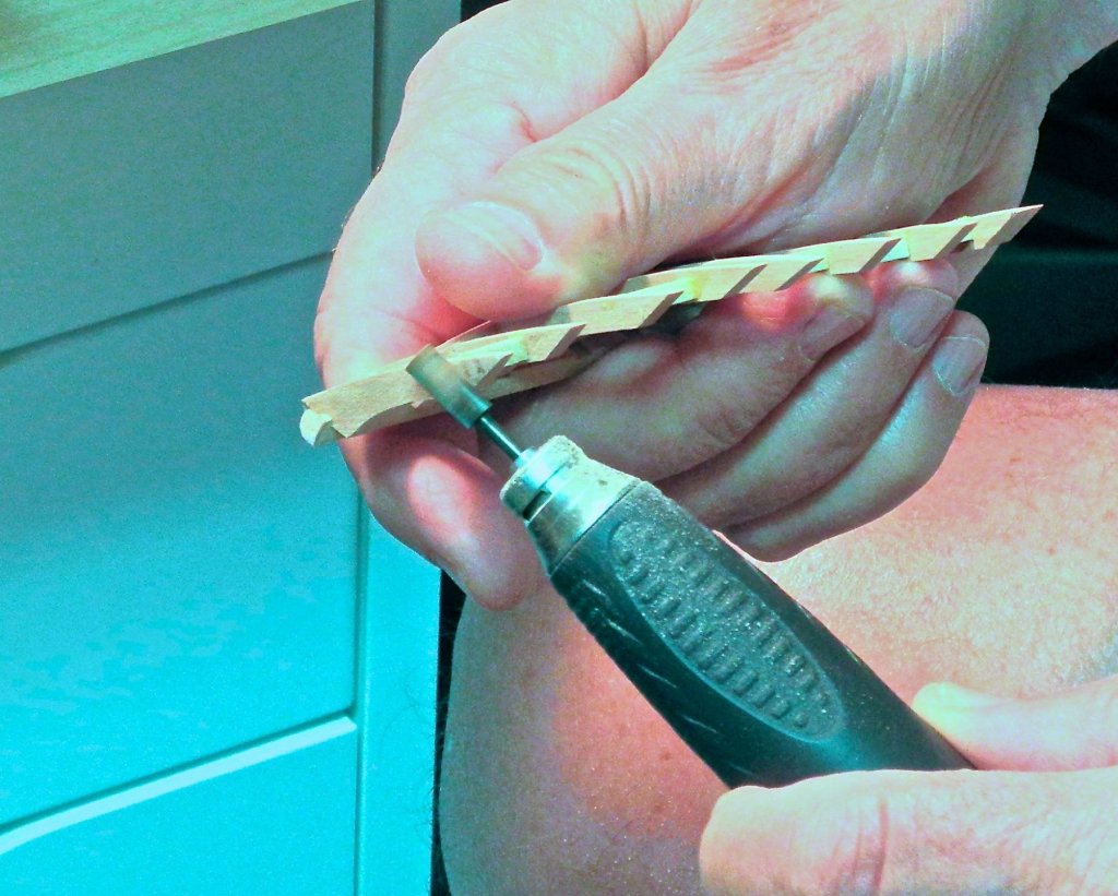
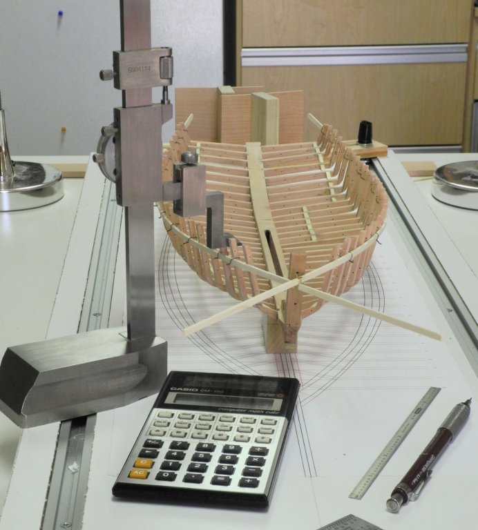
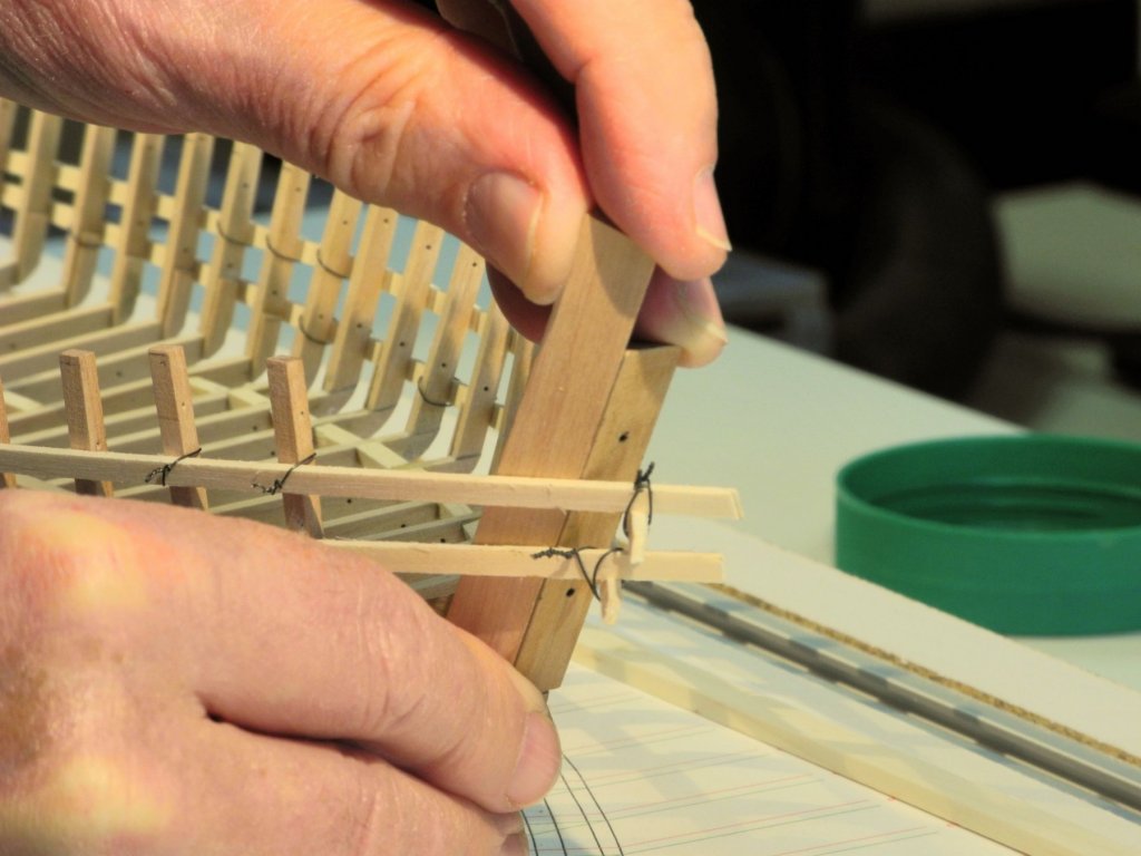
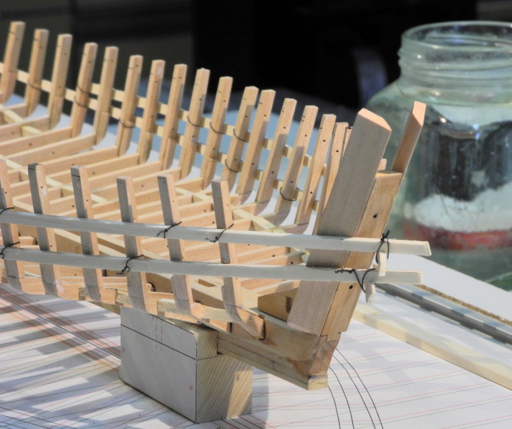
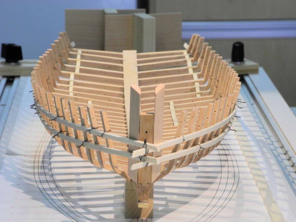
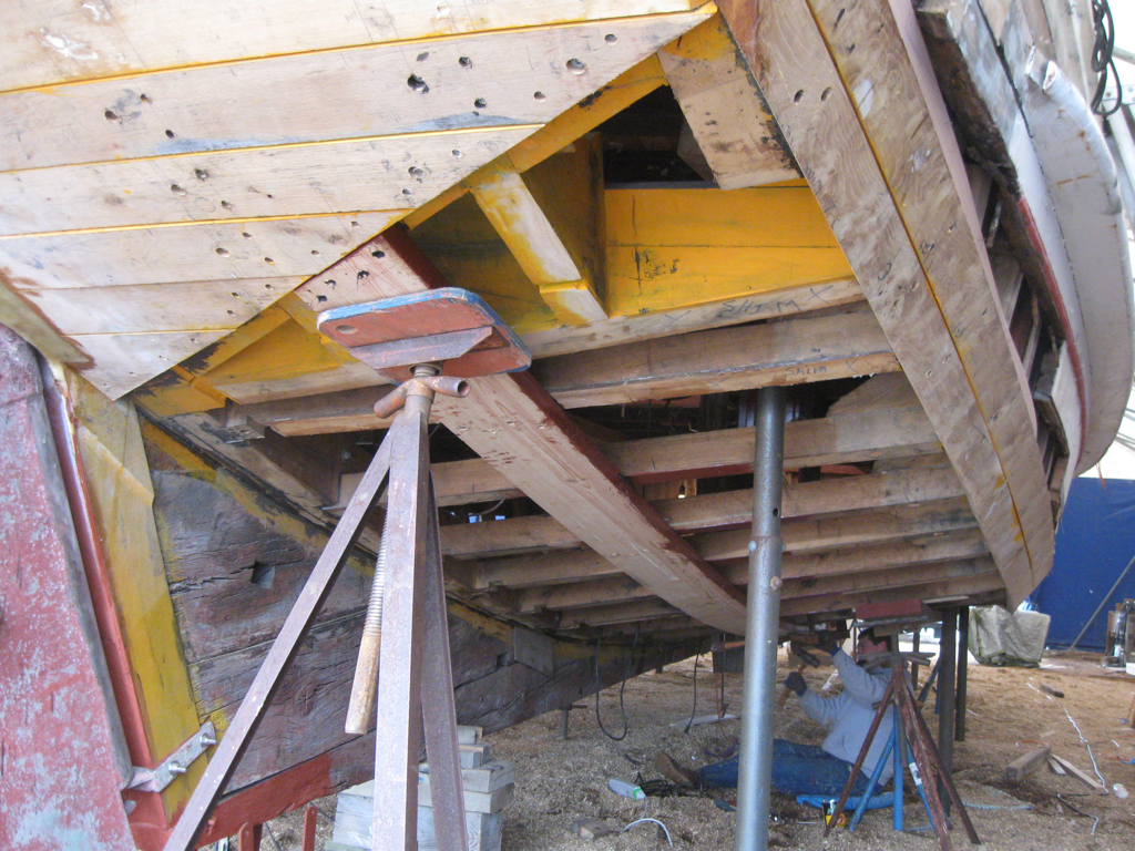
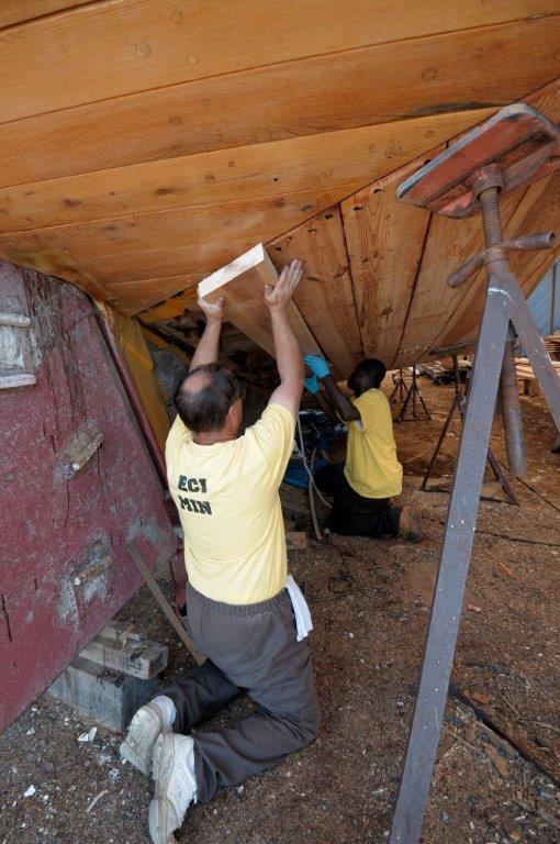
Part 15 – Ceiling Planks Hi Everyone. Again, it has been a while since my last post. At the end of April my wife went into hospital for some surgery, and we were expecting her to be home in a couple of days. Unfortunately there were some serious complications that kept her hospitalized for about 10 days, followed by some convalescing at home. Needless to say modeling activities were put aside during that time. Fortunately she’s doing well and is getting back to feeling normal. So, back to work on Kathryn. The ceiling planks are next on the plate. There’s a lot of interior detail to be worked on, and the ceiling planks need to be completed before any of the other details can be tackled. According to the HAER documentation, ceiling planking runs from the third frame back to frame 20. This is the area used for some below-deck storage and for forward berthing. There’s a bulkhead that forms the forward wall of the cabin at frame 20, and the depth of the hull from frame 20 aft is very shallow, so it doesn’t make sense to install ceiling planks aft of frame 20. However, the photos from the recent reconstruction appear to show ceiling being laid under the cabin. This photo was taken looking forward – the vertical paneling is actually the forward wall of the cabin, and the bulkhead at the forward end of the cabin has not yet been installed. Since this model is intended to depict Kathryn as she was originally built, the ceiling planks will end at frame 20. Kathryn’s ceiling planks are approximately 9” wide x 1-3/4” thick. Since the plan is for some of the ceiling to be visible, simulated bolts will be installed on the planks. The process for installing these bolts is the same as used in my Dunbrody build. First, the location of the bolts will be marked on a plank corresponding to the middle of the frame below the plank, except where planks meet in the middle of a frame. A small square is then used to draw a perpendicular line across the plank. (Where the plank was being installed on a cant frame, a line matching the angle of the frame was drawn instead.) The Sensitive Drilling Attachment on the milling machine is used to drill the bolt holes. This drilling setup allows for the holes to be drilled a consistent distance from both edges of the plank. The plank is pressed against the wood strip, all the holes are drilled, the plank is reversed, and the holes for the other side are drilled. After drilling, the pencil lines are all erased with an artist’s eraser. The bolts are 24 gauge copper wire that has been work hardened and then cut into short ‘rods’. The holes in the plank have been drilled using a #76 drill. The rod is fed through the hole and then dipped into a puddle of medium viscosity CA glue. By feeding the rod through the hole before applying glue, any CA smear is on the bottom of the plank and won’t detract from the finished look of the plank. The plank is then gently pushed down to the surface of a plate glass sheet – this causes the bolt to be set right against the bottom of the plank, so little or no trimming or sanding is needed on the bottom of the plank. After all of the rods have been glued to the plank, the rods are then clipped off on the top side of the plank and filed or sanded smooth – ready for blackening. Since the bolts are copper rods, Liver of Sulfur is used for blackening. The following photo shows a plank that is still wet from blackening. I have found that the blackening agent slightly discolors the wood, so a clear water wash is scrubbed onto the entire plank while it is still wet from the LOS solution. Planking clamps as used by EdT were used to clamp the ceiling planks in place. My existing supply of planking clamps consisted of clamps that were narrow enough to fit between the frames, so I made a few wider clamps for Kathryn. A combination of the old and new clamping planks was used for the ceiling planking. In some cases I needed to use different types of clamps. In the following photo a screw clamp is being used on the starboard side, and home-made miniature c-clamps are used for the forward ends of the planks. In other cases the temporary ribbands interfered with the screw clamps, so some scrap wood was used to elevate the arm of the clamp. When the outermost plank was installed an arrangement of the miniature c-clamps was used. Since frames 3 through 11 are cant frames, the bolting pattern reflects these frames, and I thought it made for a pleasing effect. The next step is the installation of the ceiling planks along Kathryn’s sides. Thanks everyone!


- 878 replies
-
- 28
-

-
Thanks Patrick. Unfortunately Kathryn is coming along much slower than I had planned - other priorities keep showing up. Thanks Jack - glad you like it.
-
Thanks Druxey. I always seem to be learning something new from your posts - in all my years of bird carving and learning about birds, I never heard the name 'budgerigars' used for parakeets!
-
It's great to see you making progress again, Brian!
-
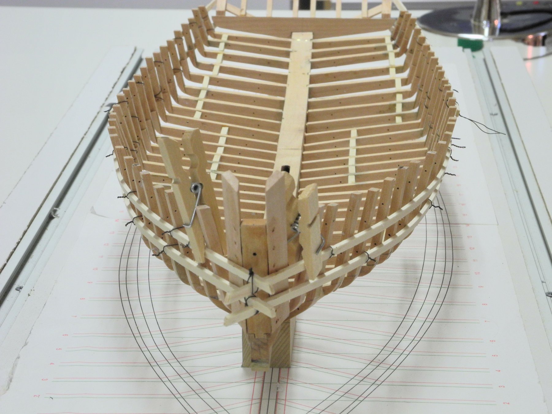
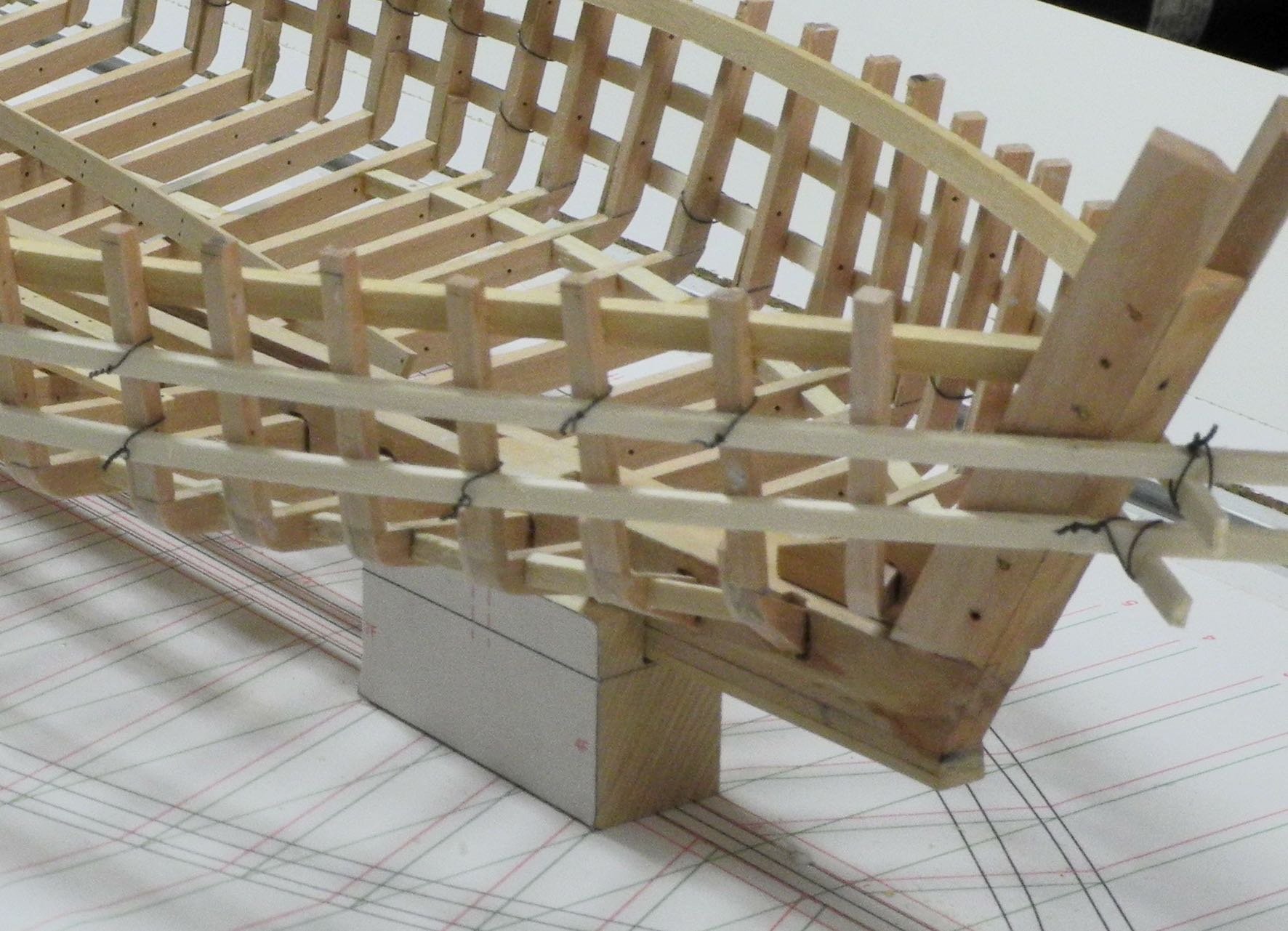
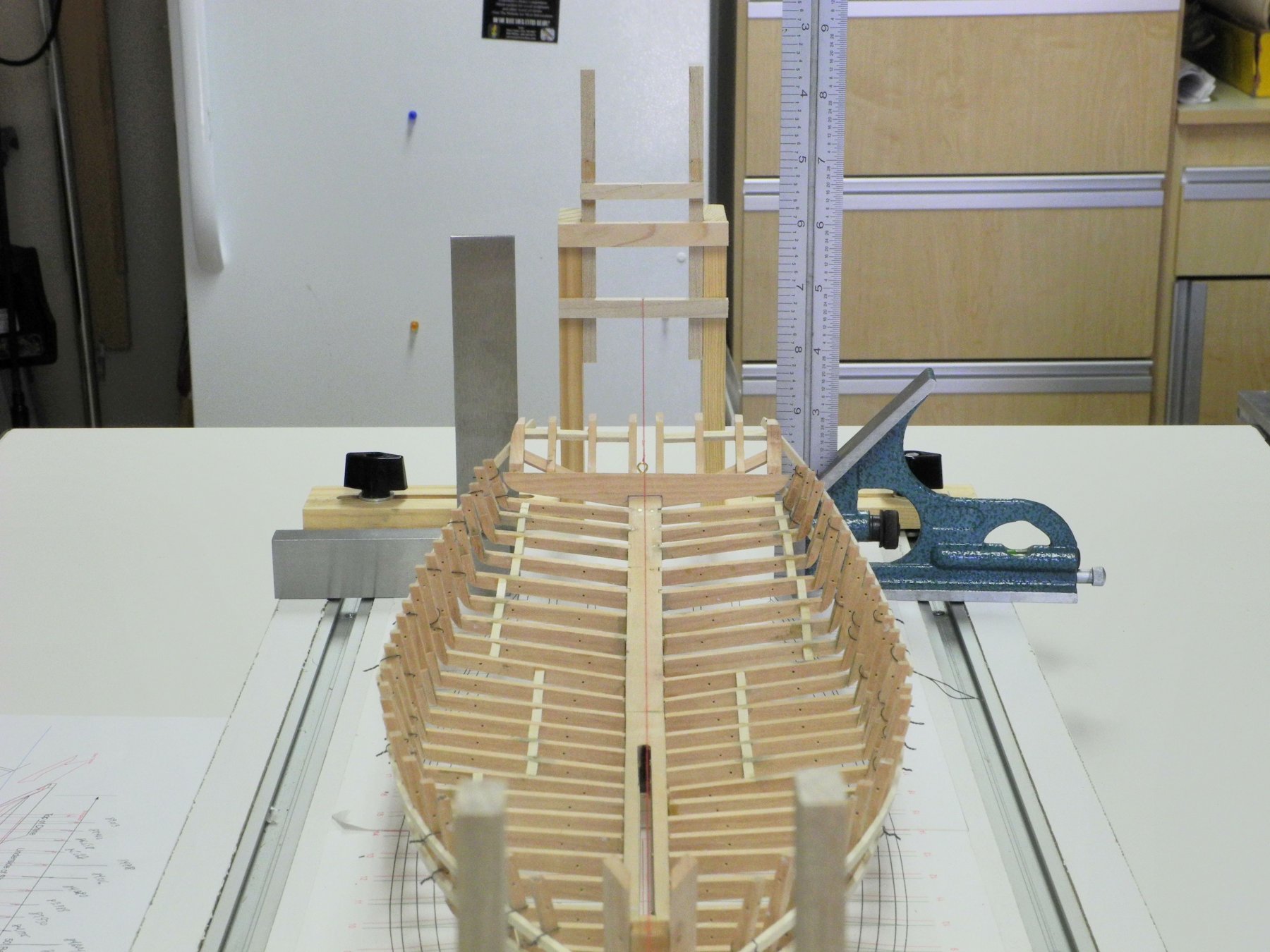
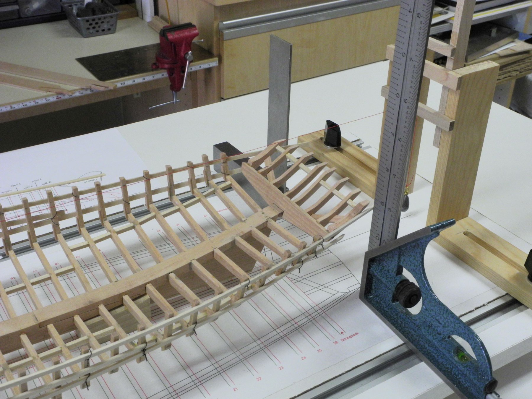
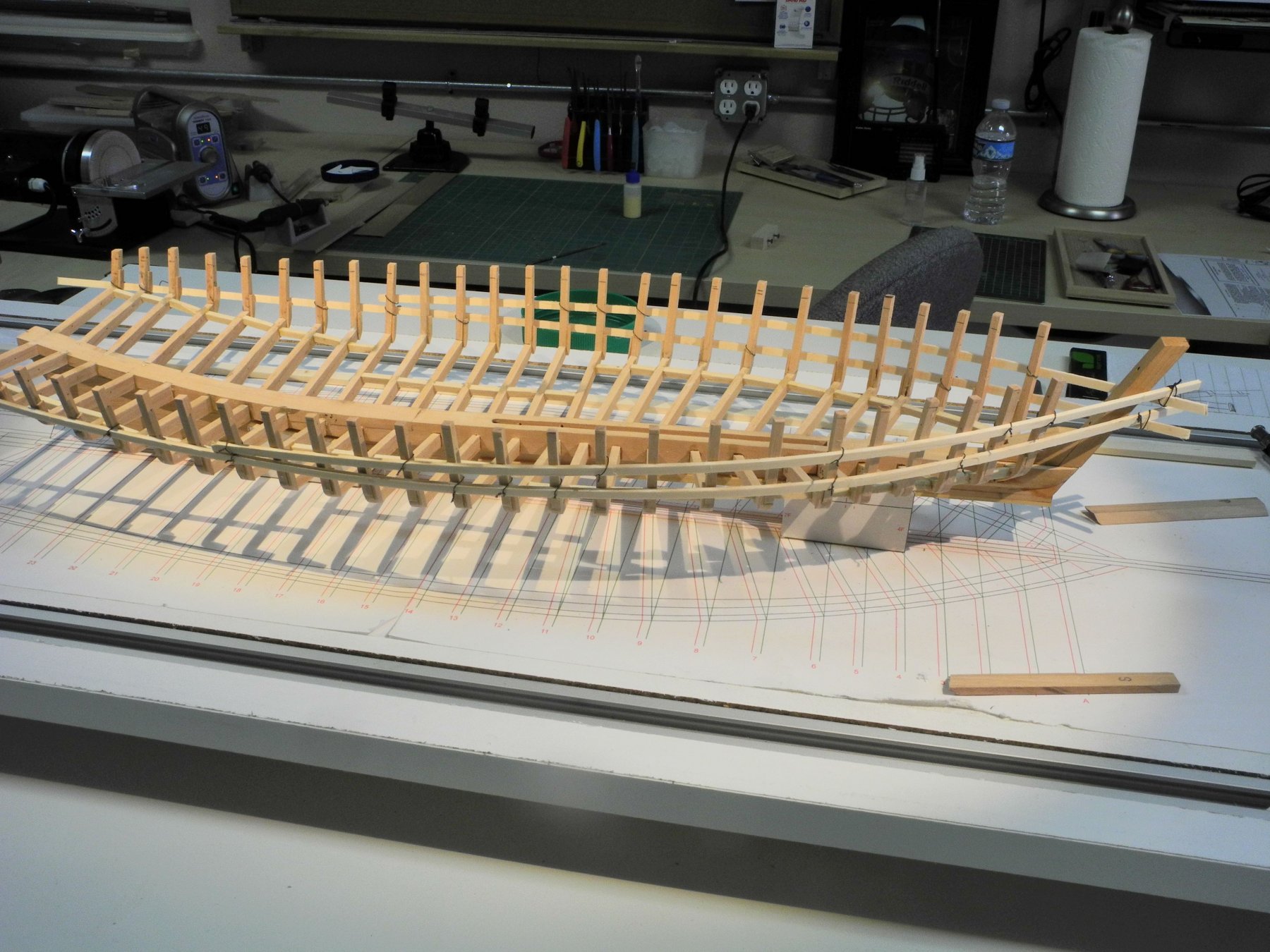
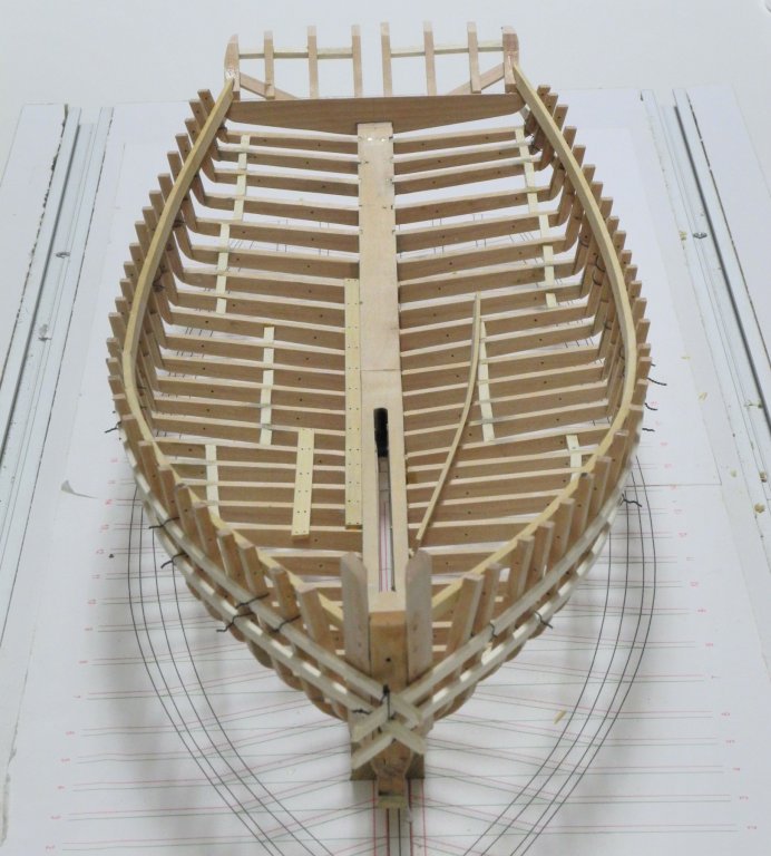
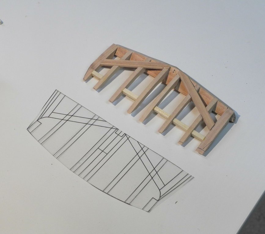
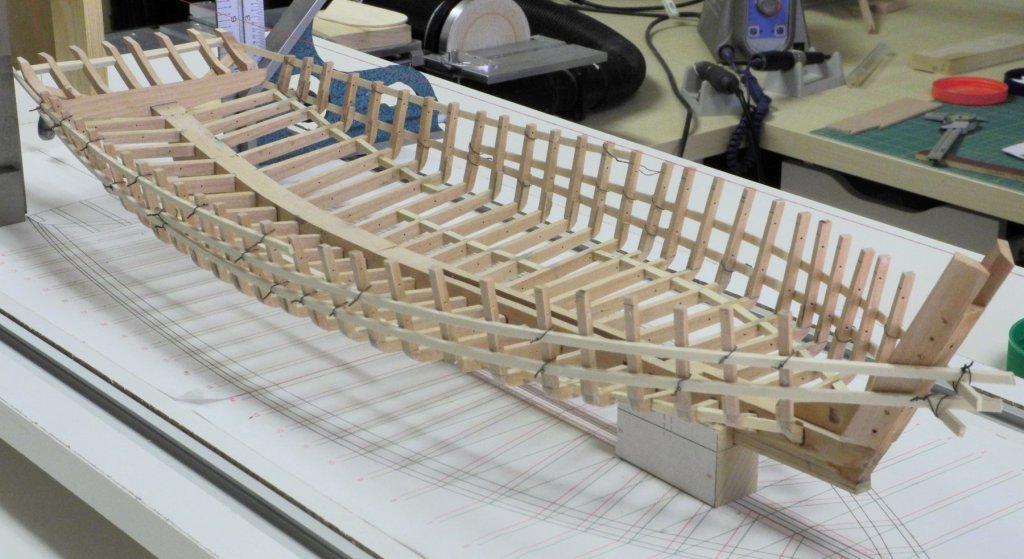
Part 14 – Deck Clamp Ok, so 2 updates in the same day - this will bring us to the current state of the build. Kathryn’s deck clamp runs the entire length of the ship, and is made from pine. A reinforcing piece made of oak is installed over the forward part of the clamp. The main clamp was cut into two pieces, joined at frame 12. This will allow the reinforcing piece to sit over the joint when it’s installed later in the build. Before installing the clamp, it was necessary to install the forward-most frame, which is let into the stem knee rather than the keelson. This frame will provide additional support to the planks in the bow area. The deck clamp can provide some needed structural support to the stern assembly if it is attached to the outermost stern timbers. A notch was cut into the end of the deck clamp to match the shape of those stern timbers, and the clamp was then glued to the stern timber as part of the installation. Since the deck clamp will keep the frames aligned until the ceiling and outer planks are installed, it was necessary to glue and clamp the deck clamp to every one of the hull’s frames. This made for a very tight setup. The finished deck clamps have provided good overall strength to the frames and the stern pieces, and the final shape of the hull can now be seen. As can be seen in these last two photos, some of the ceiling planks have been started. This will be the topic for the next post. Thanks everyone!


- 878 replies
-
- 23
-
-
I love the last photo in the sequence - the full ship in a giant's big hand. It shows how much amazing detail you're able to fit into such a tiny space, and is one of those "OMG" shots.
-
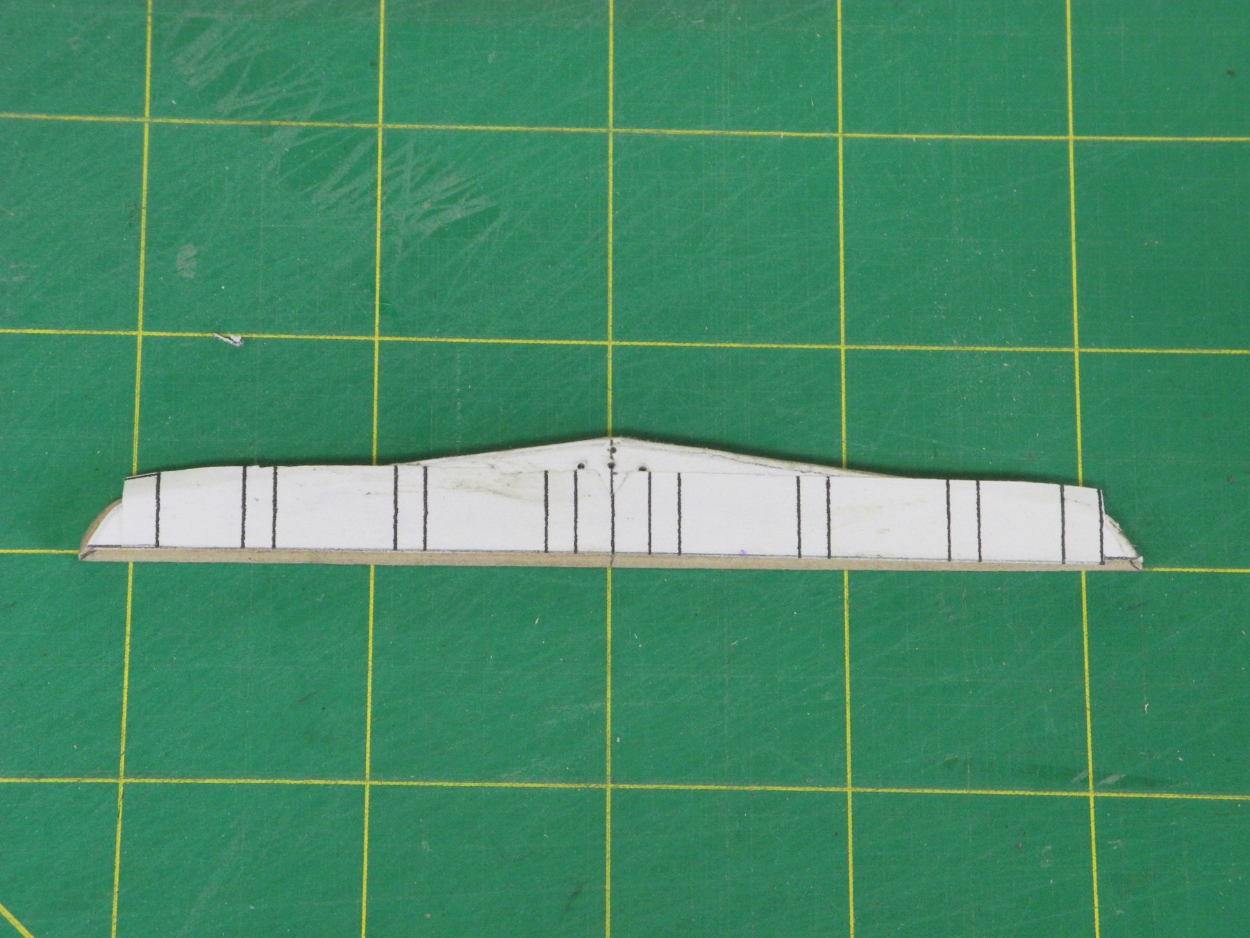
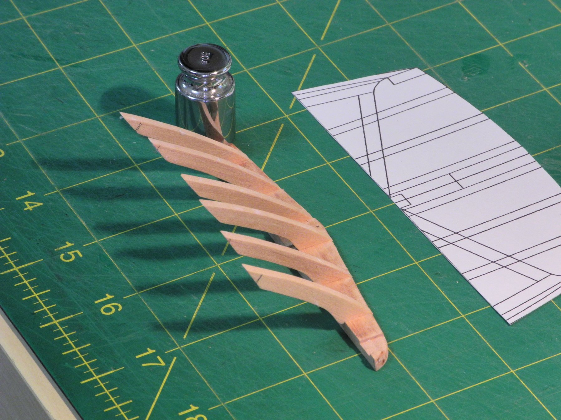
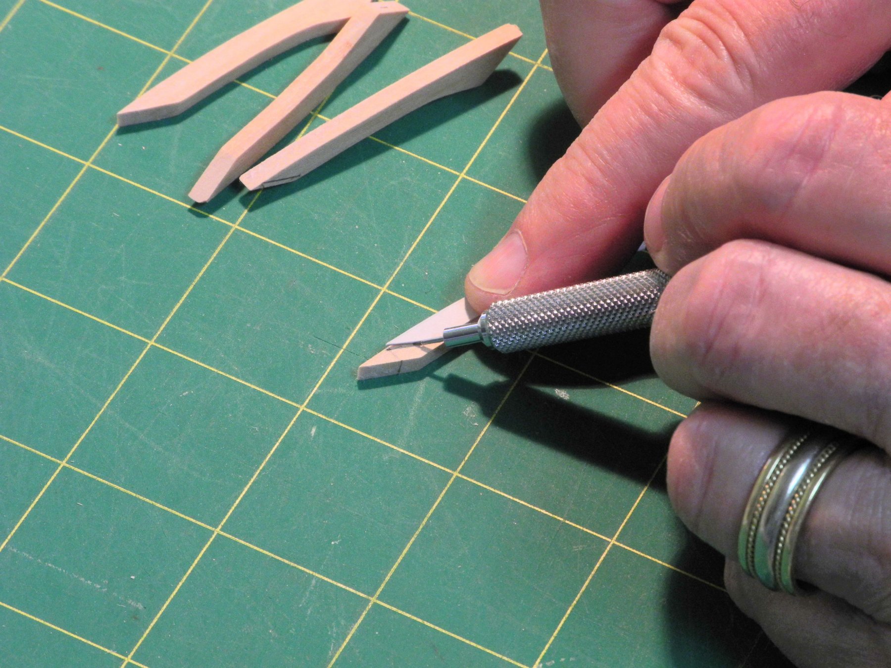
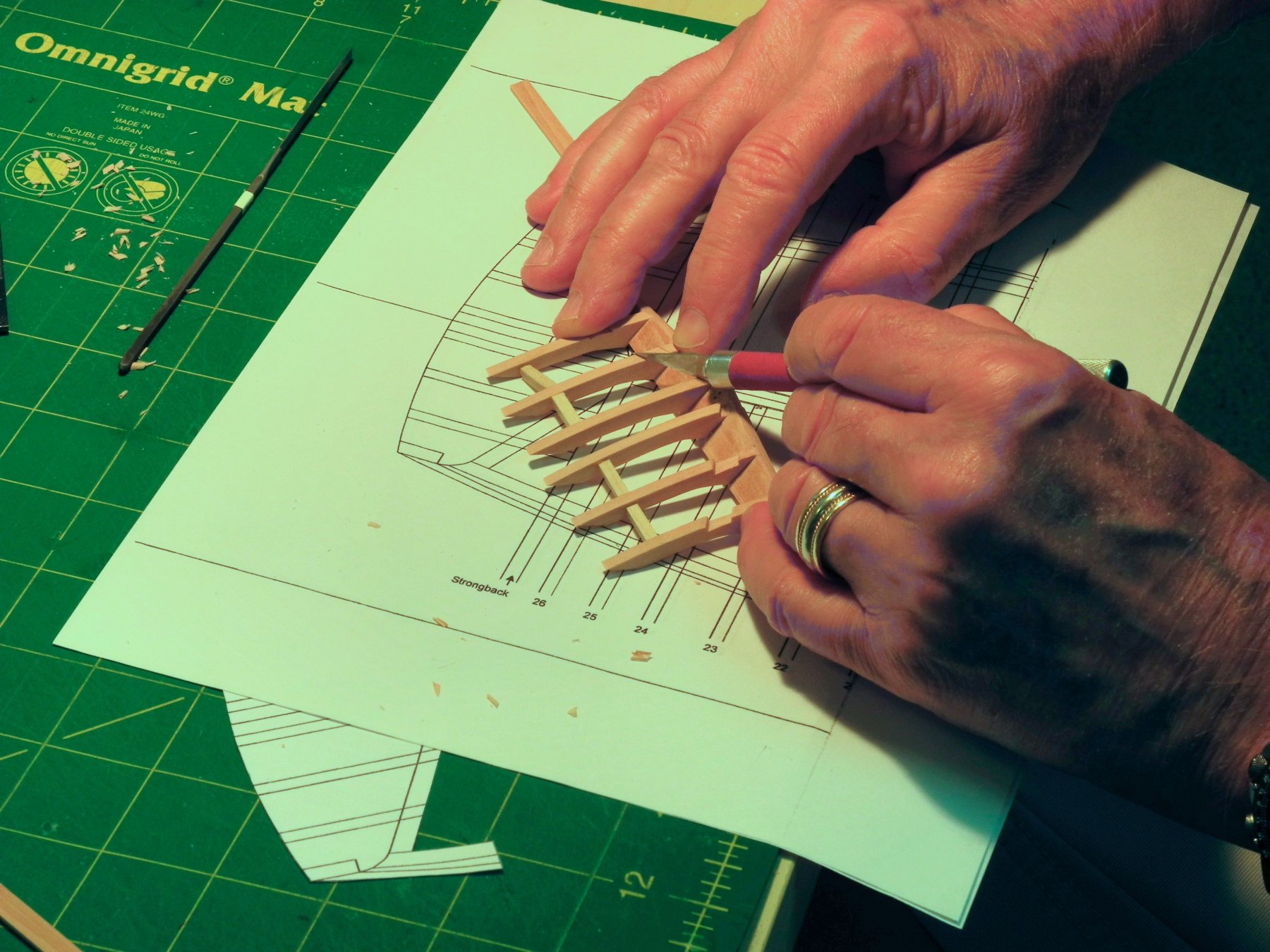
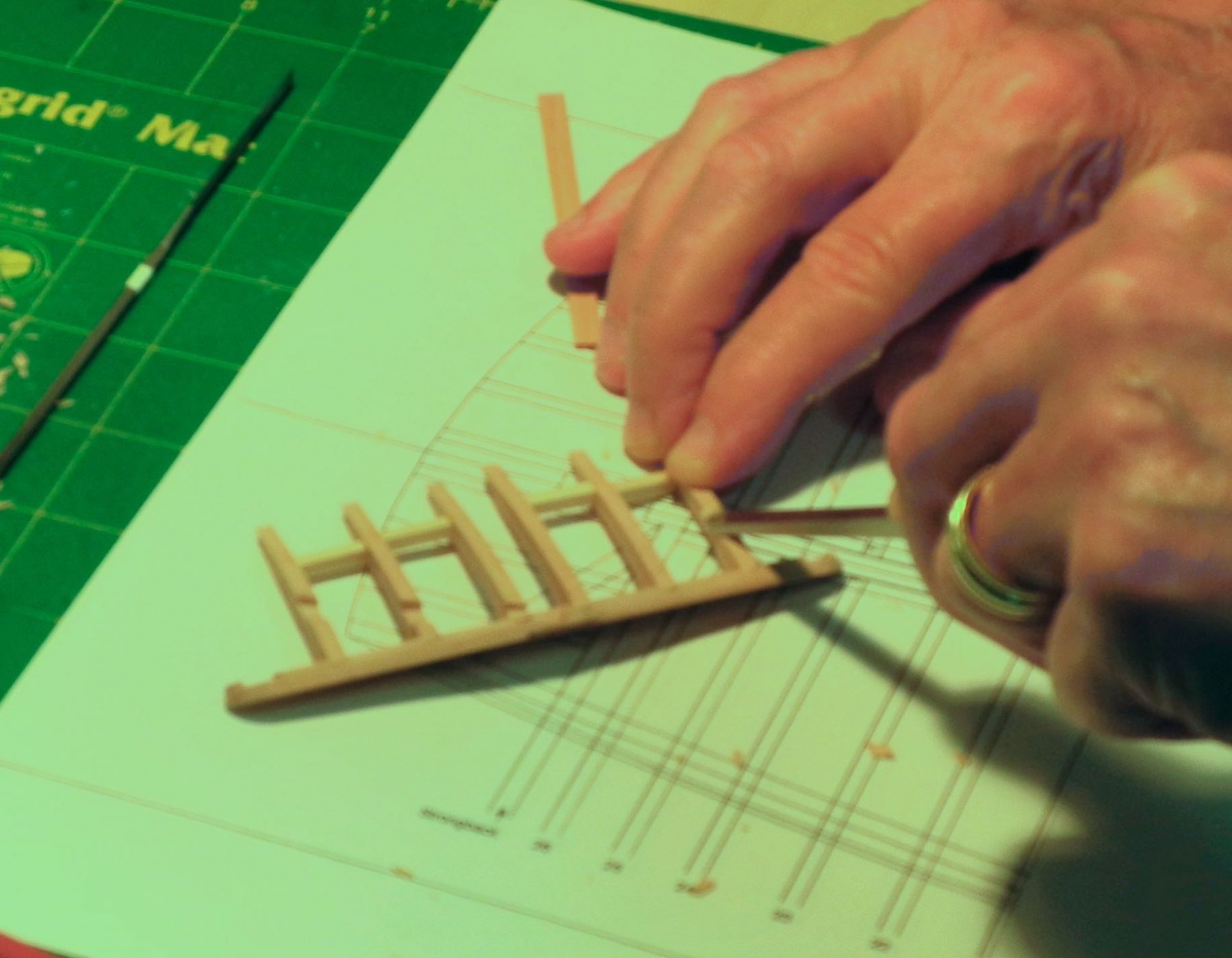
Part 13 – Stern Timbers Well, I finally found the time (and the courage) to work on the stern timbers. After several attempts at drafting the timbers, I decided to use a simpler approach. I would use the profile of the middle timber as a guide, and would alter the length of the various timbers as I assembled the stern. The first step was to correct an error I had made in cutting the end of the keelson, which I had left perpendicular. The strongback is mounted against the keelson end, and sits at the same angle as the end of the keel. A small wedge was made and installed to give the keelson the appropriate angle. The drawings of the stern timbers and the strongback were glued to the appropriate stock and then cut out on the scroll saw. A mounting slot was cut into the forward edge of the strongback to provide a more secure mounting position when joined to the end of the keelson. A drawing of the timber arrangement was then glued to the strongback. This drawing showed the positions of each of the stern timbers. Slots for each of the stern timbers were then milled in the strongback. These slots were tight enough to allow the temporary positioning of each of the stern timbers. In the following photo these timbers are held in place by friction, with no gluing involved. The length of each timber was then determined by matching this configuration against the drawing of the stern timbers. The profile drawing of the stern timbers was then used to ensure that cutting down the length of the stern timber resulted in the correct angle for the end of the timber. The stern assembly was then glued together, using small braces to ensure the correct parallel alignment of the stern timbers. This assembly was then marked for the diagonal braces that were to be installed. Since these braces are let into the stern timbers and sit flush against the edge of those timbers, stop cuts were made in each timber to guide subsequent cutting. The slots were cut down to the final depth using a small chisel and a hobby knife. (Apologies for the out-of-focus photos) The outer timbers were made of thicker stock than the interior timbers since they need to be shaped to allow hull planking to properly lie against them. The initial shape was determined by laying a transparent template over them. This transparent template was made by printing the drawing on transparency paper, and allowed proper alignment by showing the individual timbers. The outside edge of the end timbers was roughly shaped using a fine stump cutter. Final shaping, or fairing, will be done when the planking is laid. The following photo shows the partially finished stern assembly with the transparent template. Clamping the stern assembly to the keelson for gluing proved difficult, so two temporary ribbands were used to provide support. These ribbands were held in the proper position at the stern by aligning two heavy squares with the outer edge of the drawing on the construction board. This forced the ribbands to the correct shape and provided a relatively solid way to hold the stern assembly in place during the gluing process. (I was later informed that the skipjack builders would often use scaffolding to hold assemblies in place during the building - similar to my use of these ribbands) The stern timbers are permanently in place, but are rather fragile. They can be further secured by the installation of the deck clamps, which will be the topic of the next post.


- 878 replies
-
- 18
-
-
Argus is shaping up nicely, Rich. Time and patience is really paying off in your planking.
- 1,135 replies
-
- 3
-
-
- model shipways
- syren
- (and 2 more)
-
Thanks, Kees. I'm very happy with my shop and tools - and for my very understanding wife! I visited your 'museum' and enjoyed it very much.
-
Thanks, Patrick. Lots of work still ahead. Thanks, Albert. Thanks, Popeye. To me, the knightheads are real important for the planking to sit correctly.
-
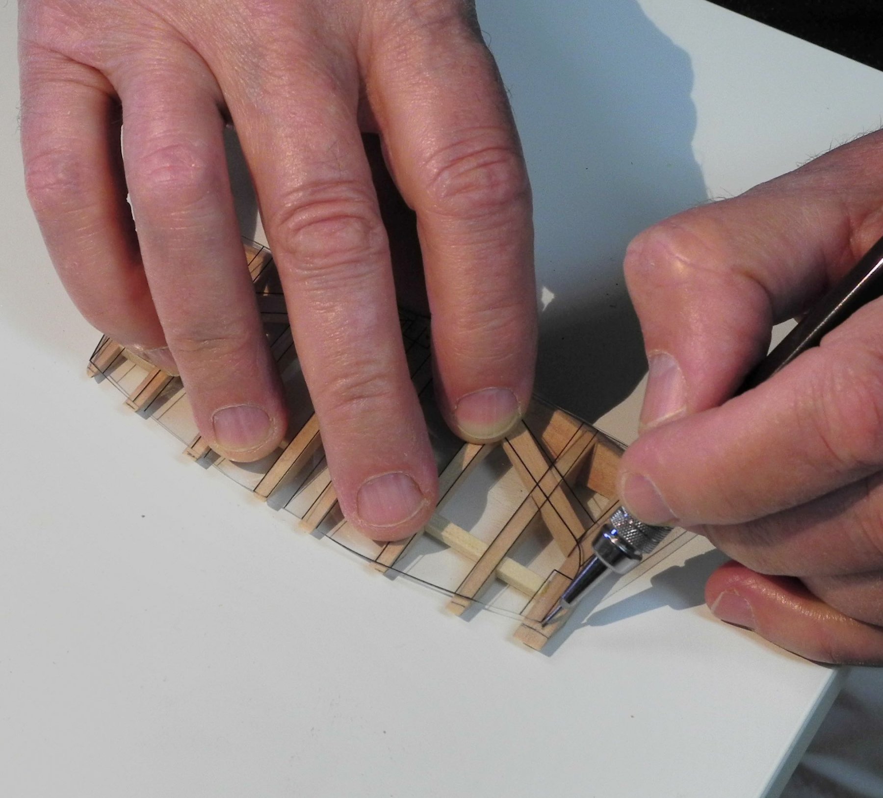
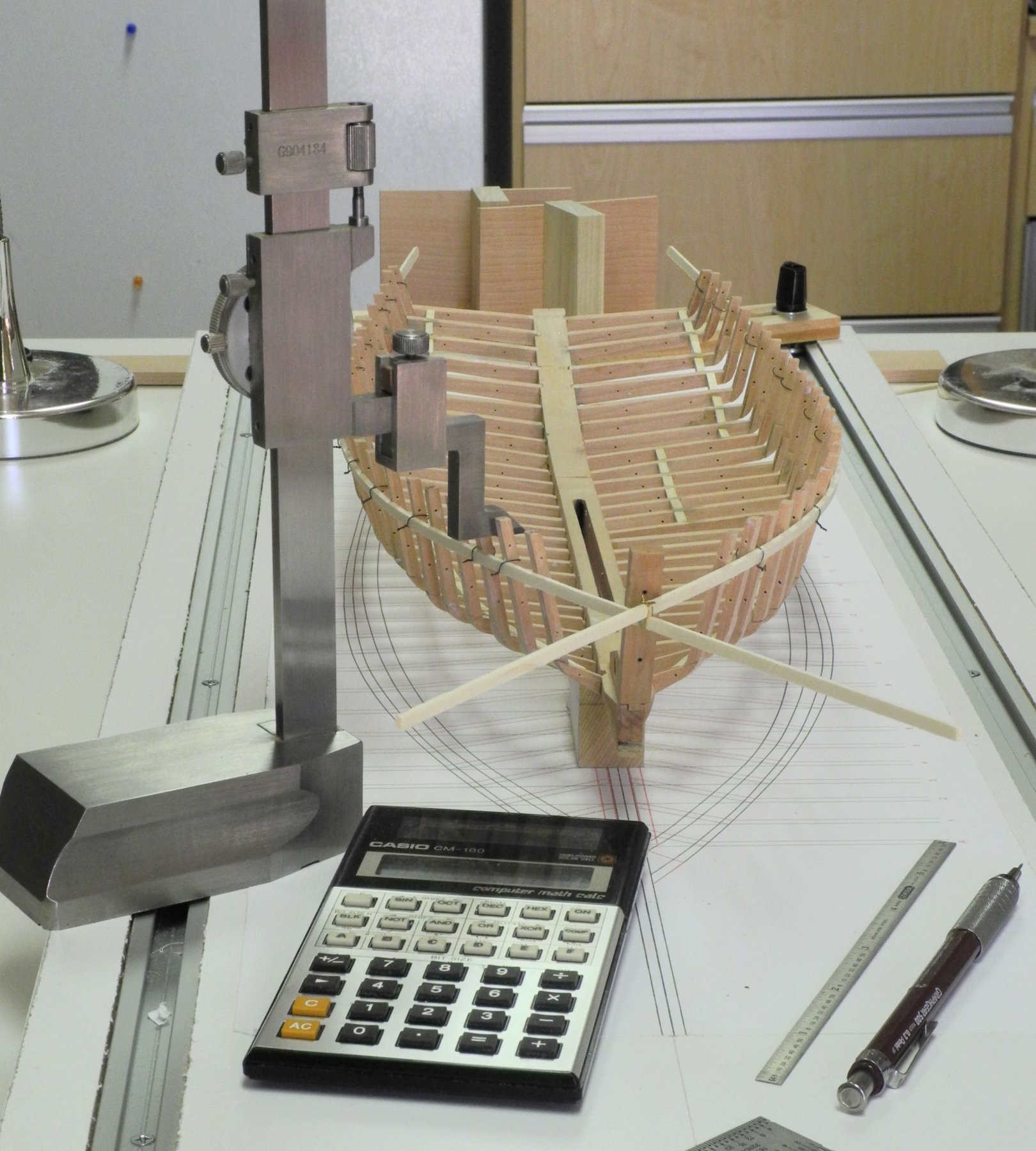
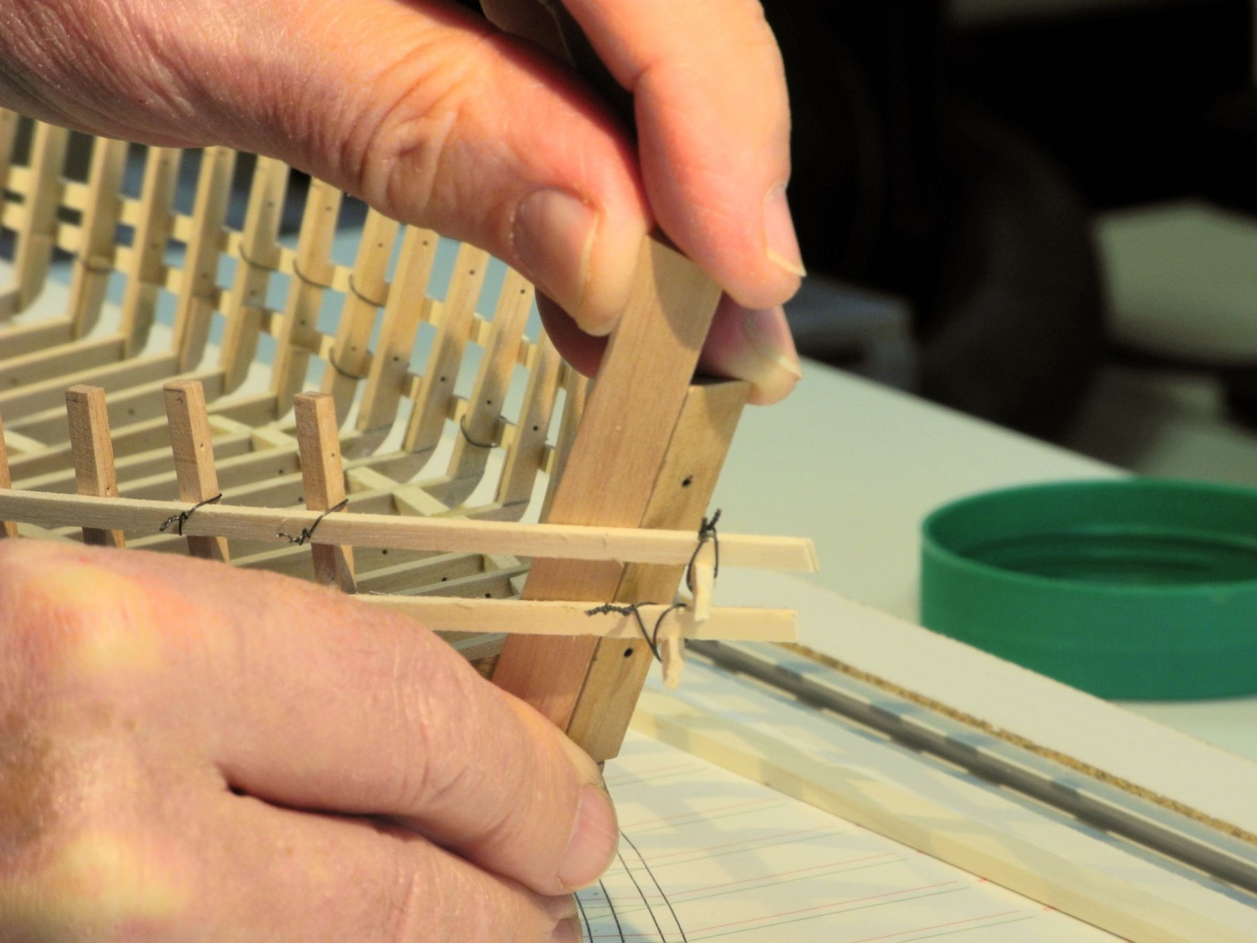
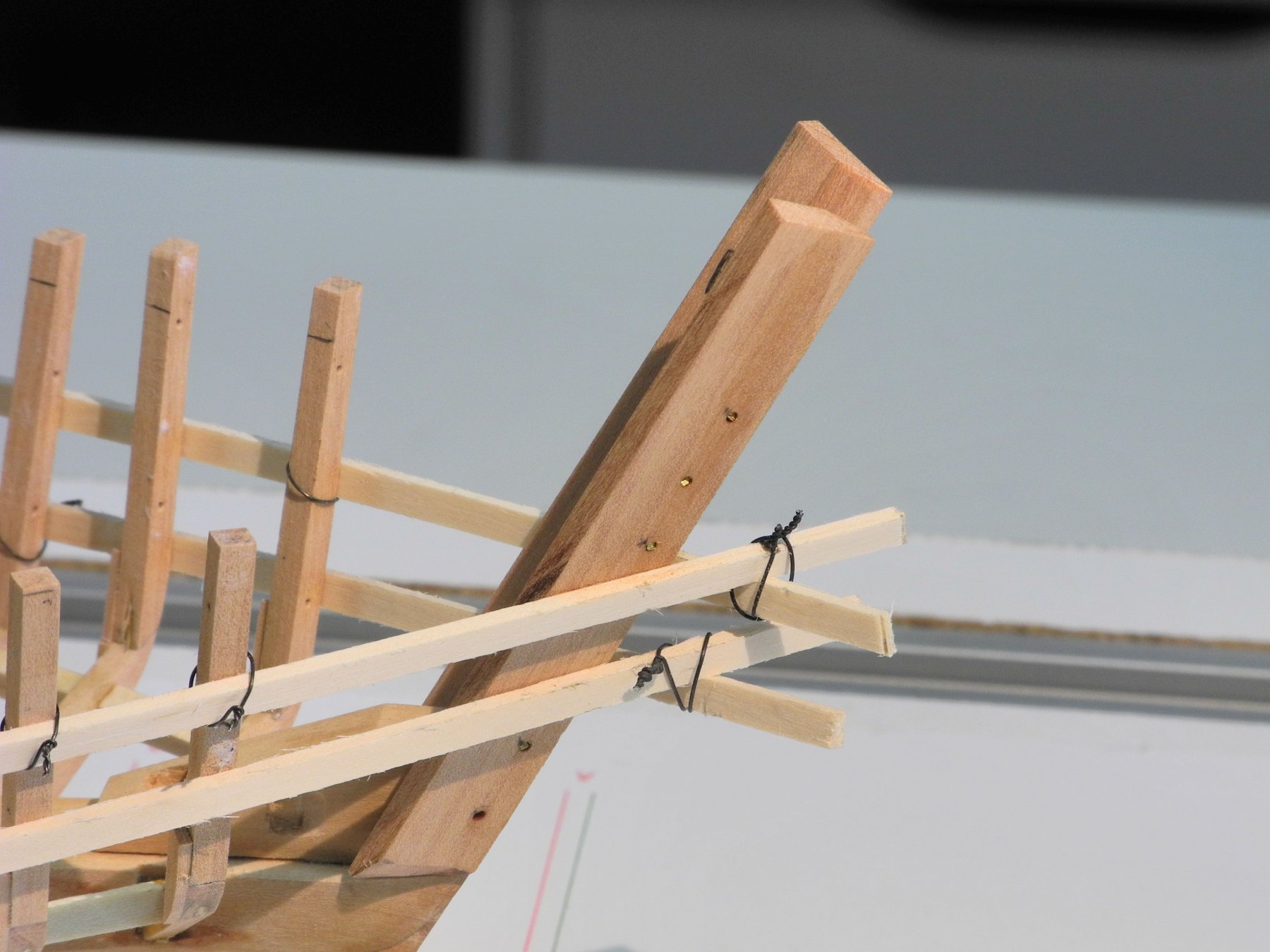
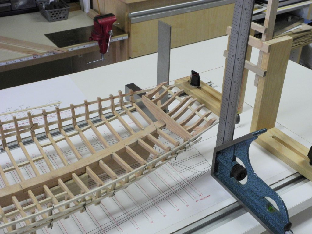
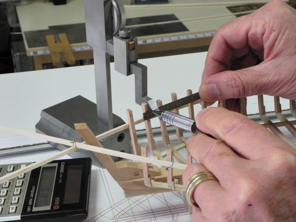
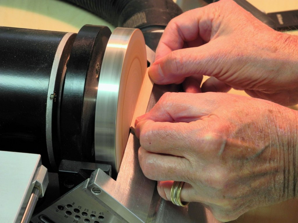
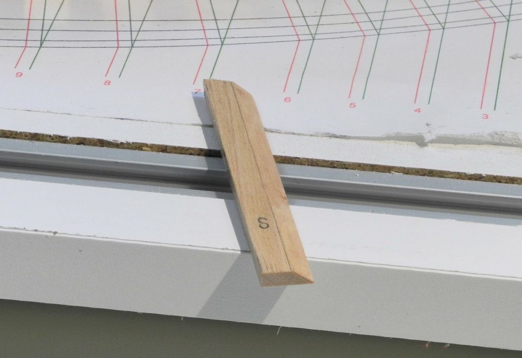
Part 12 – Knightheads It has been almost 2 weeks since my last post. The delay comes from two things: a lot of non-modeling activities and responsibilities; and a lot of time spent trying to work through the correct process for the next elements of the Kathryn build. Part 11 dealt with the complexity of the stern timbering and my questions on how to proceed. In addition to these questions, I was also a little perplexed about installing the knightheads – but these are simpler than the stern timbers, so I decided to tackle them first. Before working on the knightheads or the stern timbers, I thought it would be a good idea to mark off the location of the deck clamps on each side of the model. The clamps are 5-1/2” x 2-3/4”. The drawings show the height of the bottom of the deck, so I measured down from this value for each frame and used the tools in the following photo to mark the lower edge of the deck clamp on each frame. The height gauge could be set to the nearest 1/1000, so I calculated the measurement to this value and used a straightedge to mark the bottom of the clamp on each frame, as in the following photo. I set the height gauge to the appropriate value, laid the small straightedge against the lower edge of the gauge, and marked the line using a .003 pencil. In marking the clamp positions, it became apparent that the wires holding the temporary ribbands in place would interfere with the installation of the clamps. Since ribbands needed to stay in place until after the clamps were installed, it was necessary to move the ribbands to a better position. The solution was to install a full ribband lower down the hull from the original ribband and then, after removing the original ribband, to install a partial ribband on the forward frames – lower than the clamps, but high enough to achieve the correct fairing of the hull. The knightheads are 22” x 4”, and are tapered to fit against the inner stem (apron) at an angle that supports the side planks. In reviewing the drawings of Kathryn, I didn’t see any other point of attachment for the knightheads, and I felt that this tapered edge wouldn’t provide much strength to the knightheads. This question and the associated confusion on my part caused a delay of several days, so I finally asked a couple of friends who are very knowledgeable about skipjacks and Chesapeake workboats in general. The answer was very instructive, and I thought I’d share the entire answer: “by the time they were edge nailed to the apron, sandwiched between the sheer clamp and side planking, and notched into the front end of the covering board (sheer-plank) and king plank, and supported outboard by the log-rail and by the breast-hook(s) between them (often one under the sprit and/or one on top of the sprit.) they became a pretty formidable structure. i learned that their function was to support the bowsprit against sideways forces in the same way as the partners support the mast. also the extra thickness, and the nails therein, helped reinforce the bow planking against getting stove in and sprung out in the days of thick ice on the bay, and the hawse hole reinforcement was helpful too. back in the old days (1995) when i helped rebuild thomas clyde they removed the knight heads. they then made a new apron and all new planking but no new knight heads - i was appalled and dismayed but them good-old-boys told me they din't really do nothin' and they rotted out fast. as i was new on the job and my only expertise came from reading howard chapelle the night before, i backed off and the boat is still floating. [doesn't look as nice though. and we really did have any bad ice since then - and if we had they would have stayed in port anyway.]” So with my questions answered I made the knightheads. After the appropriate plank was milled it needed to be tapered to match the lay of the planks (based on the position of the ribbands). The disk sander was set at the maximum angle and the taper was sanded into the knighthead plank. This initial shaping didn’t provide enough angle, so the final tapering was done using a fine stump cutter on a rotary tool. The following photo shows the starboard knighthead ready for installation. I tired several approaches to clamping the knightheads for gluing to the inner stem (apron), but the angle made this difficult. I settled for using a couple of spots of medium viscosity CA glue in addition to the PVA glue. After holding the knighthead in place for about a minute, the CA then acted as a ‘clamp’ until the PVA finished curing. The following photos show the knightheads installed. In order to provide some additional strength on the model, 1/32” brass rod was used as structural bolts through the knightheads and into the inner stem, and was epoxied in place. Some progress has also been made on the stern timbers, and will be covered in the next post. Thanks everyone!


- 878 replies
-
- 21
-
-
Thanks, Ed. I appreciate the guidance. Now all I need to do is execute it! I'm going to try building the entire structure (including the strong back) before attaching it to the vessel. I think this may make it easier to do the fitting and shaping. I could leave shaping of the outermost timbers until the assembly is installed onto the keelson.
-
Ron and Sailor - I think you're right in the 'temp' pointing to a bolt - thanks. Ron - I don't see how the outside timbers could be 'free-floating' - in the photos of the first transom plank being installed they appear to be solidly in place before the plank can be attached to them.
-
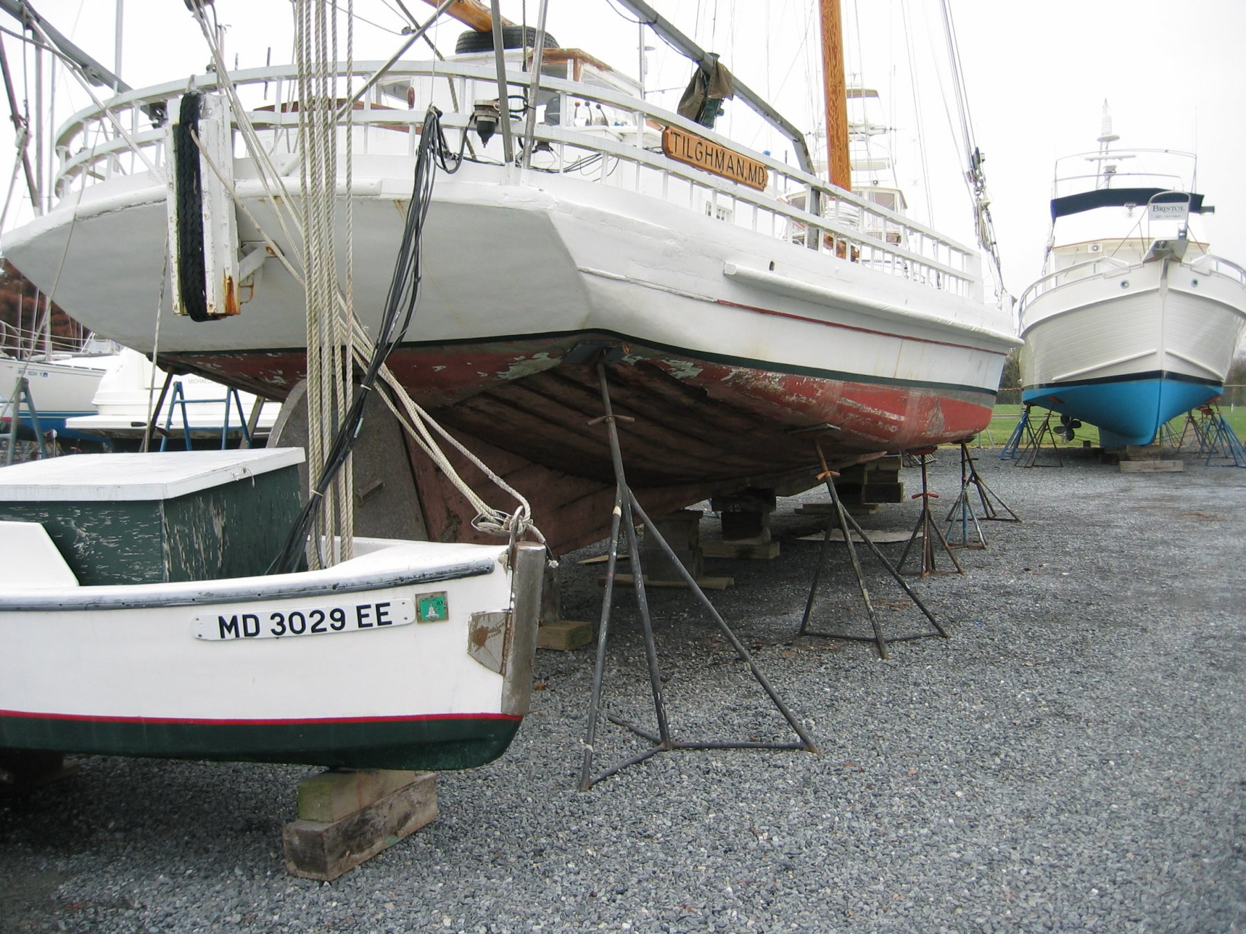
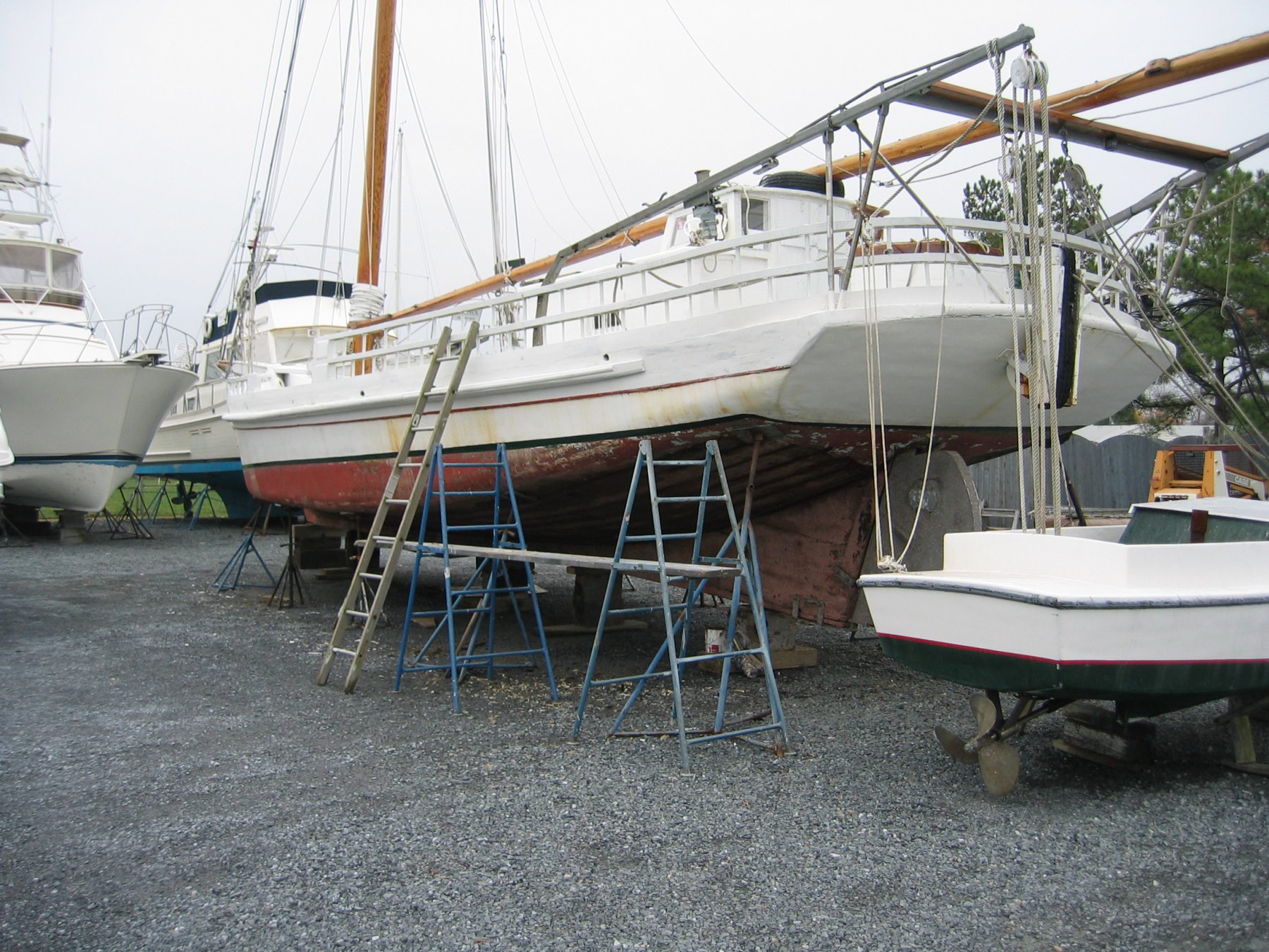
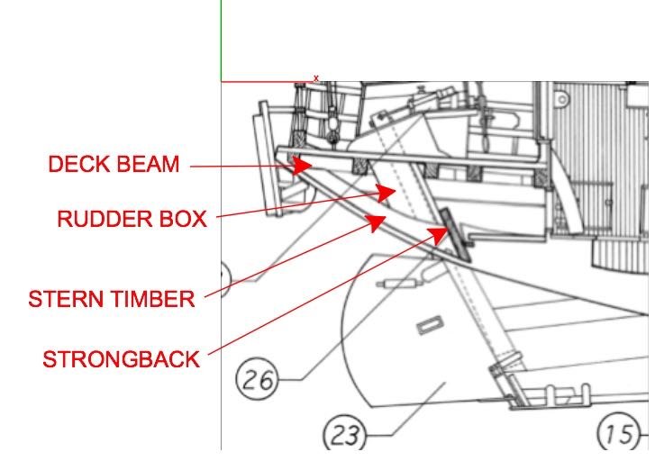
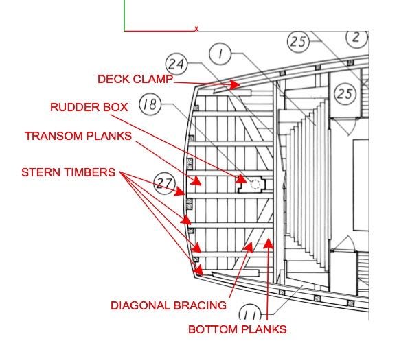
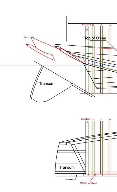
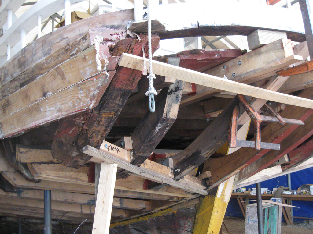
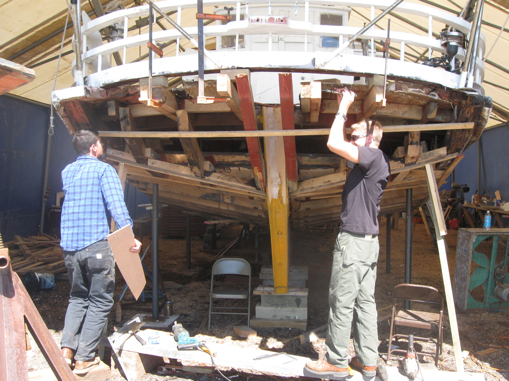
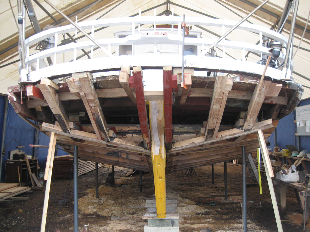
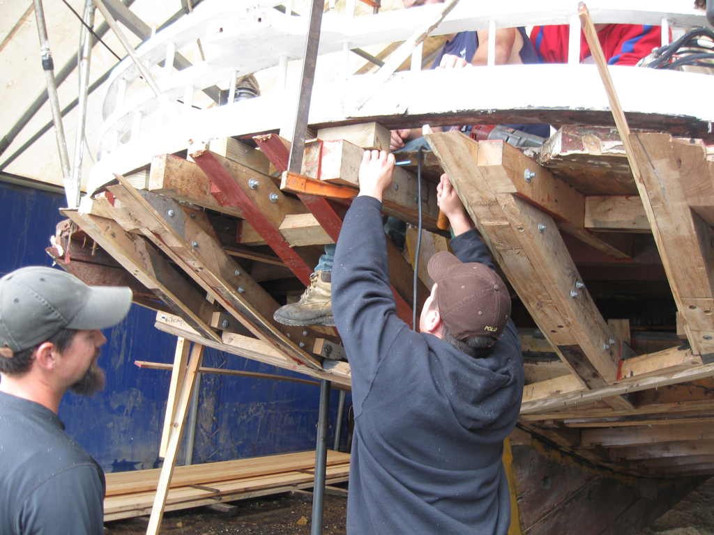
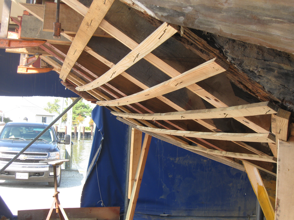
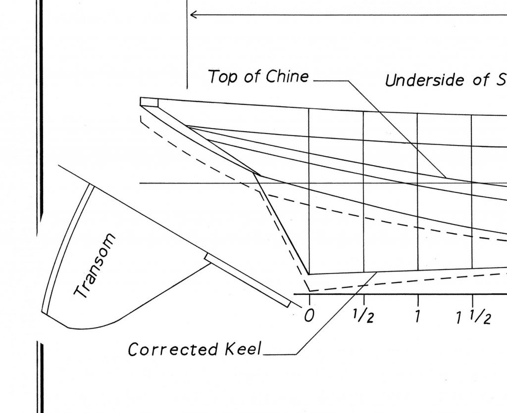
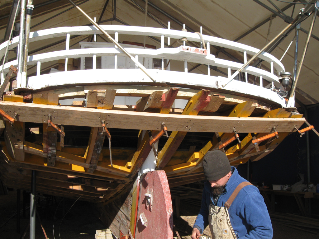
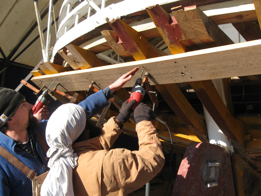
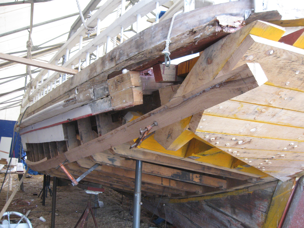
Part 11 – Stern Construction In preparing to work on Kathryn’s stern, I used the HAER drawings and photos from the recent reconstruction. These documents and photos raised a lot of questions about how this area was configured in the original construction, and also some questions on how to translate that to the model. The HAER documentation for Kathryn describes her construction as “Her rudder post is forward of the transom, a feature called an “inboard rudder” on skipjacks. She has a fully framed bottom with fore-and-aft planking.” The following photos show Kathryn’s stern before the reconstruction effort began. The HAER drawings show a profile view and a top view of Kathryn’s construction. The following is the relevant part of Sheet 4, showing the profile view of Kathryn’s stern construction. As can be seen in the photo, the stern timbers are somewhat curved, and are attached to a strongback that is installed behind the last frame and is attached to the end of the keelson. (This points out an error I made in the keelson construction: I left the end perpendicular, rather than slanted as in the drawing. This was a conscious decision, since I thought it wouldn’t be an issue, but I’m beginning to rethink that decision. I may decide to install a small wedge to give the strongback the required slant.) The top view from Sheet 5 shows more of the construction detail. There are a total of 8 stern timbers shown, 6 of which are attached to the strongback. The two central stern timbers flank the rudder box, and the next two timbers on each side appear to be evenly spaced, while the outermost stern timbers are spaced somewhat closer to the adjoining timber. The lines plans from the HAER documentation (Sheet 2) don’t show any of the stern timbers, so I added them when I redrew the plans for the model. The outermost timbers are not attached to the strongback, and I haven’t been able to determine how these two stern timbers are supported. The following photo from the reconstruction seem to show the old timbers, and it can be seen that these outermost timbers support the end of the side planking. The diagonal bracing appears to be used to support the aft edge of the bottom planking where it meets the transom, but from the above photos it is also difficult to see how the diagonals were installed. There are some pieces labeled ‘temp’ in the first of the above photos, located where the diagonal would be expected to be, and in the second photo it appears that the diagonal braces are let into the stern timbers by means of notches in those timbers. The diagonals in this photo appear to be new wood when compared to the other wood in the photo. The following photo appears to show some of the stern timbers being replaced. The two innermost timbers appear to be original, and the outermost timber on the starboard side appears to be original as well (there doesn’t appear to be any outer timber on the port side). From the following photo, it appears that the reconstruction tied the stern timbers into existing deck beams, which probably would not have been possible in the original construction. The following photo shows ribbands installed across the stern timbers, and illustrates the slight curve of the transom. This curve is also illustrated in the stern view of the profile plan shown in the lines plan. The following photos show the first new transom plank being installed. The curve of the transom can be seen in this photo. The next photo shows the transom planking completed, and a new chine plank being installed. The outermost port stern timber has been installed, but it’s hard to see what supports it. – it appears to be floating and not attached to the strongback. And another view of the transom, this time showing the outermost starboard stern timber, also illustrates how these outermost timbers don’t meet the strongback. The last photo of the transom shows a bottom plank being installed, and also appears to show how the bottom planks run flush with the lower part of the transom. So I’m still struggling with the following questions: 1. How should the stern timbers be drawn? Since they are diagonal, the length shown in the top view does not represent the actual length of the timbers. 2. Should the outer edge of the stern timbers be shaped to follow the slight curve of the transom? 3. How are the outermost stern timbers secured in place? 4. Should the diagonal bracing be installed by notching the stern timbers to accommodate them, or should they lay on the stern timbers? 5. Would it make sense to install the aft deck beams before the stern timbers? This might give a ‘landing place’ for the outer stern timbers, but it would also require the deck clamp to be installed first. I’m trying to build Kathryn as she was originally built, so following what is shown in the reconstruction photos will not always be appropriate. I would greatly appreciate any help in solving some of these questions. Thanks everyone!

- 878 replies
-
- 14
-
-
Hi Peter - so glad to hear that you're making progress. Your excellent models are a major reason I started scratch building, and I value your friendship.
-
Software recommendations
Mahuna replied to Sailor1234567890's topic in CAD and 3D Modelling/Drafting Plans with Software
I agree - TurboCad for Mac is excellent. I use the Designer version, which is 2D only and very affordable.