Mahuna
-
Posts
1,504 -
Joined
-
Last visited
Content Type
Profiles
Forums
Gallery
Events
Everything posted by Mahuna
-
 Ed, your level of detail continues to amaze. Thanks for 3+ years of sharing this great work with us.
- 3,618 replies
-
- 5
-

-
- young america
- clipper
- (and 1 more)
-
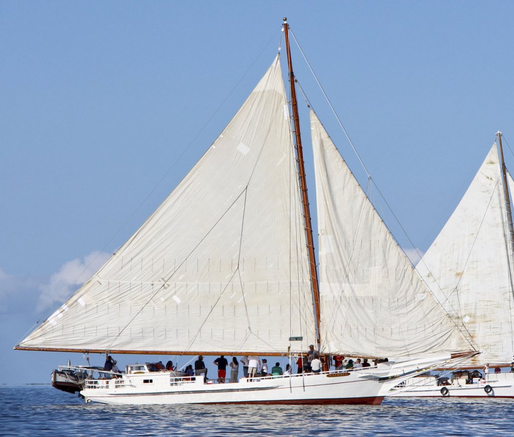
Thanks! You fit in very nicely with the skipjacks. I envy you and would love to get to the skipjack races some day. It's a great photo and shows how the boom sags - I'll have to remember that when I get to that point in the build.
- 878 replies
-
- 10
-
-
Thanks Bob and Druxey. This part went fairly quickly and smoothly - the tricky parts will be coming up.
-
And if you're going to show a skipjack set up for dredging, then the sails should not be fully deployed. Hadn't known that until I got the book. I also enjoyed the photos of the yawl boat at work.
-
Thanks Patrick! I really do enjoy the challenge of trying to build the model the way the full-size vessel was built - but I think you seem to enjoy the same thing on your models. When I get to the planking stage I need to determine how much of the work to show, or maybe just cover it all up.
-
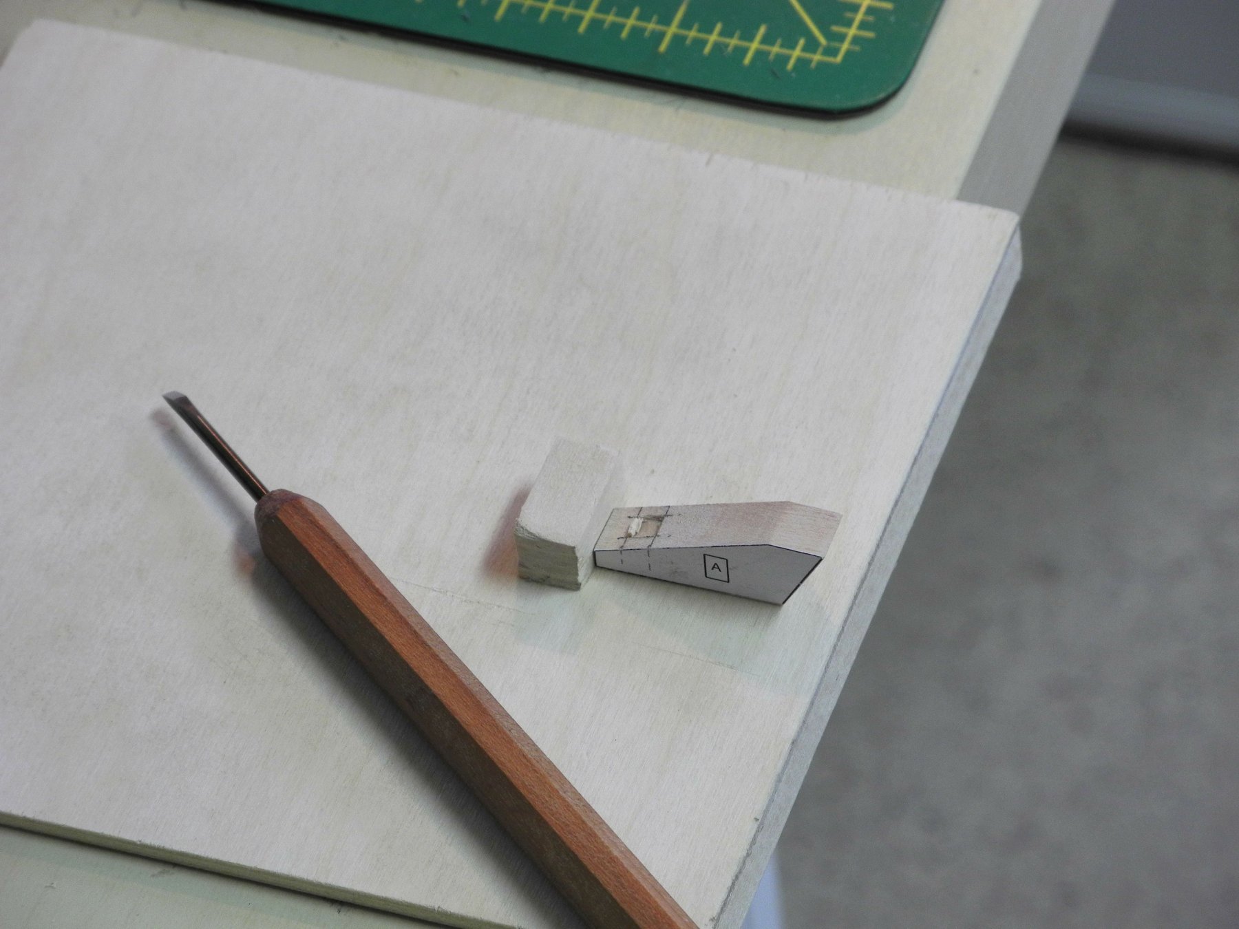
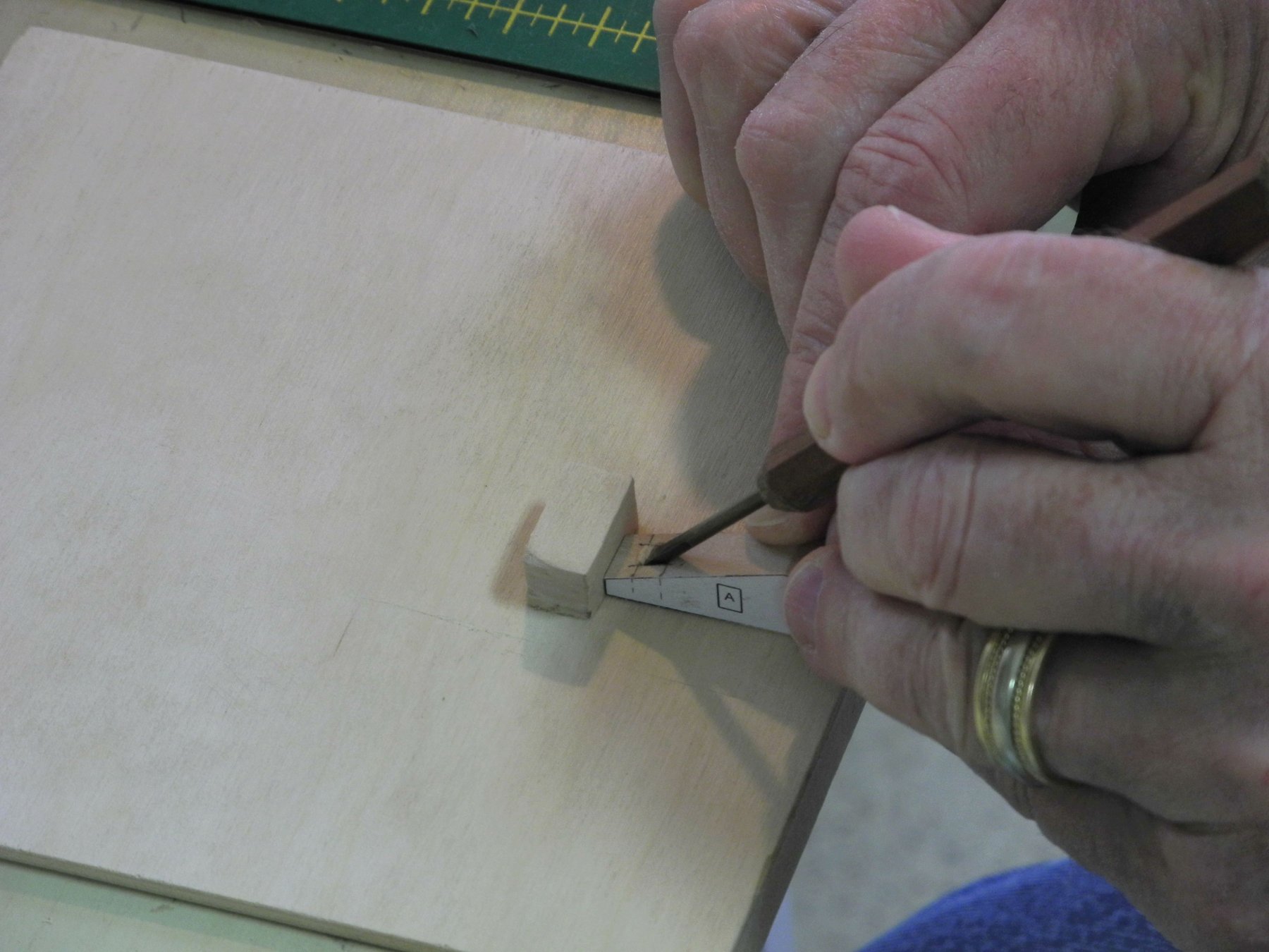
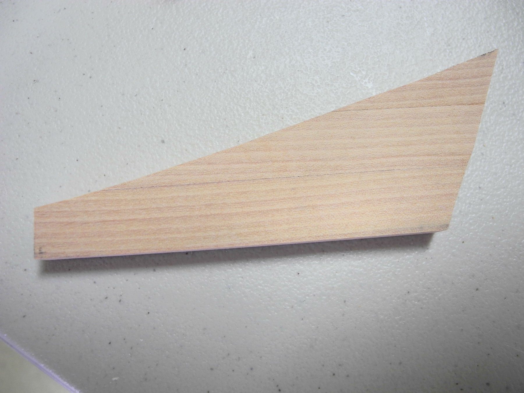
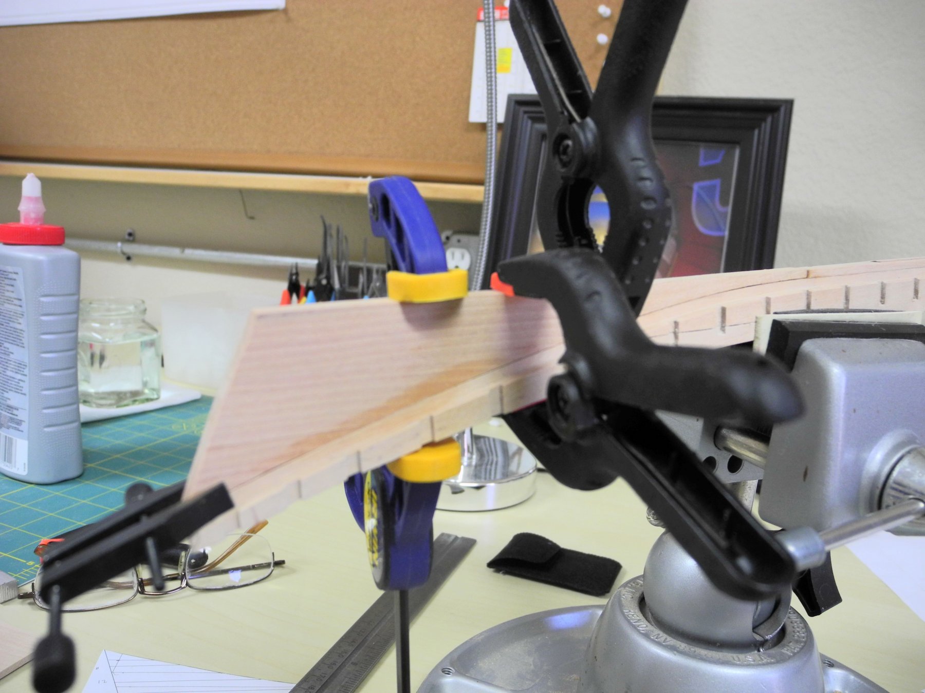
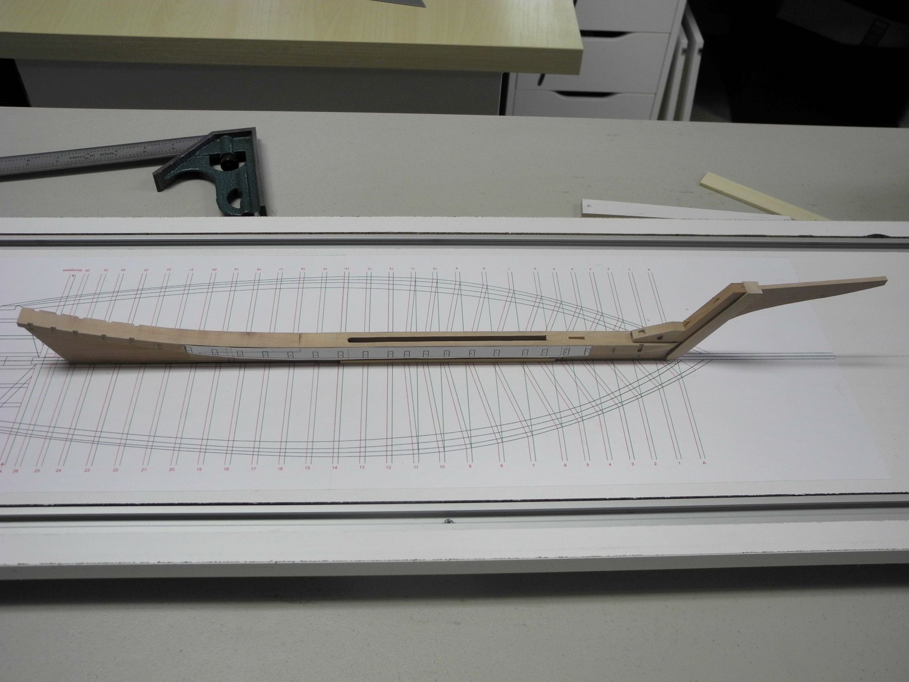
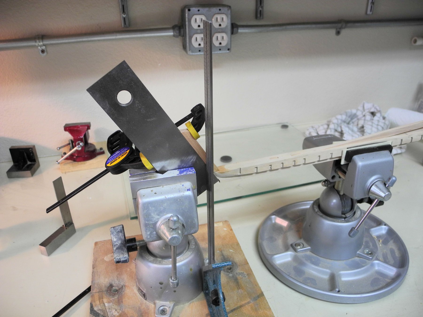
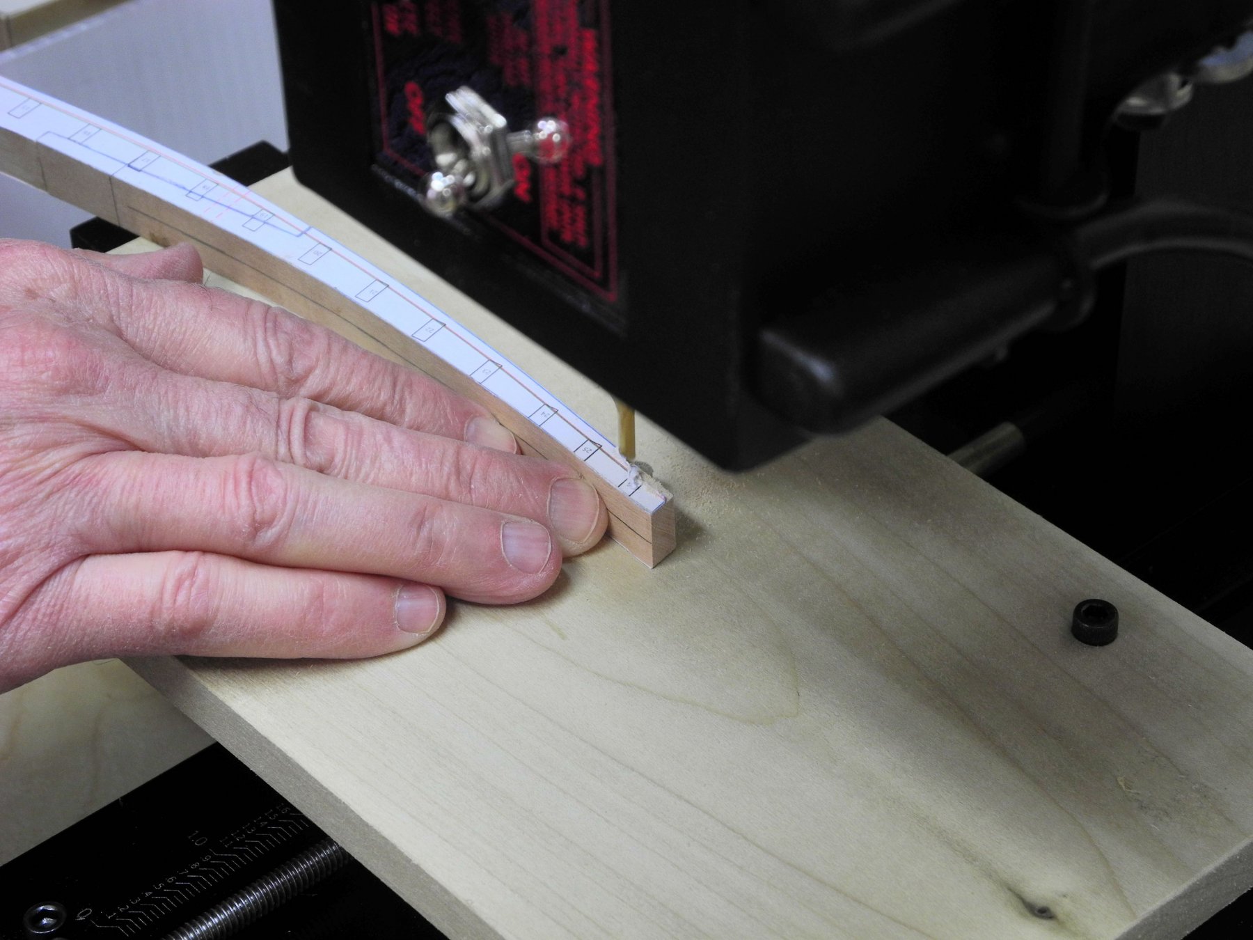
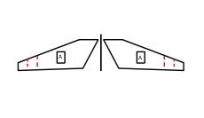
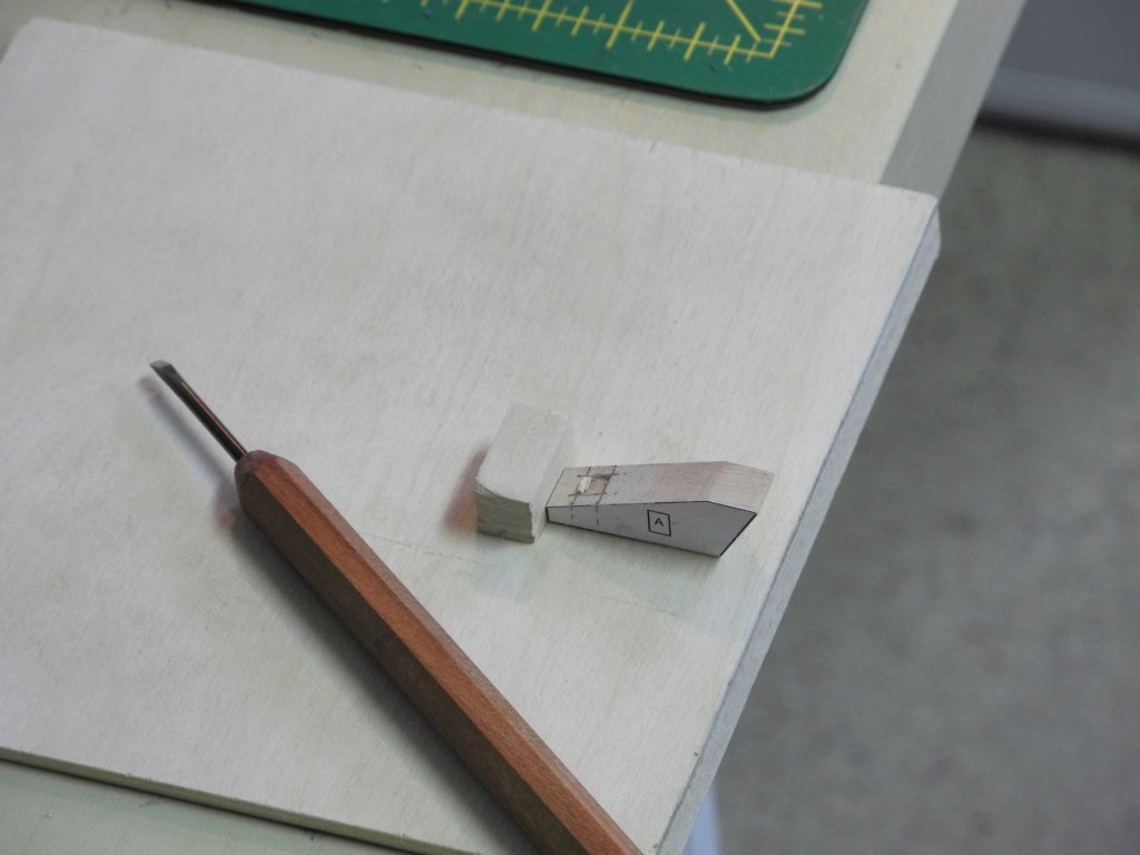
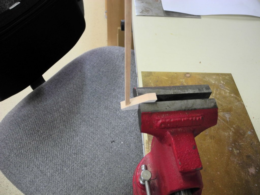
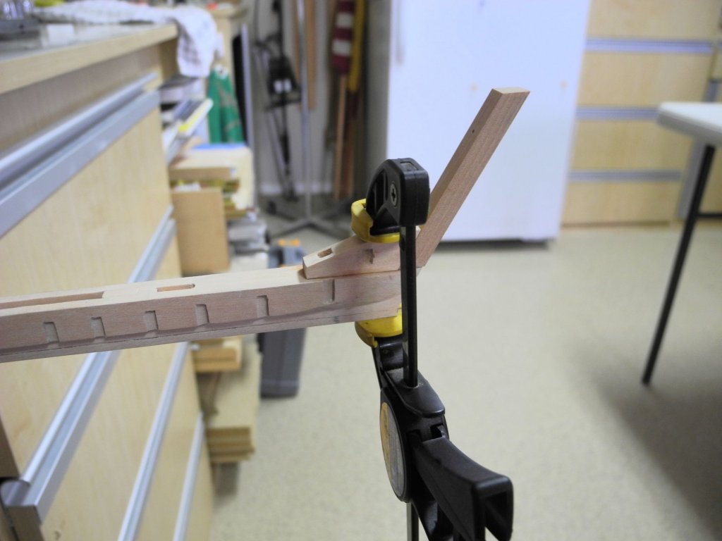
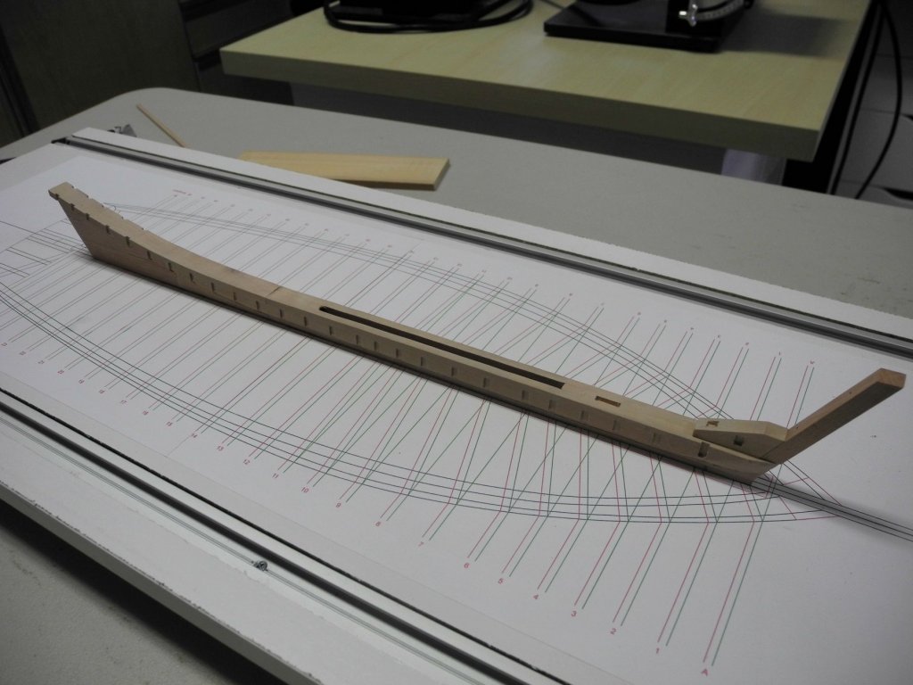
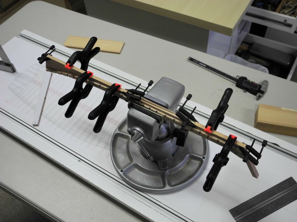
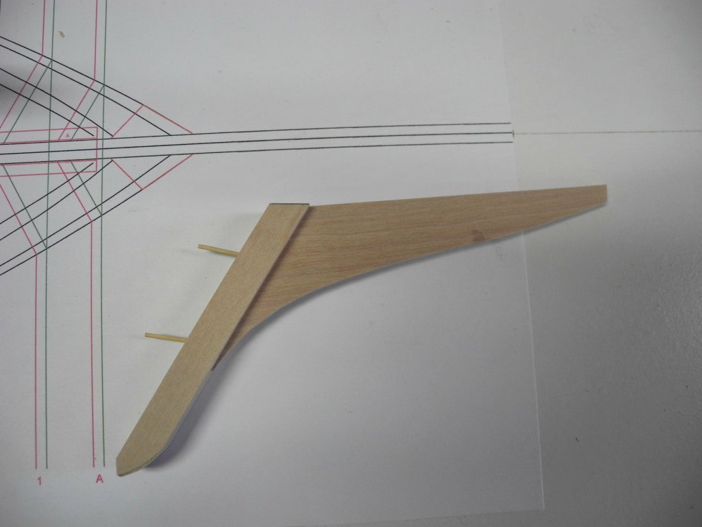
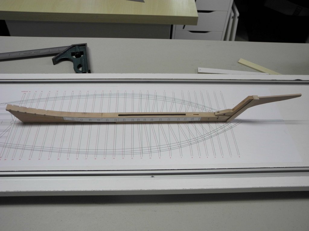
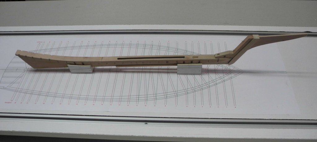
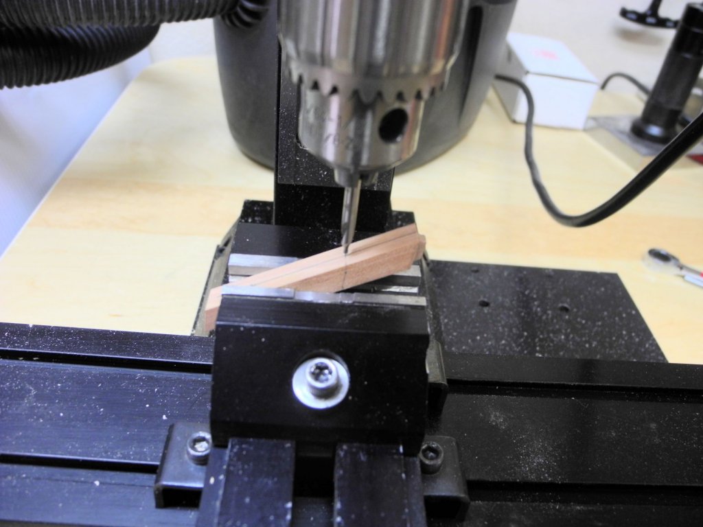
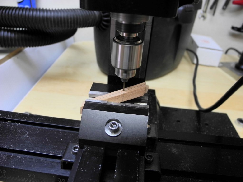
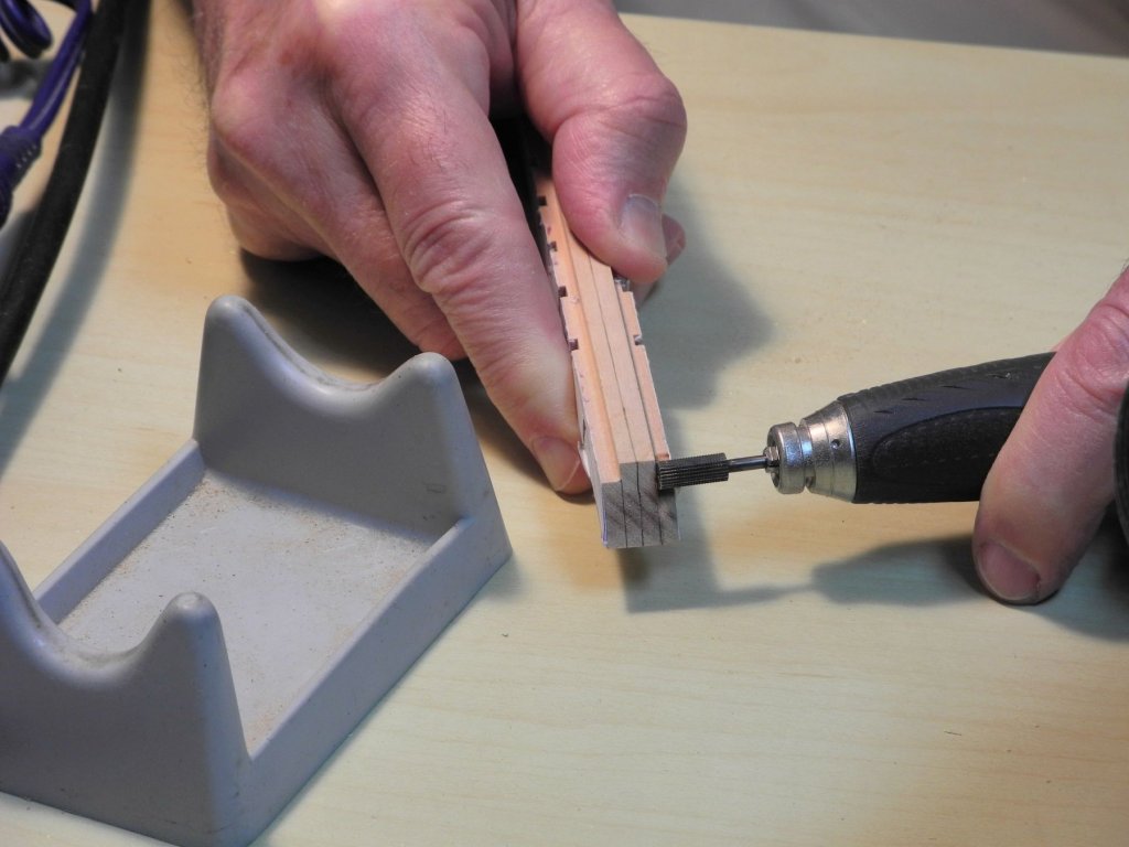
Part 5 – The Stem Knee, Keel, and Worm Shoe The stem knee supports the inner stem, has a 5” square socket to support the Sampson Post, and has a mortise on each side for the foreward-most frame. The following photo shows the stem knee drawing, which was mirrored for aligning the two sides of the knee. A small chisel was used to cut the socket and the frame mortises into the stem knee. Because the knee was fairly small, I used the work setup shown in the following photos. A 5” x 5” strip was used to check the accuracy of the socket for the Sampson Post. The stem knee was then glued in place. The rest of the keel (aft of the centerboard slot) was installed as two pieces. The first piece was installed at the beginning of the curve in the keelson. The aft keel piece was formed from 3 separate timbers. This aft piece was then glued in place. This completed the Keelson/Keel assembly. There is a ‘worm shoe’ installed under the keel, as a protection for the keel. This is made from pine and is only 2 “ thick. The following photo shows the worm shoe being installed. The cutwater and outer stem were fabricated, but only temporarily installed at this point. The outer stem will cover the plank ends, and will be tapered from the planks down to the width of the cutwater, so this work will be left until the planking is installed. The profile of the outer stem has been cut, and holes have been drilled to allow the outer stem to be temporarily mounted to the inner stem. In addition, a slot was milled in the forward face of the outer stem for installation of the cutwater. The following photo shows the completed Keelson / Keel / Stem assembly, with the temporary installation of the cutwater. And, finally, mounts were created to keep the keel assembly at the proper height from the shipway, and the assembly was mounted to the shipway. With the assembly now mounted in place, it’s time to start making and installing the frames for Kathryn. Thanks everyone for following along, and especially for the Likes and comments.


- 878 replies
-
- 28
-
-
Hi Ron I have the 2005 version, and in the forward the writer mentions that Burgess originally intended 2 books - part 1 and part 2. Part 1 was the book published in 1975. His widow and his son decided to publish the photos intended for book 2 in an expanded version of the original book, which became the 2005 version.
-
Thanks, Patrick. It's great to finally get started on the build after lots of planning and drafting.
-
Thanks Druxey - yes, let's keep it our little secret. Thanks 'Mischief'. I have the book, and the photo of the bow on page 238 answered some questions I had about the run of the bottom planks, and also illustrated how the outer stem serves to cap the hull planking, eliminating the need for a rabbet on the bow.
-
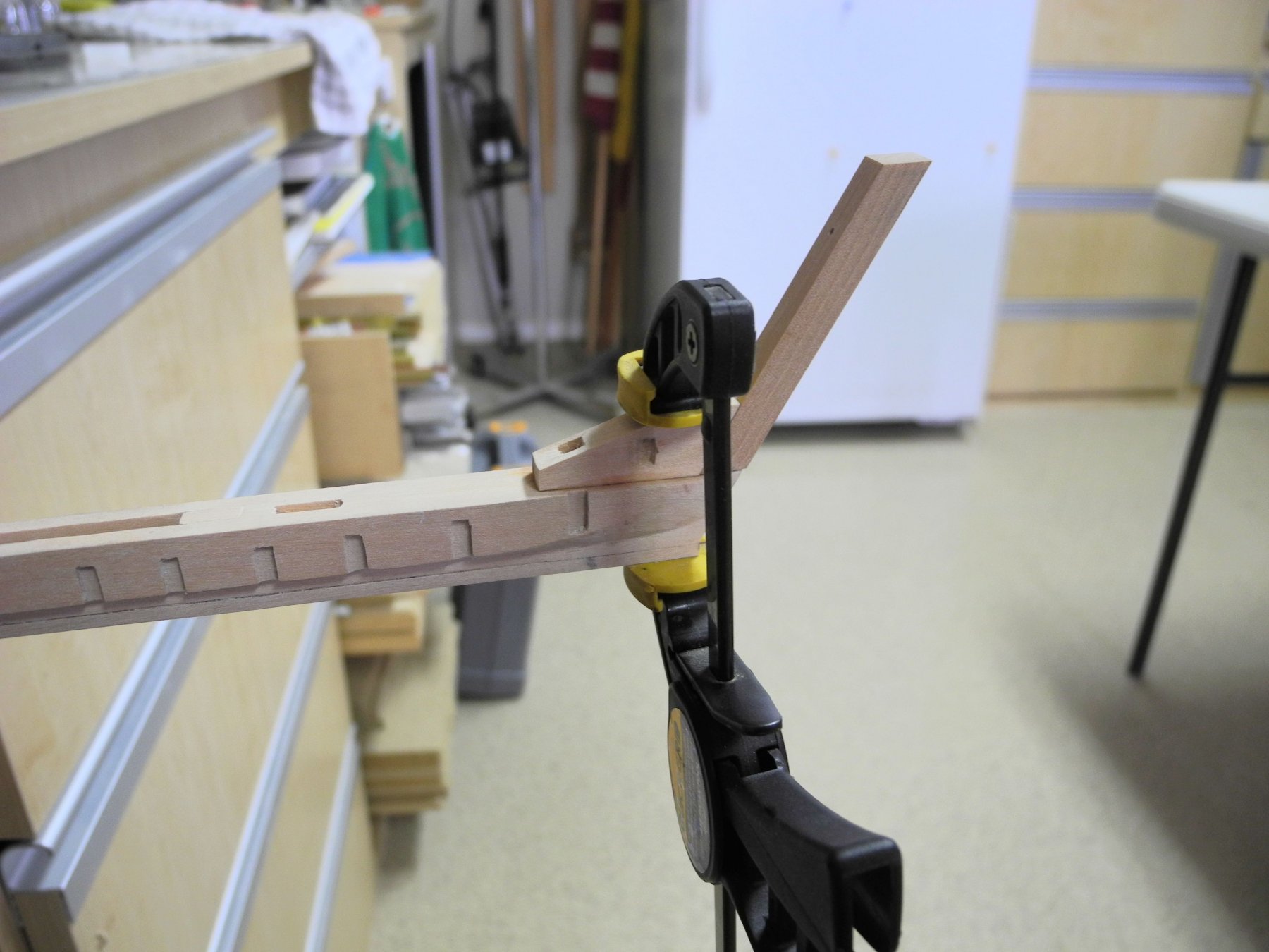
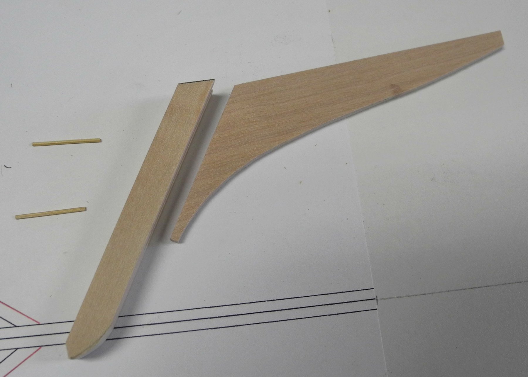
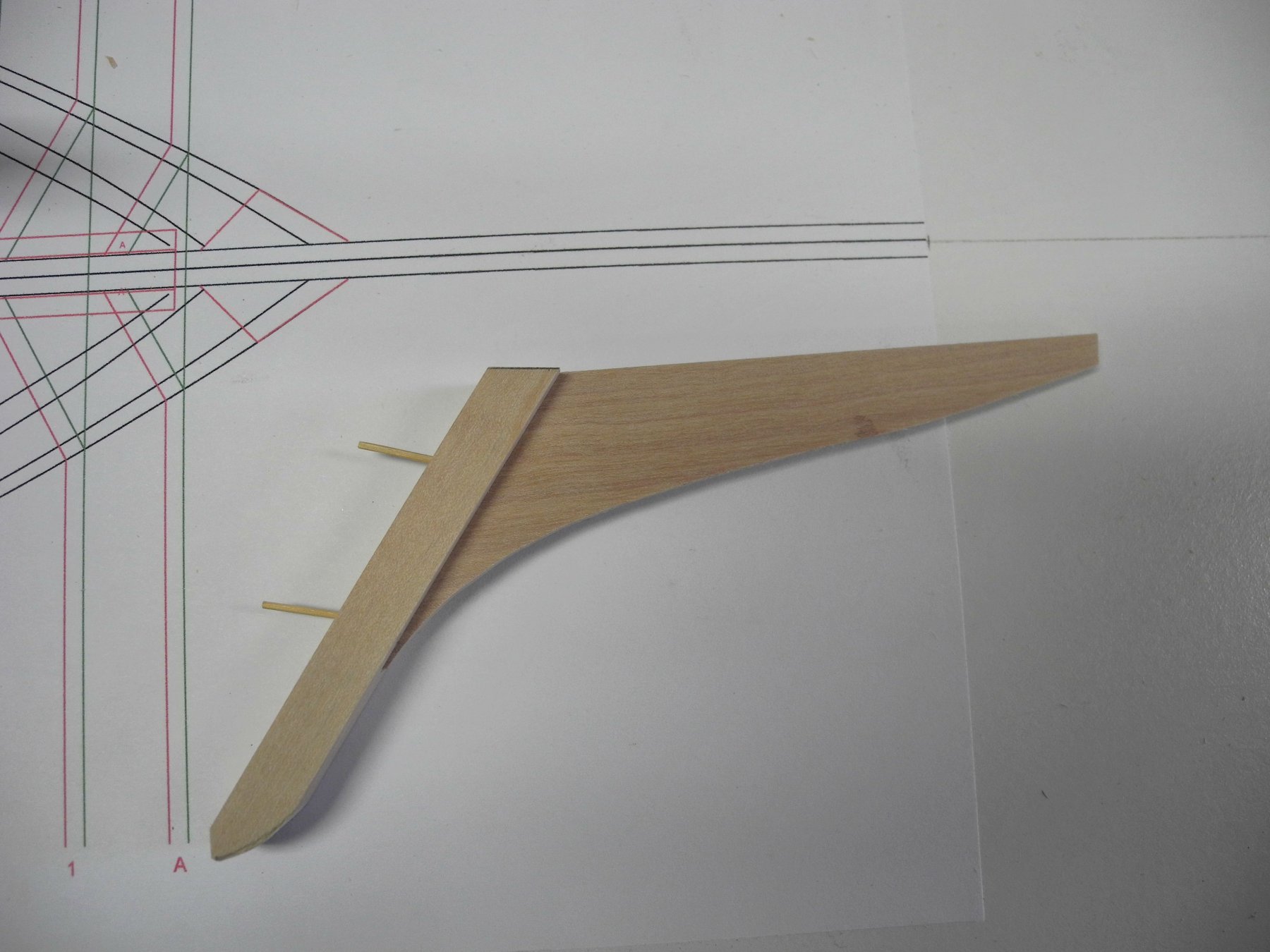
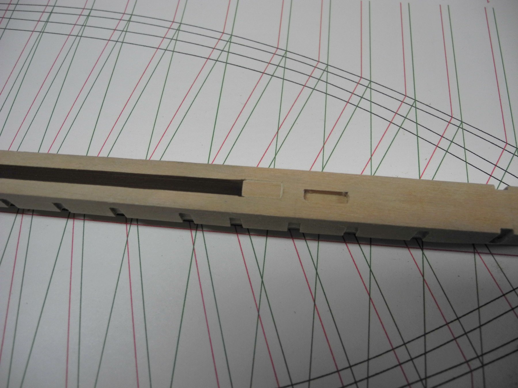
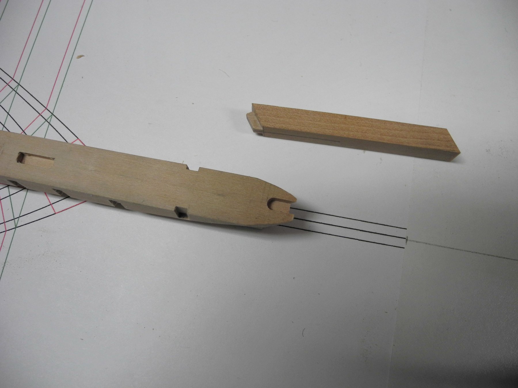
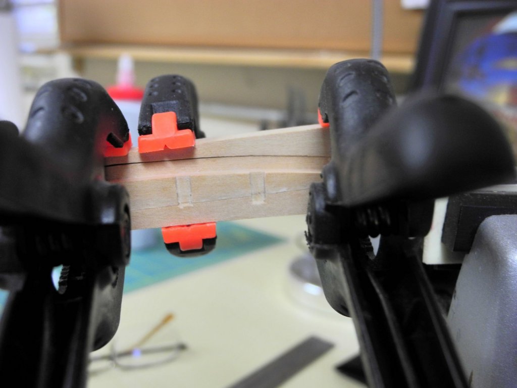
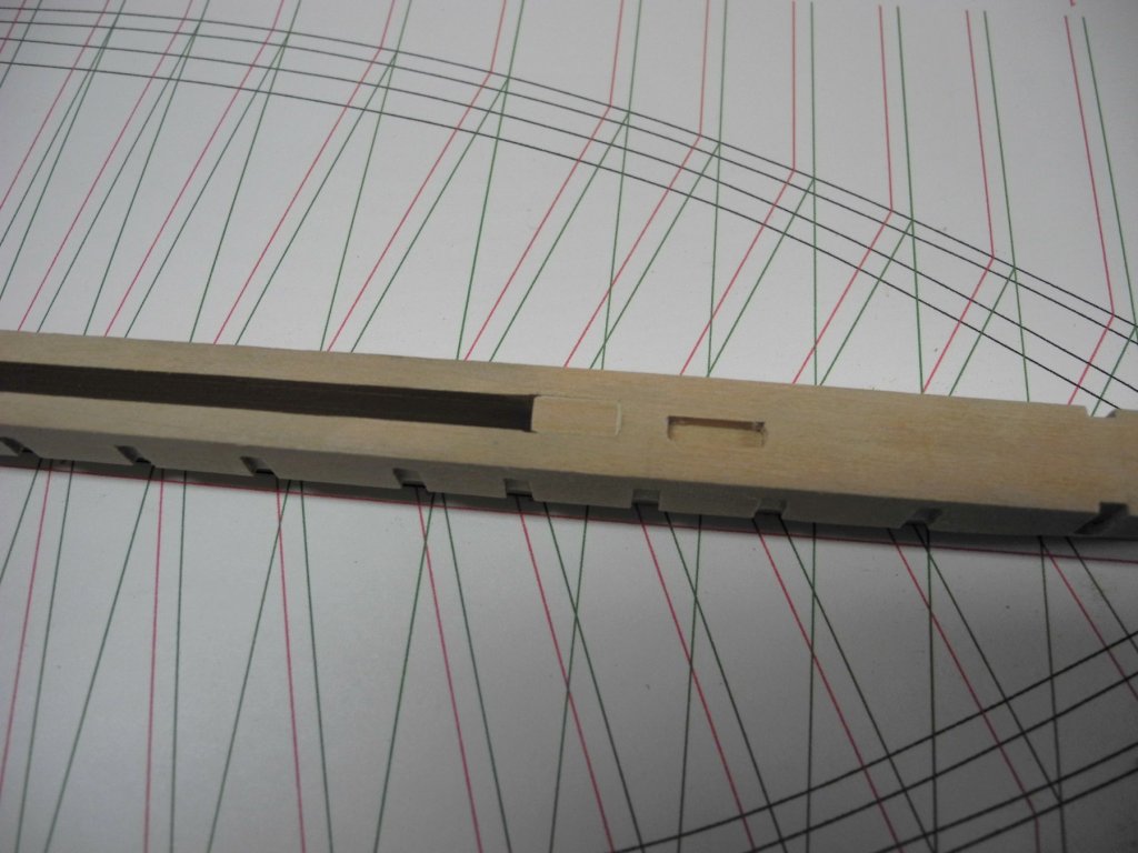
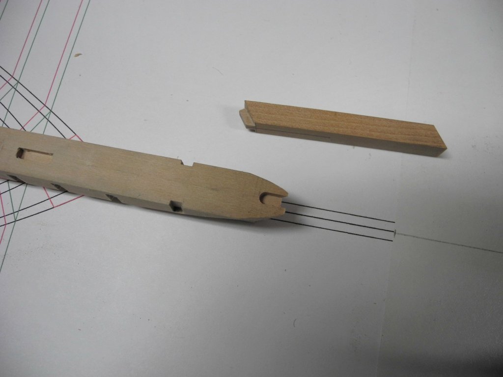
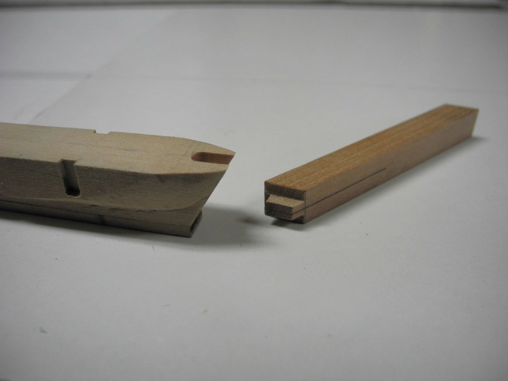
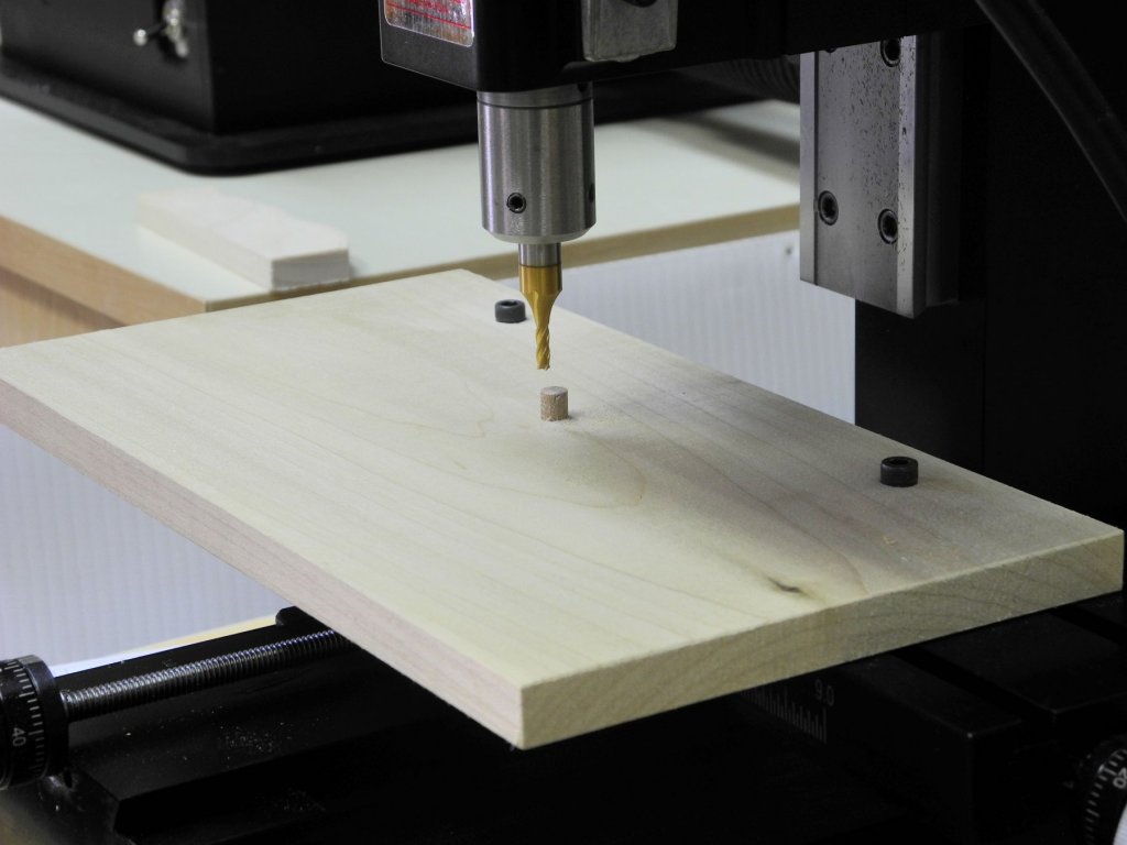
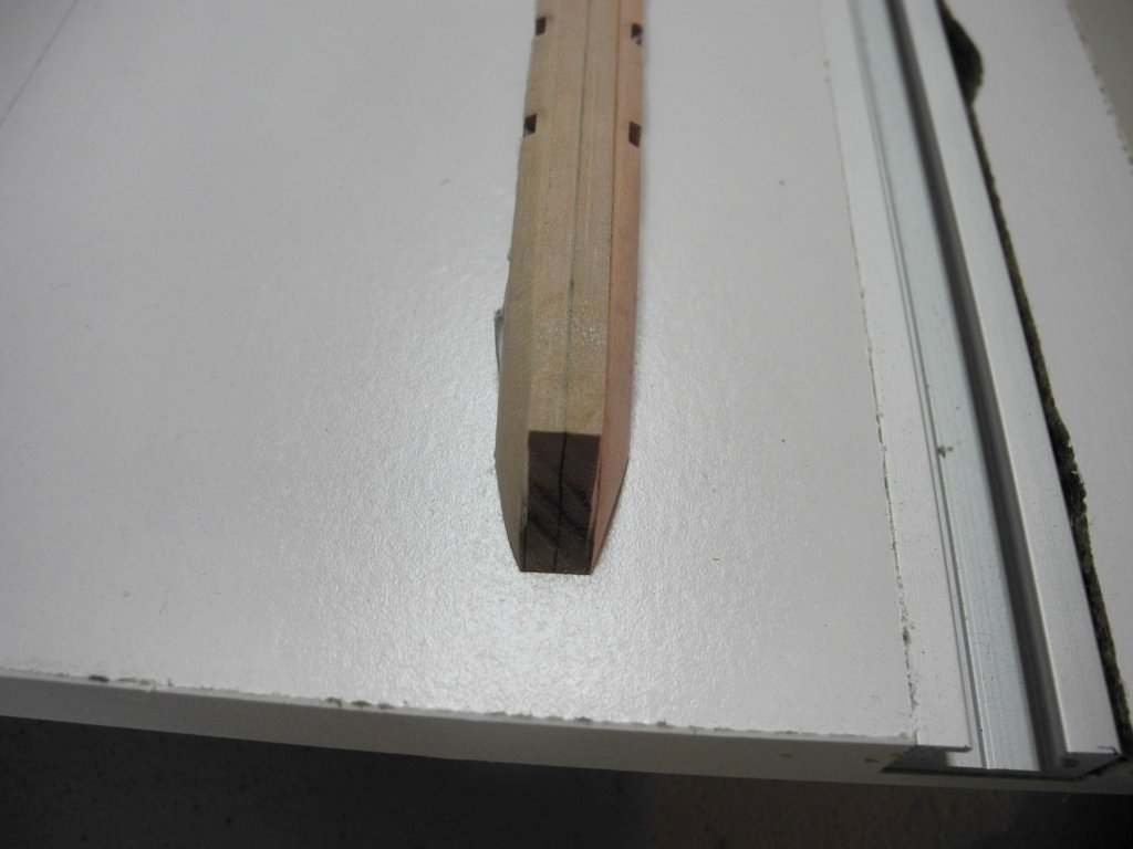
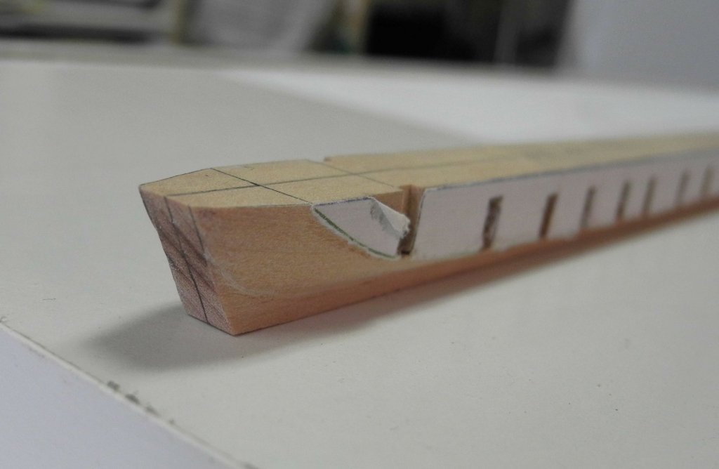
Part 4 – The Keelson – cont’d I should have mentioned wood selection in the prior post. Kathryn has a mixture of oak and pine, with the oak being used primarily in structural components. The HAER documentation does a good job of identifying the type of wood used for each component. I’m using madrone (very similar to pear) for the components made of oak, and castello for the pine components. Madrone normally is fairly pink, like pear, but my current stock of madrone is much paler than what I’ve used in the past. The centerboard slot is cut through both the keelson and the keel, so the first task was to add the keel in the area of the centerboard slot. The oak keel is very thin from the bow through the area of the centerboard slot – only 3” thick. Since the thickness is consistent in this area a single piece could be milled. The following photo shows this keel piece being glued in place. The milling cutter would not mill the entire depth of the slot from the top of the keelson – the keelson would need to be flipped for completion of the slot. Pilot holes were drilled through the keelson at each end of the slot location – this enabled proper location of the slot when the keelson was flipped. The following photo shows the centerboard slot being milled. The mast step in Kathryn is actually a longitudinal mortise, so this was also milled at this time. The following photo of the completed keelson shows the centerboard slot and the mortise for the mast step. In the interest of full disclosure, I need to admit that I cut the centerboard slot too far forward after misreading one of the various marks I had made on the keelson. The end of the centerboard slot was in the proper place, so this was easily corrected by inserting a small plug in the forward end of the slot – as seen in the following photo. Kathryn’s bow consists of an inner stem, and outer stem, and the cutwater. All of these components will be made of oak. The inner stem sits on the keelson, and is supported by a stem knee. The inner stem needed to be shaped so that it inclines at the same angle as the forward edge of the keelson. I was also concerned about the inner stem being sufficiently secure, so a tenon was formed on the stem and a corresponding mortise was cut in the keelson, as shown in the following photos. I was also concerned about attaching the outer stem, which will lie against the inner stem, so 2 pilot holes were drilled in the inner stem for aligning the outer stem in a later step. These holes needed to be fairly horizontal, so the inner stem was held in the milling vise at the approximate angle of installation. A centering drill was used to assist in drilling at that angle. Once the centering drill started the hole, a #60 drill was used to complete the drilling. The setup for gluing the inner stem to the keelson was a little unusual, since it was necessary to ensure that the inner stem and the forward face of the keelson stayed in the proper alignment. A parallel bar was set in a vice for this alignment, and the keelson/stem knee combination was aligned with the bar. A square was also used to ensure that the stem knee stayed vertical on the keelson. The clamping setup can be seen in the following photo. The following photo shows the keelson with the inner stem knee installed. The next work will include the installation of the stem knee and completion of the keel assembly.


- 878 replies
-
- 35
-
-
Thanks Druxey. I've been looking forward to being able to get this build under way. Hi Brian. Yeah, I thought about that earlier today, and have included a description of the wood in the next post.
-
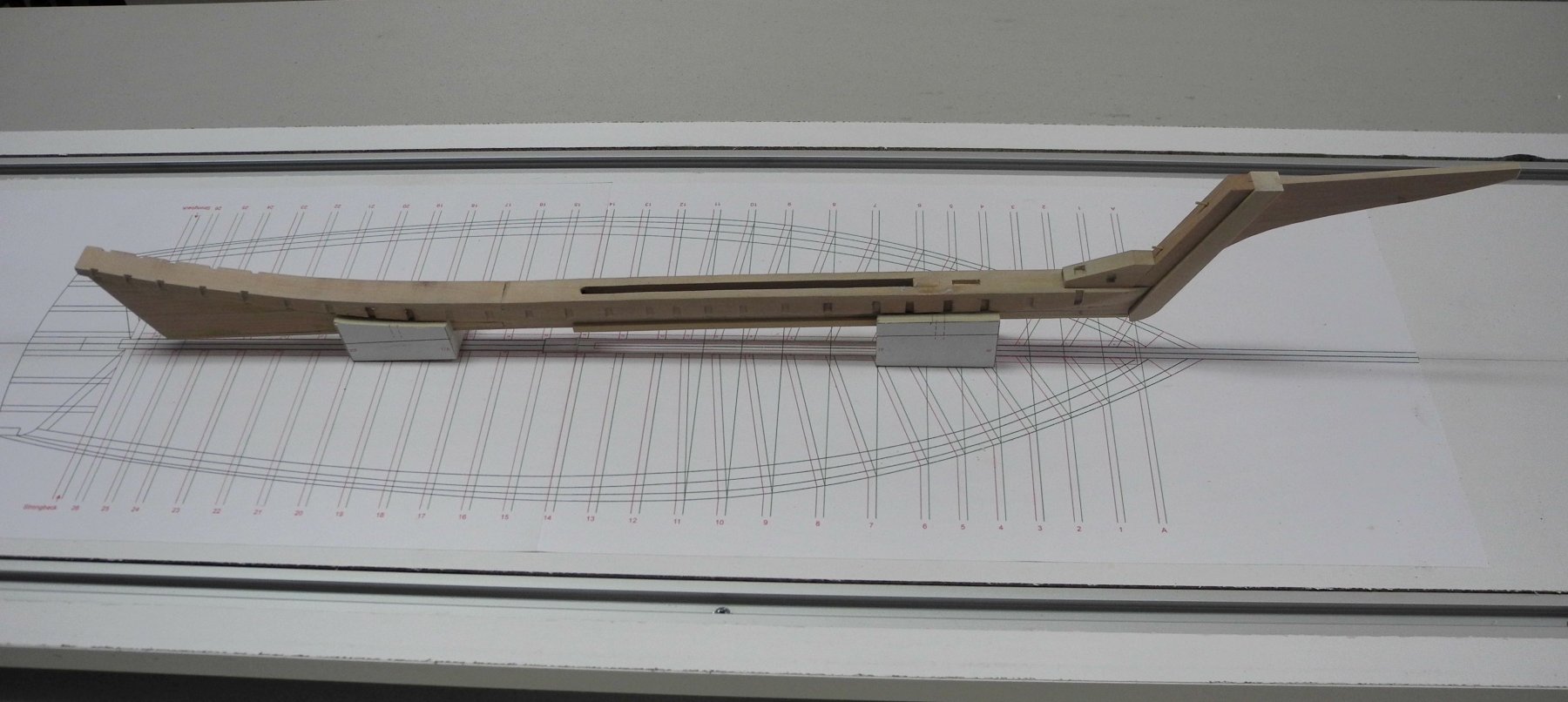
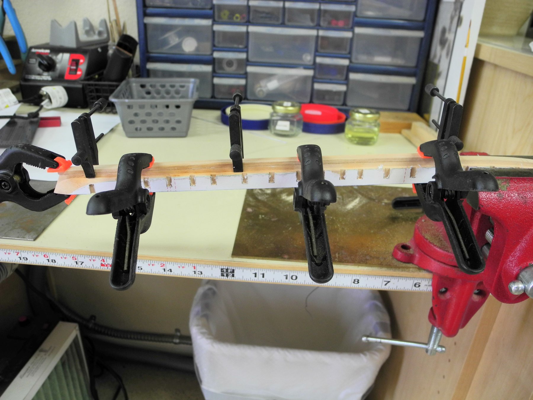
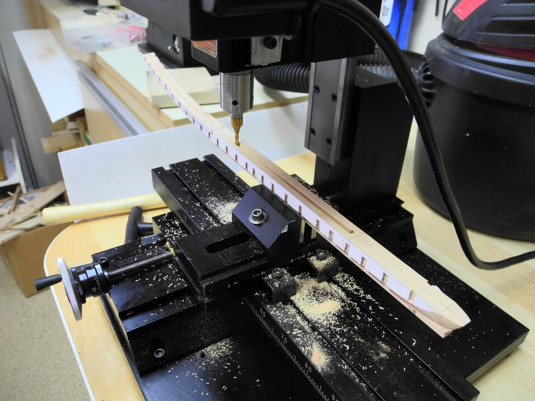
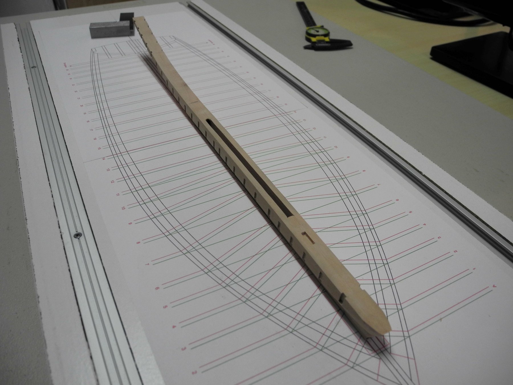
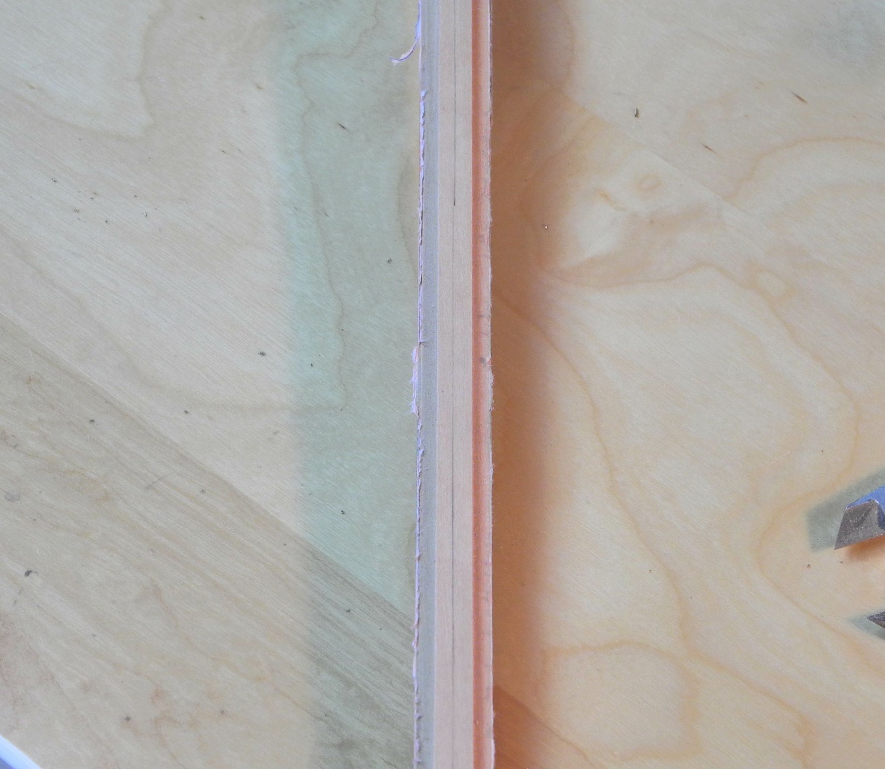
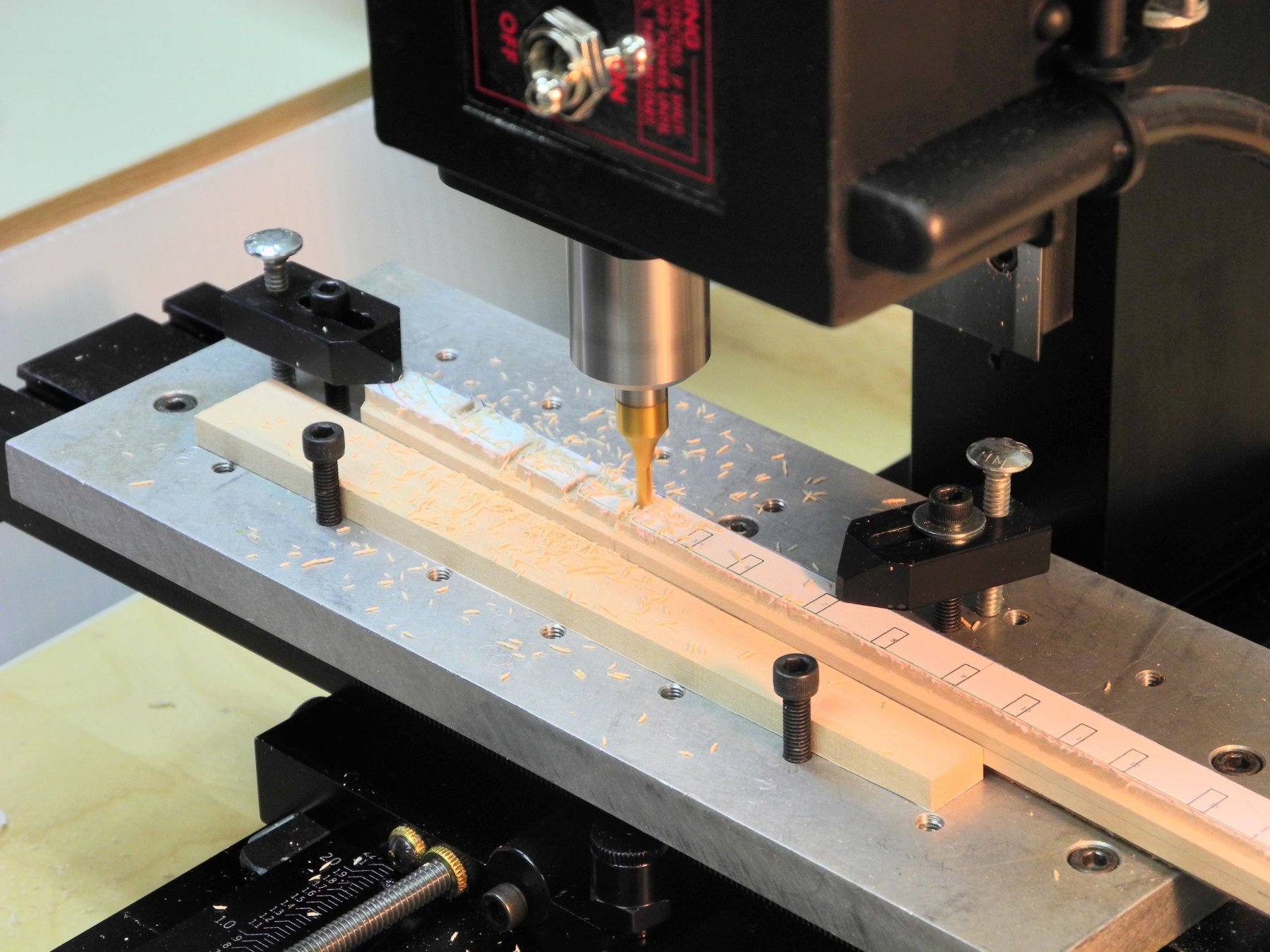
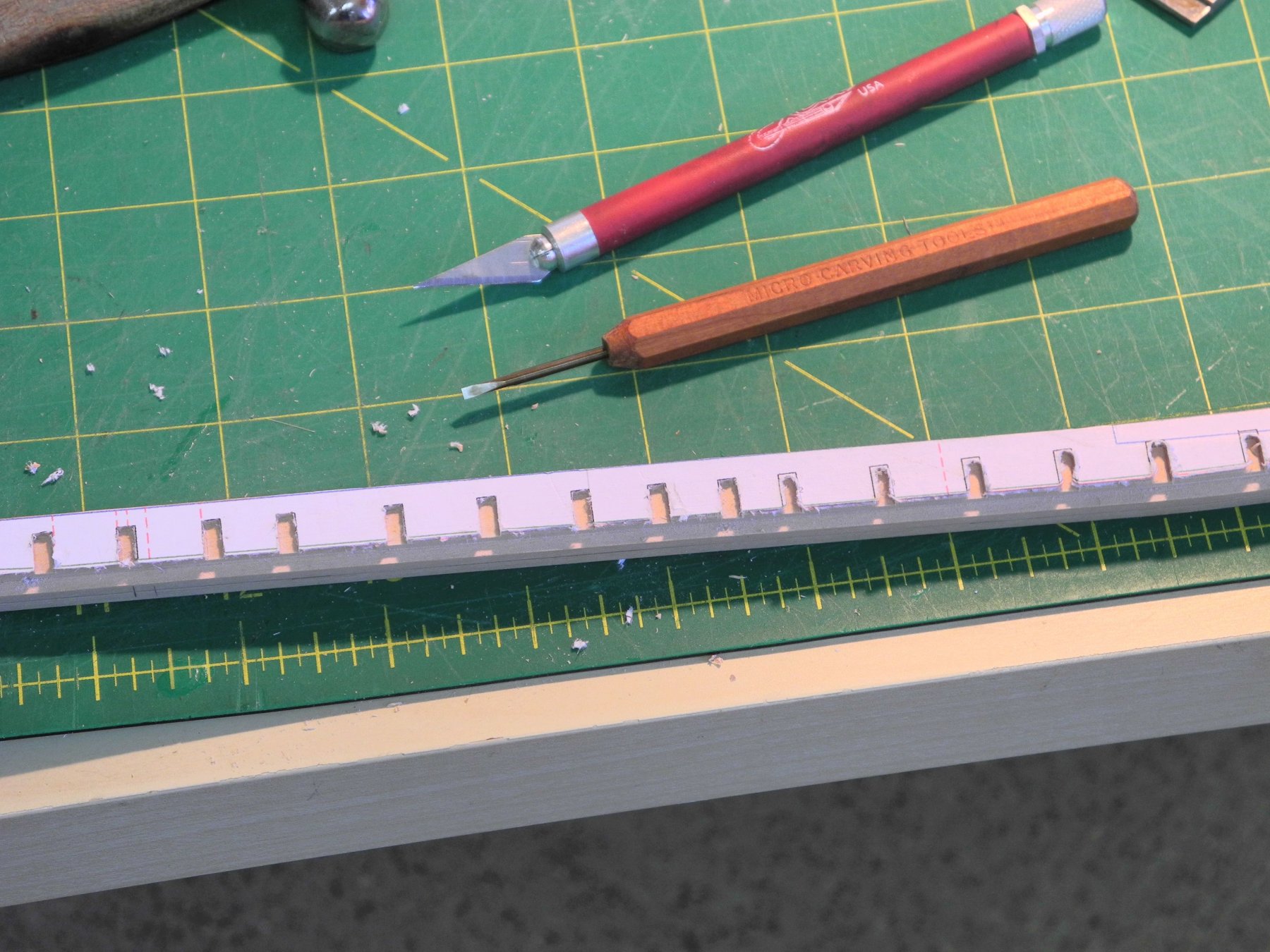
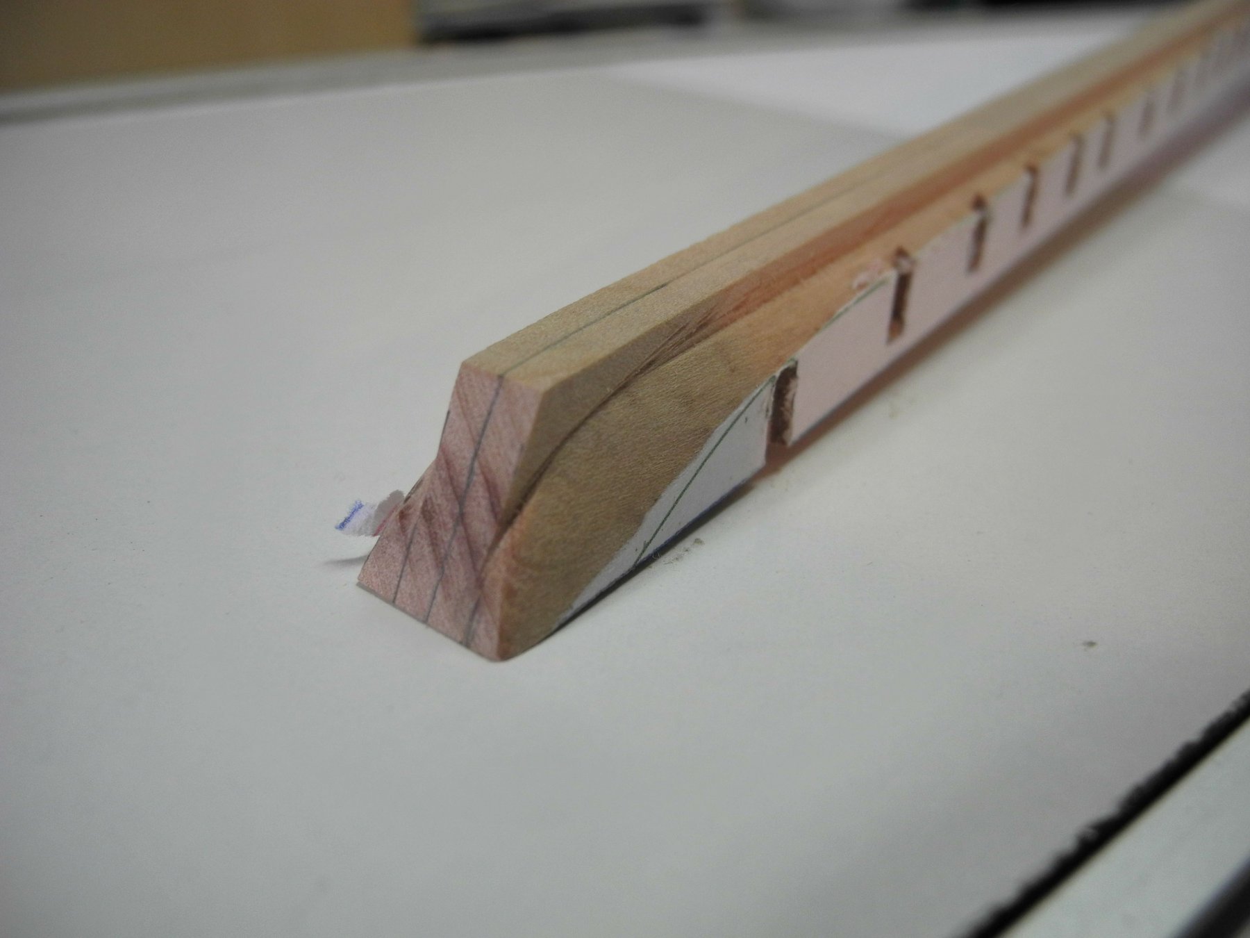
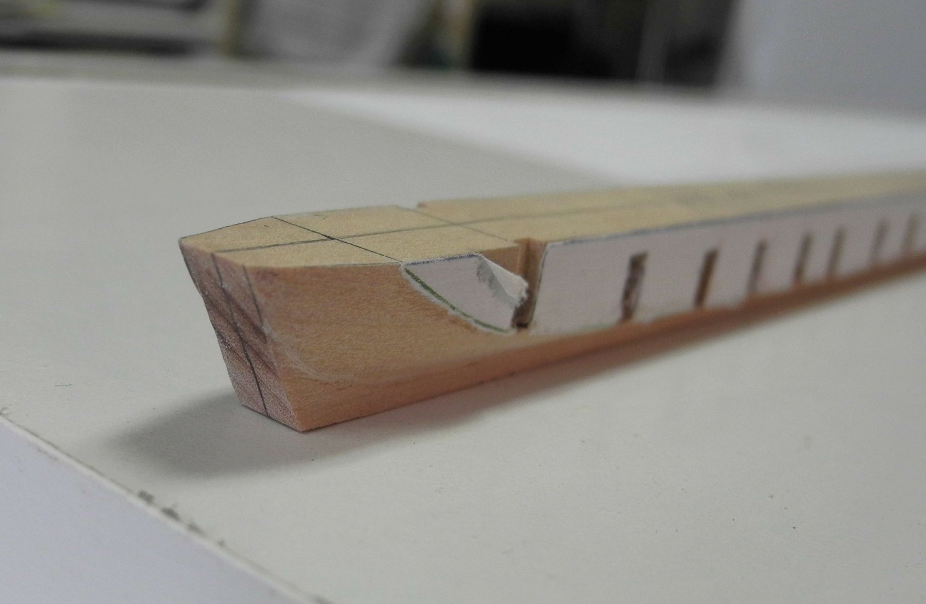
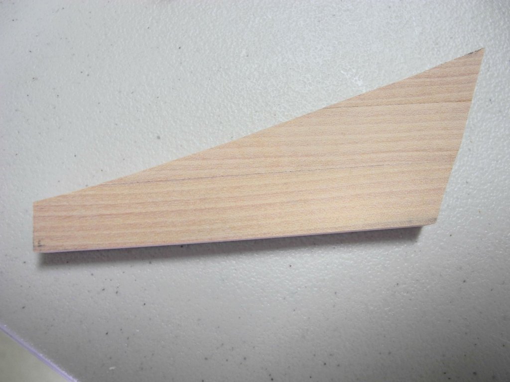
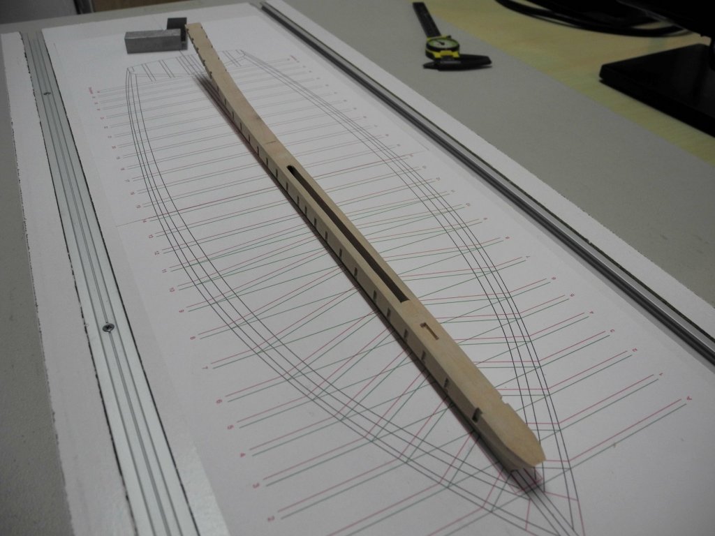
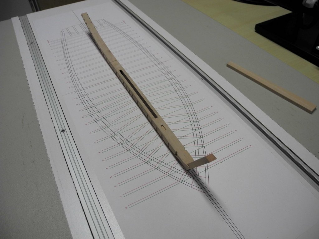
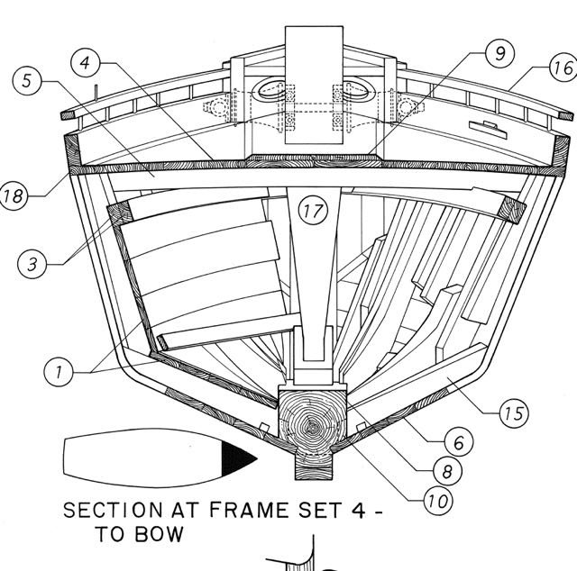
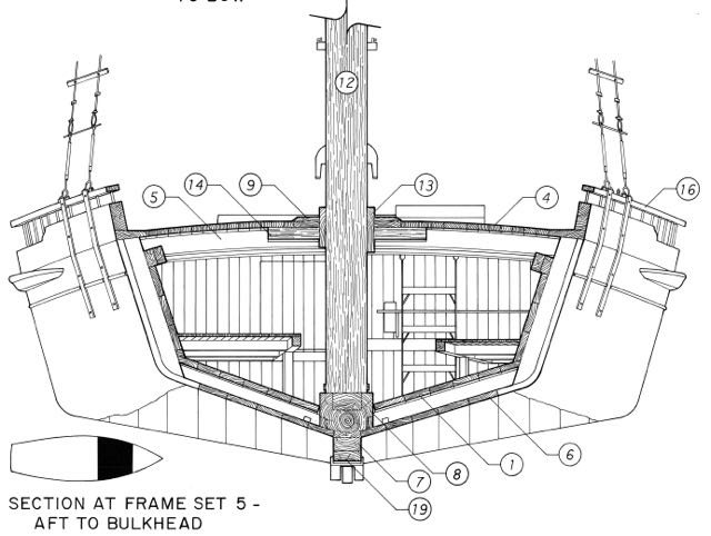
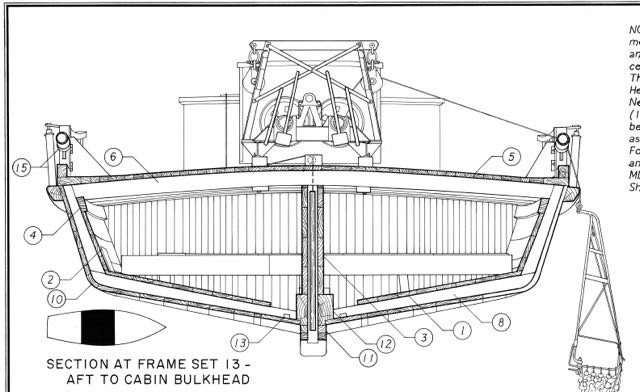
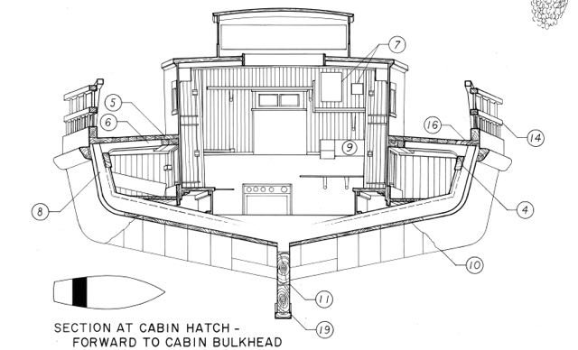
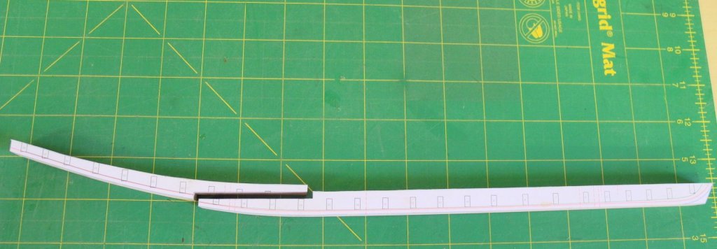
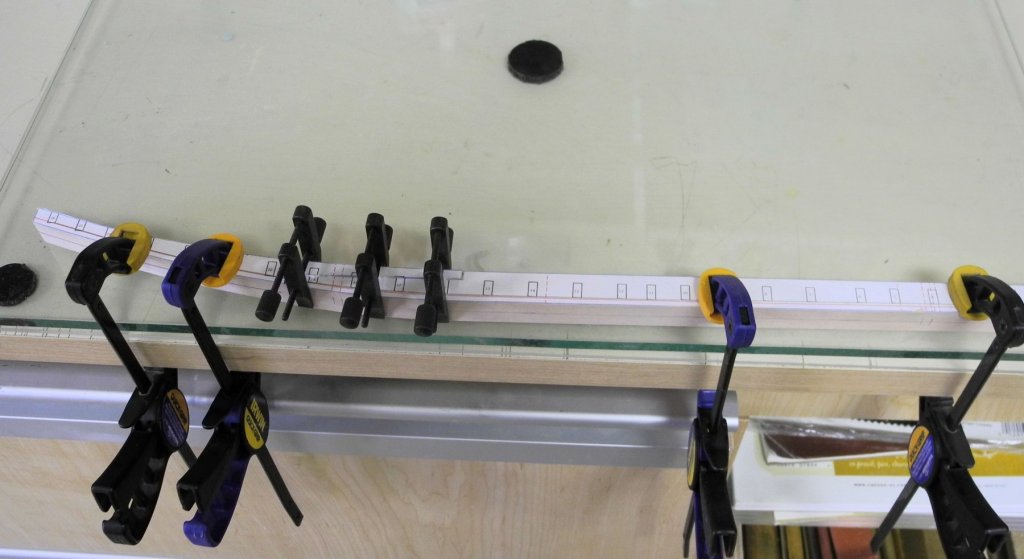
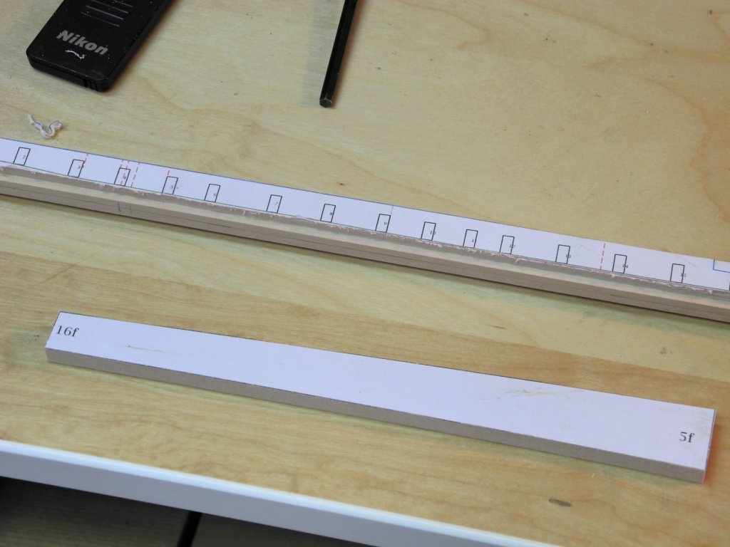
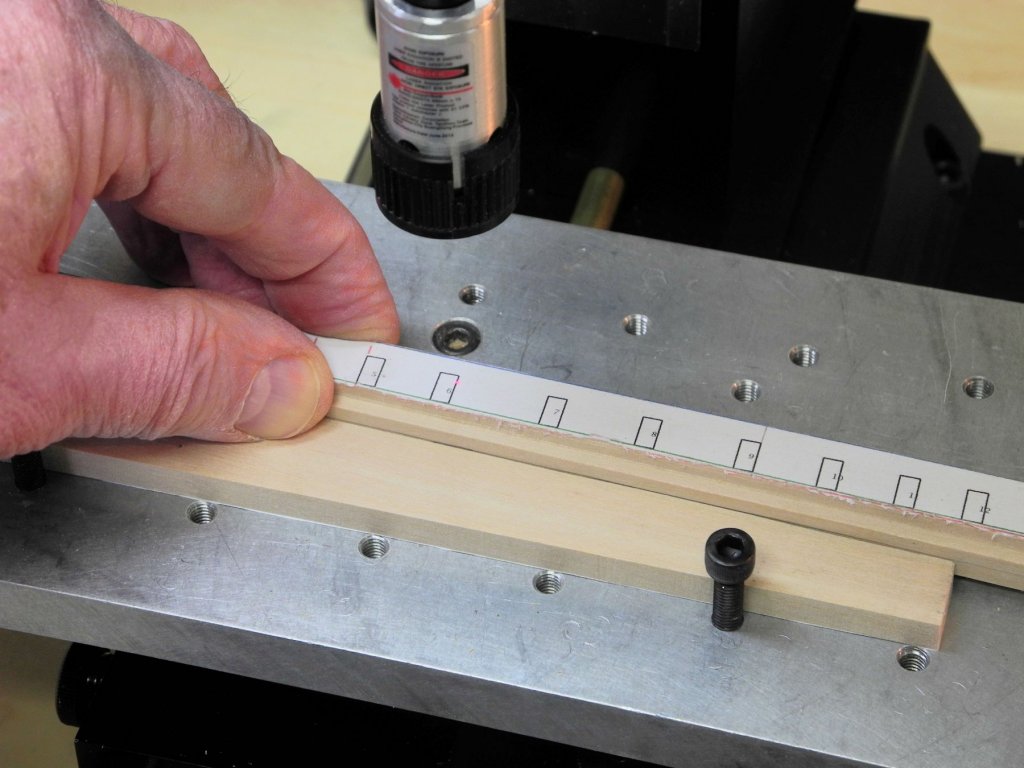
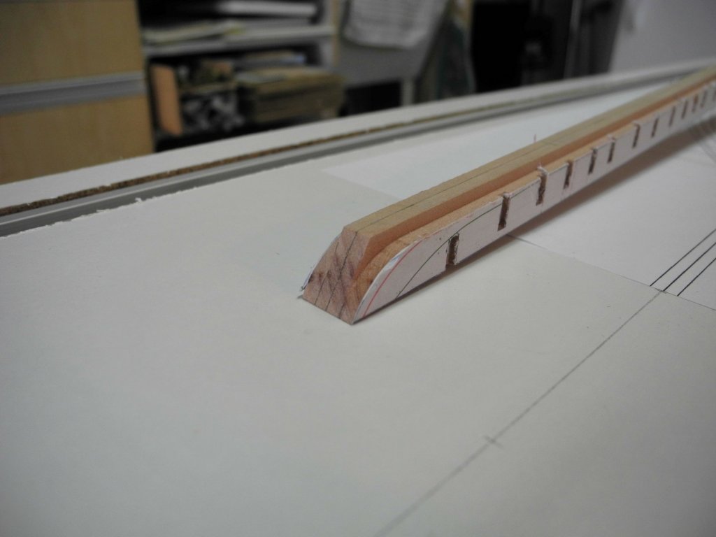
Part 3 – The Keelson After a lot of time spent researching Kathryn and drawing the plans needed to start the build – it’s finally time to make some wood dust! Kathryn’s keelson is a massive timber, consisting of two parts secured by a scarf joint. The individual frames are mortised into the keelson, and a slot for the centerboard runs down the middle of the keelson. The keelson is 16” wide and the height varies, decreasing towards the aft of the boat. The bottom of the keelson below the level of the bottom of the frames is only 8” wide. Following are a few cross-sectional views from the HAER drawings to illustrate the keelson: The first step was to make the two main parts of the keelson. After gluing the drawings of the two parts to the appropriate stock, these parts were cut out and sanded to the lines using the disk sander and the elliptical sander (for any inside curves). These pieces were joined at the scarf and glued, using the clamping arrangement shown. A piece of plate glass was used to ensure that the keelson was straight. The next step was to form the narrow bottom of the keelson. This would be best done on the milling machine, but an approach for cutting along the curve of the keelson was needed. I fabricated a ‘table’ for the milling machine with a peg located in the table. (I saw this in use on another build log – a great idea) By keeping the keelson stock pressed against the peg, it was possible to follow the curve of the keelson with the milling cutter. Light cuts were progressively made on each side of the keelson until the proper depth was reached. The following photo shows the milled bottom of the keelson. The next task was to cut all of the mortises for the frames in the keelson. Since the keelson sits on an angle, a jig was developed to ensure that the frame mortises were perpendicular from the waterline. This jig simply consisted of a piece of wood with the top cut at the appropriate angle. This jig was positioned against two machine screws in the tooling plate to ensure that it was horizontal, and the keelson was clamped against this jig. A laser center-finder was used to check that the mortises would be vertical. The mortises were then cut on both sides of the keelson (the drawing of the keelson was mirrored and pasted to the port side after initial shaping of the keelson). All of the mortises are 2” deep. The ends of the mortises were rounded because of the shape of the milling cutter. These were then squared off using a knife and a small chisel. When reviewing the photos from the recent rebuild, I was able to see that the forward end of the keelson was rounded to the depth of the narrow keelson bottom. A rotary tool with a medium stump cutter was used to form this end of the keelson. The bearding line is very pronounced at the front of the keelson (shown as the dark line bordering the mortises in the above photo). The keelson was shaped to this line, again using the stump cutter. Finally, the forward 12” of the keelson tapers from its 16” width down to 10” – this was done on the disk sander. So the keelson is now fully formed. Next up is to cut the centerboard slot, begin installation of the keel, inner stem, and stem knee. Thanks everyone!


- 878 replies
-
- 31
-
-
On my current build I needed to mill a slot on a curved piece. I saw this idea in a build log a while back - I made a table for the mill with a small a peg in it. By keeping the workpiece pressed against the peg and moving the workpiece towards the cutter I was able to mill the slots I needed. It's best to make a series of light cuts, rather than trying to mill off everything in one pass.


- 146 replies
-
- 13
-
-
Part 2 – Research The HAER documentation contains 8 pages of drawings showing various views of Kathryn, including many details of the interior construction. Since I plan to build the model as a true plank-on-frame with all (or most) interior fittings, these drawings are an excellent resource. Besides depicting the construction details these drawings also contain descriptions and measurements of many of the details. However, I found during the drafting work that these drawings have a few errors – I’ll cover that in a later post. The HAER documentation also includes the detailed description of Kathryn that was submitted for the National Historic Landmark nomination, and this description is a very valuable supplement to the HAER drawings. The HAER drawings are available as TIFF files (much better details than JPG), which were loaded into my CAD program and then scaled to actual dimensions. Each drawing contained a scale that made this easy to do. Where the documentation did not contain measurements for a component, it was usually easy to determine the measurements based on the scaled drawings. I collected the measurements in a separate document for easy reference. That document is attached. Kathryn Specifications and Dimensions.pdf In addition to the HAER documentation the article by Ben Lankford, found in the Nautical Research Journal published in June 1983, contains many useful descriptions and also a table comparing the sizes of different components from various sized Skipjacks. Kathryn is a large Skipjack, and in some cases it was possible to estimate the size of a component by comparing it to the size of the same component in the various smaller Skipjacks. Attached is a PDF of the comparison table. Skipjack Size Comparisons.pdf Photos of the recent reconstruction efforts are available online, and these were invaluable for determining the configuration of several components. Photos can be found at SavingWhatMatters.com, and at the Washington University web site at www.washcoll.edu/live/galleries/2508-restoring-skipjack-kathryn There is also an interesting video on YouTube showing the Kathryn dredging for oysters (the video was taken before the recent rebuild). https://www.youtube.com/watch?v=6FAkIEcLZtA In addition to the above resources, the following books contributed needed information: American Small Sailing Craft, by Howard Chapelle Notes on Chesapeake Bay Skipjacks, by Howard Chapelle Chesapeake Bay Sailing Craft, by Robert H. Burgess Working Skipjacks of Deal Island, by Brice N. Stump I also have a couple of good friends who live in the Chesapeake Bay area, are very knowledgeable about bay craft in general, and who are excellent modelers who focus on the boats of the Bay area. Through these good friends I have been able to go aboard Kathryn after her recent rebuild and have also been introduced to individuals who were instrumental in the rebuild efforts.
- 878 replies
-
- 14
-
-
I finally started building Kathryn. The link is under my signature.
- 649 replies
-
- 5
-
-
- dunbrody
- famine ship
- (and 2 more)
-
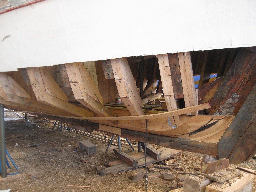
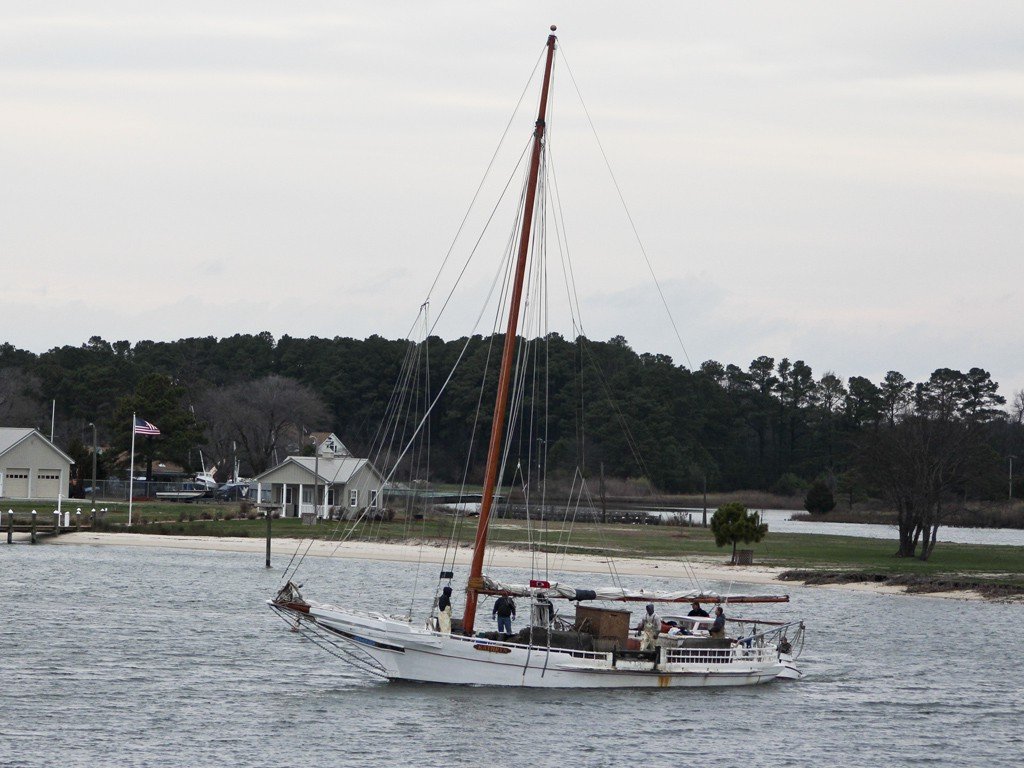
Skipjack Kathryn Part 1 – Background I’ve always liked the lines of the Skipjack oyster dredging craft from the Chesapeake Bay. A couple of years ago I found drawings of the Skipjack Kathryn on the HAER website, and thought this would be an interesting build. Kathryn was built at Crisfield, Maryland in 1901. Kathryn is fairly large for a Skipjack, measuring 50 feet long and 16 feet 8 inches wide. The HAER documentation includes the information that was provided for the nomination of Kathryn as a National Historic Landmark, and indicates that Kathryn is the oldest of the true “skipjacks” - the two-sail bateau built expressly for the oyster trade. Kathryn’s hull is a modification of the standard hard chine skipjack design. The hull has the same general form as the standard skipjack with a sharp convex bow, beamy midsection, and counter stern. The difference is that Kathryn is planked fore-and-aft with a rounded chine rather than having a hard chine and being planked athwartships in a herring-bone pattern. Only a small number of skipjacks have been identified with the same construction – the Susan May (1901) and Maggie Lee (1903) among them. Kathryn carries the traditional Chesapeake longhead or clipper bow with a straight raking stem. Kathryn underwent a major rebuild in 1954, which included the deck and siding, but retained her original form and many of her original oak timbers. The HAER documentation was recorded as Kathryn existed in 1995. Some modifications had been made to Kathryn’s outward appearance, mainly the addition of a ‘doghouse’ or companionway above the main cabin, and the replacement of the forepeak hatch with one of a lower profile. In 2011 Kathryn struck a buoy during the annual skipjack race off Deal Island, Maryland. “Stoney” Whitelock, the current owner and captain, said “When I hit that buoy, that was no big deal, but I found out there was no nails holding the planks onto some of the frames, they were eaten away. Almost all of the frames at some point were rotten.” A major construction project was launched to rebuild Kathryn, starting in 2011 under the guidance of Mike Vlahovich – a master shipwright and founding director of the Coastal Heritage Alliance. The project was funded through grants and private donations, and much of the reconstruction work was performed by volunteers. Kathryn was relaunched during the end of September 2015, and worked the 2015 oyster season. I was able to spend a short time on board Kathryn during October 2015 as she was docked at Deal Island before the oystering season.
- 878 replies
-
- 25
-
-
Good work, Rich. It's better to find the problem early, so that it's easier to fix it. You're moving right along - looking forward to seeing the Argus in a few weeks.
- 1,135 replies
-
- 3
-
-
- model shipways
- syren
- (and 2 more)
-
I just received a copy of “Working Skipjacks of Deal Island” by Brice N. Stump. The author was a long-term staff member at The Daily Times in Salisbury, MD., and has won numerous awards for his writing and photography. This 350 page book is loaded with over 625 black and white photographs, each with a detailed caption. Most of the photos show the Chesapeake watermen at work, and give you an appreciation of how hard they work in the oystering trade. The book contains a good deal of historic information, anecdotes, and explanations of the work involved. I’m particularly interested in the Skipjack Kathryn, and was pleased with the number and quality of the photos of Kathryn. There are over 70 pages dedicated to Kathryn, and each page has a minimum of two photos and related captions. Some of the photos show the recent rebuilding of Kathryn, while the majority show the vessel and crew at work. There are some really interesting photos of the pushboat in use to maneuver Kathryn. Other skipjacks shown in the book include the City of Crisfield, Somerset, Fannie L. Dougherty, Helen Virginia, Ladie Katie, Curlew III, and Ada Fears. I would recommend this book to anyone interested in Skipjacks or the oystermen of the Chesapeake. Priced at $56, it’s a limited press run and available at MyShoreHistory.com

-
SS Mariefred by captainbob - 1:96
Mahuna replied to captainbob's topic in - Build logs for subjects built 1901 - Present Day
Hi Bob: I'm pulling up a front row seat, and I guess I'll be coming to see this new build sometime soon.