


realworkingsailor
-
Posts
3,249 -
Joined
-
Last visited
Content Type
Profiles
Forums
Gallery
Events
Everything posted by realworkingsailor
-
 Probably the captain’s cabin and radio operator’s cabin shared the small structure below the wheelhouse, on the forward end of the boat deck. I’ll check my model when I get home, but pretty sure the coal bunker hatch was located between this part of the superstructure and the funnel. It would be hard to see as there is no coaming. Aft of the funnel is the engine room skylight. Andy
 -
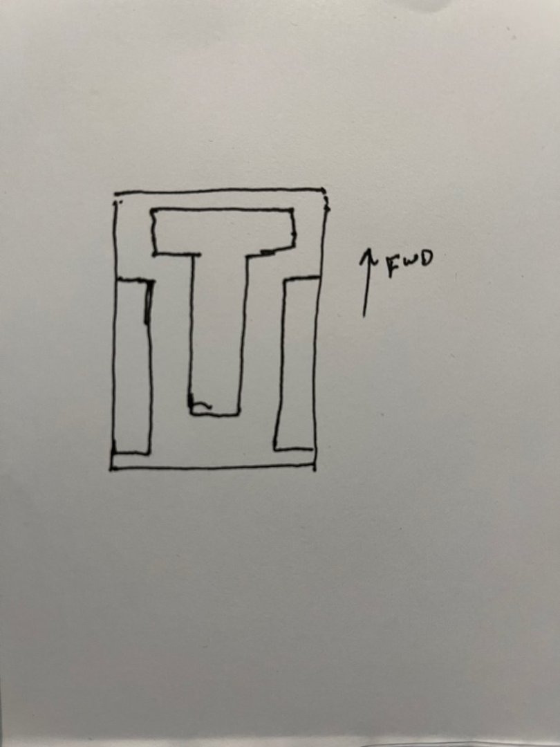
Hi Nils, Looks great! I have a few observations, you can do with them as you will. 😁 The upper deck layout on my model is a little different than what you’ve got. It looks more like this: The “T” structure incorporates the officers’ cabins in the forward part with the balance down the middle being the upper engine room casing. The two long “galleries” also comprise cabins opening inwards onto the covered passageways. They are also flush with the ship’s sides. I’m also wondering about your winch locations. As you’ve got them, the platforms obstruct the #2 and #3 hatch openings considerably, also the layout you have forward would put all the running lines across the hatches as well. Your poor crew and stevedores would be cursing for every pallet they’d have to lift! 😜 I would try to fit the forward winches in the area between #1 and #2 hatches, athwartships at the base of the foremast. If you rebuild your superstructure closer to my rough diagram, it might also give you some room to pivot your after winches clear of the #3 hatch. Again, these are just my own observations, feel free to ignore them as you see fit. Keep up the good work, Andy
-
Have you tried any of Hunterline’s weathering mixes? https://hunterline.com They’re available various shades, made with a rubbing alcohol base. Frequently used in the model railway community for structures and the like. I believe it is also available through MicroMark. Andy
-
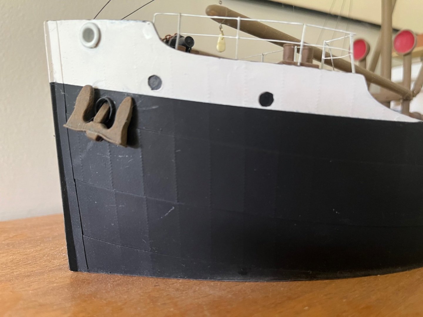
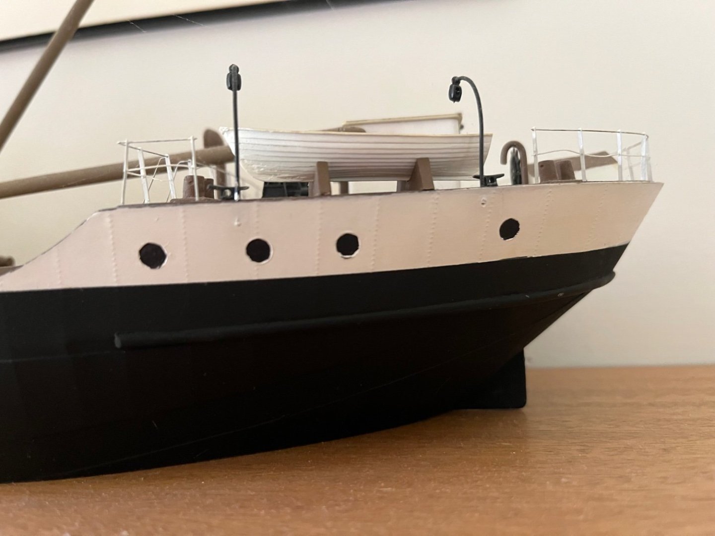
Looks great Nils! I’m sorry I couldn’t show you these earlier, but I have some photos of the Sylvan Scale Models kit that shows the porthole arrangements: They’re cast into the hull and crudely painted in (I started on this kit many, many years ago) Andy
-
You should try talking to @RGL, he’s built/completed a fair number of plastic ships (and other models) with heaps of PE, resin and other aftermarket upgrades. I’m sure he’d be willing to share some insights into his processes. Have a search for some of his build logs on here (there are many). Andy
-
Not as much as you might think. The effective range of a ship’s rudder is somewhere in the nature of 30 to 35 degrees port or starboard. Any further and the rudder begins to act as a brake, and any gains in turning speed is offset by more dramatic losses in forward movement, a critical factor in turning a square rigged ship to be able to miss getting caught in stays. Andy
- 991 replies
-
- 11
-

-
I dunno, given that this appears to be a ship designed for a specific task/roll, (get a lot of guns into shallow waters, close to shore), it’s quite possible that some of the conventions that we’re familiar with don’t apply. Just my observation. Andy
-
I tried to find images to compare, all I found were some ones from an Australian hobby shop: https://au.super-hobby.com/products/F4F-4-Wildcat-53784814.html Although it’s a different paint scheme, it doesn’t look too far different from your own. I’d say you’re doing very well (amazingly well) with what you’ve got. Andy
-
So…. For your next card airplane build you’ll be doing something with an in-line engine? 😜 Looks good (and very tedious)! Andy
- 150 replies
-
- 12
-
-
Good ol’ Pursey’s! Yes I agree some early steel ships did have bar keels, but from what I understand, by the time period of WW1 lake ships had long abandoned that design in favour of internal keel girders (duct keels). A keel hanging down below the hull reduces the amount of “useful” draft a ship can have, ie you carry more cargo if your 25’ draft is all ship, rather that if 6” of that was bar keel hanging down below the bottom. A significant amount of what we would call “modern” steel ship construction was developed on the lakes (the bulk carrier, for example). The lakes have long been about maximizing the ship size to fit a given space. Yeah, the centre line keel. Generally speaking, if you took a transverse section of your ship and drew a square around it, where the bottom of the square lined up with the flat bottom of the ship, and the sides lined up with the vertical section of the extreme breadth, the bilge keels should fit in the triangular section formed by the sides and bottom of the square and the rounded turn of the bilge. Andy
-
Looks good Nils! Before you get too far ahead, you should sand the bar keel down the centre line flat. I think I read you based your build on plans for the wooden version of these ships, which had the old style keel, but that shouldn’t feature on this sort of steel ship. Andy
-
Yup: https://www.sunwardhobbies.ca/revell-eurofighter-typhoon-black-jack-1-48-scale-rvg-03820/ Andy
-
I looked on Scalemates and couldn’t see anything amongst the listed AM sets. Could you scratch build the fishplates from thin brass or styrene stock? Andy
-
Nice! Do you know his plane(s) number/code? The 1/72 Airfix kit that I’m building comes with markings for 404 squadron. (EE-F). My build is on a bit of a summer stall at the moment, but I’ll pick things up when the weather starts to cool again. Andy
-
I’m in! That’s quite the collection of extras that you’ve amassed! Looking forward to watching your progress at whatever speed you comfortably attain! Andy
-
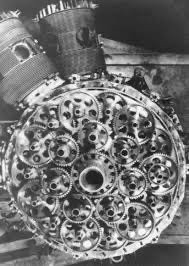
Just for fun, here’s the sleeve valve timing gear train of a Bristol Hercules engine: It looks a little insane at first glance, but if you take your time and pick through the gears, it does begin to make sense. Andy
-
Yep! We just took slightly different roads to get there 😁 Andy
-
There was a little government assisted industrial espionage. From what I understand, the Air Ministry passed on quite a bit of the Napier’s technological information along to RR… The sleeve valve came about after a 1927 paper by Harry Ricardo that calculated a maximum HP limit for poppet valve engines. (Not sure if that was for single or multi valve engines, the prevalence today of DOHC multi-valve car engines might suggest only the former). The sleeve valve was a workaround that allowed greater optimal airflow, thus bypassing the theoretical HP limitation. Ultimately, as you say a turbine engine will always outperform a comparable reciprocating engine. Partly due to fluid and thermal dynamics, but also due to the energy, and therefore efficiency, loss caused by converting reciprocating motion to rotary motion. I think it’s more fair to think in terms of relative efficiency, rather than absolute, and the Sabre delivered in spades. Andy
-
Look up Rolls Royce Eagle 😉 Andy
-
Not arguing that technology leapt ahead during the war and that jet propulsion far outclassed anything that piston power could put out. My point was more towards the fact that, when you look at engine development, other engines were further ahead in development by the time war broke out. The RR Merlin was first run in 1933. They had 6 years to work out kinks and improvements before the outbreak of the war. Six uninterrupted years to commit resources and personnel to refine the manufacturing process and develop effective mass production strategies, and even develop potential successors. The Sabre first run in 1938, and at the time Napier was basically a “boutique” manufacturer. All their engines were hand built by craftsmen. They had no experience with mass production on the levels required by war demands. They also had minimal experience with other new technological elements of the Sabre engine, like the sleeve valves. And they had all of a year and a half to figure all these things out before the buzzer went off. Oh, and RR was slagging Napier at the Air Ministry, because they were legitimately afraid of what the Sabre could do. Napier didn’t finally catch a break from the government until Beaverbrook arrived in 1940. Andy
-
Napier was messing around with adding a multi stage turbo to their engine for high altitude performance, unfortunately this came at the detriment of remedying the flaws of the engine. When English Electric bought Napier, they scrapped the turbo project and concentrated on fixing the engine issues (I suspect the British government may have had something to do with the EE takeover, or, at the very least, the removal of red tape to accelerate the process). I suppose if it wasn’t for the necessities of wartime, the real untapped potential of the Sabre could have been unleashed. Andy
-
Thanks Alan! I was vaguely aware that there was something going on with a Typhoon resto, I didn’t know they were actually trying to get it not only airworthy, but with a Sabre engine too, if I catch the gist of your article correctly (repop or resto, doesn’t matter, it would be a thrill just to hear one start up after, what?, sixty something years, @egilman probably knows when the last Sabre engine flew). Andy
-
That planking looks fantastic! I trust that nary a copper tile will ever obscure any of your hard work? Also, I would be remiss if I didn’t say thanks for the “new” word to add to my vocabulary! Andy
- 648 replies
-
- 4
-
-

-
- Indefatigable
- Vanguard Models
- (and 1 more)
-
Hmm… I guess you could try some appropriate diameter styrene rod perhaps? Andy
-
Is it even a part? Are parts 34 b c and d meant to form a hollow tube with part 34 e meant to be a capping piece? Andy


