realworkingsailor
-
Posts
3,271 -
Joined
-
Last visited
Content Type
Profiles
Forums
Gallery
Events
Everything posted by realworkingsailor
-
 So I made it home yesterday afternoon. This morning, while chatting with the manager at the hobby shop, it would seem that the guy behind Sylvan Scale Models would like to see some of my progress! I guess I'm the first person he's heard of to attempt what I'm doing... Cool! As an aside, the Toronto Railway Prototype Modellers annual Meet will be at Humber college on March 15. I'll have my ship down there (provided I'm not back at work, of course). Let me know if you need more information. Andy
- 382 replies
-
- 4
-

-
- stadacona
- sylvan scale models
- (and 1 more)
-
Thanks, Robbyn. Sorry to hear of your difficulties with your Syren build. Hope things work out for you in round two. Andy
- 382 replies
-
- 1
-
-
- stadacona
- sylvan scale models
- (and 1 more)
-
Thanks everyone! I'll be out of town this week on a training course, so there won't be any work in the shipyard, maybe it will give my remaining parts time to show up. Andy
- 382 replies
-
- 1
-
-
- stadacona
- sylvan scale models
- (and 1 more)
-
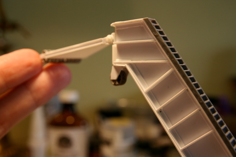
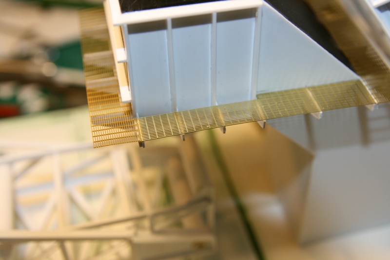
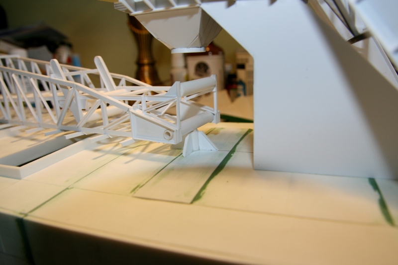
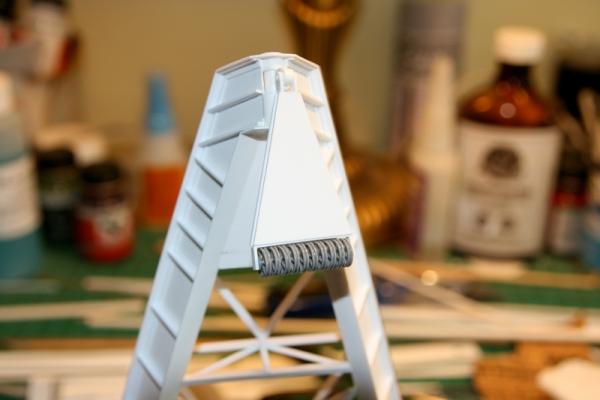
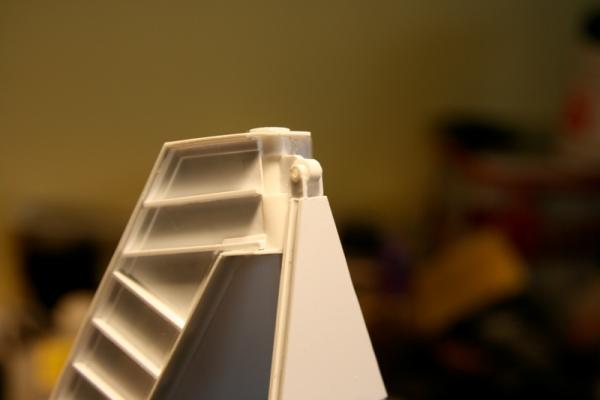
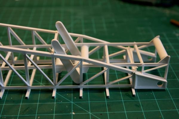
First order of business was block and sheaves that direct the topping lift down to the luffing winch. On closer inspection of photos, it turns out these two sheaves are the same size as the others, so that made things a bit easy. The whole assembly is just an oversized (or undersized depending on your perspective) caster, so assembly was pretty straight forward. You can see the block swivels in conjunction with the headblock to keep everything in allignment. Next up is the replacement mesh. no issues with this stuff. Much better material, and a more realistic pattern to boot. Finally, I've begun work on the boom pedestal. This is the assembly that supports the heel of the boom. Pretty self explanitory. Aside from gluing the pedestal to the deck, everything else is just dry fit for now, to allow removal for painting later on. I did a test run reeving some light thread through the blocks and sheaves... it's going to take a lot of line...... something to work on later when things are painted and fixed in place. Andy


- 382 replies
-
- 14
-
-
- stadacona
- sylvan scale models
- (and 1 more)
-
Good news, some more of my parts have arrived....namely the mesh I needed. It's a lot better than the aluminium mush, and it's a proper slotted mesh, rather than a chicken wire diamond pattern. I'll have some progress photos later today, possibly. Andy
- 382 replies
-
- 2
-
-
- stadacona
- sylvan scale models
- (and 1 more)
-
She'll be fully weathered... Rust, soot, grease, spilled cargo, and all. You've got me there, John.... Maybe you're not made of resin? Andy
- 382 replies
-
- 2
-
-
- stadacona
- sylvan scale models
- (and 1 more)
-
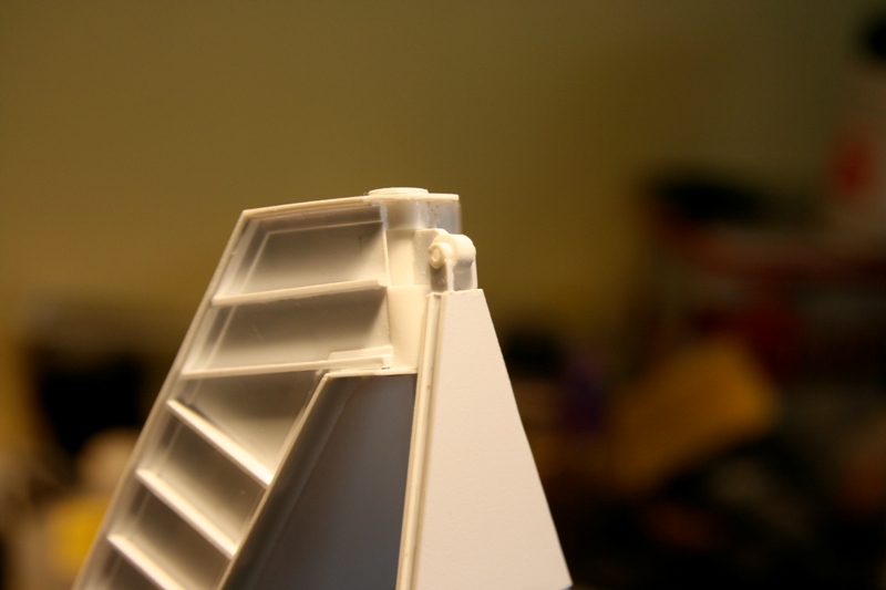
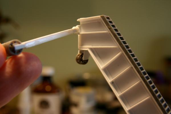
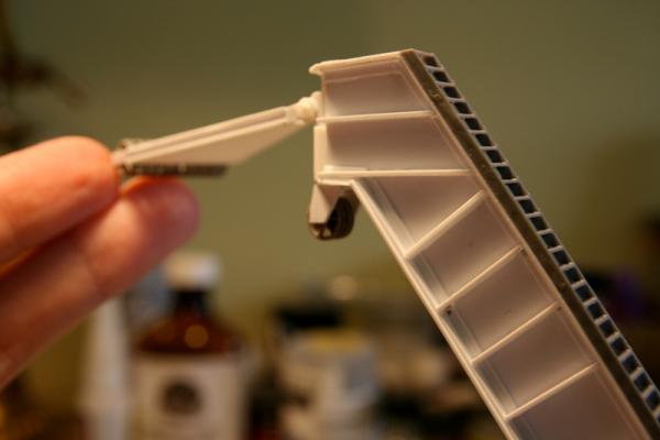
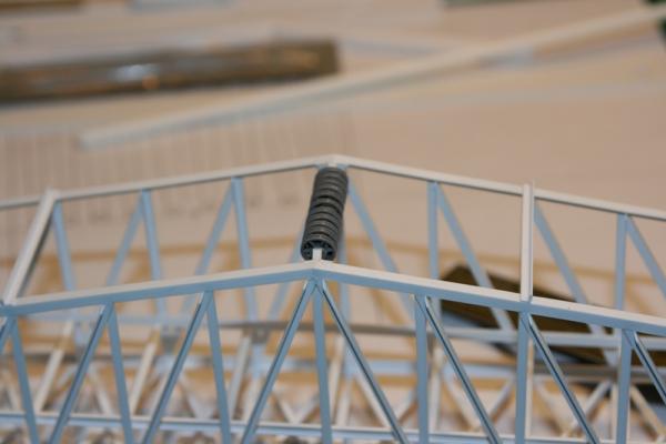
I spent some more time the other day working on the headblock. I've just got a few finishing touches left to do. I also got the gooseneck connection to the head of the A frame pretty much finished. A miracle in that I managed to keep the glue away from the working parts, so it pivots and swings freely in all directions required (the capillary action of Tenax is incredible). Last night I also got the first three rollers from my friend. He's done an amazing job, they are perfectly identical to the master I gave him, and aside from some expected flash, there are no defects or bubbles. He makes his moulds and sets them in a vaccuum to get rid of any air bubbles. After he pours the resin, he puts the casting under pressure. I've seen some other examples of his work, it's the finest resin casing I've ever seen. Anyway, just that small update for today. The way things are right now, progress is slow. Just the nature of the monster really. Andy

- 382 replies
-
- 21
-
-
- stadacona
- sylvan scale models
- (and 1 more)
-
Waaay back I posted a picture I took of a naval mine: http://modelshipworld.com/index.php?/topic/1375-andys-maritime-adventures-season-ii/page-54 Although this one came from a surface vessel, the principle is the same. Andy
-
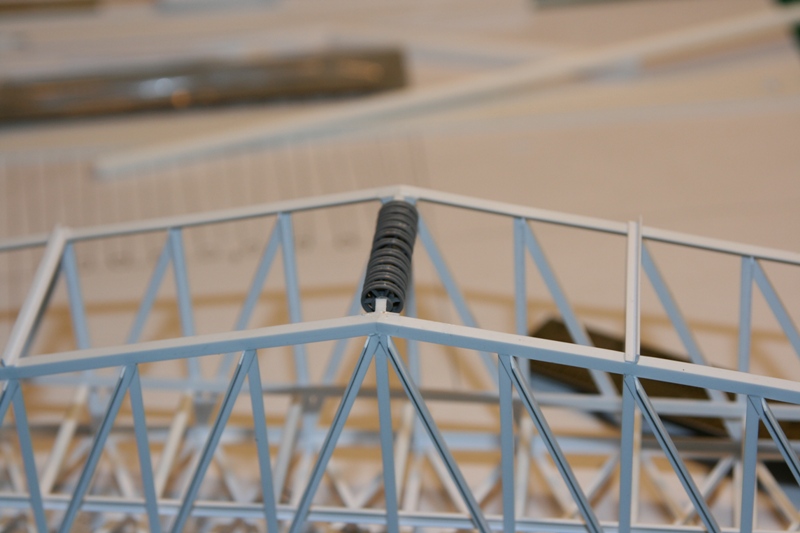
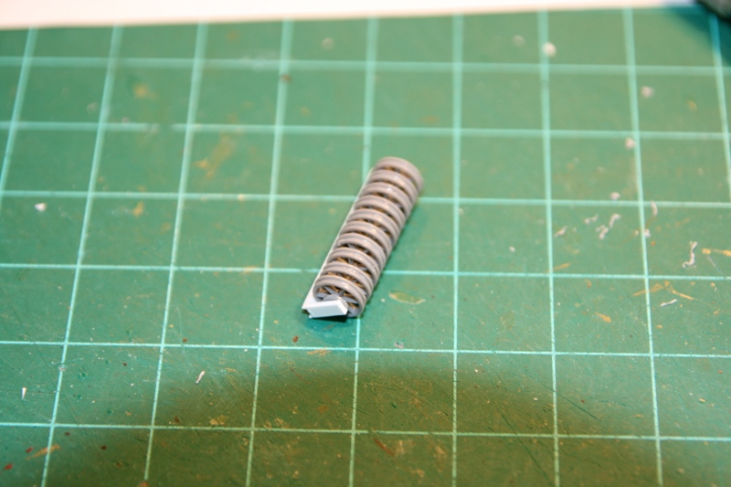
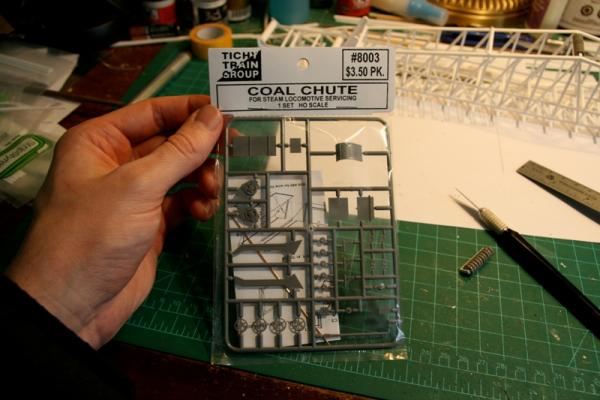
So from Tichy came a small box with a dozen coal chute kits. This may seem a bit odd, but in each kit there are two open spoked pulley sheaves. Exactly the style I was looking for. And there's also a good assortment of other industrial odds and ends that could prove useful later on. I got right to work on assembling the sheaves. I worked out I need 11 sheaves on the boom itself, and 10 on the headblock, at the "A" frame. There is also a block with 2 smaller sheaves, hung below the top of the A frame, that direct the cable down to the luffing winch drums. The sheaves all sit on a phosphor bronze axle, that came with the chute kit. Andy

- 382 replies
-
- 11
-
-
- stadacona
- sylvan scale models
- (and 1 more)
-
A small-ish package was waiting in the mail box the other day. Some of my parts finally arrived! More progress soon. Andy
- 382 replies
-
- 3
-
-
- stadacona
- sylvan scale models
- (and 1 more)
-
Don't worry, I will get back to Pegasus at some point. I think that after almost two years of concentrated effort on her, I needed a bit of a breather. To be honest, I did start tying a few ratlines back in December, but I just couldn't get into it. So rather than doing a botch job, I set her aside for the time being. Andy
- 382 replies
-
- 5
-
-
- stadacona
- sylvan scale models
- (and 1 more)
-
Longevity, really. It's all still up for further discussion, nothing has been decided either way, just opening up options I'd say go for it! Keep building what you enjoy Andy
- 382 replies
-
- 1
-
-
- stadacona
- sylvan scale models
- (and 1 more)
-
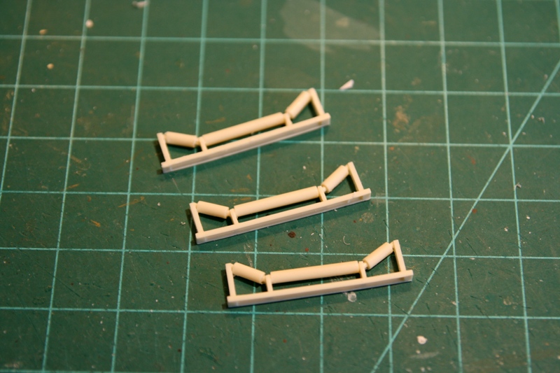
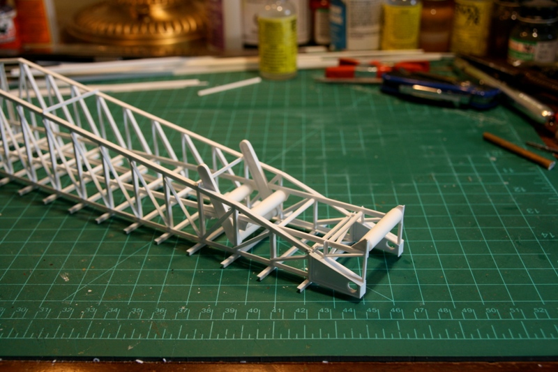
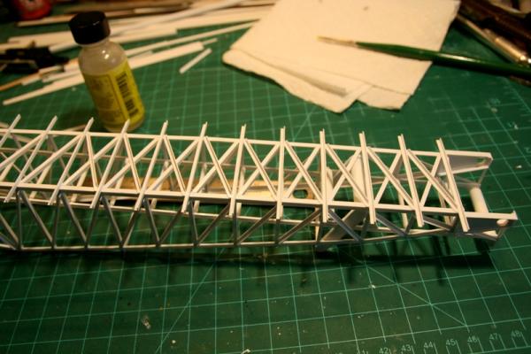
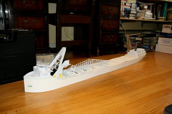
So now that the lower rollers are all in place, I can turn my attention to the cross bracing at the bottom of the boom. Nothing really fancy. I've sent the cradle rollers off to be copied, so hopefully before then end of the month I should have them in hand, and along with my still MIA parts I should be able to get this unloading boom out of the way, and get on to the rest of the detail work about the ship.... oh yeah... and finish the hull.... enough of these dry-fit overall photos. Andy

- 382 replies
-
- 20
-
-
- stadacona
- sylvan scale models
- (and 1 more)
-
Bend cast metal parts
realworkingsailor replied to bogeygolpher's topic in Metal Work, Soldering and Metal Fittings
Heating white metal parts can be risky, as you do risk melting them. In the case of cast decorations, look into making a resin copy. Urethane resin plastic can be easily bent after a quick dip in boiling water, and will cool and harden again, without risk of melting the part. Andy -
Hmm... Another good idea... Thanks Mark! Hi Popeye, thanks for the offer, but I have some scale electric motor castings on order that should arrive any day now Andy
- 382 replies
-
- 1
-
-
- stadacona
- sylvan scale models
- (and 1 more)
-
I know..... I'd have to locate some larger format film.... If it still exists... Same basic idea, just a generation, or so, newer. Andy
-
Dan, unfortunately (or maybe fortunately) it's just going to be static. Trying to get 100+ individual rollers square, true and turning freely is a task I can well do without. At a larger scale, with Michael Mott's machining ability.... I might have considered it...... Maybe...... John, I was originally thinking of using something like construction paper, but I've also begun to think maybe film strip, if I could find some with about 30mm between the perforations (so I could cut the off and still have a belt wide enough)..... Robbyn, yeah.. I'm still here.... Although I'm feeling more like a fringe dweller lately. I'm glad you like my progress to date, but I must admit, she still lacking in a lot of essential details. In due time I'll get there, once I get the unloading gear finished I'll have more time to devote to getting the rest sorted. Andy
- 382 replies
-
- 2
-
-
- stadacona
- sylvan scale models
- (and 1 more)
-
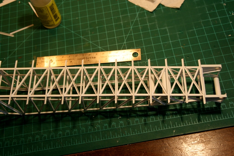
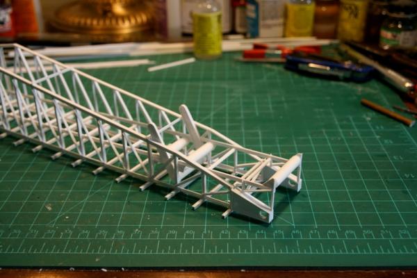
So..... rolling right along... More rollers. Made up the assembly that supported belt under the loop belt hopper. I've also added the heel roller, and drive and tensioning rollers...and a few more small rollers just for good measure. The boom belt drive motors were locaded on a platform atop the boom. You can see where this will be, with the belt chain drive covers protuding up awaiting their respective motors (castings are on order)Aside from some bracing, I'm basically waiting for parts, sheaves, motors, walkway mesh...... maybe next week I might see something arrive..... Andy
- 382 replies
-
- 14
-
-
- stadacona
- sylvan scale models
- (and 1 more)
-
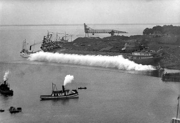
Yup! Launched as Glenmohr, but renamed right after launching. Also the first commercial vessel to transit the current Welland Canal in 1932. Andy
-
Well.. I was thinking to guess the name of that rowing skiff in the bottom centre just off the bow of that steam tug.... But, yeah, the laker will do just fine.
-
As Promised
-
I'd say, just go with whichever makes you happier..... And at the moment, you and pretty much everyone else so far seem to be in favour of the Victory. Andy
- 1,319 replies
-
- 4
-
-
- caldercraft
- Victory
- (and 1 more)
-
I'll have something up tomorrow, 'til then, hang tight Andy
-
HMS Caroline
-
Nice fix, she looks none the worse for wear after her maiden flight.... Andy