realworkingsailor
-
Posts
3,271 -
Joined
-
Last visited
Content Type
Profiles
Forums
Gallery
Events
Everything posted by realworkingsailor
-
 Looks like you've pretty well mastered rattling. Very well done. Andy
- 800 replies
-
- 1
-

-
- snake
- caldercraft
- (and 1 more)
-
Very nice planking job! I'd be hesitant to want to cover that up entirely with paint. A light wash or stain would look excellent, if only to mute some of the colour variance of the planking. Andy
- 2,191 replies
-
- 1
-
-
- confederacy
- Model Shipways
- (and 1 more)
-
Hey Popeye, you're getting a bit hard to follow, and I've been a bit remiss in commenting on your progress on your various builds. Just to let you know, I am trying to follow as best I can, and you're doing a great job. Andy
-
Another trick you might want to try; after applying proper masking tape (like Tamyia) spray with a coat of Dullcote to seal the edges. This will help eleminate paint bleed. Also make sure that the masking tape is firmly stuck to the ship, run a rounded dowel, or the back of your fingernail along the tape edge to press the tape adhesive to the model. Andy
- 47 replies
-
- 5
-
-
- constitution
- revell
- (and 1 more)
-
Uh oh... Looks like the man in the knitted woollen (at least thats what it looks like to me... if I'm wrong, perhaps he should ease up on the doughnuts), sweater is about to be put to work... Andy
-
Good night Irene! (Ok, sorry, just had to say it ) A very nice job, Peter, can't wait to see her masted, rigged and under sail. Andy
-
Very nice, Grant! I'm not sure, but can you start to see the finish line yet? You've got to be almost to the final turn by now.... Andy
-
Yessir! Have at it! Andy
-
Well, you do indeed have the correct location
-
Still working on hatches, and waiting for parts. Nothing really photogenic at the moment. Hopefully sometime over the next week something may show up..... Andy
- 382 replies
-
- 3
-
-
- stadacona
- sylvan scale models
- (and 1 more)
-
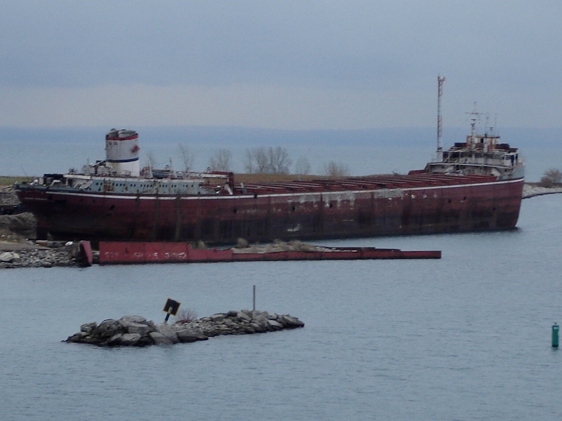
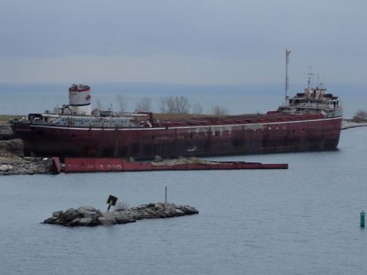
Here we go, a scrap laker... (Just for Jan )
-
Yeah, ok... When the time comes, I'm stealing your method.... Looks really good Andy
- 1,279 replies
-
- 1
-
-
- agamemnon
- caldercraft
- (and 1 more)
-
I'm still looking for something... Hang in there Andy
-
HMS or HMCS Warrior Andy
-
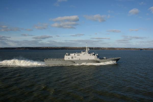
It's the USS Freedom, on her delivery voyage. She did a tour of the great lakes. I took that photo as she overtook us in the St Lawrence River near Cap St Charles. She threw such a wake that we started rolling. Incidentally, I did encounter her earlier on Lake Erie and had her plotted on radar doing in excess of 40 knots.... Andy
-
Eventually, yes, but for now they can't be installed.......for their own protection. Andy
- 382 replies
-
- 3
-
-
- stadacona
- sylvan scale models
- (and 1 more)
-
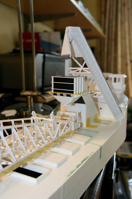
The hatches on the Stadacona are (were) manual telescoping covers. A step up from wooden board/wedge/tarp covers. The top most covers sit closest to midship, with the succeeding covers progressing outboard. When I get to glueing on the open covers, it will all make sense. Andy
- 382 replies
-
- 2
-
-
- stadacona
- sylvan scale models
- (and 1 more)
-
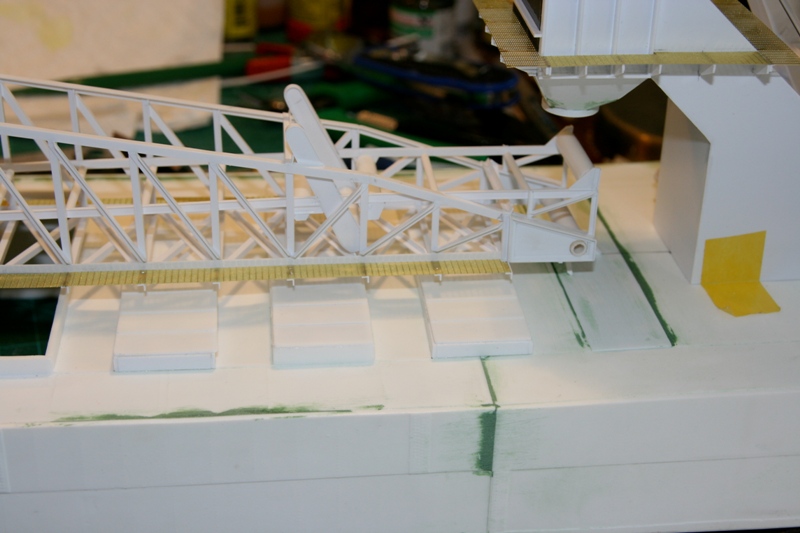
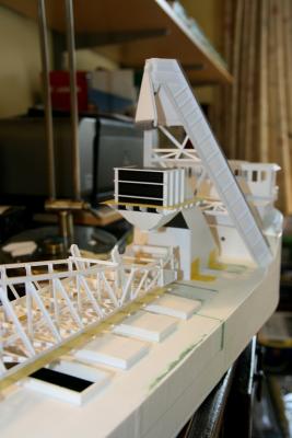
Alright, time for some progress.... Been playing with that nice metal walkway again. I've now got both walkways along the boom installed. All handrails will be applied just before painting as they are fragile and tend to get in the way. As I am once again waiting on parts, I've also started work on the extra hatches. The first and third are the add-ons, the second and fourth are original. I do intend to leave quite a few open to view the cargo inside, but the first 3 and all the added ones will be closed. The kit provides more than enough covers in both positions, so I'm not worried about running out of hatches.... yet... Andy

- 382 replies
-
- 17
-
-
- stadacona
- sylvan scale models
- (and 1 more)
-
Don't think this one will be too hard.... Have fun. Andy
-
Still looking for something... Please hang in there Andy
-
Well... Even from the thumbnail photo, the markings were distinctly American (kind of the idea of aircraft markings, don't you think? )... After that simply looked up a list of US carriers and sort through until I found a match. I'll have something tomorrow afternoon. Andy
-
USS Independance (CVL 22) Aircraft markings kind of made that one a give away... Andy
-
Rigging looks fantastic! Sorry to hear of the other issues. Hope the reno goes ok. Andy
- 1,279 replies
-
- 1
-
-
- agamemnon
- caldercraft
- (and 1 more)