modeller_masa
-
Posts
927 -
Joined
-
Last visited
Content Type
Profiles
Forums
Gallery
Events
Everything posted by modeller_masa
-
Congratulation! Very nice painting and educational build log. I bought the same kit and will try again next year. Merry christmas and happy new year~
- 38 replies
-
- 1
-

-
- Model Shipways
- Shipwright Series
- (and 2 more)
-
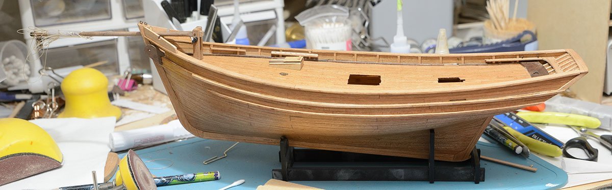
Thanks for your comment, Yves. I'm sorry about the long vacation. I have experienced long hiccups while dancing on inaccurate references. Due to my high expectations, I referred to some internet manuals from Billing boats (BB580) and AL (22175 newer kit). Also, I checked videos of the real thonier on Youtube. They were confusing because they had only a fewer intersections. I was struggling between the three manuals and videos to build the best thonier. I finally found the most reliable source, such as the AAMM monograph. * More reliable reference list https://boutique.aamm.fr/plan-thonier-marie-jeanne https://planeteloisirs-bg.fr/index_fichiers/pages/bateau/marie-jeanne-1.html https://www.amazon.com/dp/2213003858 If you want to build a better thonier than any consumer kit, I recommend buying the AAMM monograph. Unfortunately, it is too late to buy the book because I want to wrap up this project this year. 😂
- 17 replies
-
- 3
-
-
- Marie-Jeanne
- Artesania Latina
- (and 1 more)
-
If you haven't resolved the issue yet, I recommend resetting the browser app. Go to the control panel and uninstall the browser. Otherwise, you can see a "user data reset" or similar button. Once you reset the browser app, you should go to Google Play and update it to the newest version. Also, your favorite webpage list will be removed. If you want to keep browser info, backup the favorite list before resetting.
-
https://www.keranova.es/categoria-producto/modelismo-naval/?product_brand=5638 Have you ever heard about the company? It looks like a new company in Spain. https://www.scalemates.com/kits/keranova-51201-pilar--1494376 This is the most expensive kit from the company. New companies and kits are always welcome. By the way, Carthago Nova is a historic city in Spain. https://www.worldhistory.org/Carthago_Nova/
- 1 reply
-
- 3
-
-
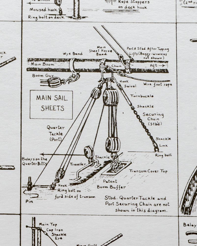
Help for blocks with hoop required.
modeller_masa replied to Tony28's topic in Masting, rigging and sails
I guess you are making Bluenose from Amati. This book may help your understanding. https://www.amatimodel.com/en/models-amati-classic/product-bluenose-b1447.html These are examples by Amati.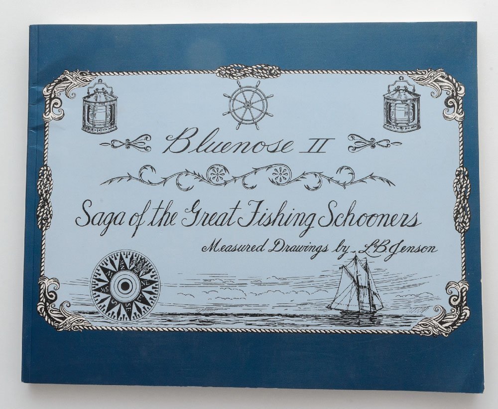

-
The silkspan is the brand marketing name of an original paper that was invented in China in the B.C. 50s. The modern paper we use every day is refined by machine and chemicals. The old and original paper have low density and higher tensile strength. The original paper is so popular in the East Asia region. Asians use the original paper for many purpose, such as windows and wallpaper. I can find and buy the silkspan paper at every stationery shop in South Korea. The original paper has different name by country. - Chinese paper in China, Korean paper in Korea, Japanese paper in Japan, or Japanese rice paper, etcs. Wefalck introduced industrially refined original paper made by a German company. The refined paper is optimized for the model project; longer fibers and evenly patterns. I guess it is hard to find the original paper in the Western region, The different names may help you find the "Silkspan". (When I saw the word first, I purchased "silk and span fabric," literally. 😆 )
-
Light table question
modeller_masa replied to GrandpaPhil's topic in Modeling tools and Workshop Equipment
Lamp = LED strip Diffusion plate = Laser engraved acrylic panel https://en.kohacraft.com/archives/make-a-flat-light-emitting-lighting-by-processing-acrylic-into-a-light-guide-plate-with-a-laser-cutter.html https://aliexpress.com/item/1005006156384485.html Diffusion film = translucent PET film https://aliexpress.com/item/1005006059186279.html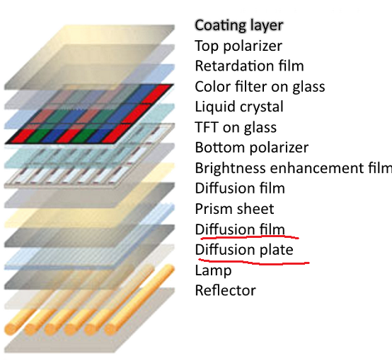
-
Light table question
modeller_masa replied to GrandpaPhil's topic in Modeling tools and Workshop Equipment
Technically, the best light diffuser panel is the part in the LCD screen for TVs and smartphones. There is a thin LED light strip at the bottom of the display, and the thin layer emits and spreads light to the entire screen equally. It seems like the light pad has a similar structure. The video shows how he modified a monitor into a light pad. https://aliexpress.com/item/1005004799141286.html I'll try this diffuser film. -
Light table question
modeller_masa replied to GrandpaPhil's topic in Modeling tools and Workshop Equipment
I'm not sure my design will work, but I like the light table idea.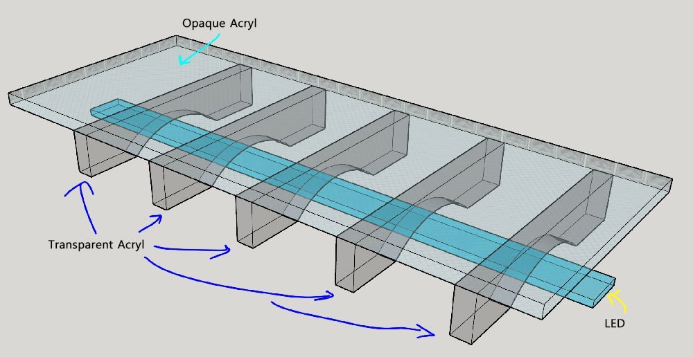
-
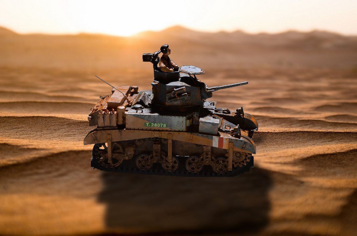
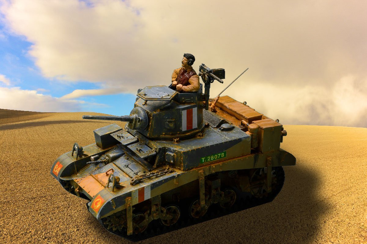
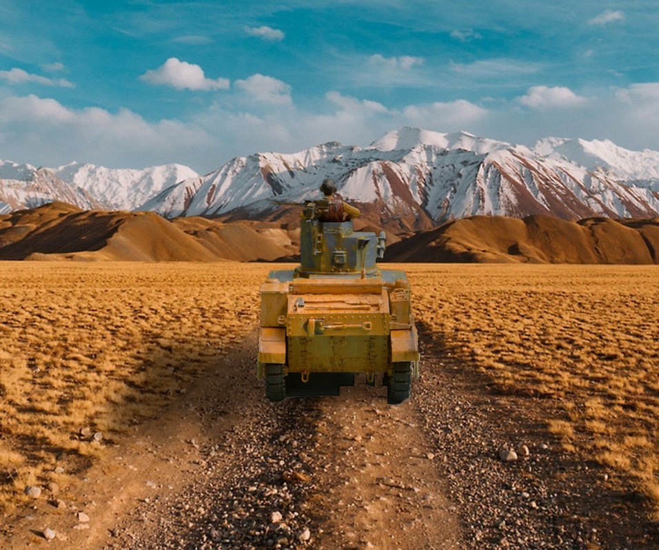
I made the Academy M3 Stuart "Honey" kit during a weekend. I also tried Chroma Key method with photoshop. The manual chroma key is really time consuming and inconvenient. I would like to purchase a paid plugin... Thank you for enjoying my pictures.
- 2 replies
-
- 12
-
-

-
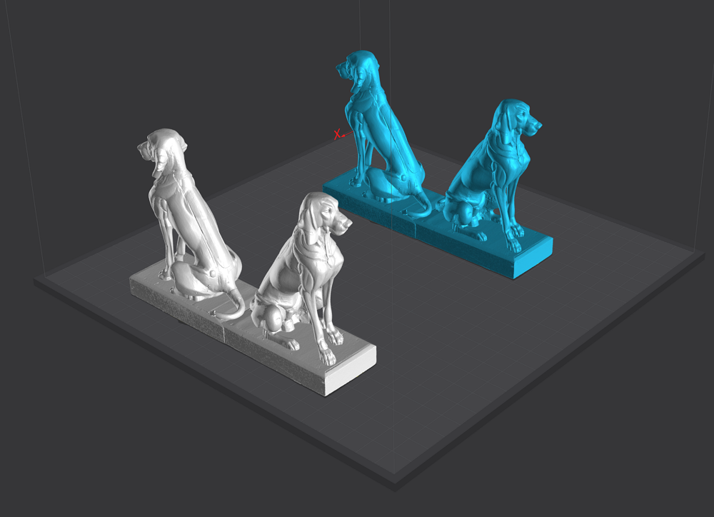
Wow! The viking ship is really impressive! I thought that 4 beagle dog figures support the hull.

-
Thanks for the nice explanation, Henry. I'm considering building HMS Beagle. I may need to build a custom animal figure with Zbrush.
-
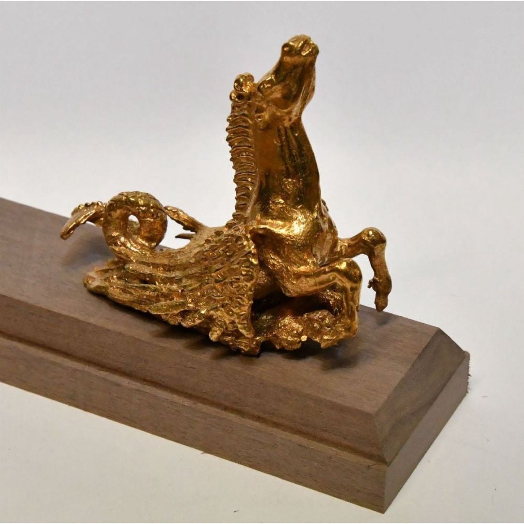
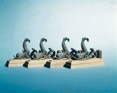
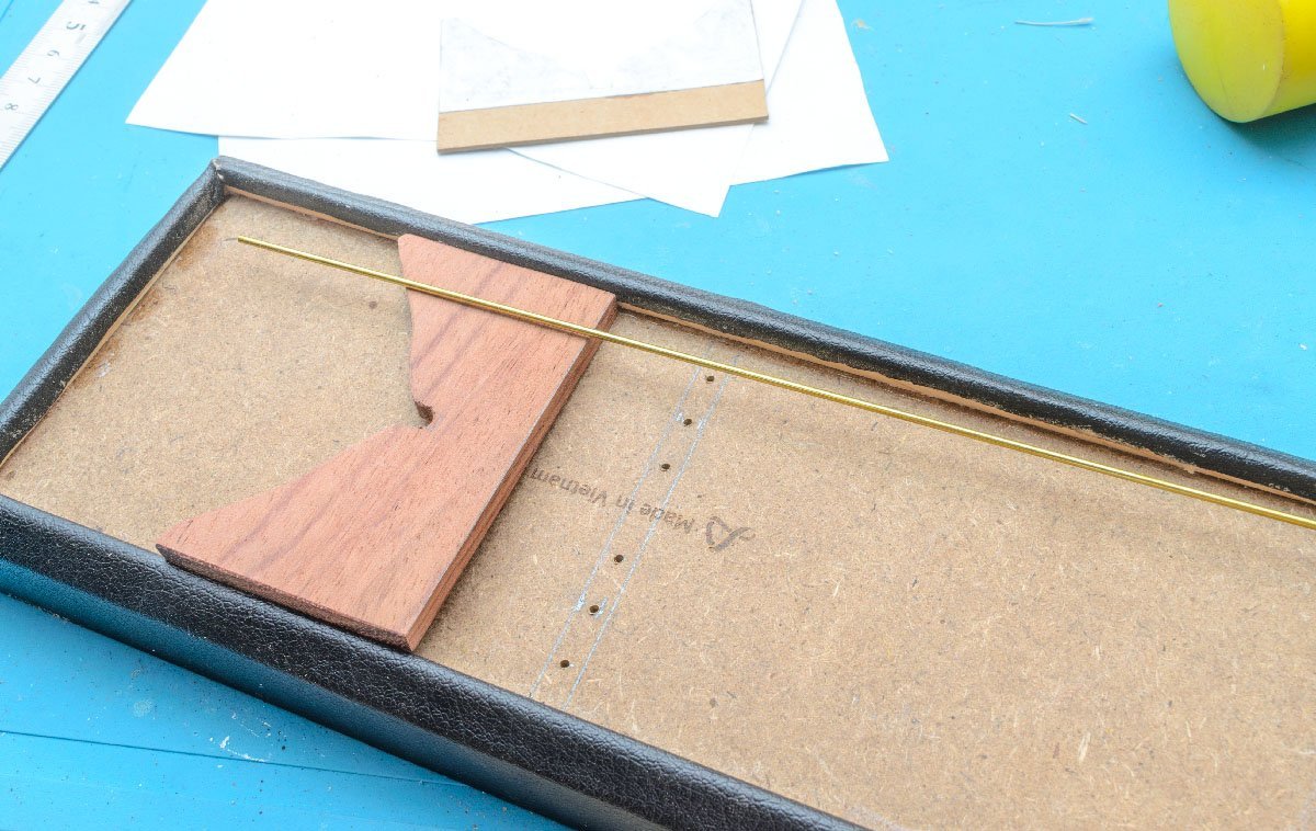
(Mantua's display base) I have a small question. I saw some products for the display base, but I don't understand how model ships are mounted on it. I'll print some 3D figures and use them as display bases. Do I need 4 figures to mount a model ship properly?
-
Thank you so much, Baker. Although It's not as good as I expected, I wish to improve next time with your kind comment. Thanks, Jeff.
- 13 replies
-
- 1
-
-
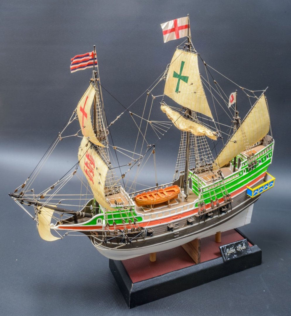
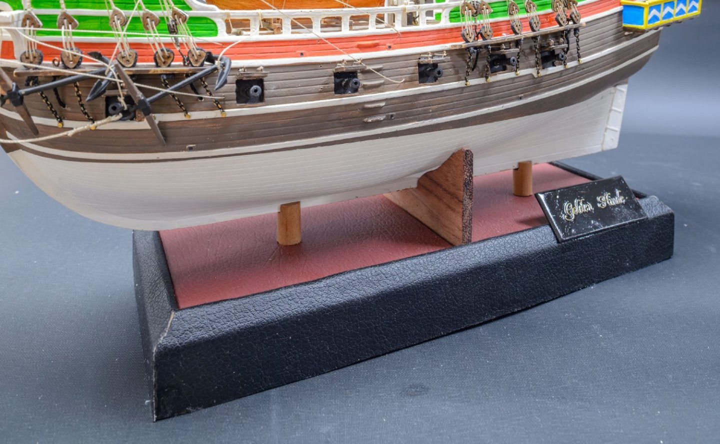
- Golden Hind
- Airfix
- (and 1 more)
-
Focus Stacking
modeller_masa replied to Dennis P Finegan's topic in Photographing your work. How to do this.
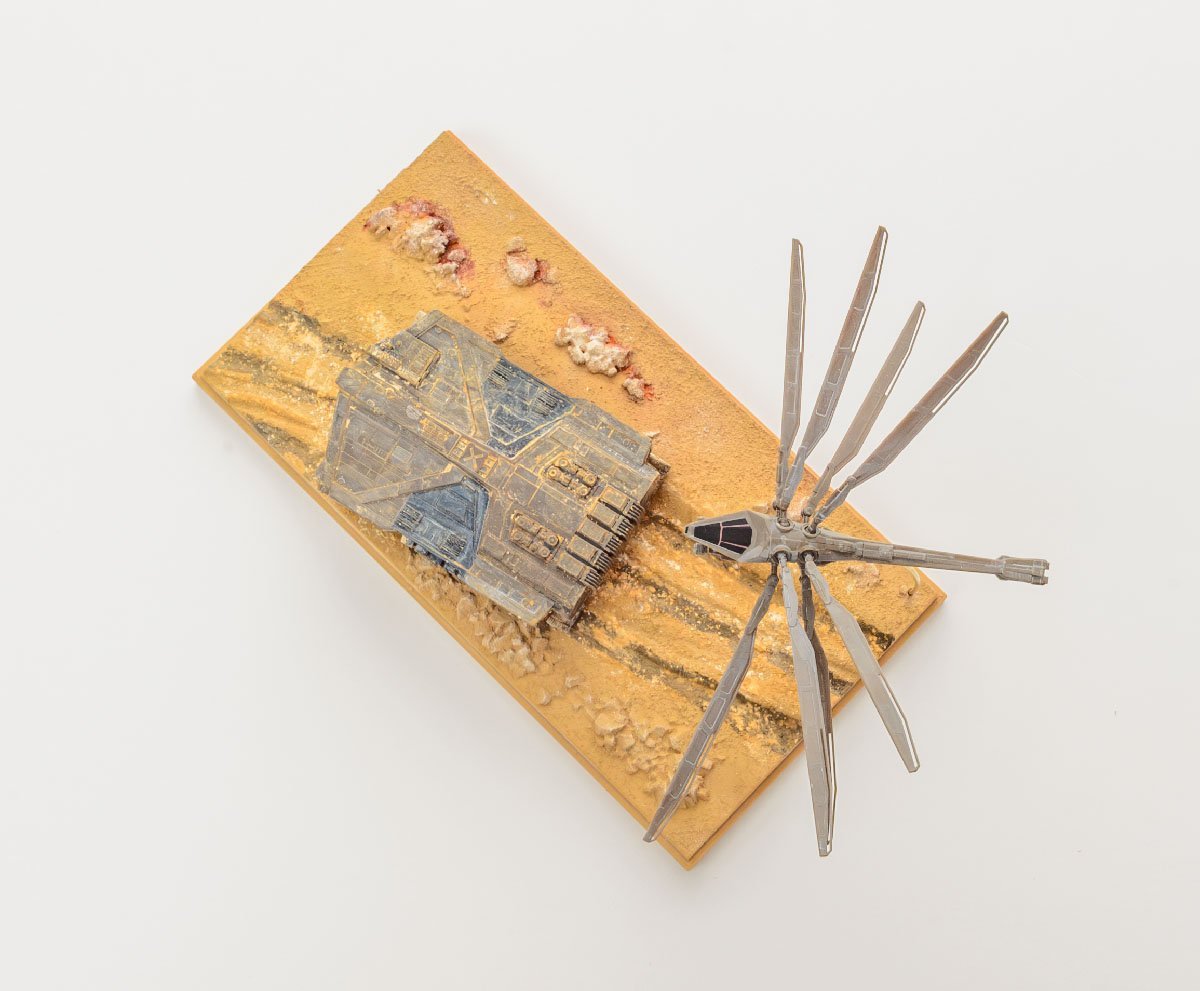
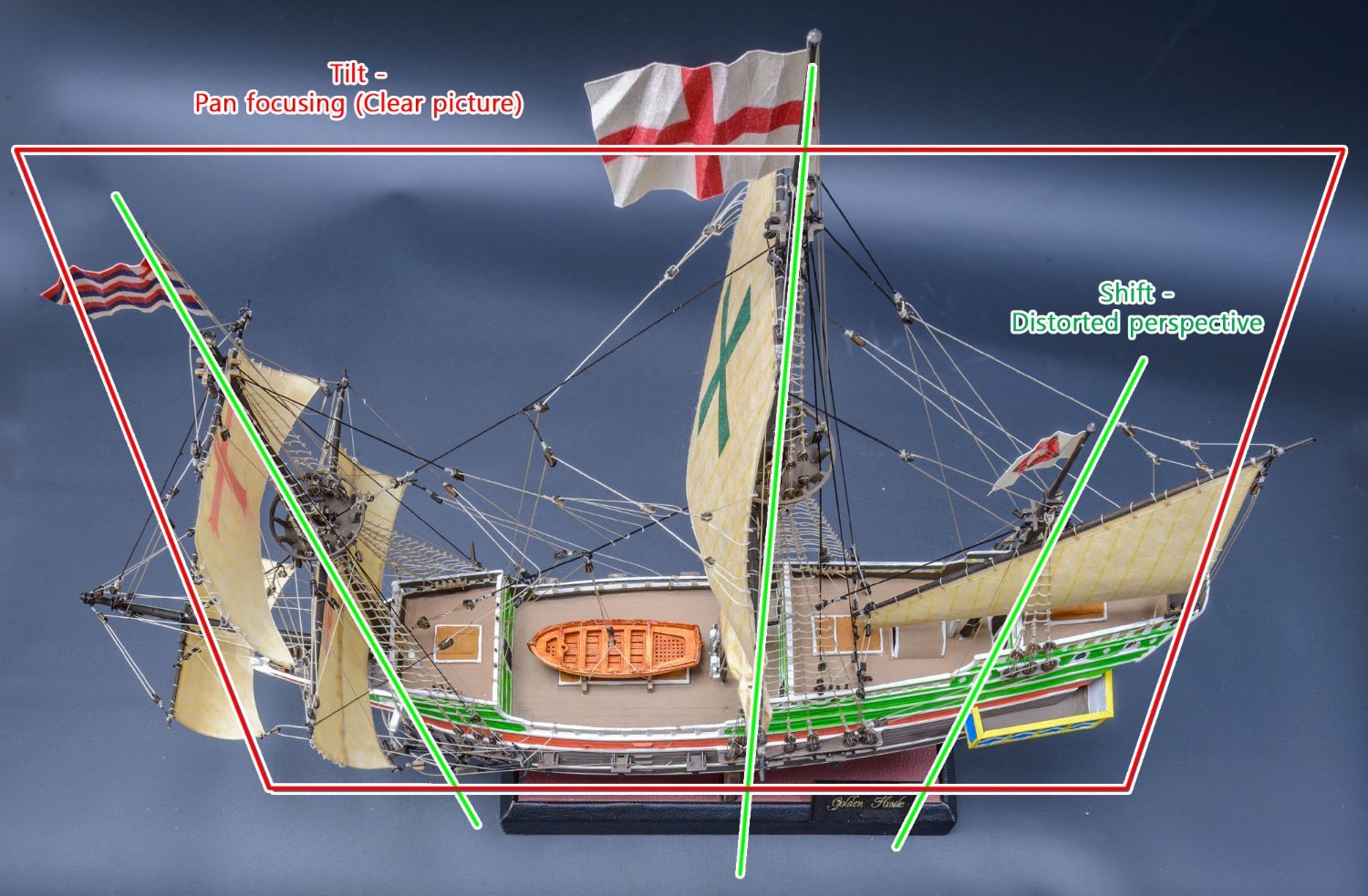
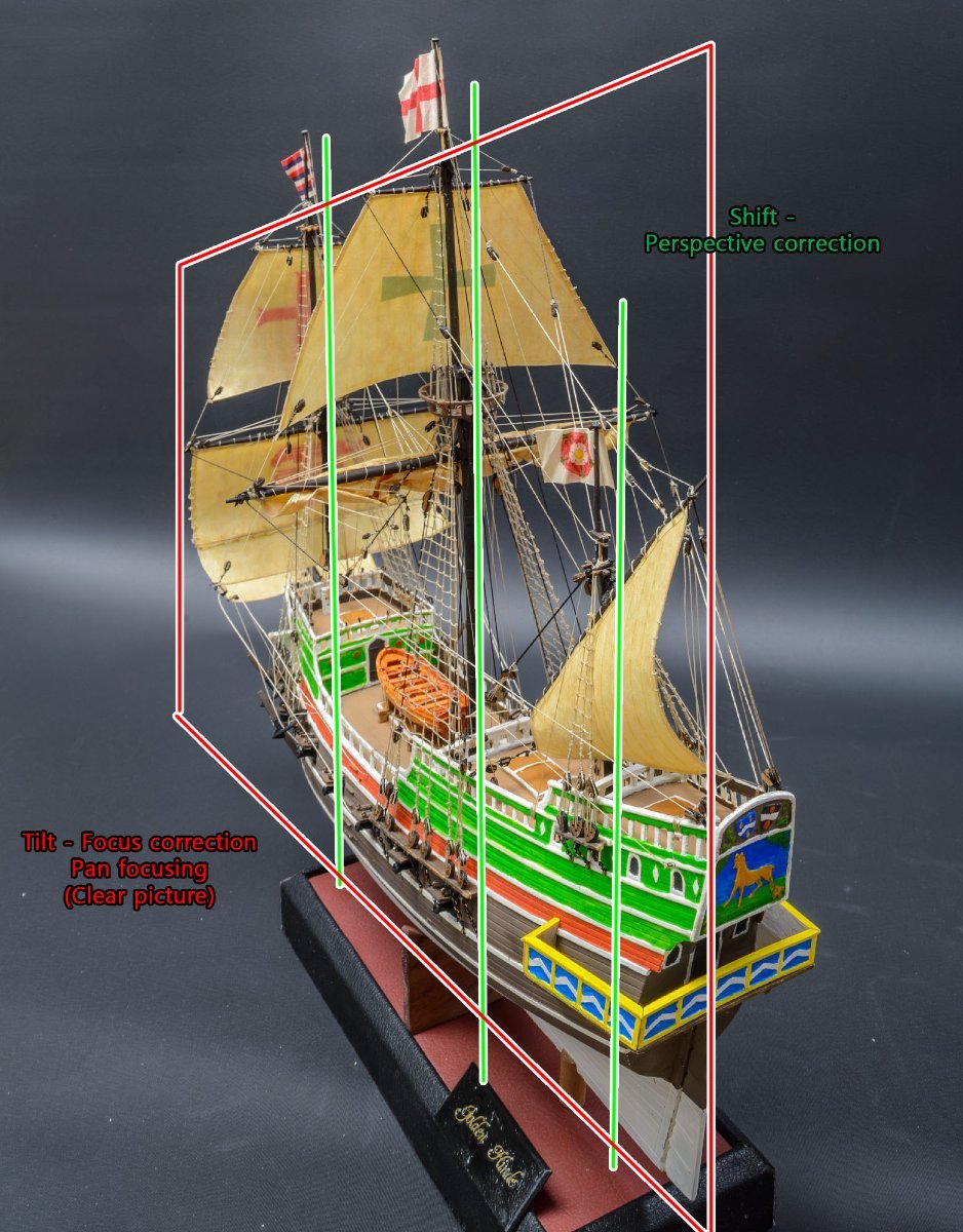
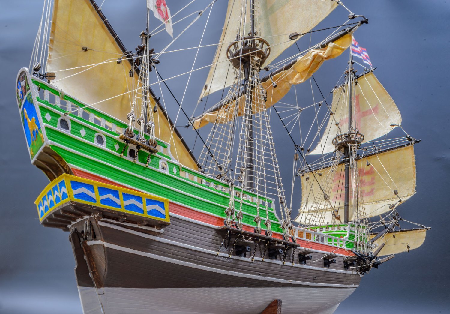
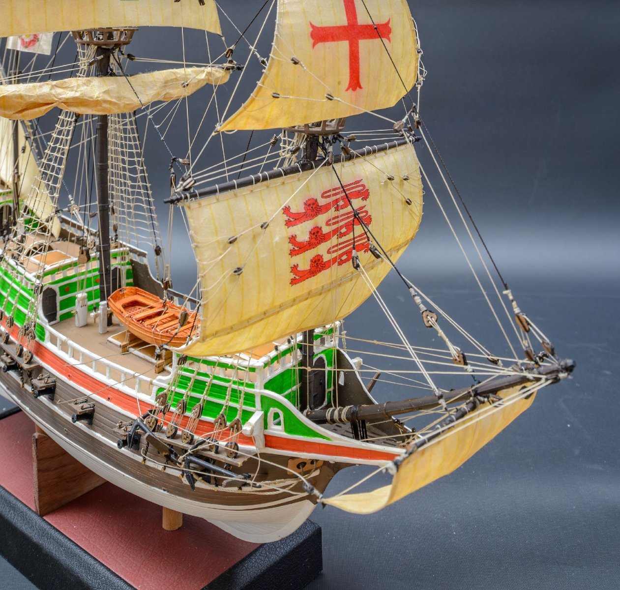
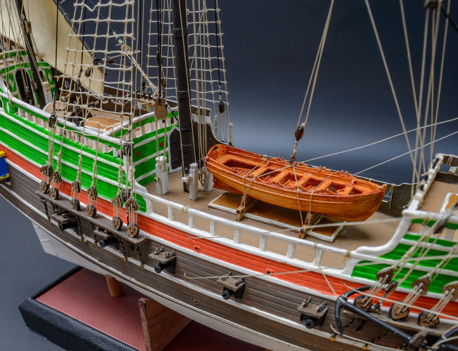
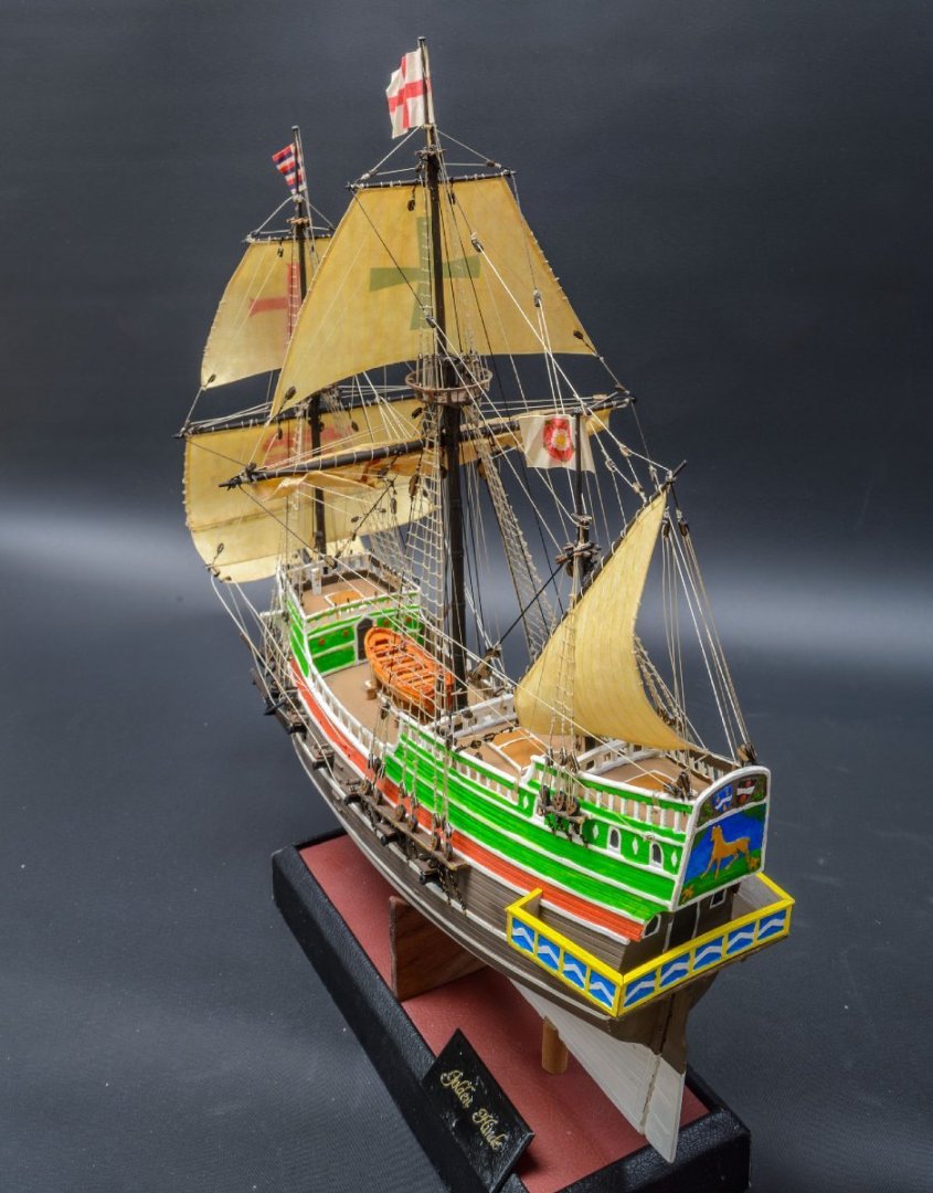
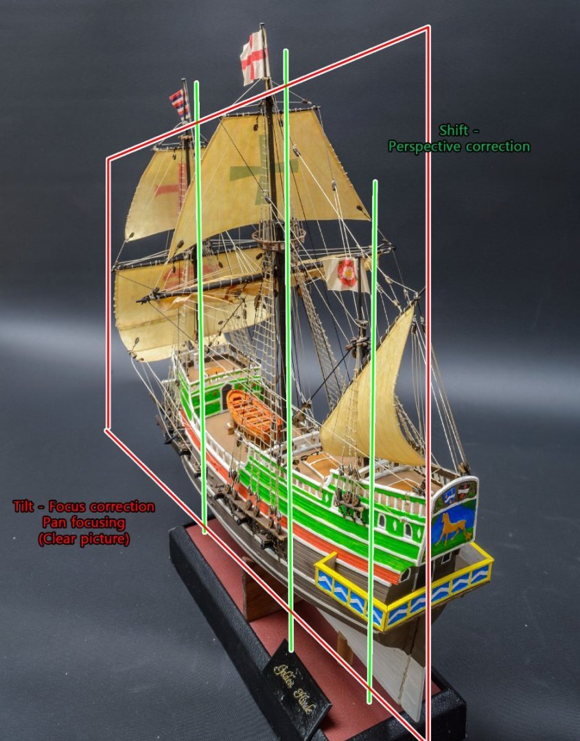
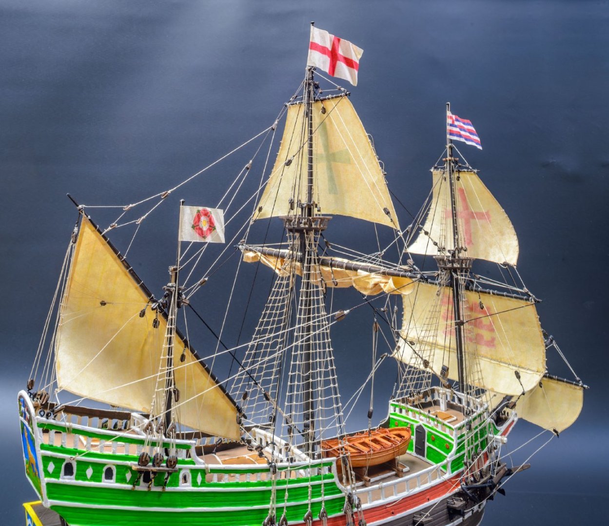
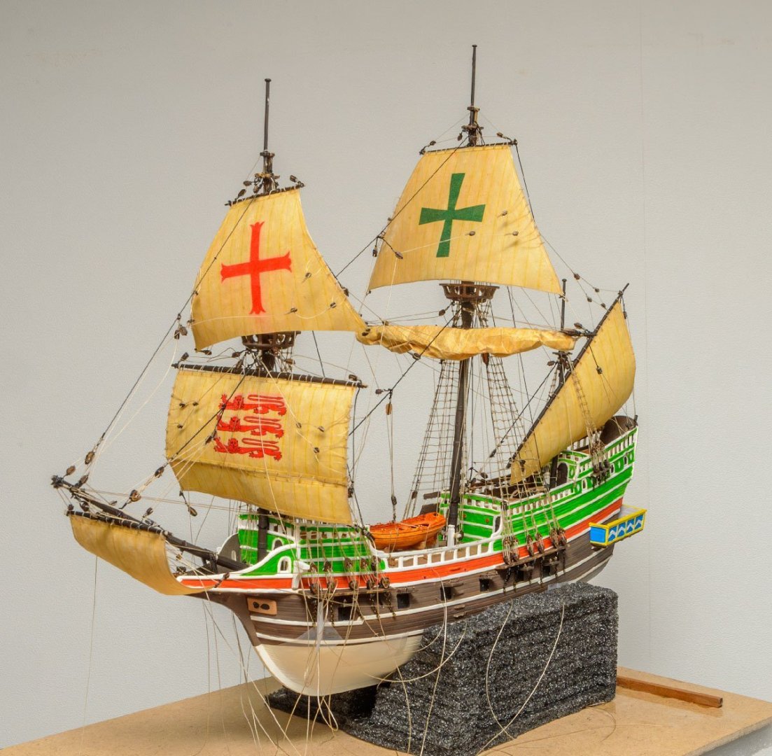
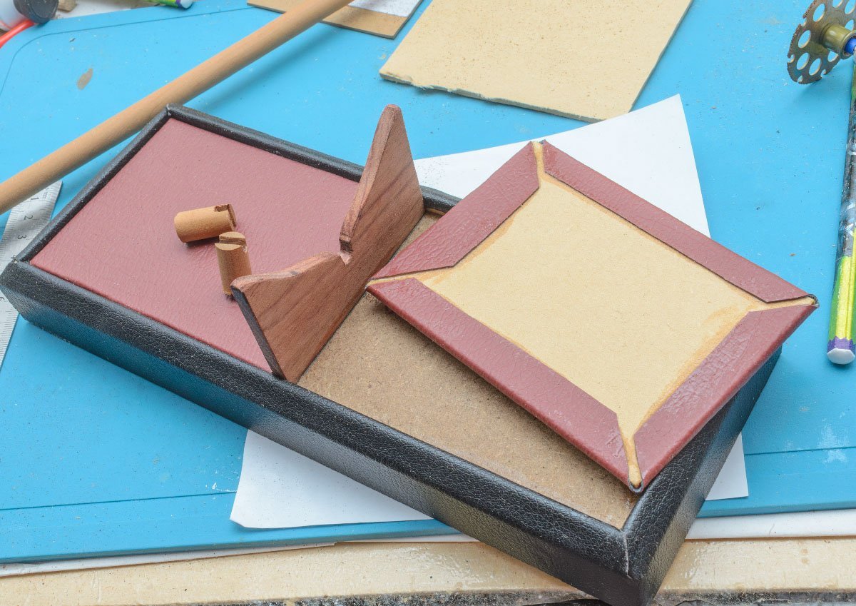
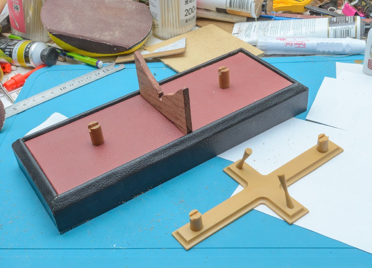
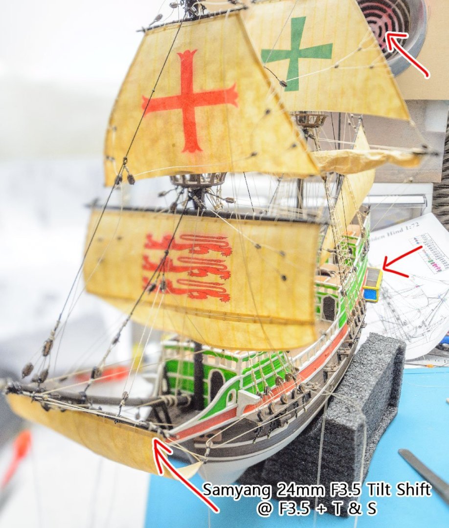
These are sample pictures that I took with a Samyang 24mm F3.5 Tilt-Shift lens. In a general situation, I may need an ultra wide angle lens with a F22 slow speed aperture or the focus stacking method to take the same picture. I took only a picture. Beautifully simple and works well. It is a case of "a practice is worth a thousand words." Another example. I can get the same perspective correction with an ultra wide angle lens and photoshop crop option, but the picture resolution will be lower than this. Difficulties with the focus stacking method have already been commented on here. Before the slim mirrorless camera age, the TS lens cost more than $2,000. The high price was a reason we had difficulties using the lens. Now we can get the old vintage lens for $300. 😎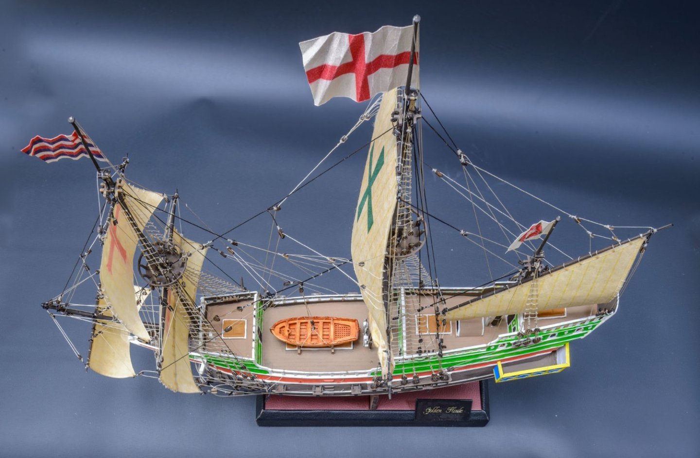


-
Thank you for your guidance, Darivs. I didn't expect the result, but I thought the straight standing rigging line is better than the zigzag line. I'll pay more attention to it next time.
-
Thank you again for your comments, Steven. I appreciate very much!
-
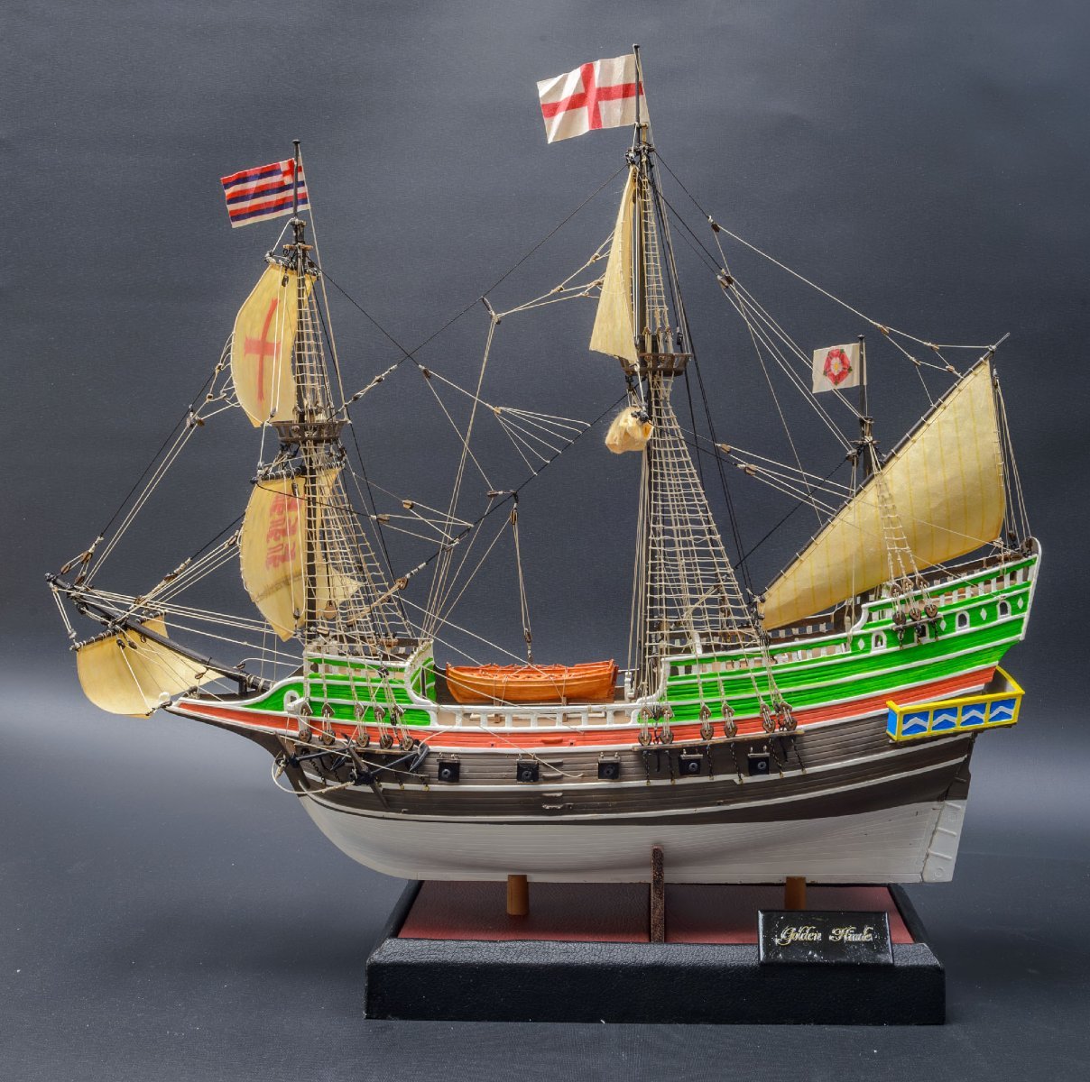
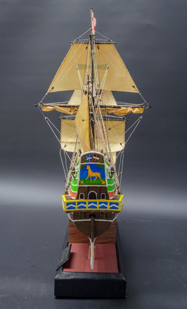
I used my 24mm F3.5 Tilt-Shift lens. The lens makes interesting pictures using perspective and depth-of-field control. I hope you enjoyed my build log. See you next month.


- 13 replies
-
- 8
-
-
-

-
- Golden Hind
- Airfix
- (and 1 more)
-
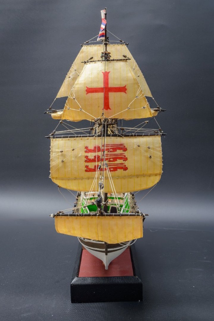
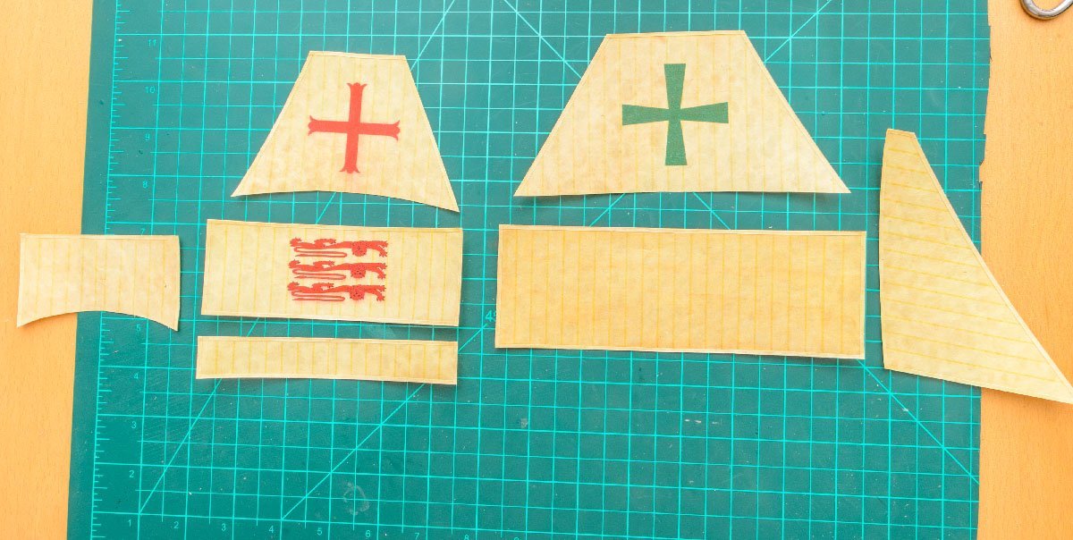
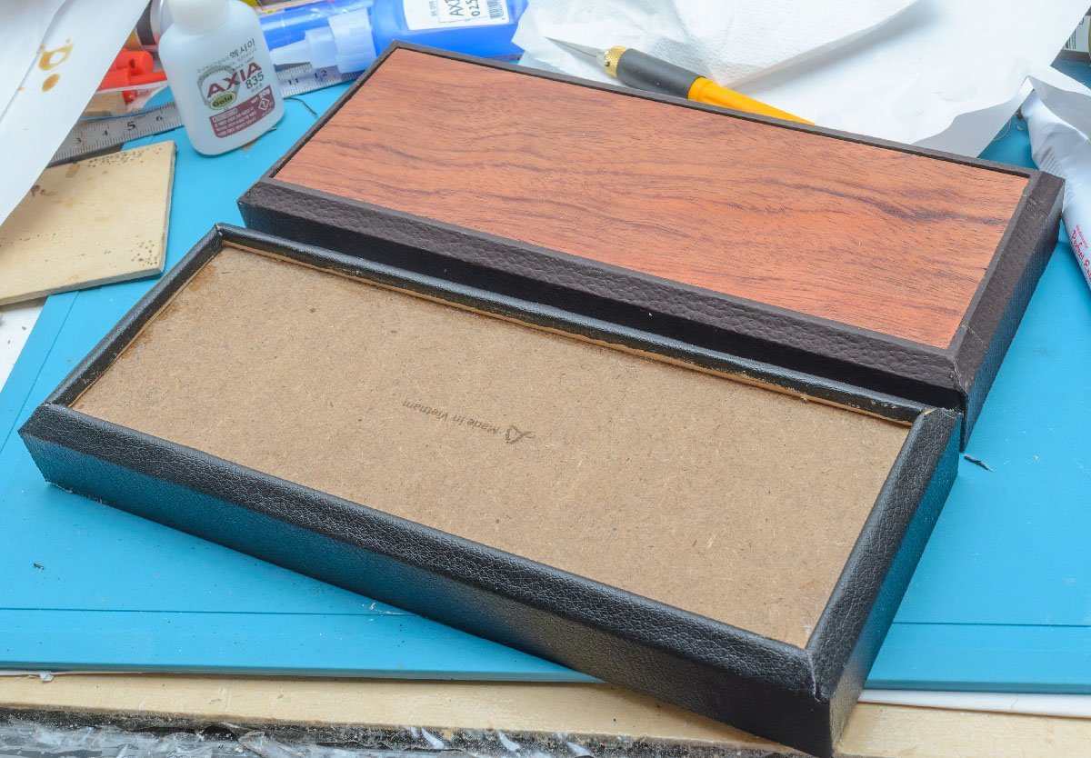
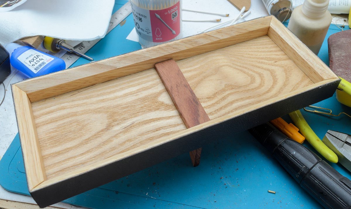
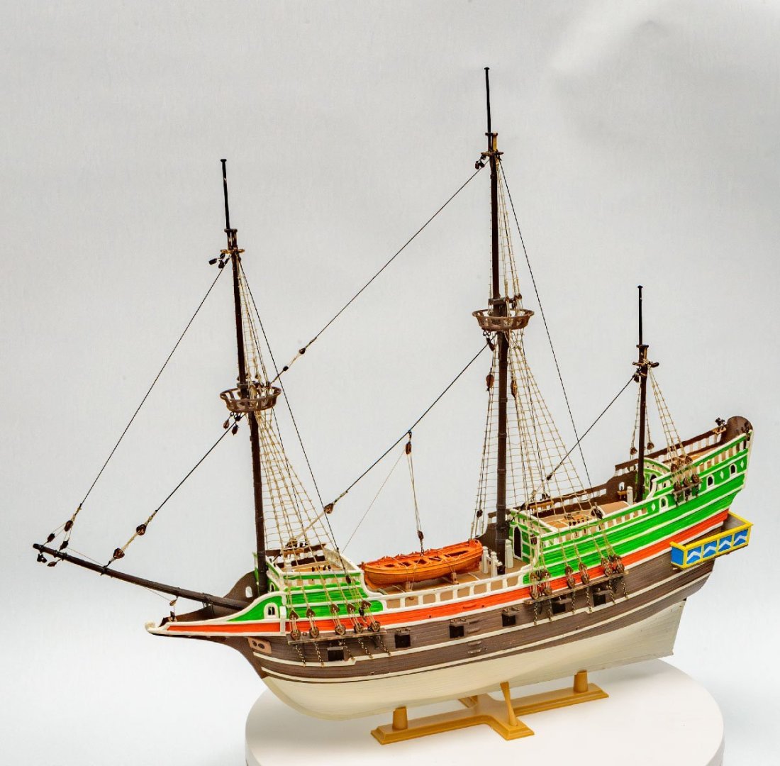
The standing rigging section was fun and solid. However, the running rigging was pretty difficult. HISmodel's running rigging plan was confusing and inaccurate. The plan includes two different Golden Hinds, so it led me to install duplicated rigging threads to the same place. I don't have enough skill and experience to fix them, so I just added all the riggings. The result was spagetti rigging. 🤣 I made sails using Han-ji. (In other words, Korean paper, silkspan, Japanese rice paper, or Chinese paper.) I used an inkjet printer to print them. I used synthetic leather to wrap a wooden tray. This was an ambitious project, but the HISmodel rigging plan made my model impractical. In the future, I'll stick to more formal references, such as the AotS book series. 😁
-
I would like to express my sincere condolences on the death of James William Byrnes... https://byrnesmodelmachines.com/
-
Focus Stacking
modeller_masa replied to Dennis P Finegan's topic in Photographing your work. How to do this.
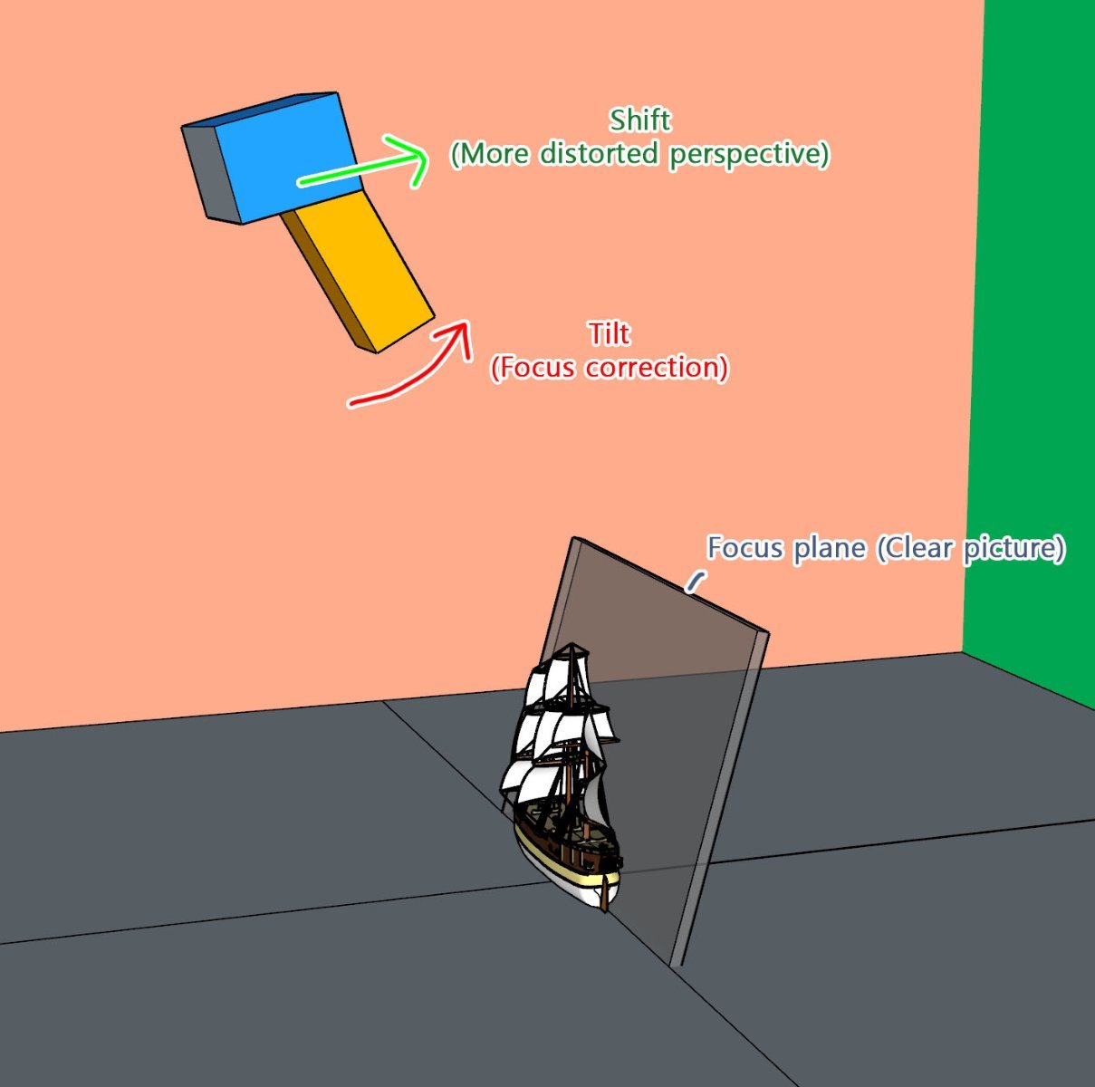
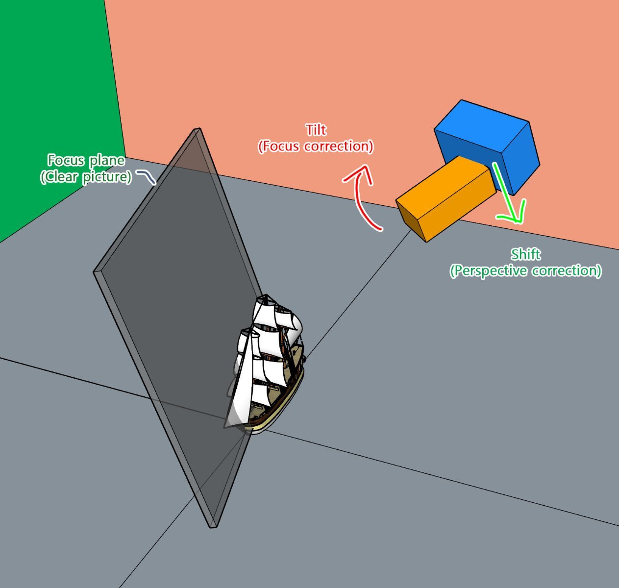
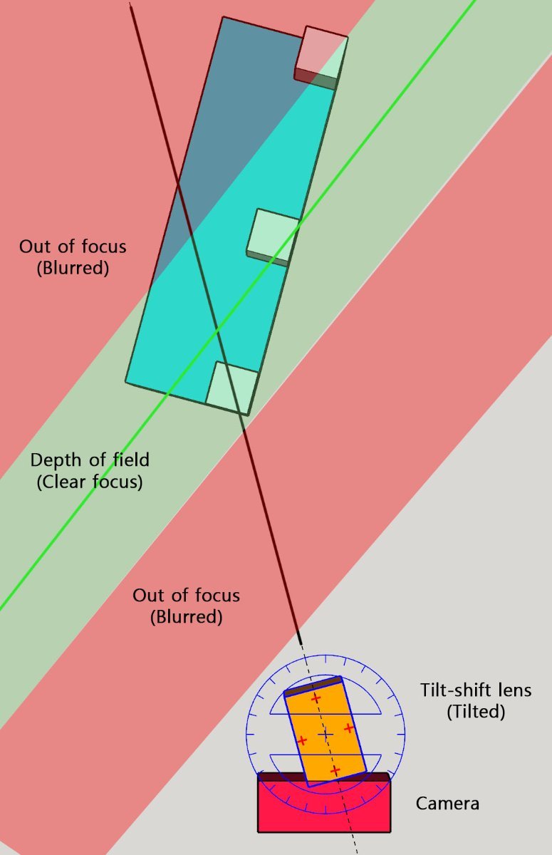
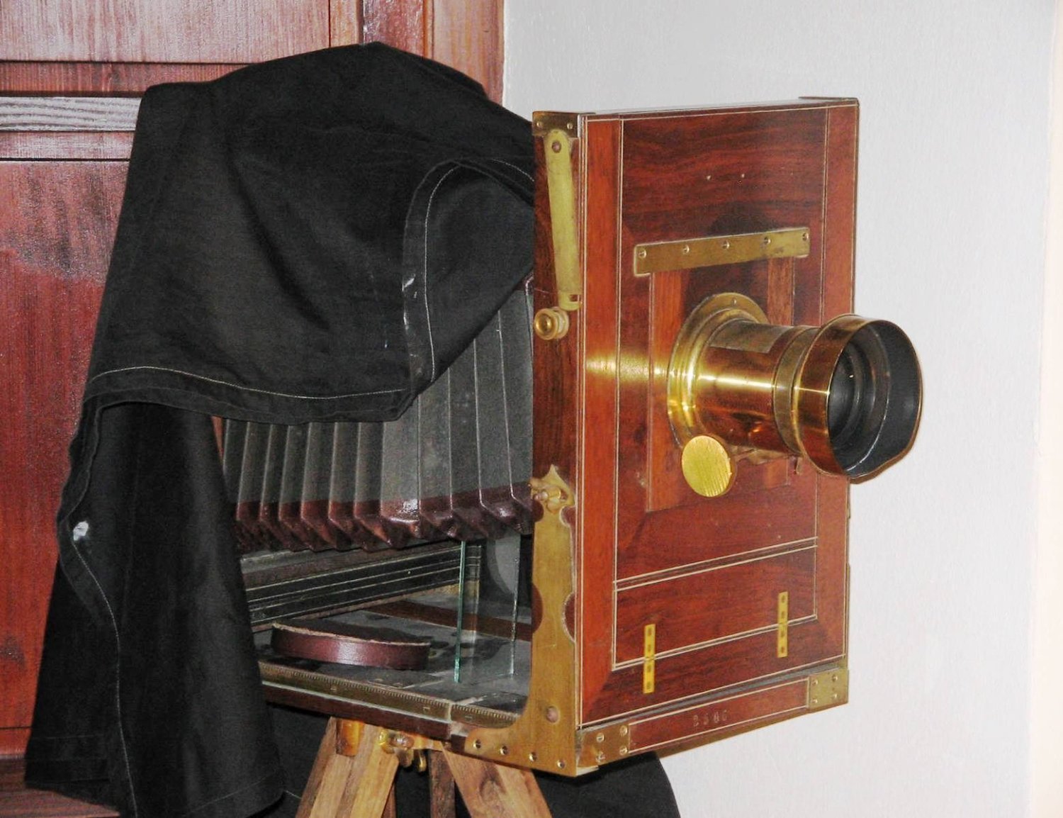
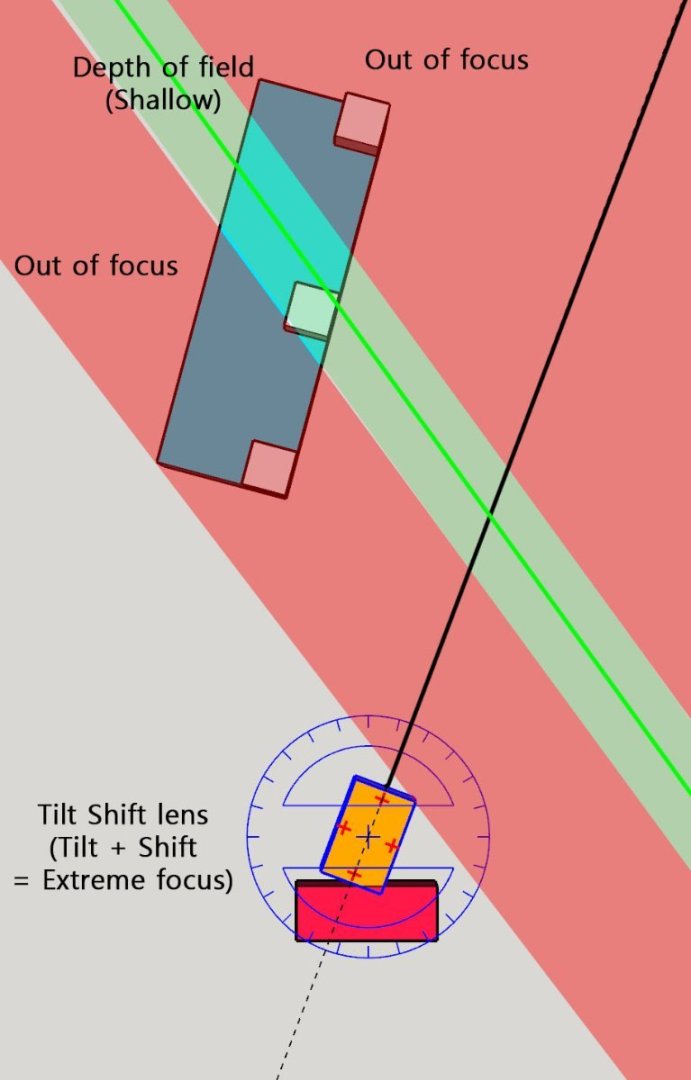
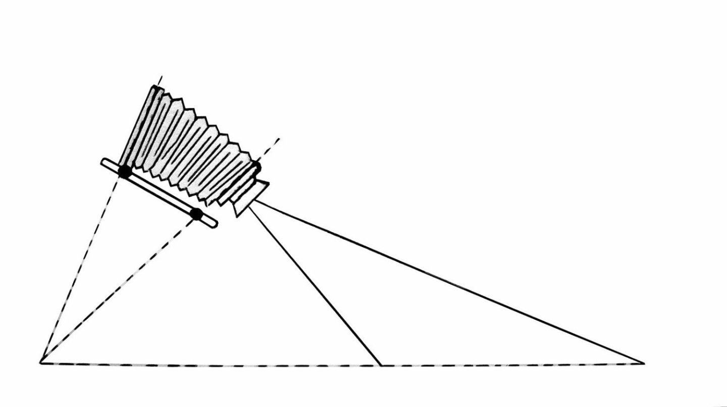
Wow, the camera is newer than me! I've been using a Nikon D4 for ten years. The built-in focus stacking became popular in the next generation. Sorry about the confusing sample pictures. I would like to show an example of the controlling depth of field. Here is a diagram of the depth of field in the case of a normal lens. There are two ways to get clear focus on the entire subject (Blue) in the given situation. 1. Small aperture - Cons: Slow shutter speed, loss of detail 2. Software photo stacking - Cons: Needs multiple pictures, frequent software rendering error - Ex: rigging threads This diagram shows how the tilt-shift lens makes a clear picture of the subject. If I tilt the lens in the opposite direction, the subject looks like a miniature. The best lens for tilt and shift control is for large format cameras. You can find cheap vintage lens on eBay. I once made a flat-bed scanner-large format camera 15 years ago. I won't use the lens because the whole device holds too big place.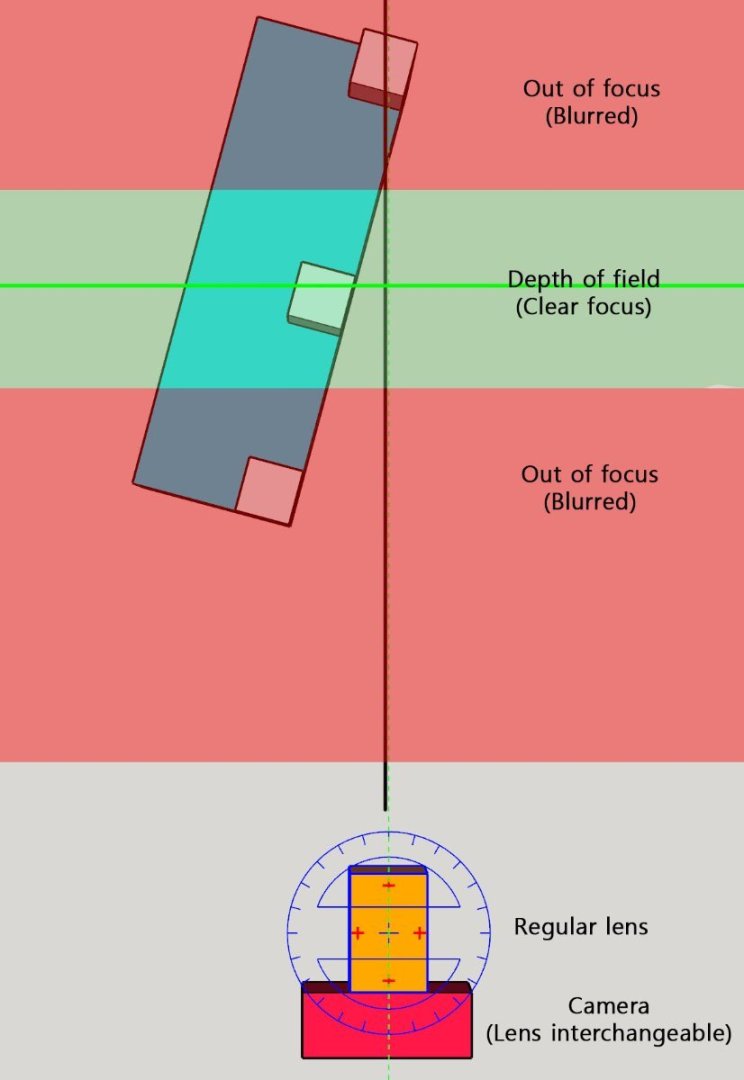


-
Focus Stacking
modeller_masa replied to Dennis P Finegan's topic in Photographing your work. How to do this.
It works like magic! I'm not afraid of out of focus issue. 😎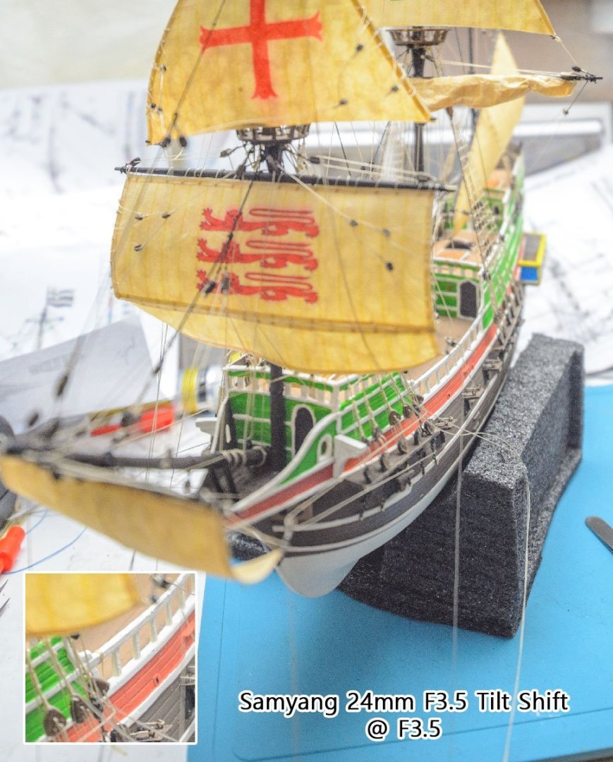
-
Focus Stacking
modeller_masa replied to Dennis P Finegan's topic in Photographing your work. How to do this.
I'll buy a 24mm F3.5 Tilt Shift lens for my DSLR today. ($250) It is cheaper than an electric dolly rail. I thought the lens is the most simple solution for given budget. -
https://www.subchaser.org/model-anchor-chain According to the US Submarine Chaser archive site, this is the the optimal scale of railing anchor chain in the WW I era. 1:24 16 LPI (Links per inch) 1:32 21.5 LPI 1:48 32 LPI 1:64 43 LPI 1:74 49 LPI 1:96 64 LPI https://floatingdrydock.com/more.htm#CHAIN I found this site is selling the 50 LPI chains, but I don't guarantee it because I've never bought anything at the site. https://www.labellemodels.com/chain-p-295.html https://www.builders-in-scale.com/bis/parts-chain.html Another 40 LPI chain.