Bill97
-
Posts
2,731 -
Joined
-
Last visited
Content Type
Profiles
Forums
Gallery
Events
Everything posted by Bill97
-
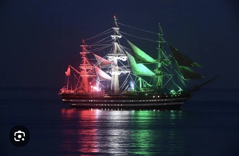
No apologies necessary Trevor. This is a stock photo if the AV alluminated at night. It has spot lights the colors of the Italian flag that shine up onto the mast. I also like the random cabin lights effect. That is my attempt instead if all on or all off.
-
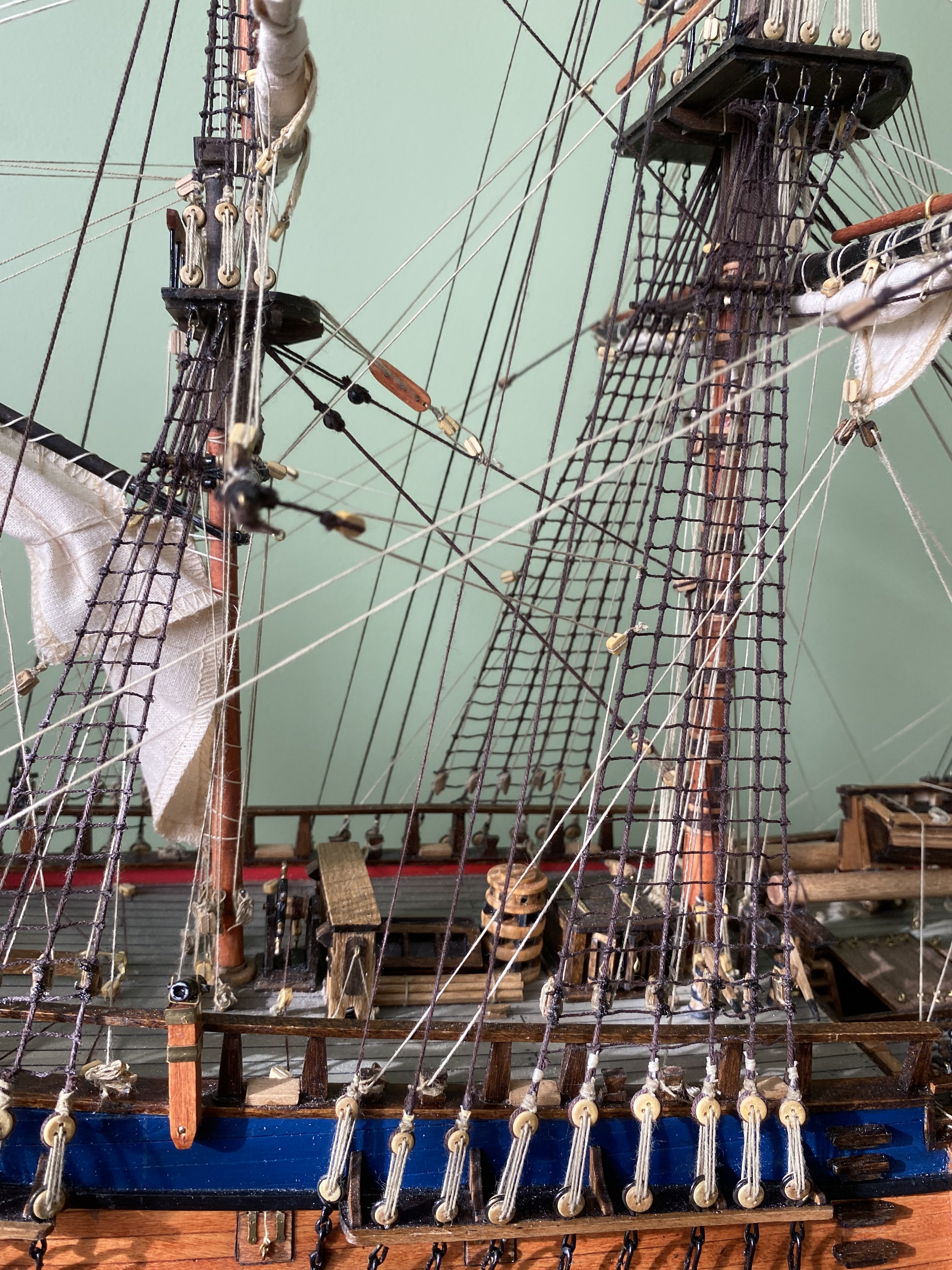
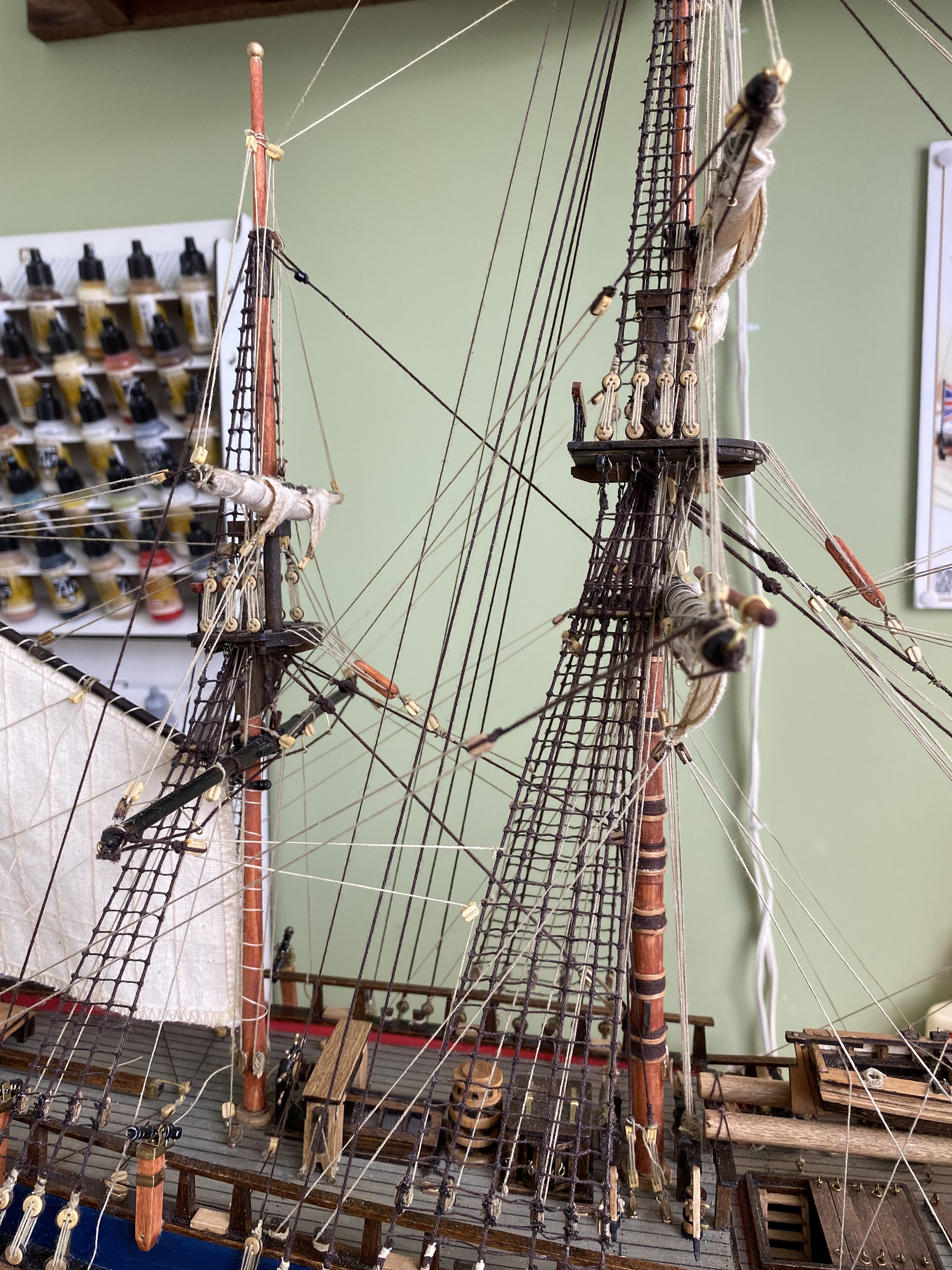
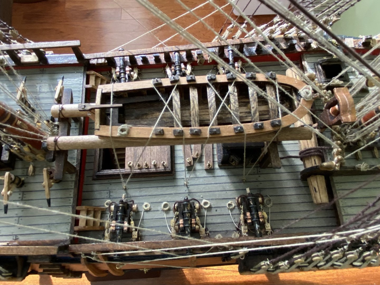
Marc my next build is going to be the wooden OcCre Amerigo Vespucci. I am going to attempt to follow the lead of another OcCre Amerigo Vespucci builder DanielD here on MSW. He is wiring his model for full lighting on 4 or 5 separate circuits to display several different lighting arrangements. I hope I can come close to doing as well as he did. I am also going to take a little artistic license with this build. On past builds I have tried to stick as close to authentic as my skills permitted. On this AV build I am going to step outside the authenticity box and be a bit more artistic in my presentation. One thing I am going to do is lay a herringbone pattern deck planking. I have layed herringbone pattern wood floors and really like the appearance.
-
Thanks Veszett. I appreciate your comments. I am able to pair my iPhone with my TV. So I take a photo of a particular spot where I am working (ratlines, etc) and then pair the phone to the TV. I am then able to expand the photo to my big screen and really examine what I am doing. Helps my old eyes a lot. A negative if doing that is I see the provided OcCre thread is fuzzy even though I run every thread through beeswax 😊.
-
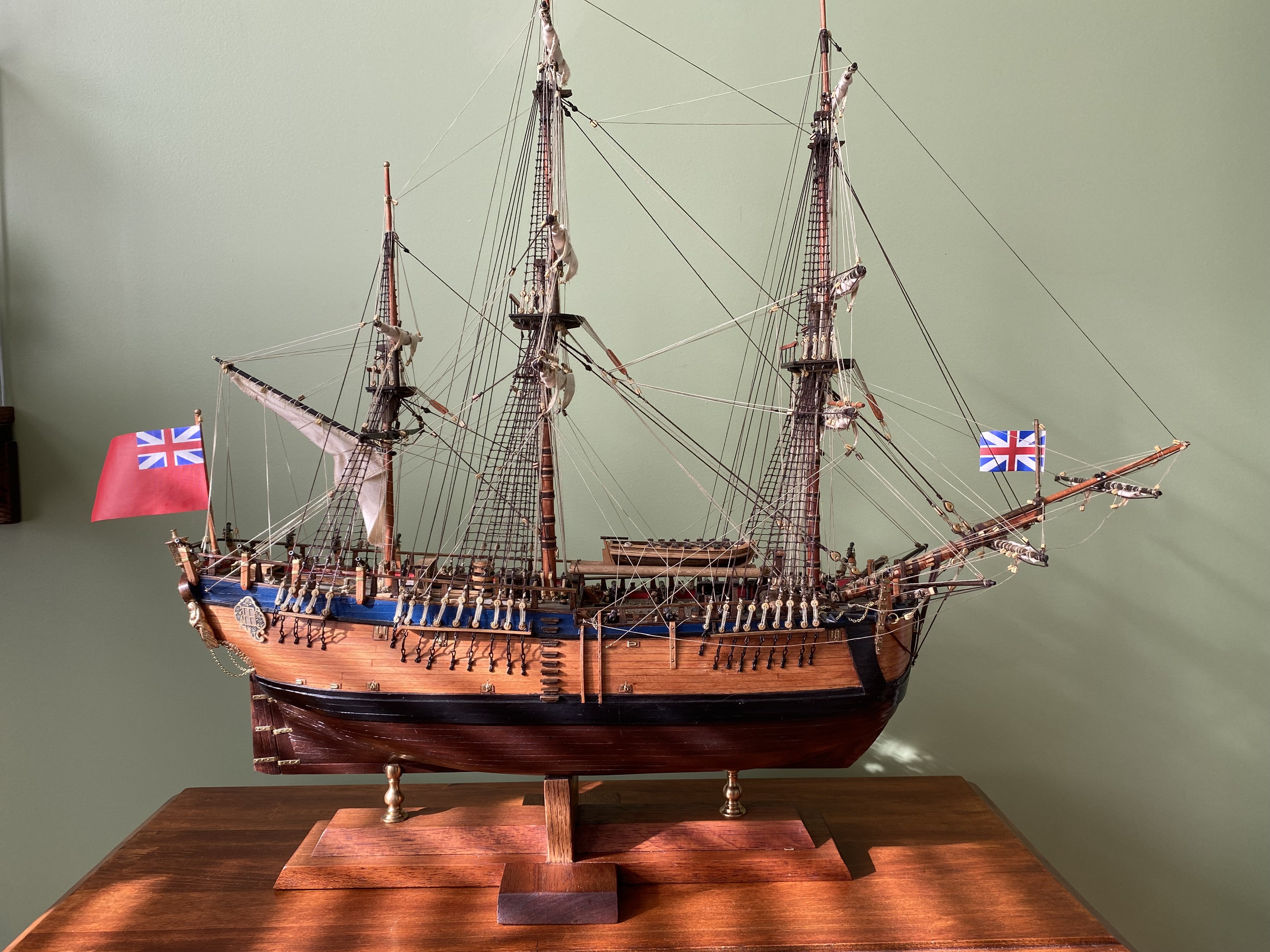
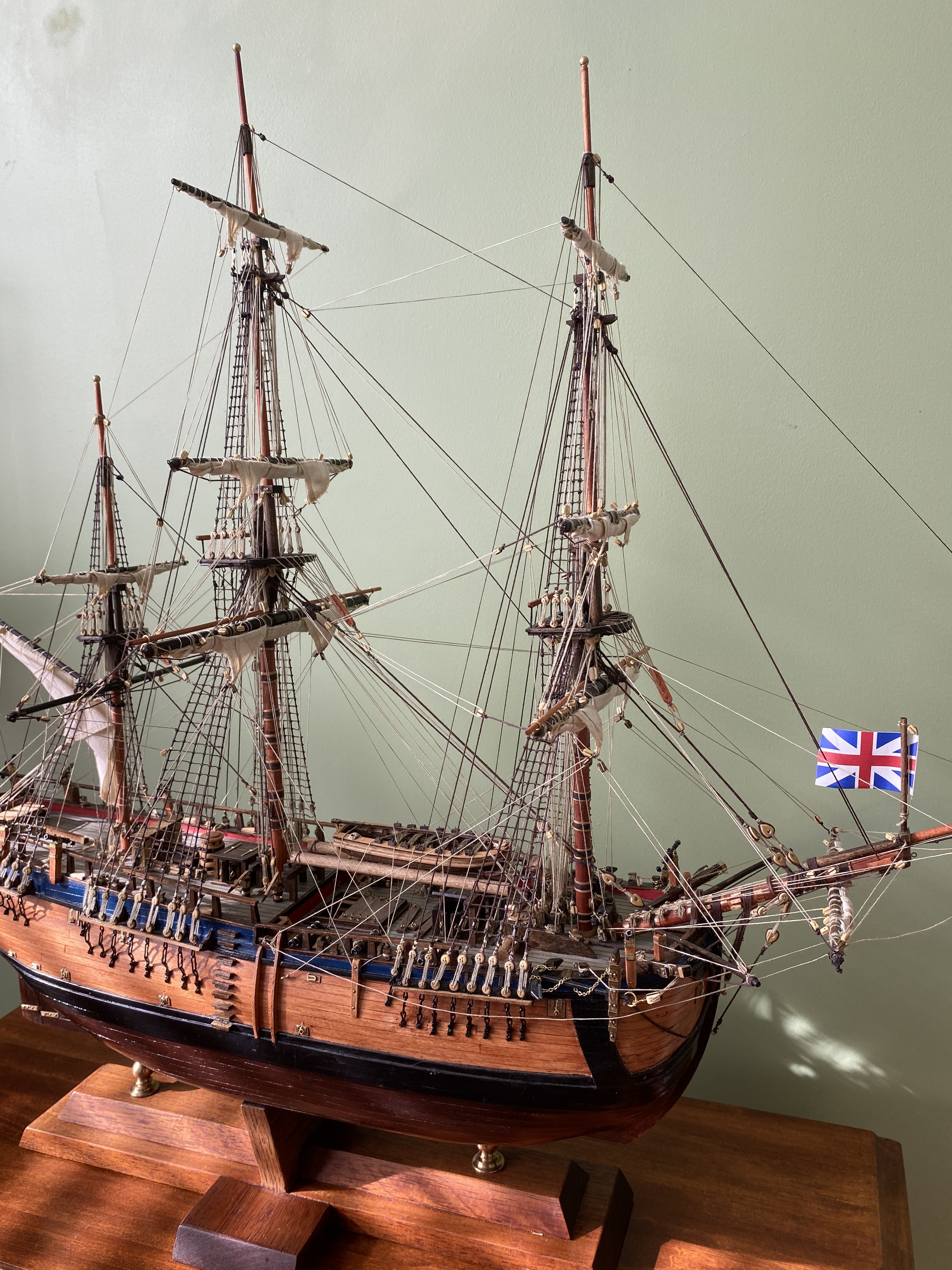
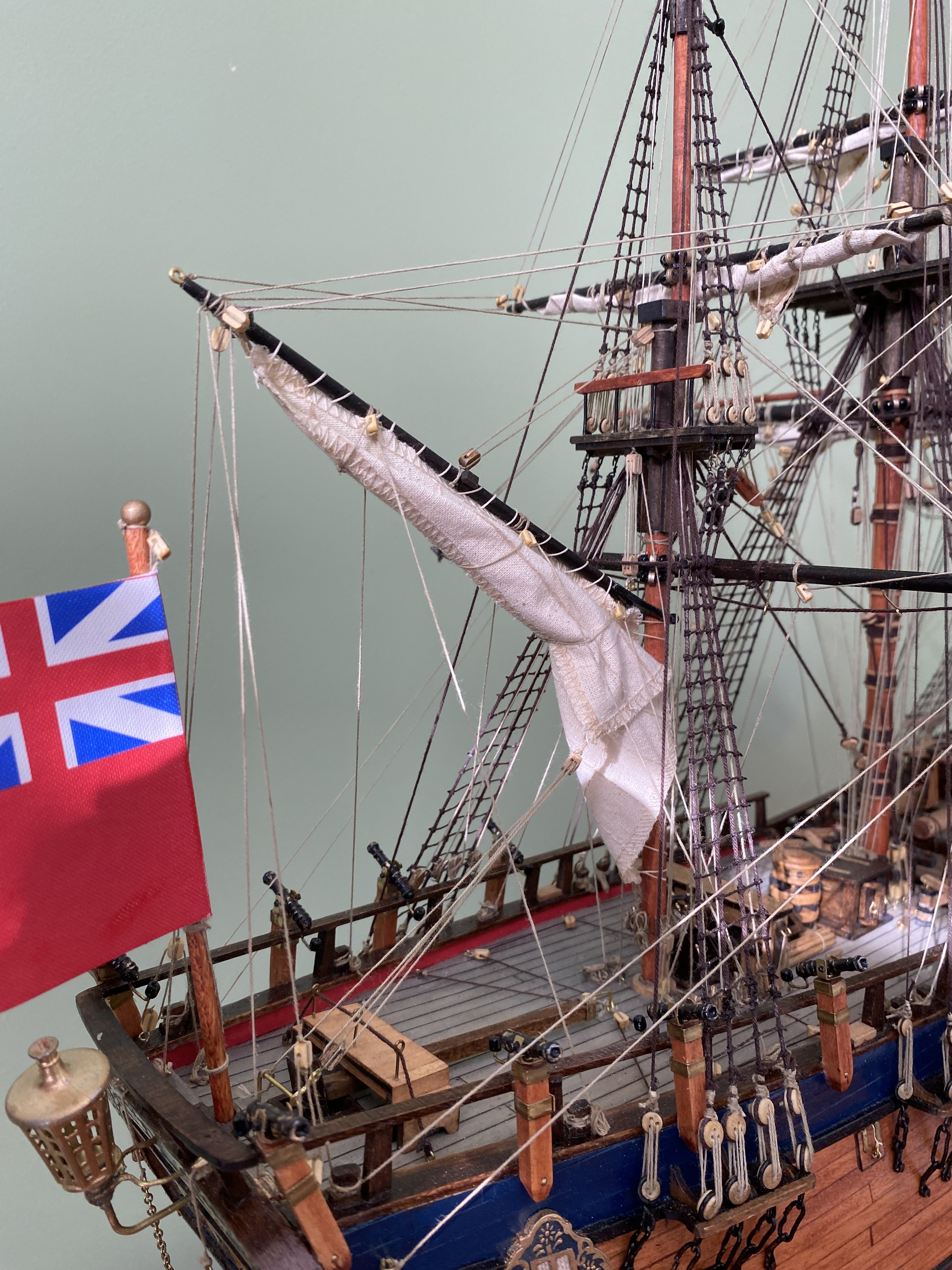
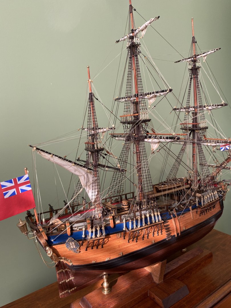
Thanks Trevor. It was a real pleasure building this ship.
-
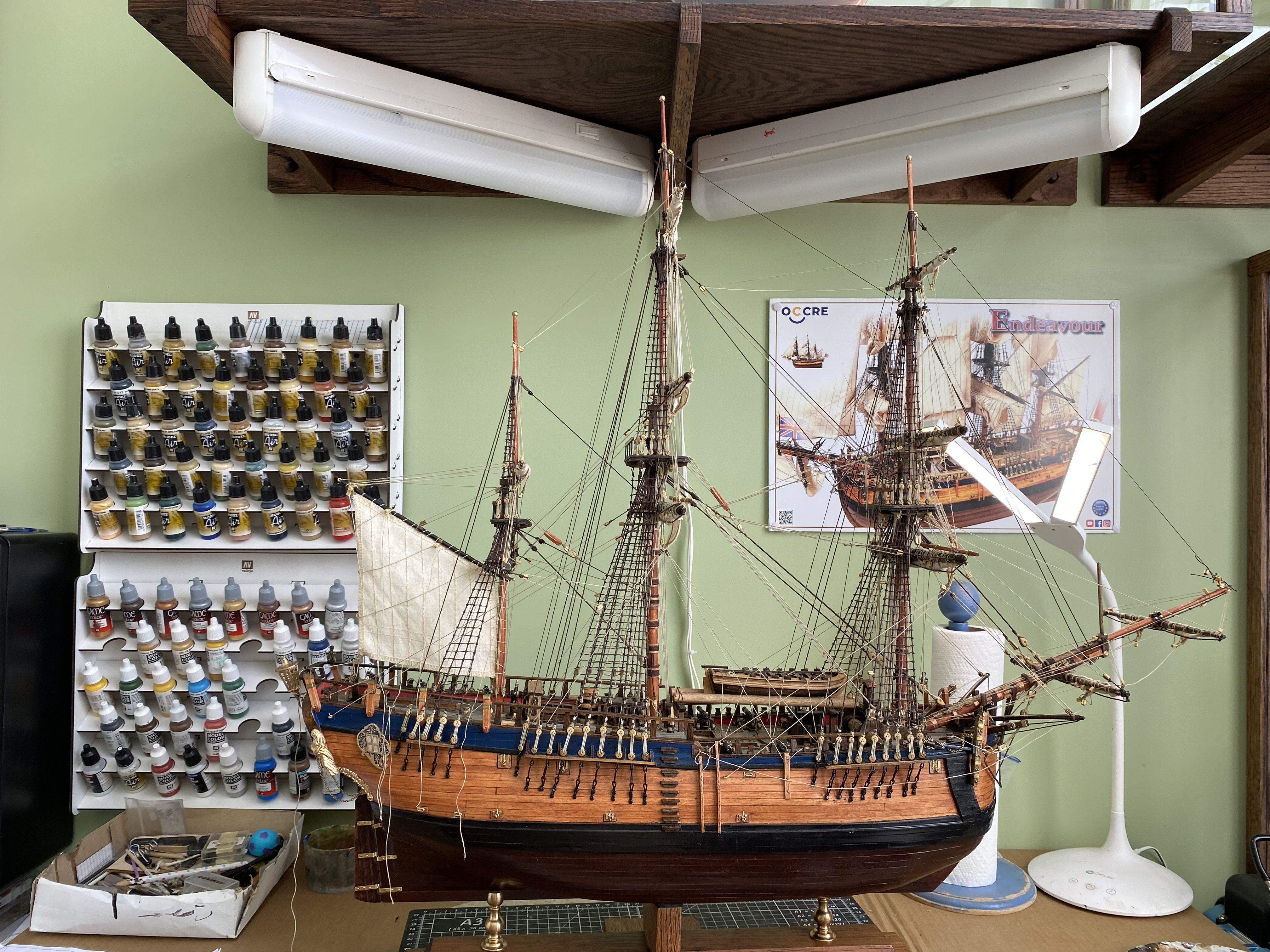
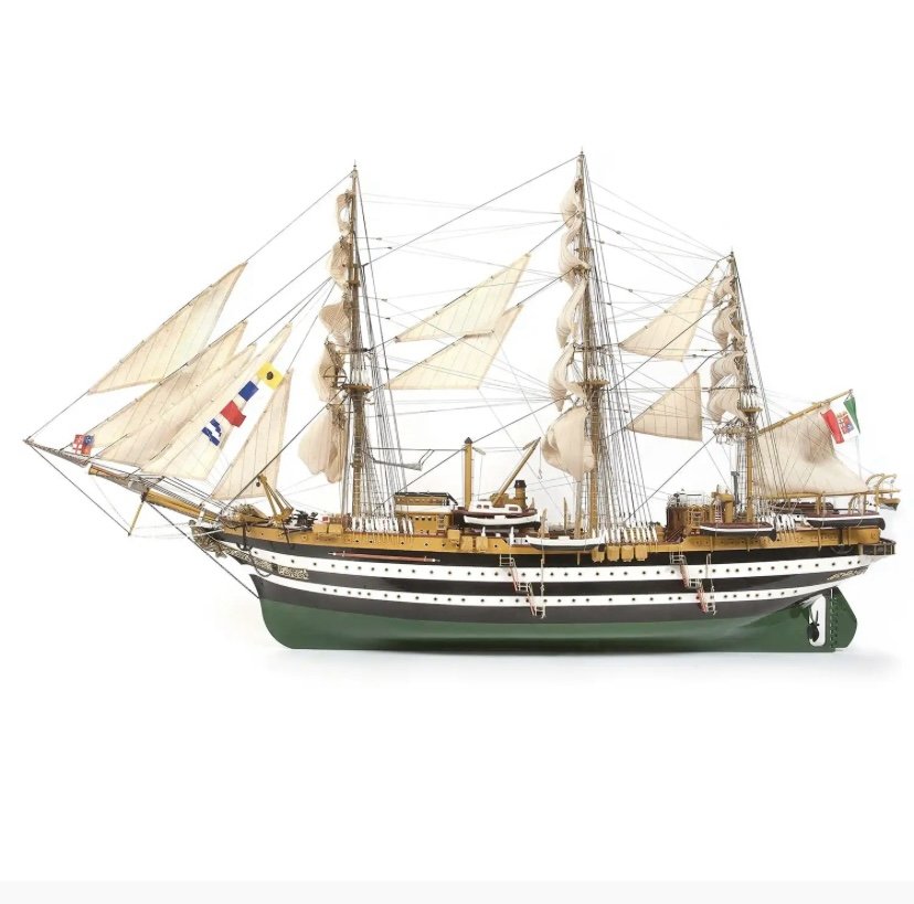
I am about to open and start my next project the OcCre 1-100 Amerigo Vespucci. You are invited to come along for my journey. I just completed the OcCre Endeavour which was my first wooden ship and was very impressed with the quality of the OcCre kit. I have no doubt the Amerigo Vespucci will only enhance my view of OcCre models.
-
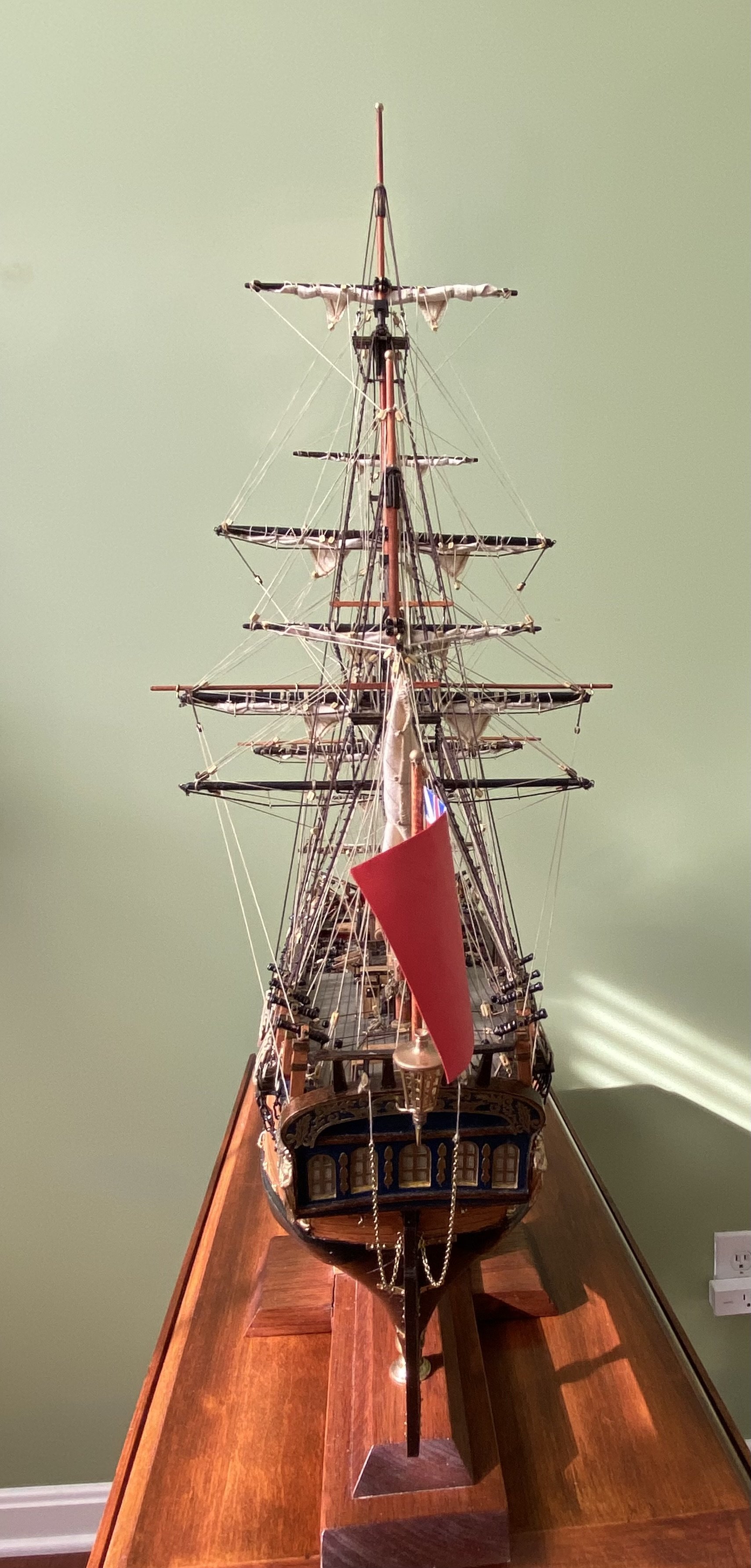
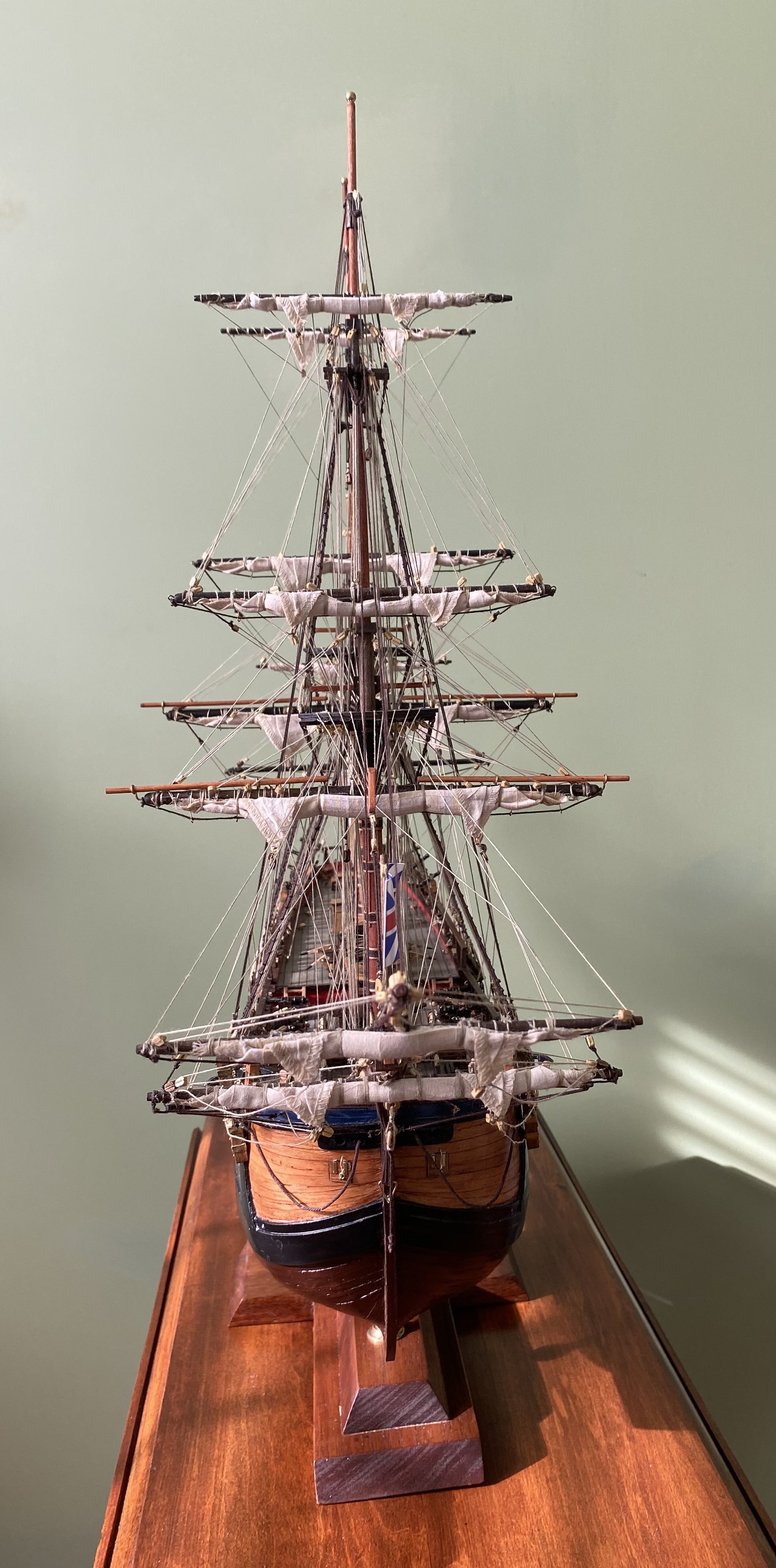
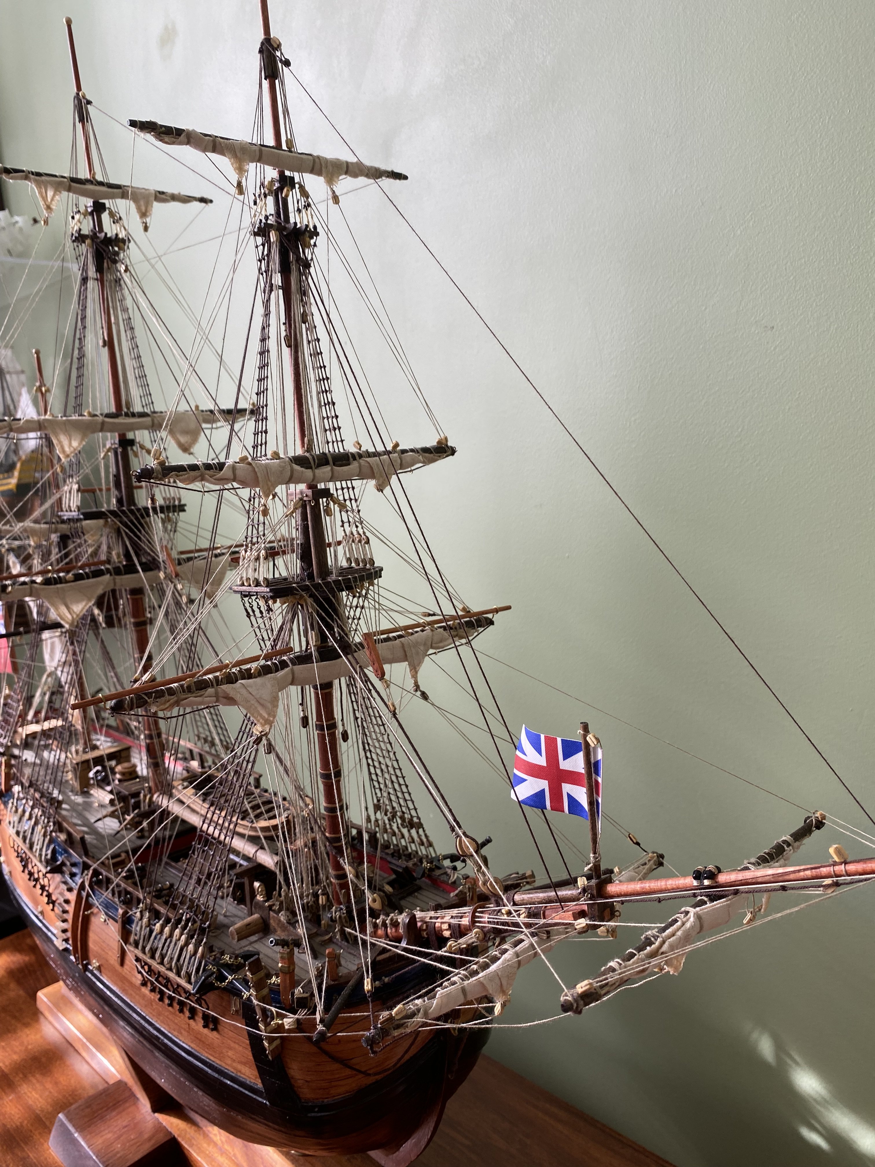
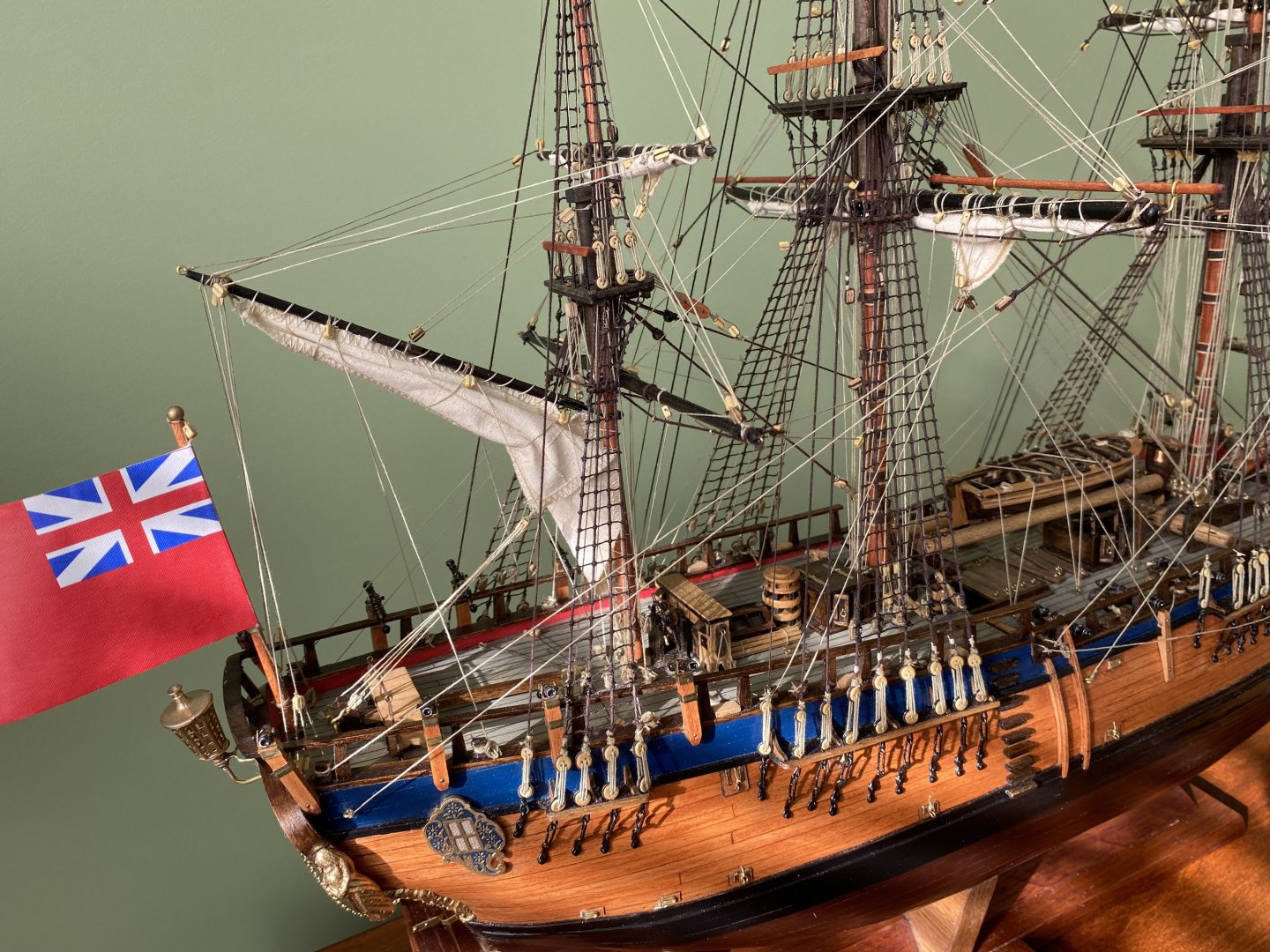
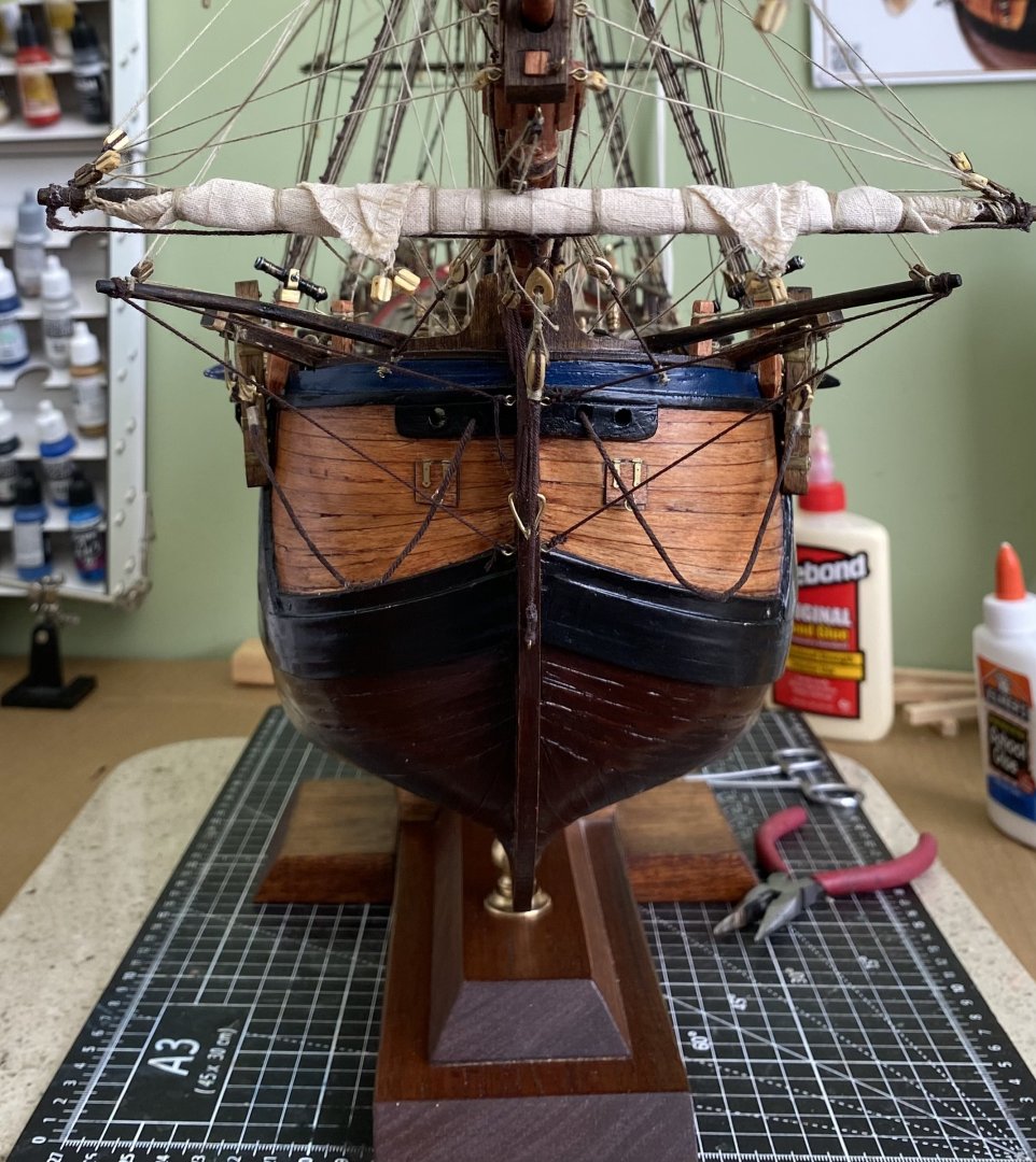
Gentlemen aside from adding a few more coils at belay points this beauty is finished. It has been a great pleasure building my first wood model. It has also been a great pleasure interacting with you guys on another build. I consider you guys great friends even if only through this fantastic web site.


- 364 replies
-
- 15
-

-

-
Daniel I am adding the final touches to my OcCre Endeavour and will soon crack open my Amerigo Vespucci kit. I have limited my excitement and preliminary research on the AV so as not to steal my enthusiasm away from the Endeavour. I am now ready to jump in and I have started rereading your build log along with Mike’s comments. For all my previous ship builds I have tried to stay as authentic as my research and skills permitted. You are going to think this crazy but for my AV my plan is to step outside the box and employ some artistic adaptations I think will enhance the beauty of the ship while not being totally authentic. I will be setting up my build log real soon and will add the linc to a comment here.
-
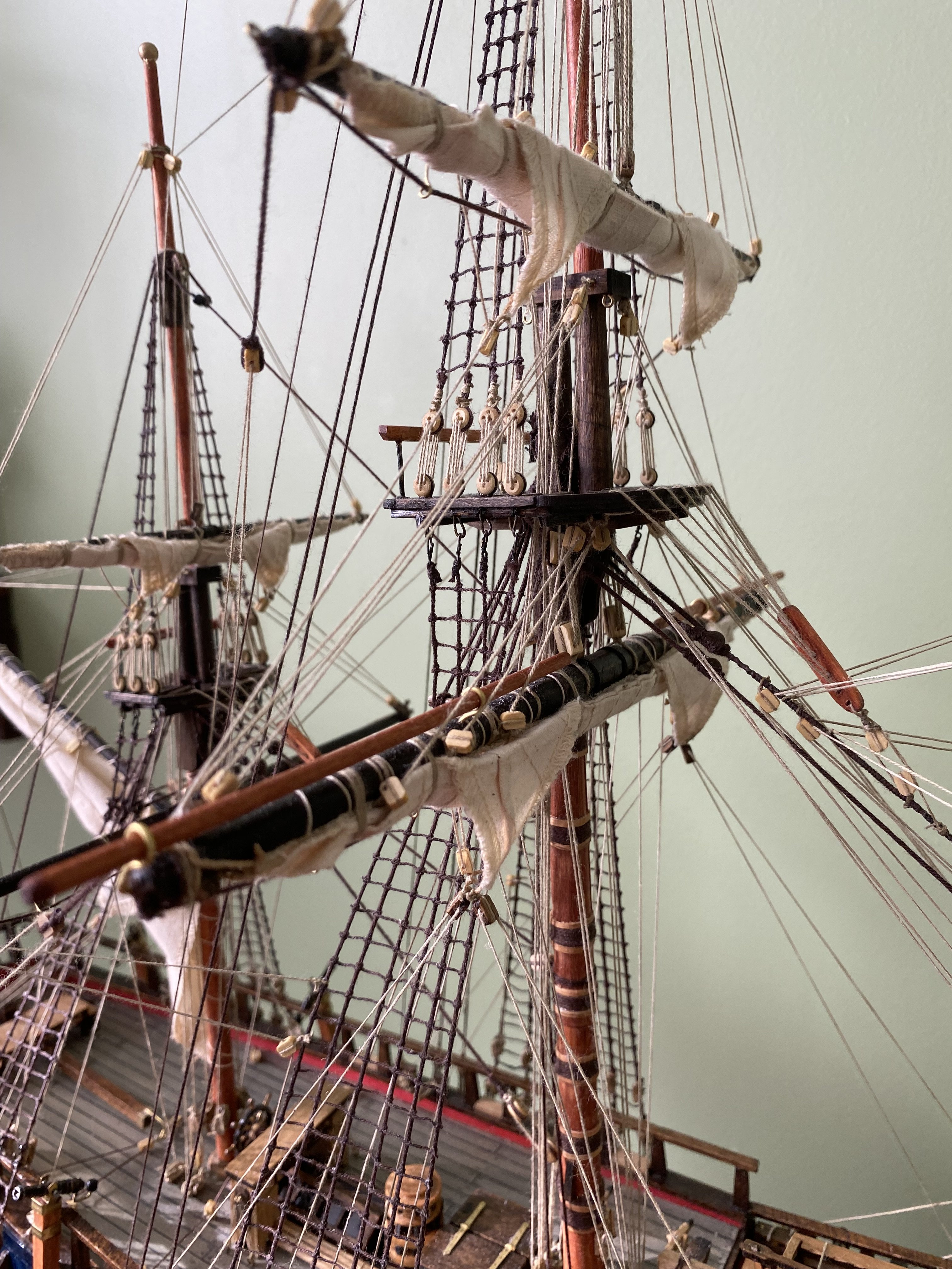
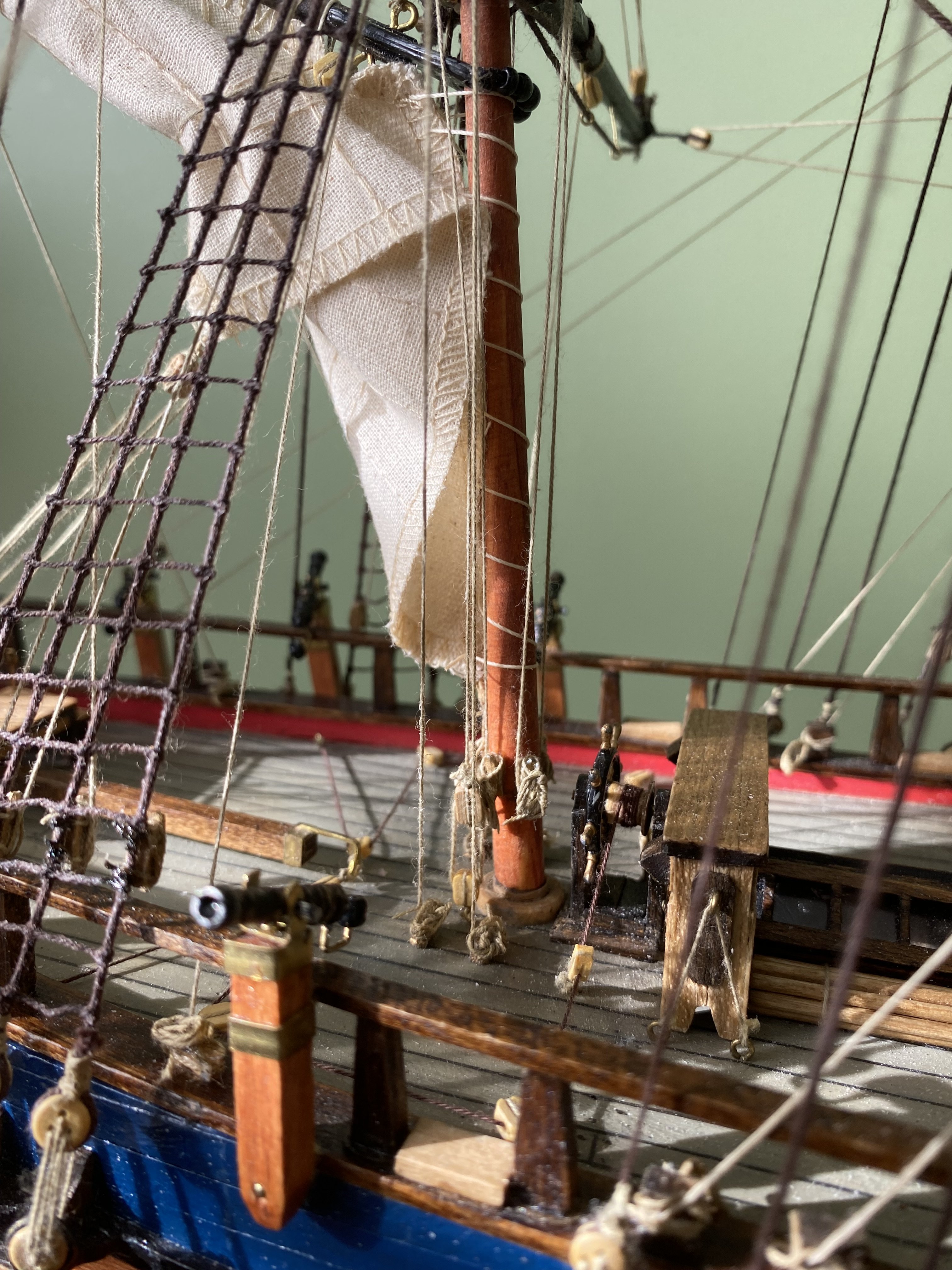
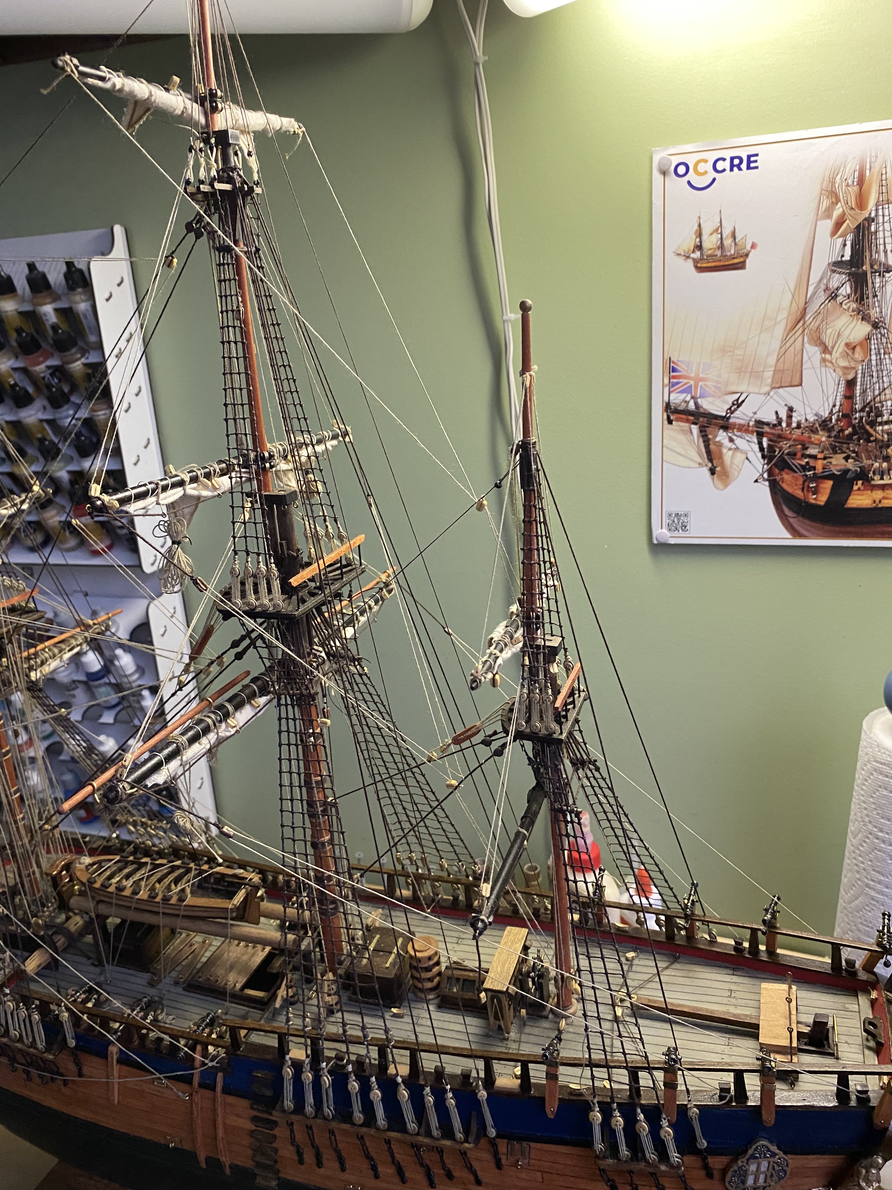
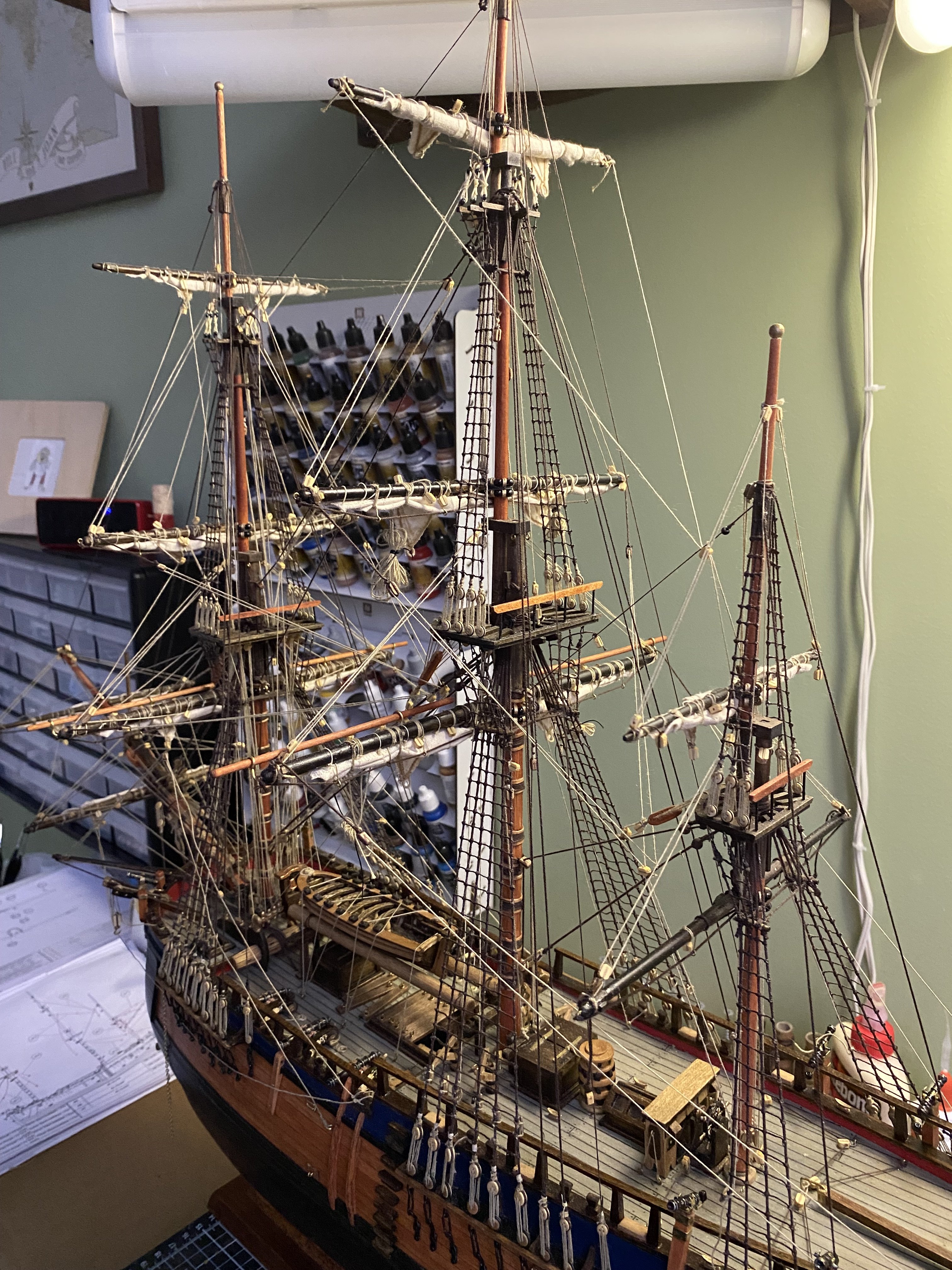
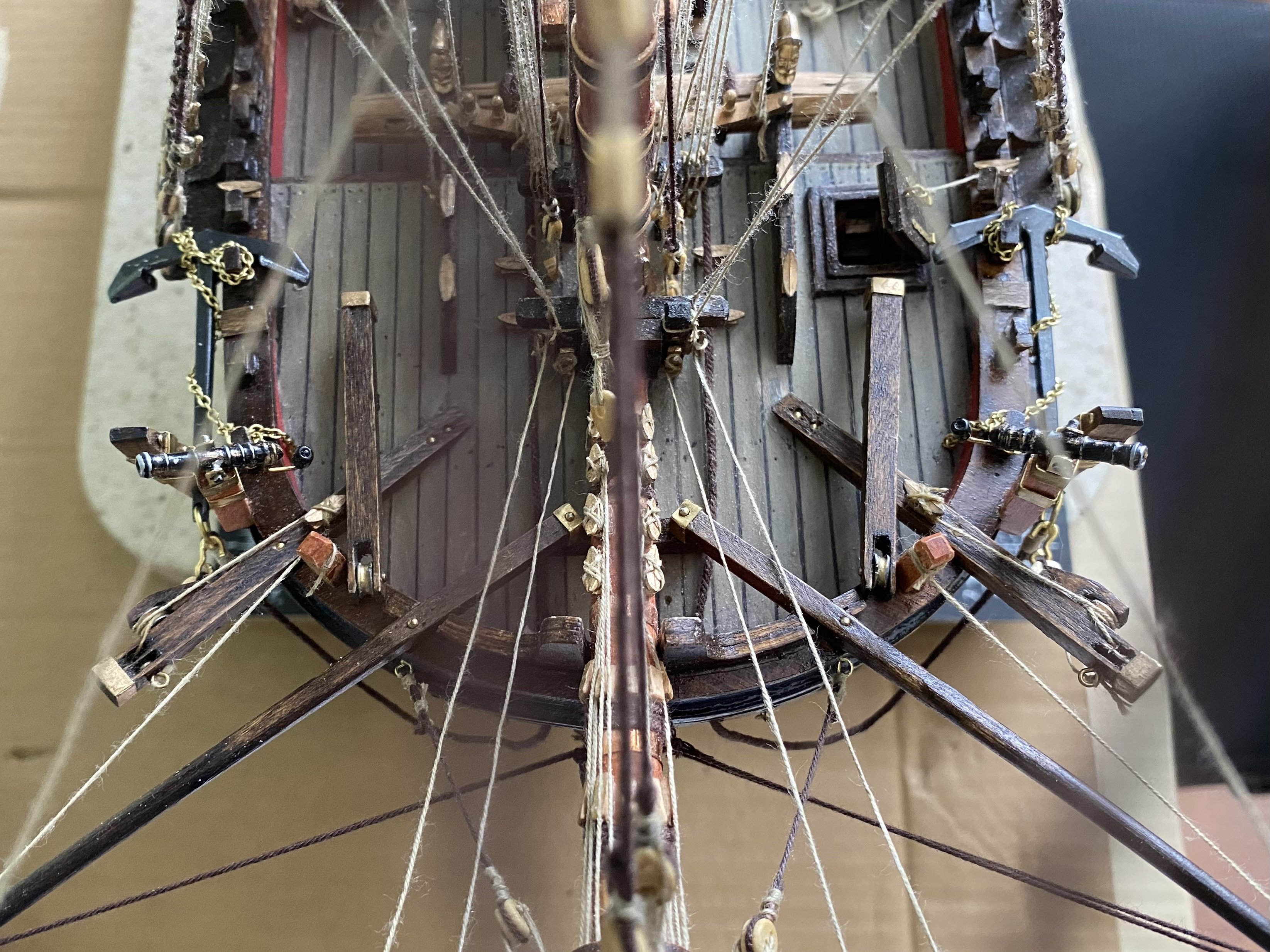
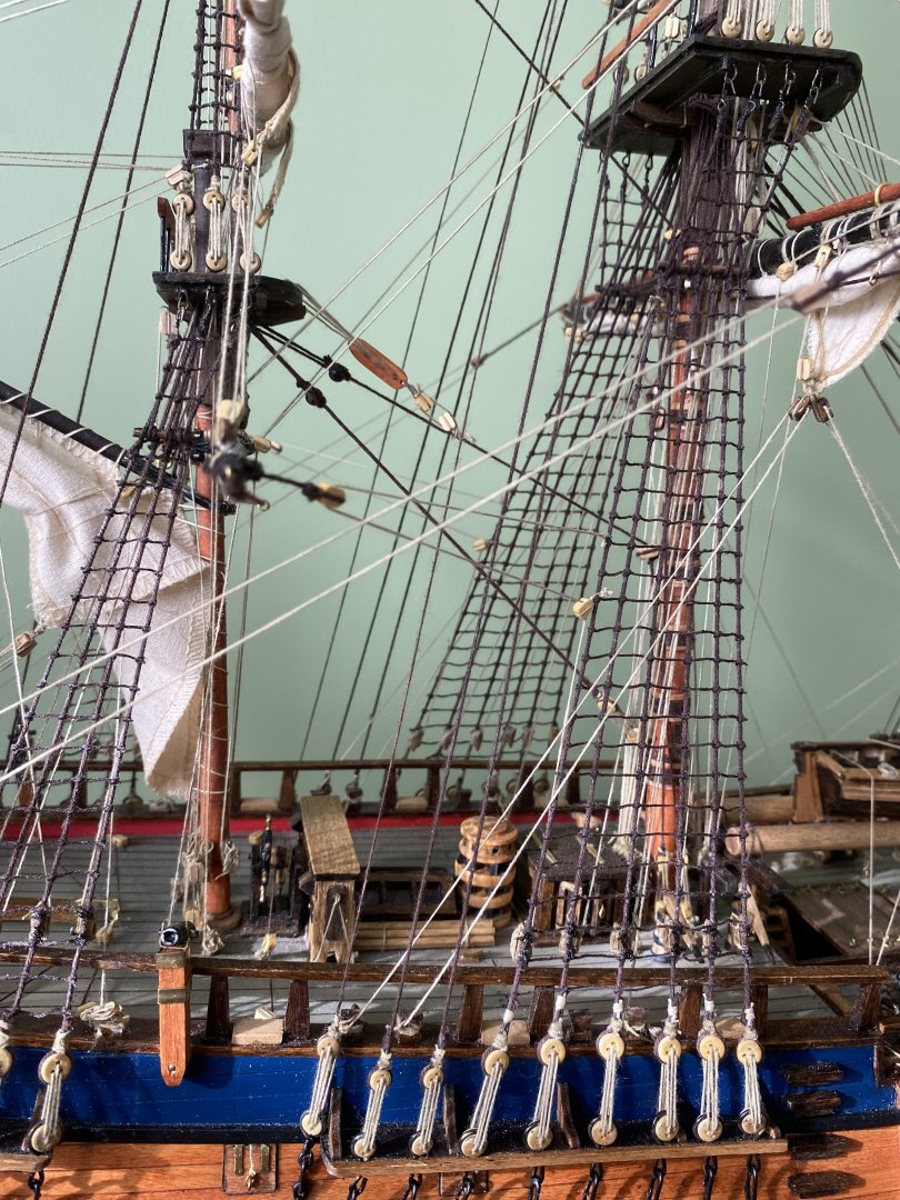
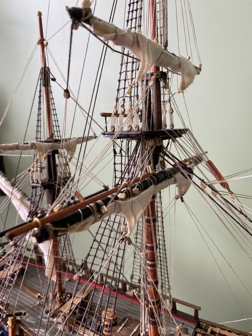
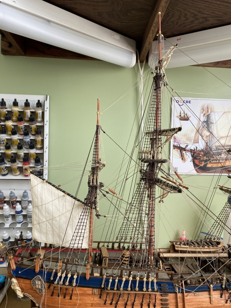
Gentlemen it has been a little over a week since my last update. I believe I am rounding the turn and heading for home (Kentucky Derby verbiage). Since my last post I have gotten the mizzen mast rigged and working on the mizzen course. The mizzen course will be furled when I am finished with rigging it. I still have a good deal of detail work to do like making a zillion coils to put at each of the belay points, additional ropes at the hatches on the sides, flag pole and flags, etc.


-
Hello Daniel my friend. So glad to have an update from you. I was concerned that you might be ill or just quit on your AV. The handmade net looks beautiful. Great job.
-
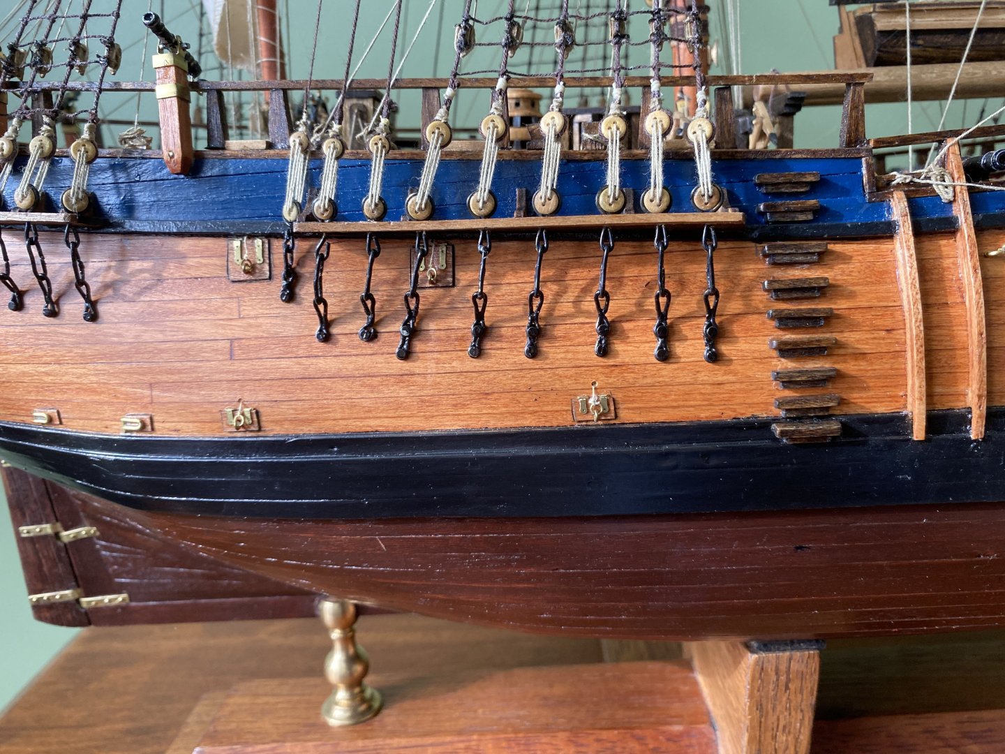
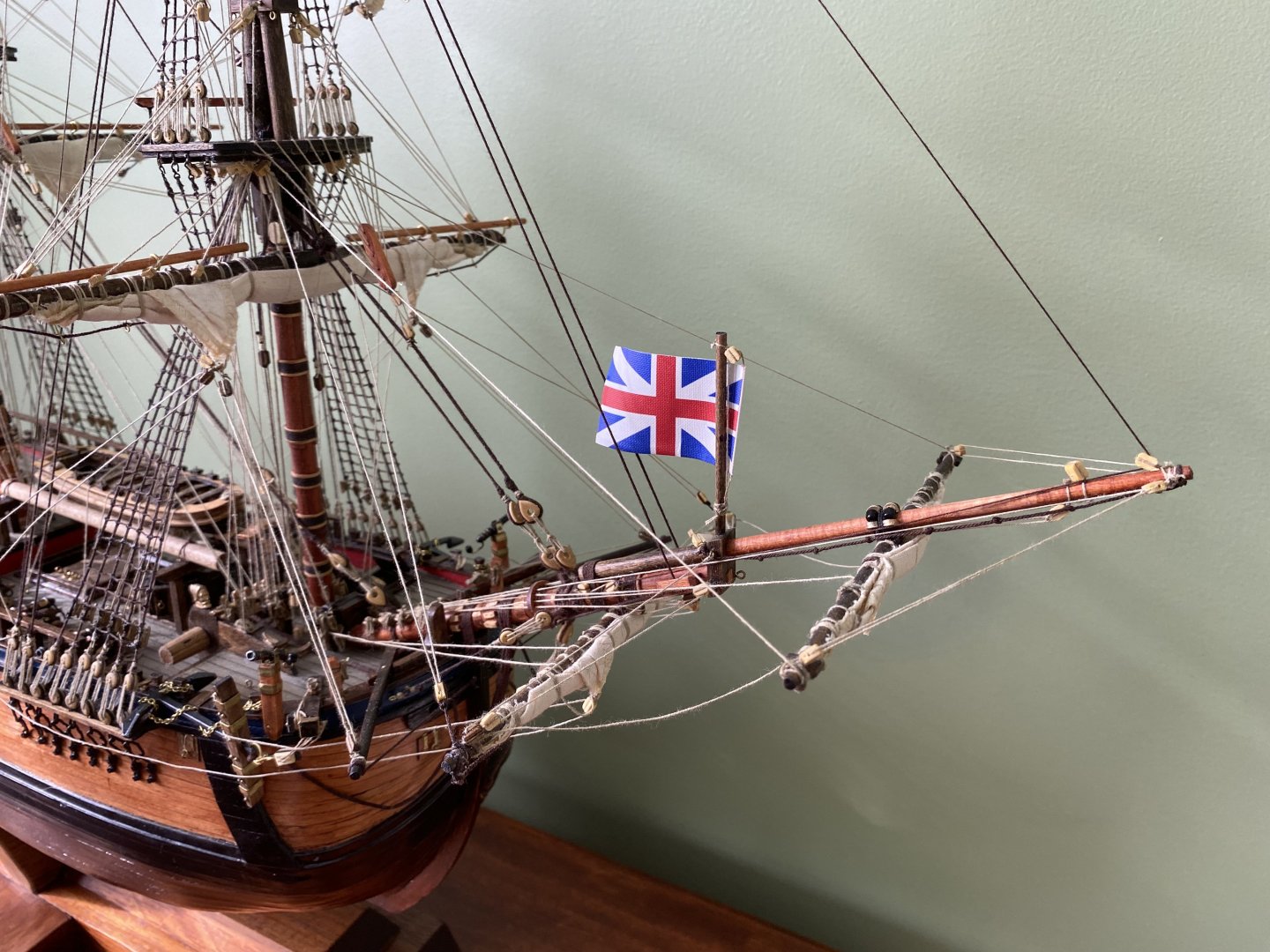
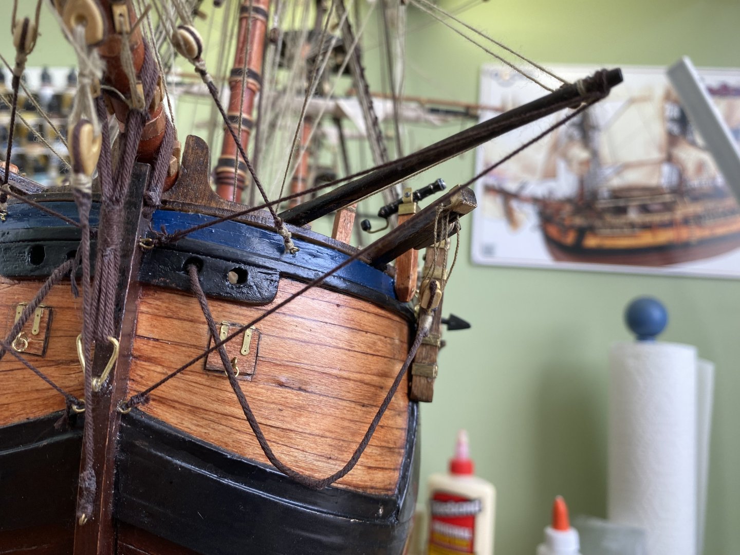
Lifts and braces the order of the day in the ship yard now that I have moved past the boomkins.


-
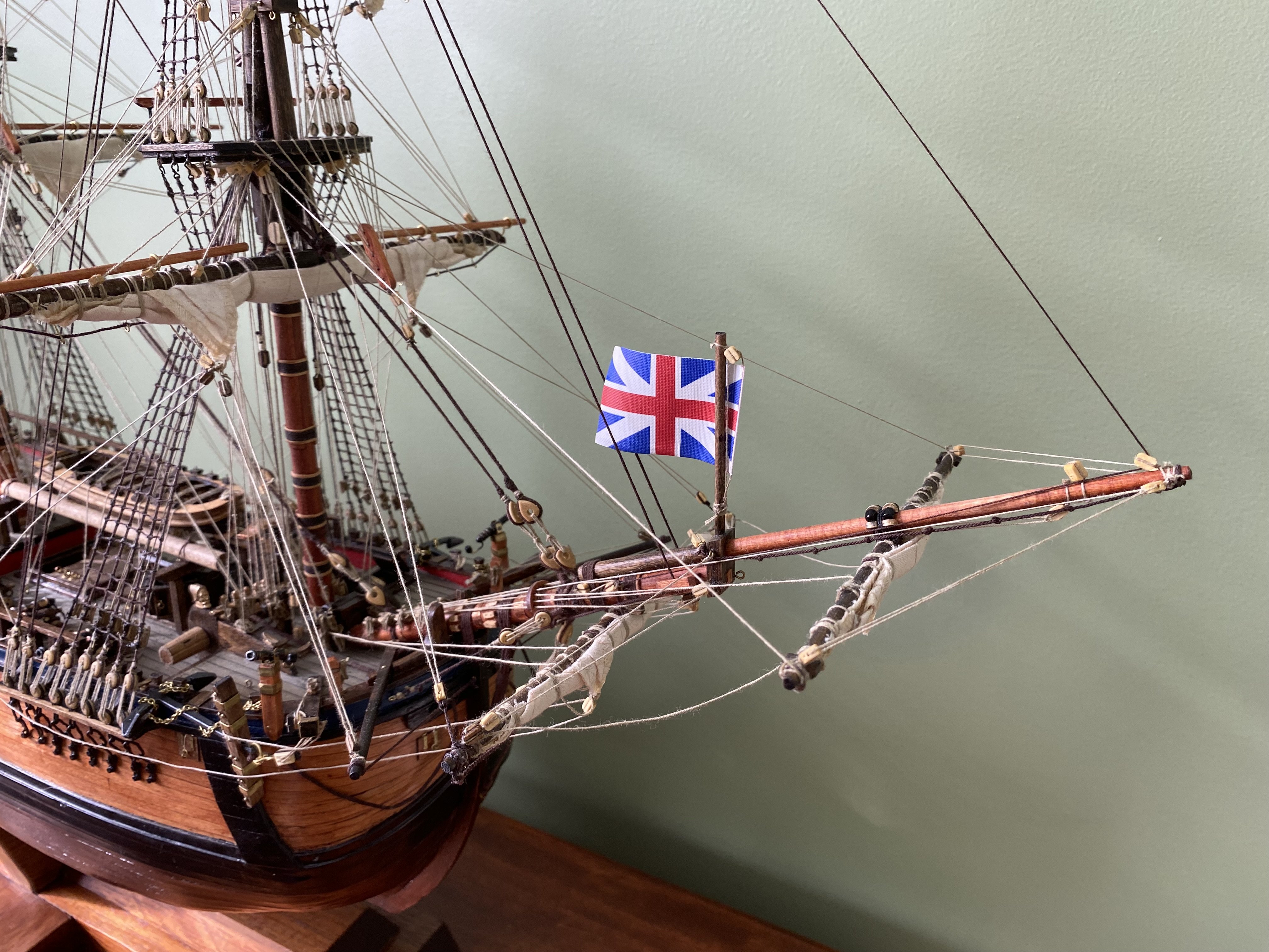
Oh no Allan you did not hijack my post. I started the discussion and appreciated all the input. What I eventually did was keep the boomkins and simply ran guys back to the ship above the howser hole. Now no guys are below that point. I am not even going to question the outer gammoning! 😀
-
That does seem to be the most practical solution. I will give a look at removing the boomkins. If I can’t without to much damage I think i will arrange some sort of satisfactory rigging and call it a day on this riddle
-
Good morning Marc. Welcome to this very intriguing conversation. I always say when the world seems to be going to the dogs it is good to have a cave we can get in, roll the stone in front, and just talk ship building!😊
-
Steve where did you attach the tacks from the fore course sail if you didn’t have the boomkins? I am still open to making changes with the guy(s)/shrouds. Not going to remove the boomkins. That would make for a bunch of woodwork repair.
-
Thanks Allan. I will see how that looks.
-
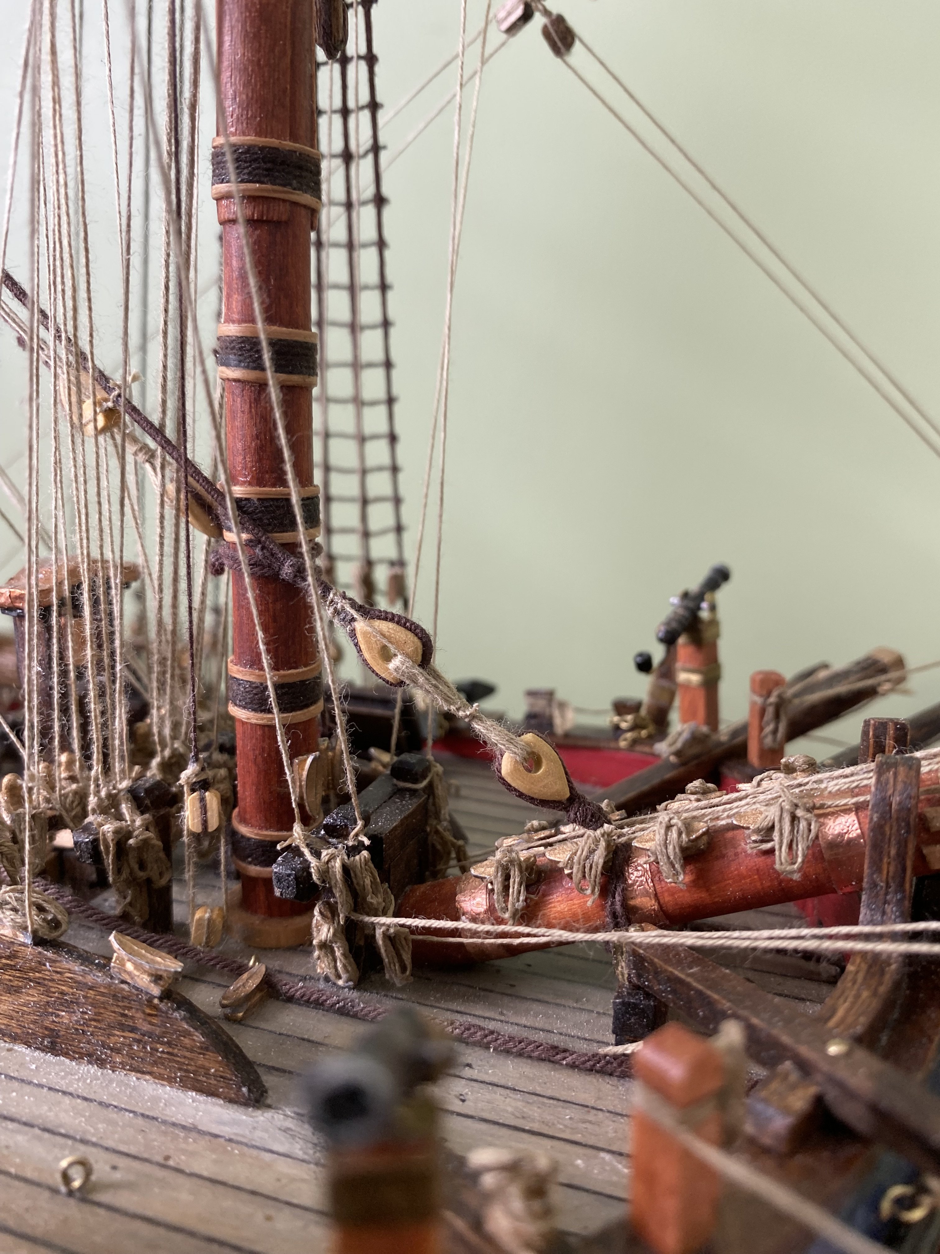
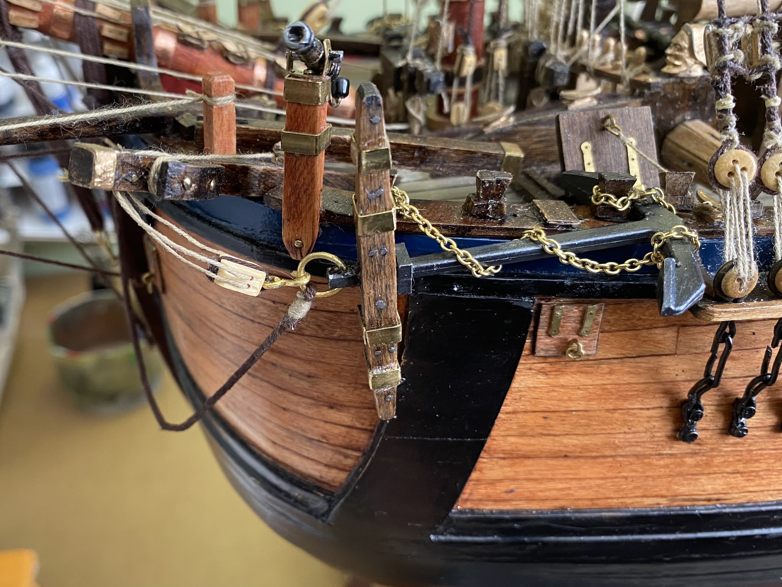
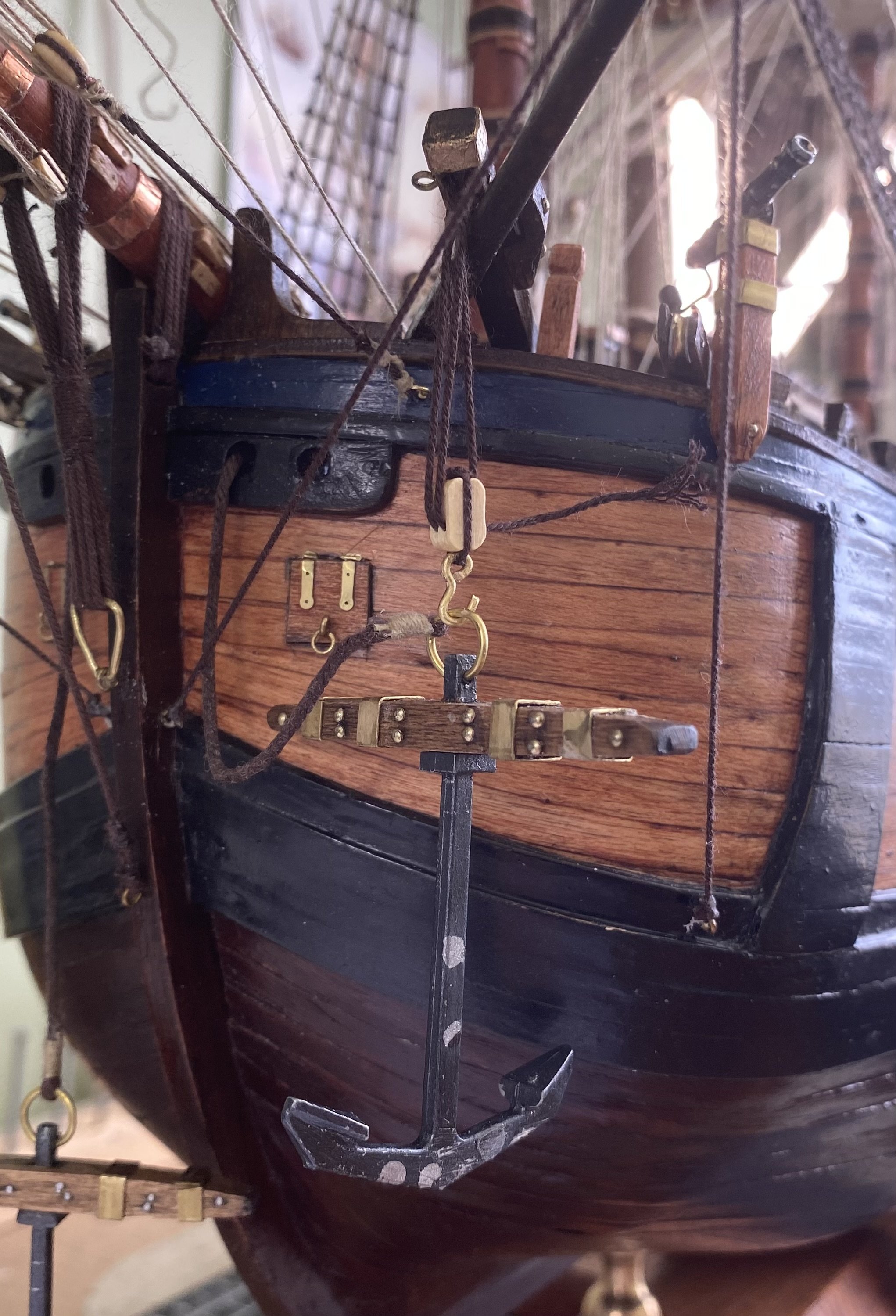
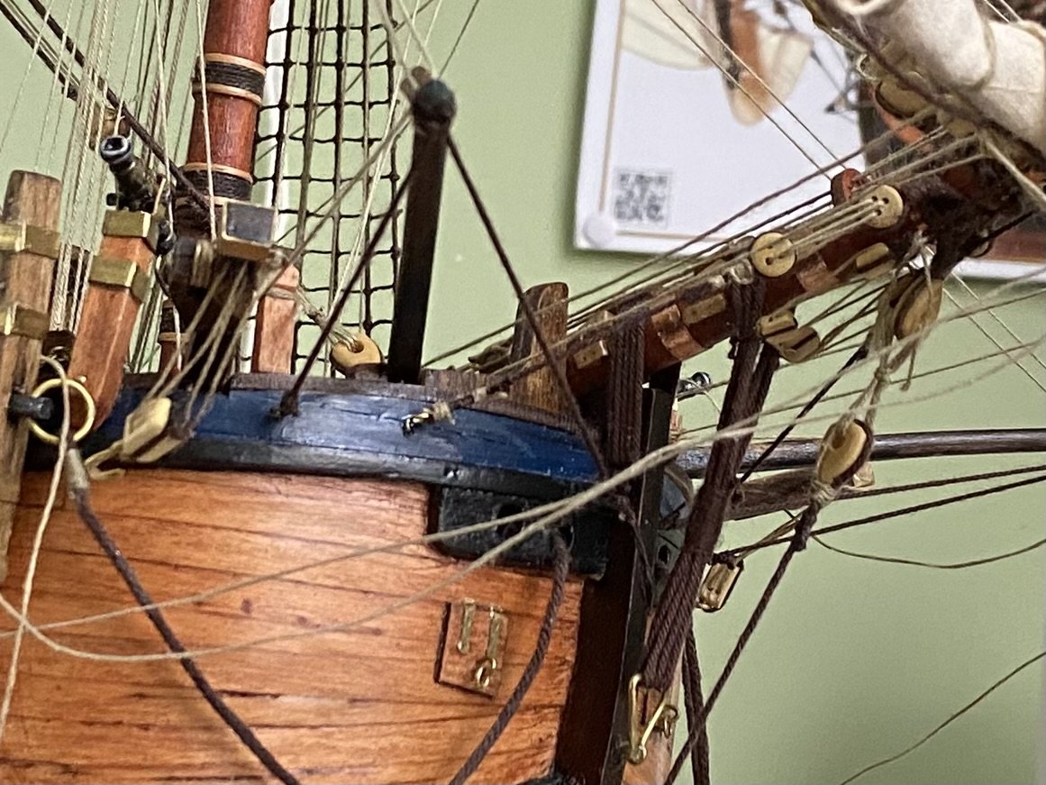
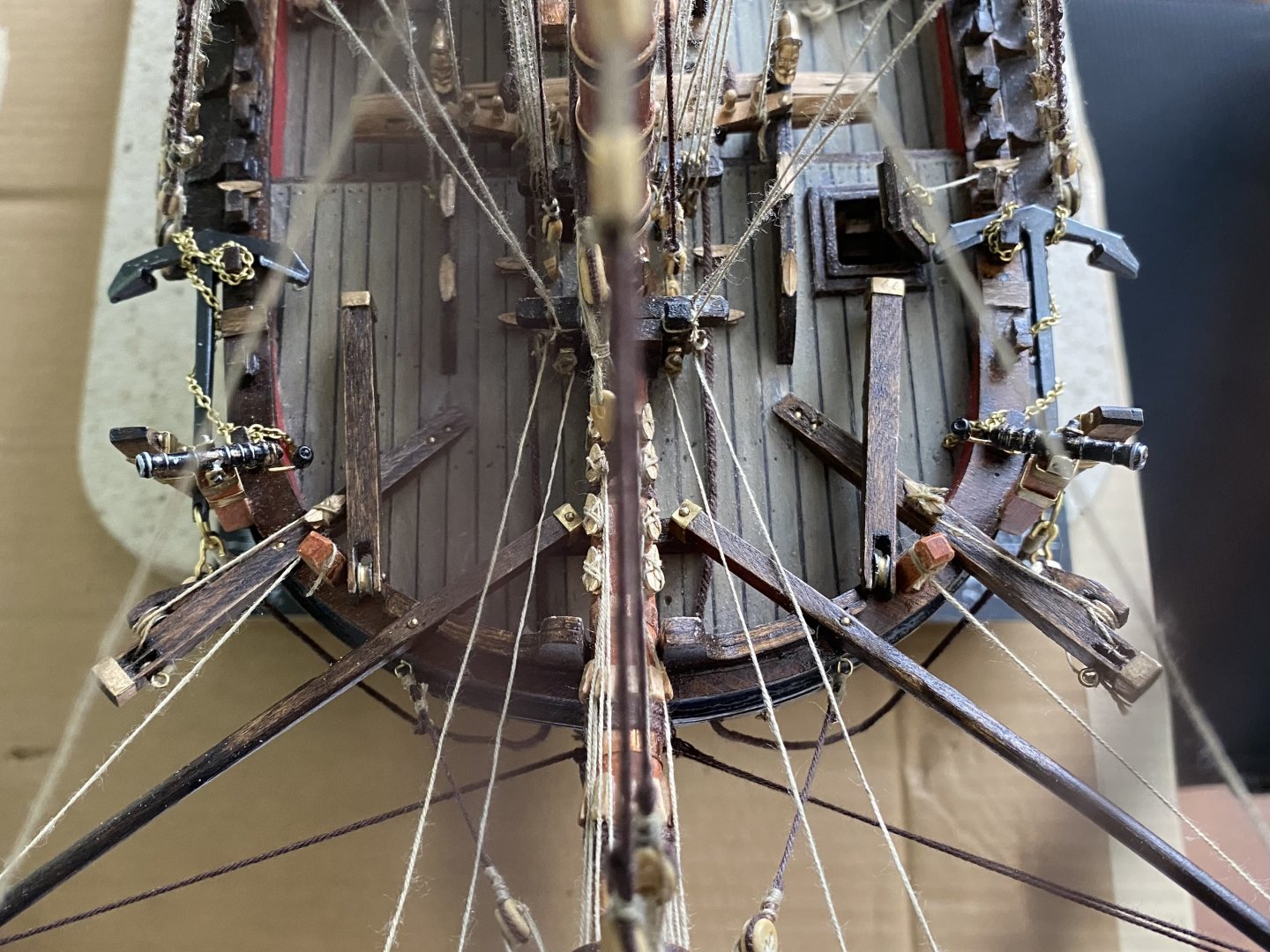
Gentlemen the fix is in. Moved both boomkin shrouds over to the knee. Also repositioned the cathead which makes the whole system work and look better. Now only thing remaining is deciding for sure where I want to reposition the fish davits. I currently have them where I left one end bolted to the deck by a ring bolt which permits rotating it inboard and outboard. I added an additional piece of wood where it would rest on the bulwark when in use. The additional oiece of wood is to protect the top of the bulwark. I currently rotated the davits forward and lay next to the cathead where I could lash them if I decide this is what I want.


-
Thanks guys. You have given me a path forward to solve this riddle. Will keep you informed. I think I will move the boomkins like the illustration above and also the shrouds as you show Allan. Wish me luck. Will require a bit of wood repair work but not to difficult. Bill
-
Thanks Trevor. I will give your suggestion a study to see how it might solve our riddle.
-
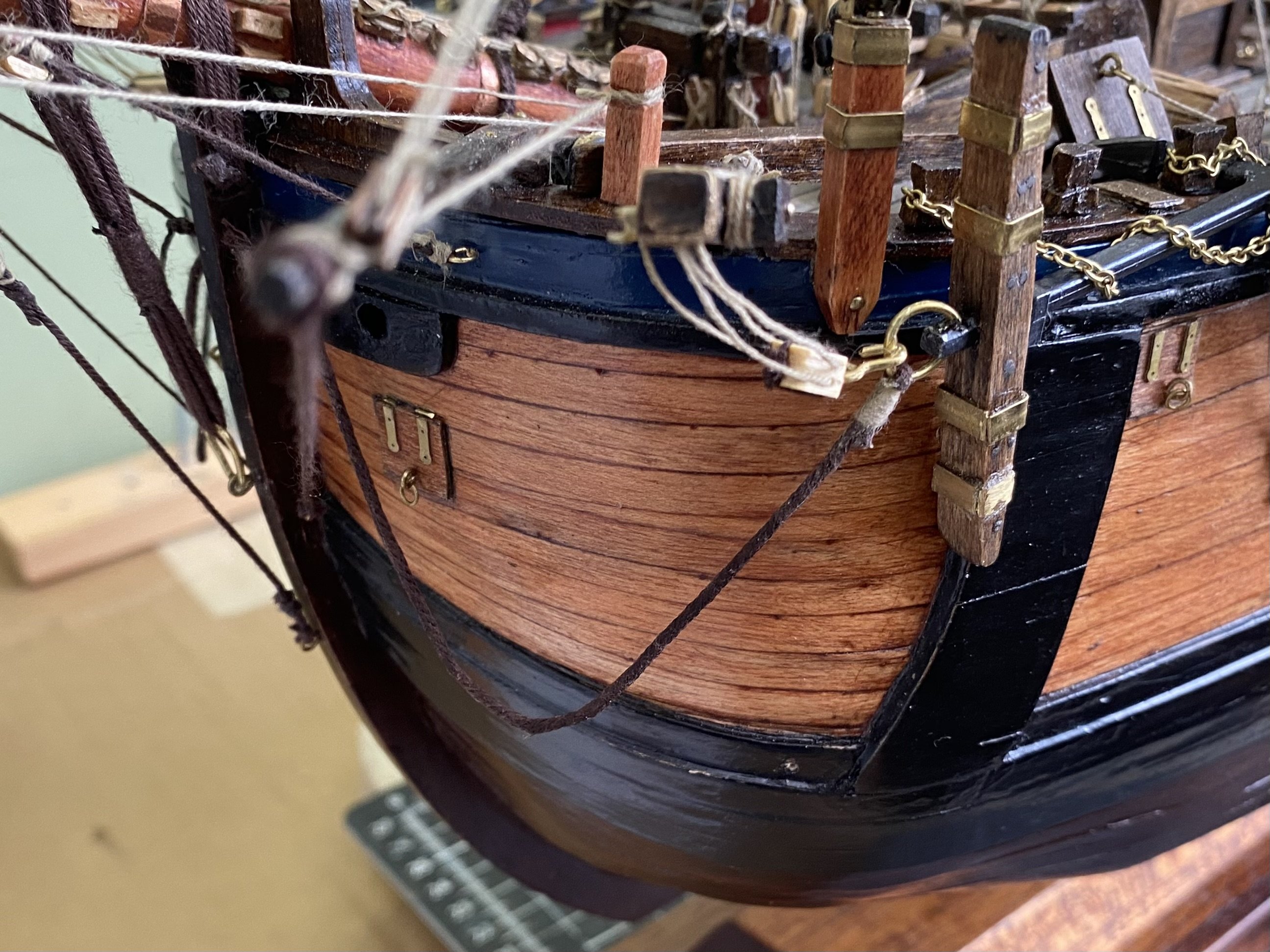
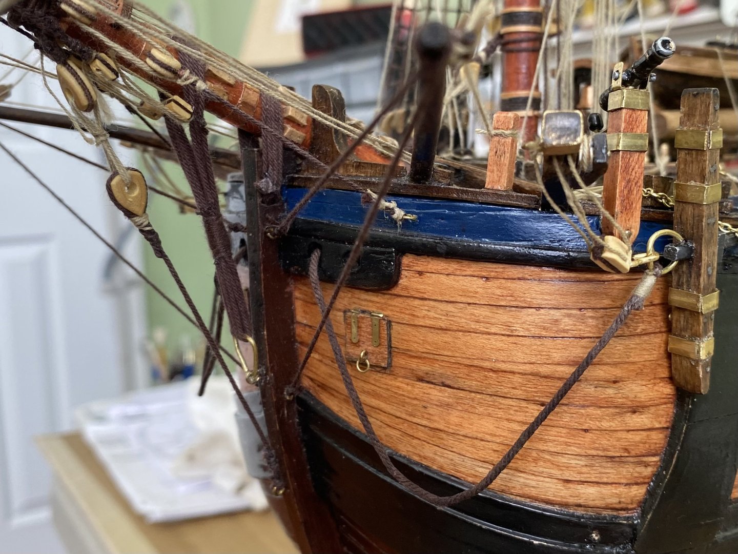
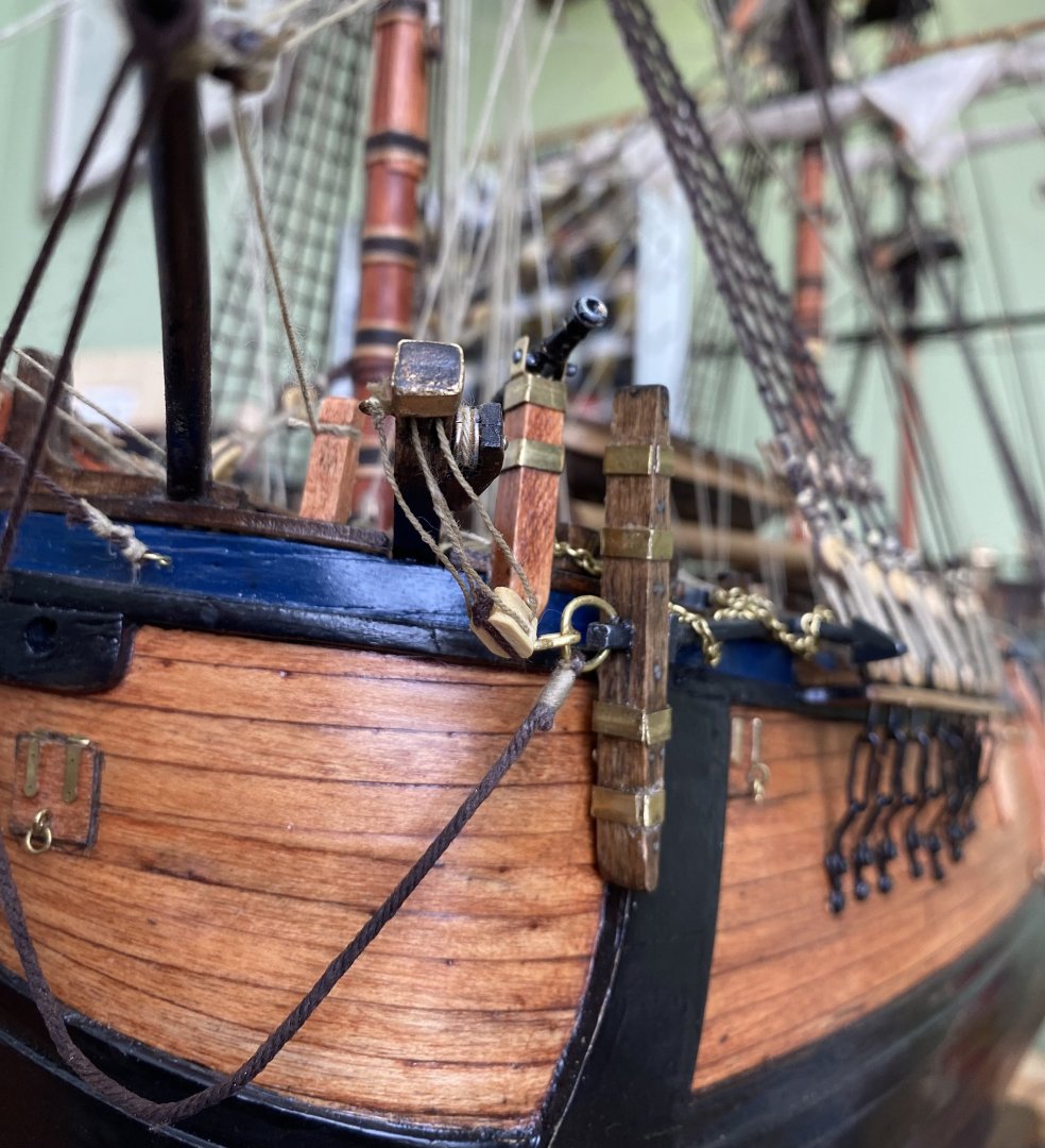
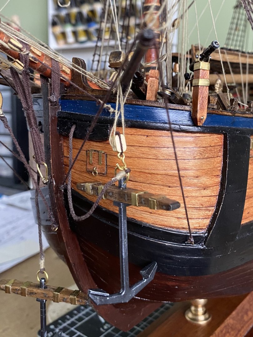
Allan this photo is from the same point of view as the one you posted of your build except mine is from the port side. I am trying to see what I have different from your’s that would solve the riddle. One thing I see is my rope from the anchor to the howser hole is shorter. Don’t know that would make a difference. think I am going to move further toward the stern of the ship working on rigging of the main mast while I continue to study and seek help on this bumpkin shroud/cathead anchor riddle. Surly someone out there has the answer. For now the bow of my model will just look in disarray. I could just say the heck with it and rig it as OcCre instructs (who would really know or care) but as we have discovered it would not be correct.
-
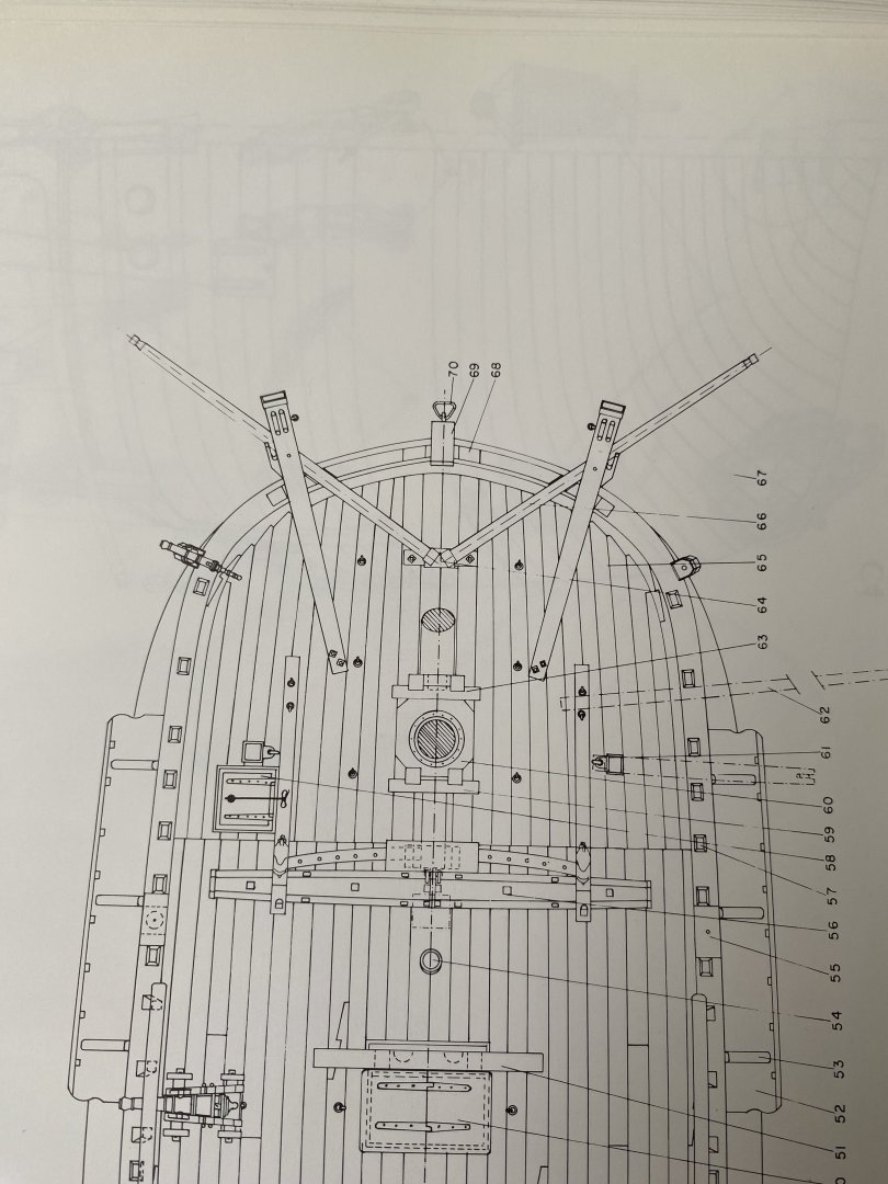
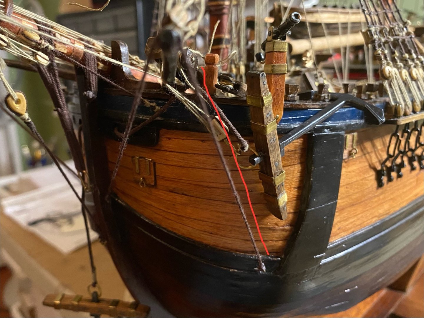
This is the drawing in the Anatomy of the Ship book by Marquardt. Showing the catheads inside the bumpkins. How would this have been possible for the anchor and rope not to have interfered with the bumpkin shrouds. Interesting
-
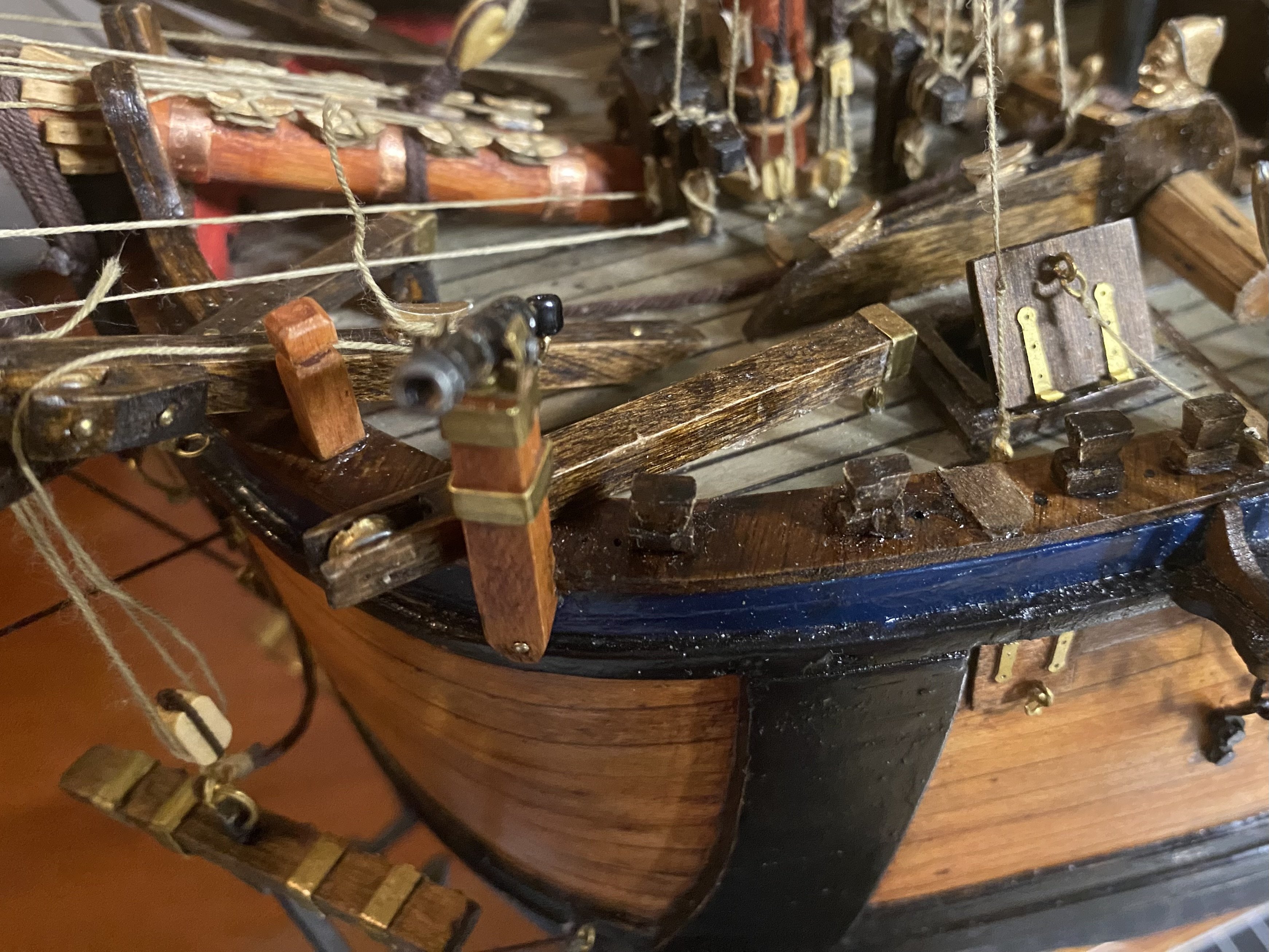
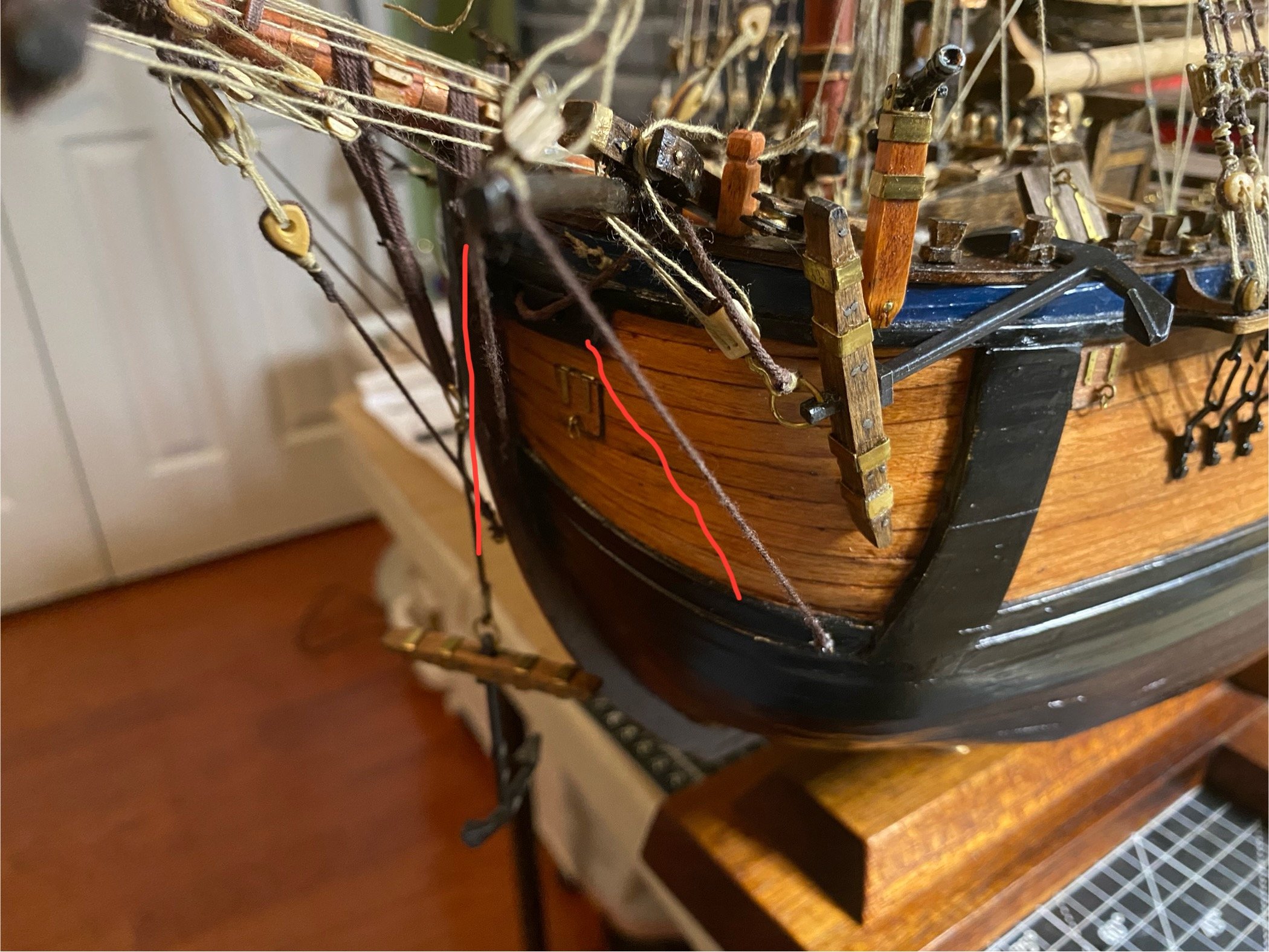
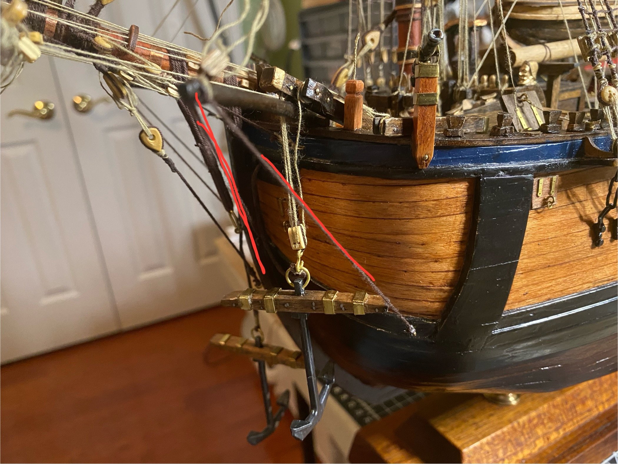
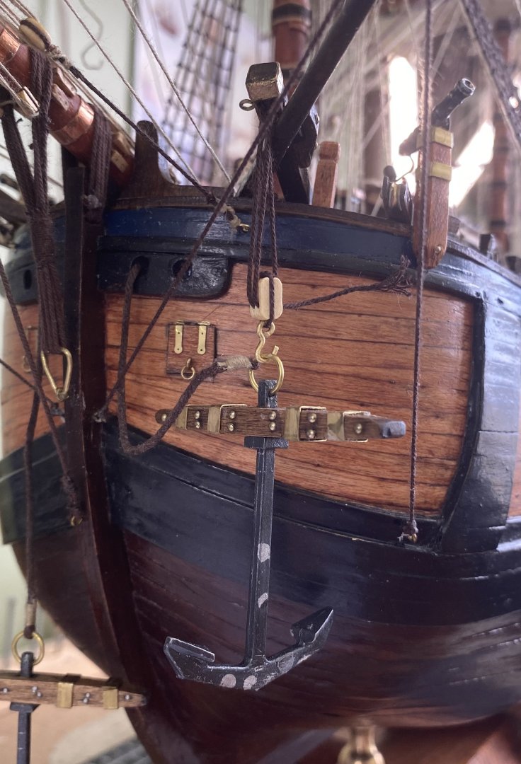
OK Trevor and Allan you guys have given me good advice s far. I tinkered with the anchor situation good part f the day and have some progress, but also a head scratcher. I attached a few photos. I think I can successfully move the fish davits inboard on the forecastle. The end is in a ring that pivots. I basically lifted loose end up and rotated it forward on the bow out of the way where I can lash it to a timber. In this configuration the crew could raise the loose end and pivot it back to the side to use. It is an idea. I also rigged the anchor to the cathead with a double block with a hook. My issue here that I need additional thought on is the cathead is right beside the bumpkin. The bumpkin shrouds go down to points on the hull. See red lines in photos. If the anchor would be pulled up to the side of the bow it comes in contact with the bumpkin shroud. What might I have wrong?


-
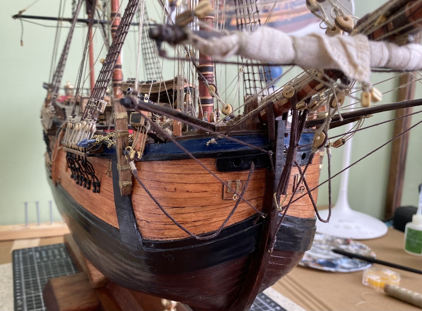
Thanks gentlemen. Sorry to have belabored such a small detail, but so appreciate your help. I am going to remove both fish davits, repair the area where it was, and find a convenient place to stow just one. Will show update when completed. Thanks again Bill
-
Ok great. My curiosity kenchington was, as you stated above, the fish davits were stowed away when not actually in use. alpayed I am leaving the anchors at the bow. So my question was once the anchors were raised with the help of the fish davits and fixed in position was the fish davit then stowed away? From what you guys are saying I think it was. So if I have my anchors on the bow then the fish davits should be stowed away not sticking out as mine are now. I need to remove them and stow on deck somewhere.
-
So Trevor I guess the easiest thing would be just to stow them on deck maybe. However I think I am confused. Are the fish davits just used to hoist the anchor and then stowed away once the anchor is locked in the weighed position or are they part of the weighed setup? Are they still helping to support the anchor the entire time it is secured on the side of the ship?
-
Thanks Trevor. You have been extremely helpful.