

Rodolfo Bigoni
-
Posts
102 -
Joined
-
Last visited
Content Type
Profiles
Forums
Gallery
Events
Posts posted by Rodolfo Bigoni
-
-
-
Hi Steven,
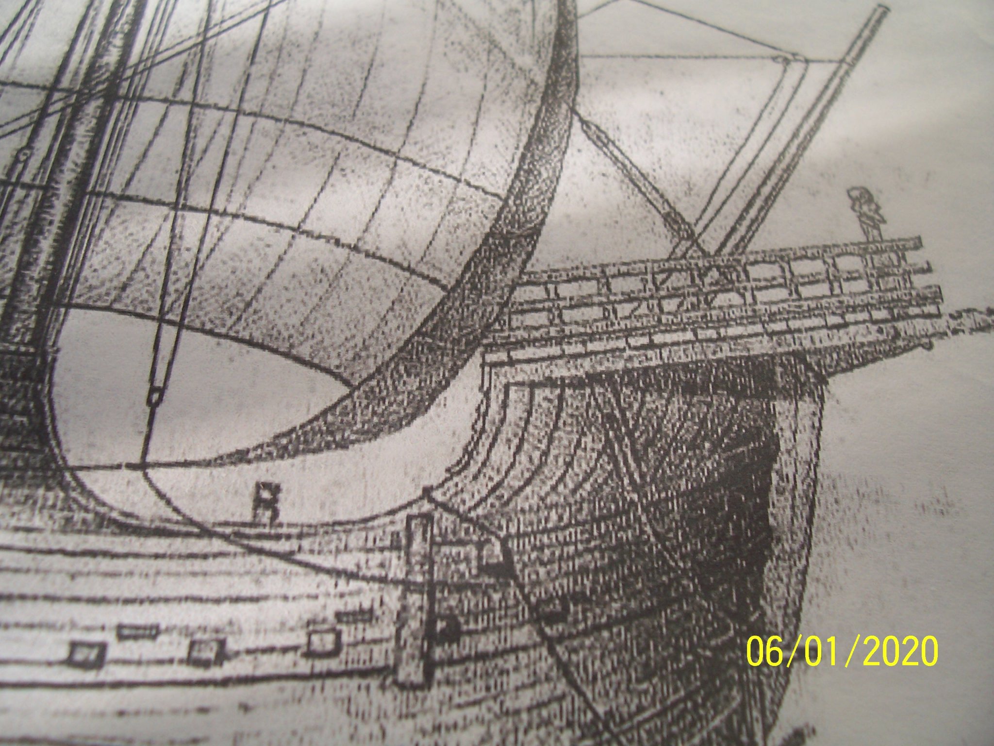
I've already found it in Pinterest:
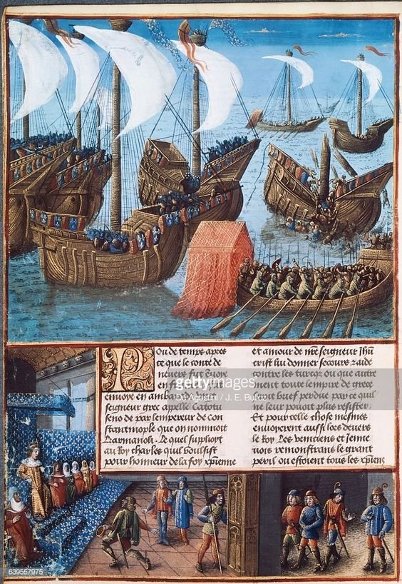
"Departure of the fleet of Marshal Jean II Meingre known as Boucicaut in 1399, miniature from the Chronicles by Enguerrand de Monstrelet, France, 15th century."
Hoping I've been useful,
Rodolfo
-
Hi Steven,
unfortunately (even before buying the kit) I've collected tons of pictures regarding medieval ships, only for doing better the work. At the beginning I never thought I would have to write a WIP and therefore I neglected the sources (usually WIKIPEDIA, PINTEREST and recently Modellismo.net in Italy, but also a couple of DVD having very old books, besides studies, thesis and so on).
But now I am trying to recover the missing information and if/when I'll find it, certainly I will communicate it to you.
Rodolfo
-
Thanks Steven,
that technique has been suggested inside the instructions of the manufacturer "AMATI"; another technique would be to cut the whole mainrail after copying them on walnut plywood or larger strip (because they aren't present in the box).
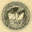
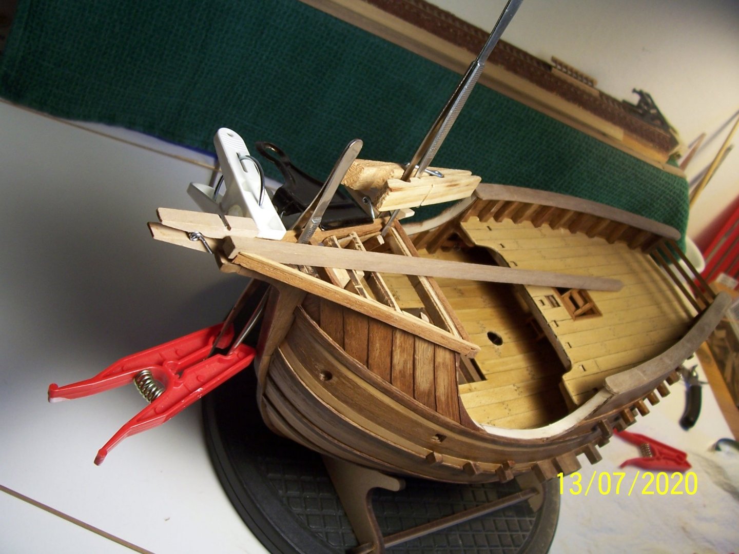
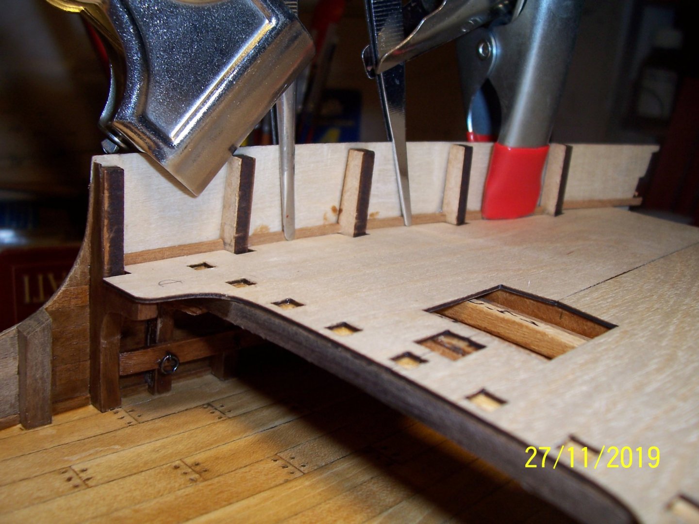
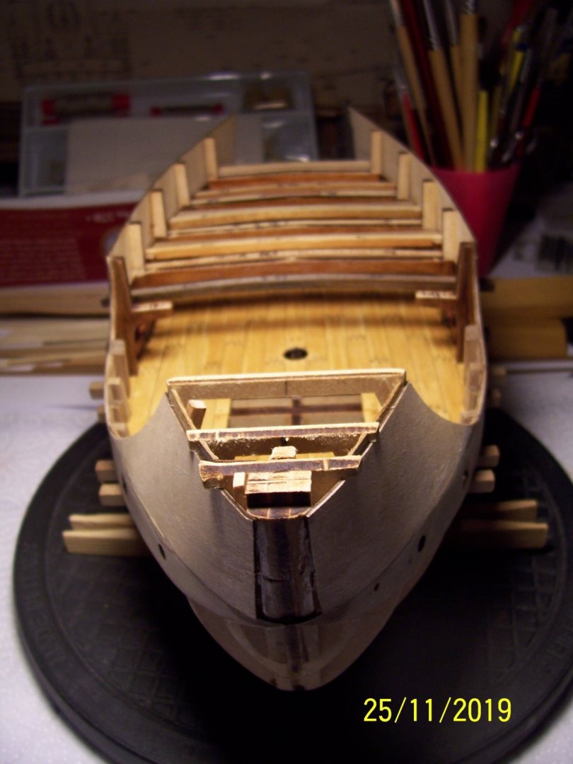
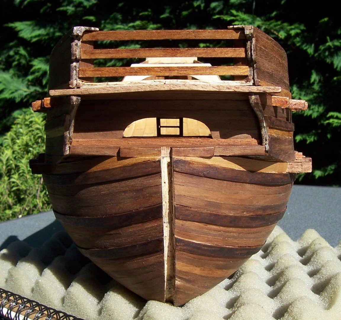
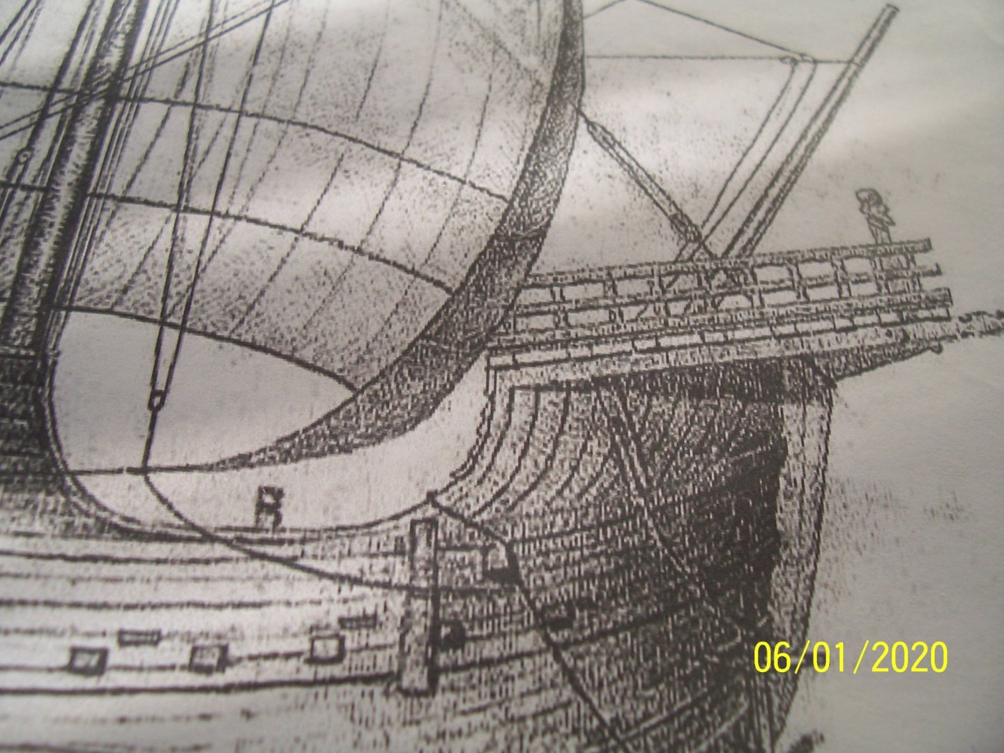
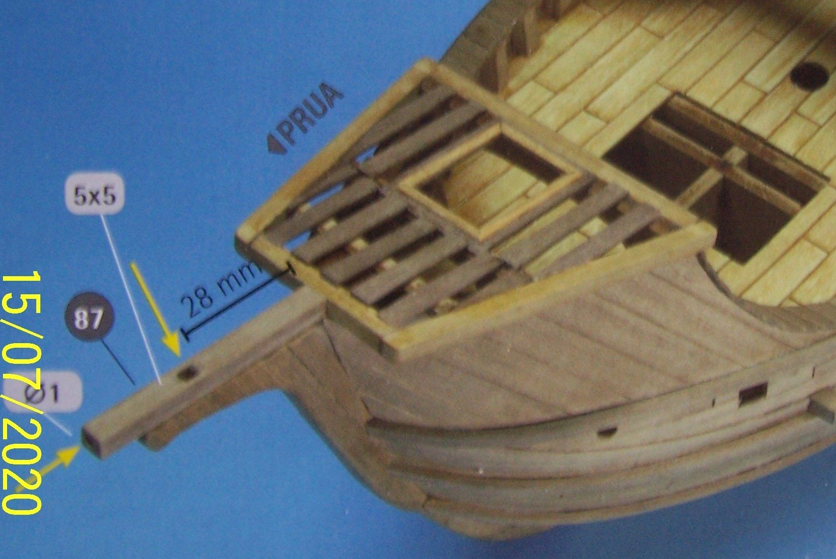
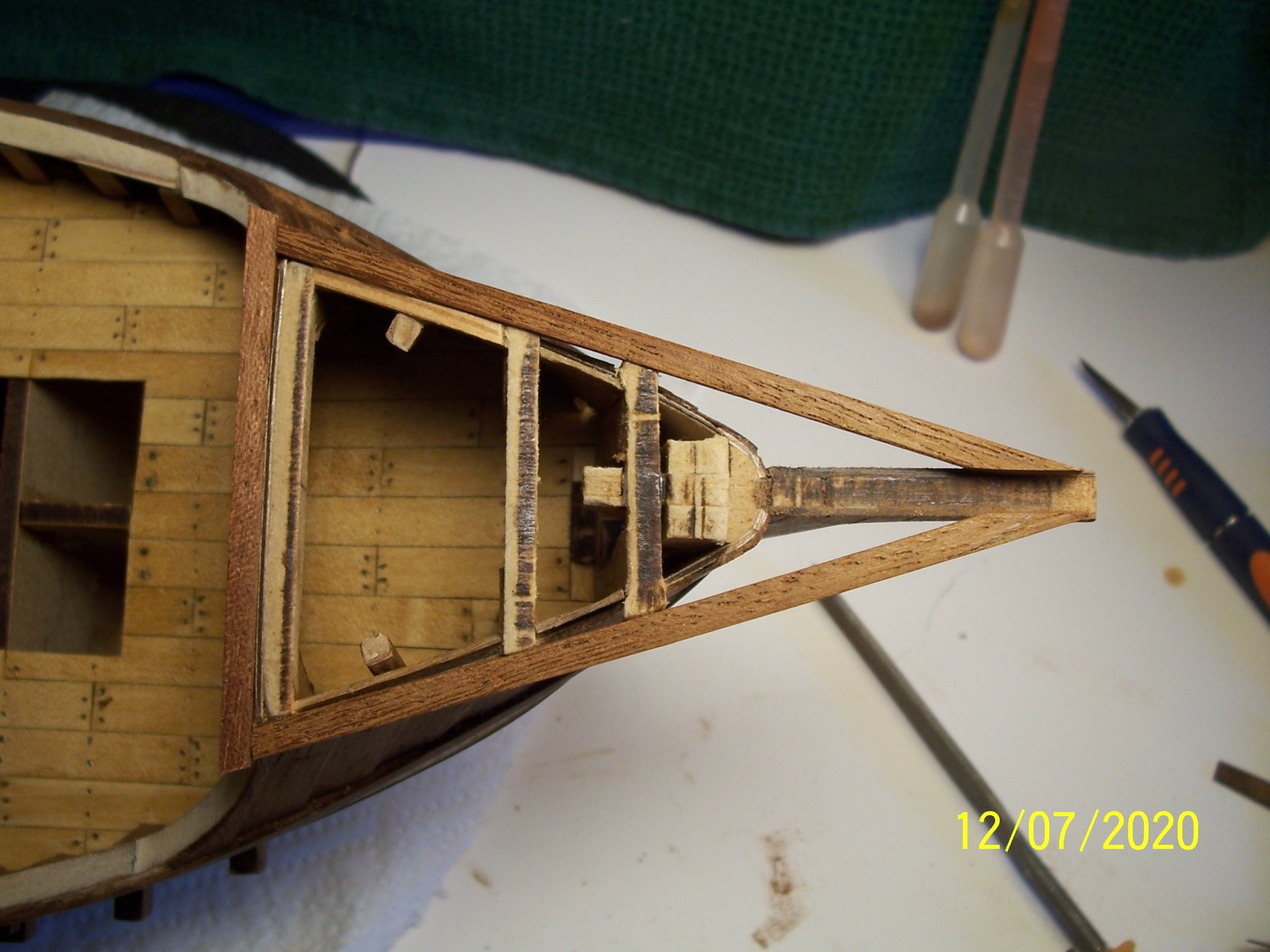
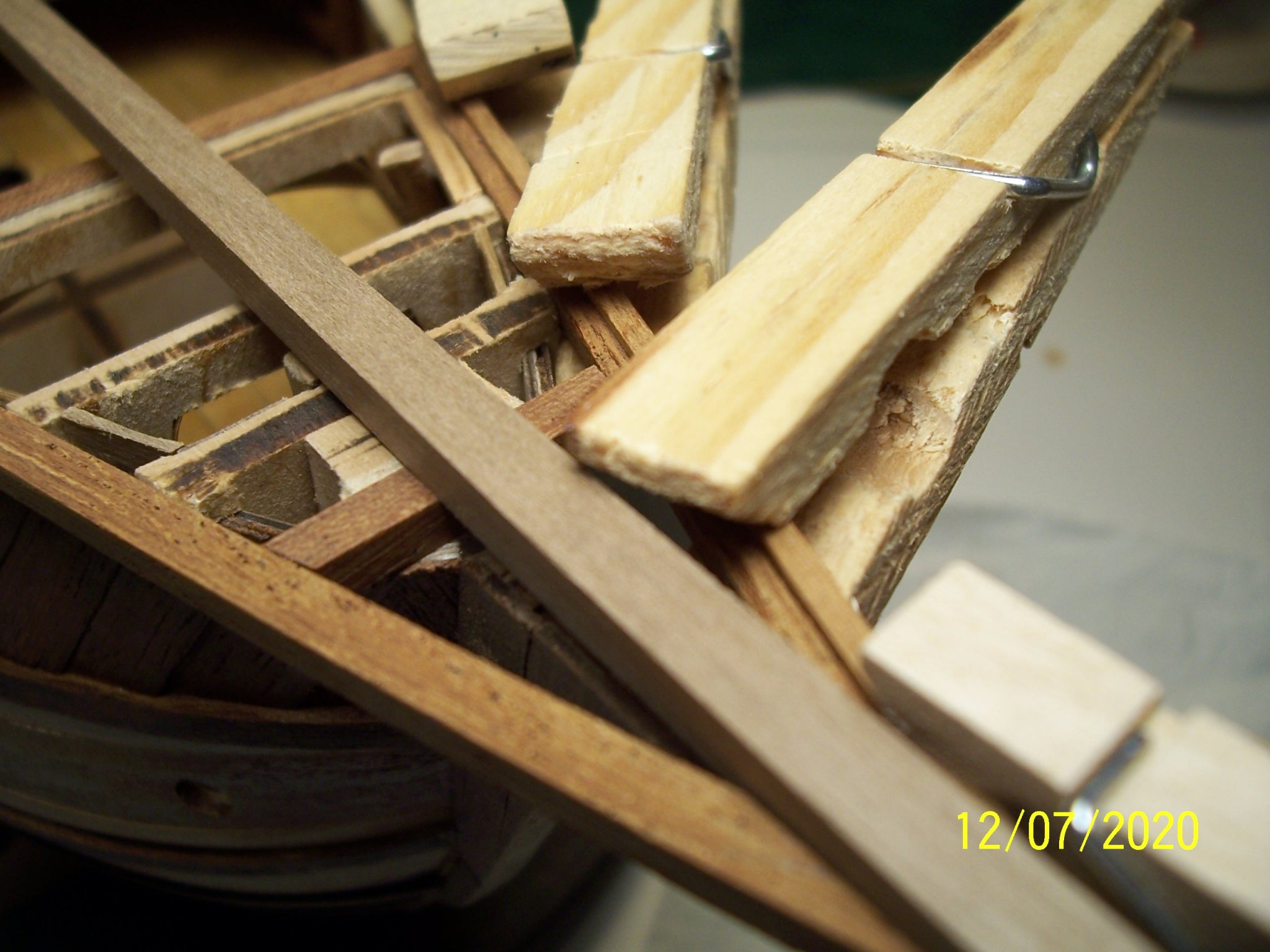
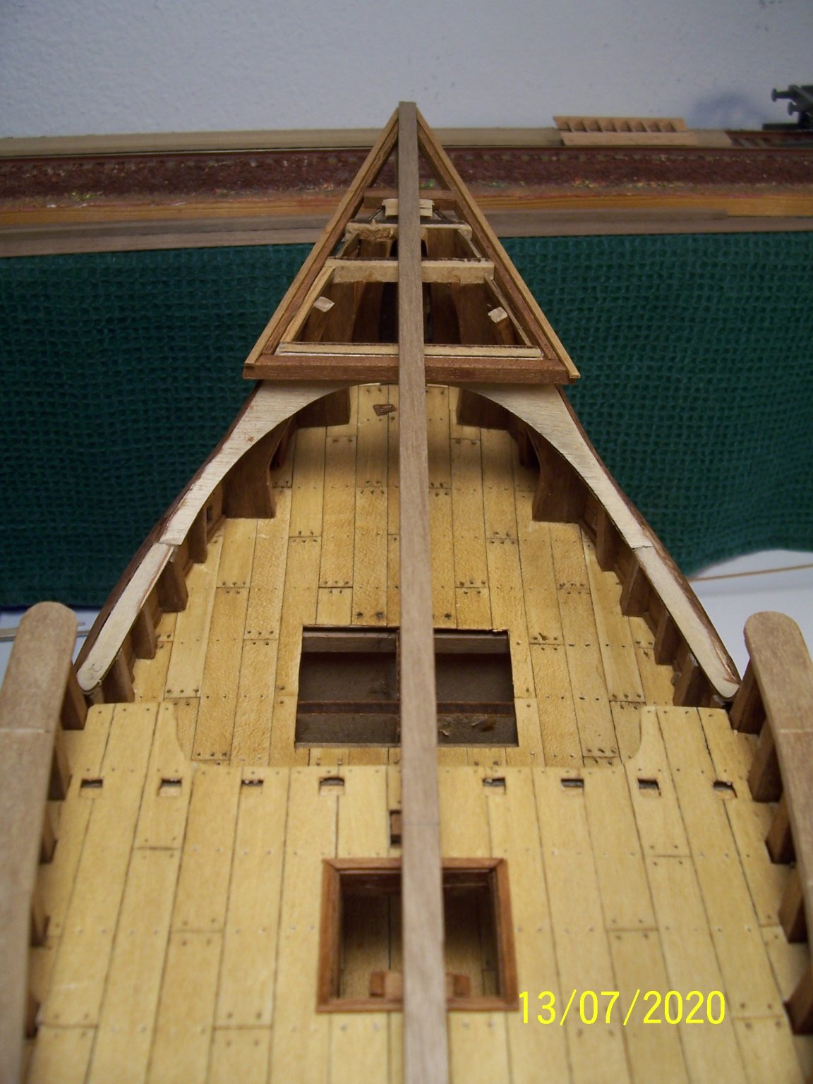
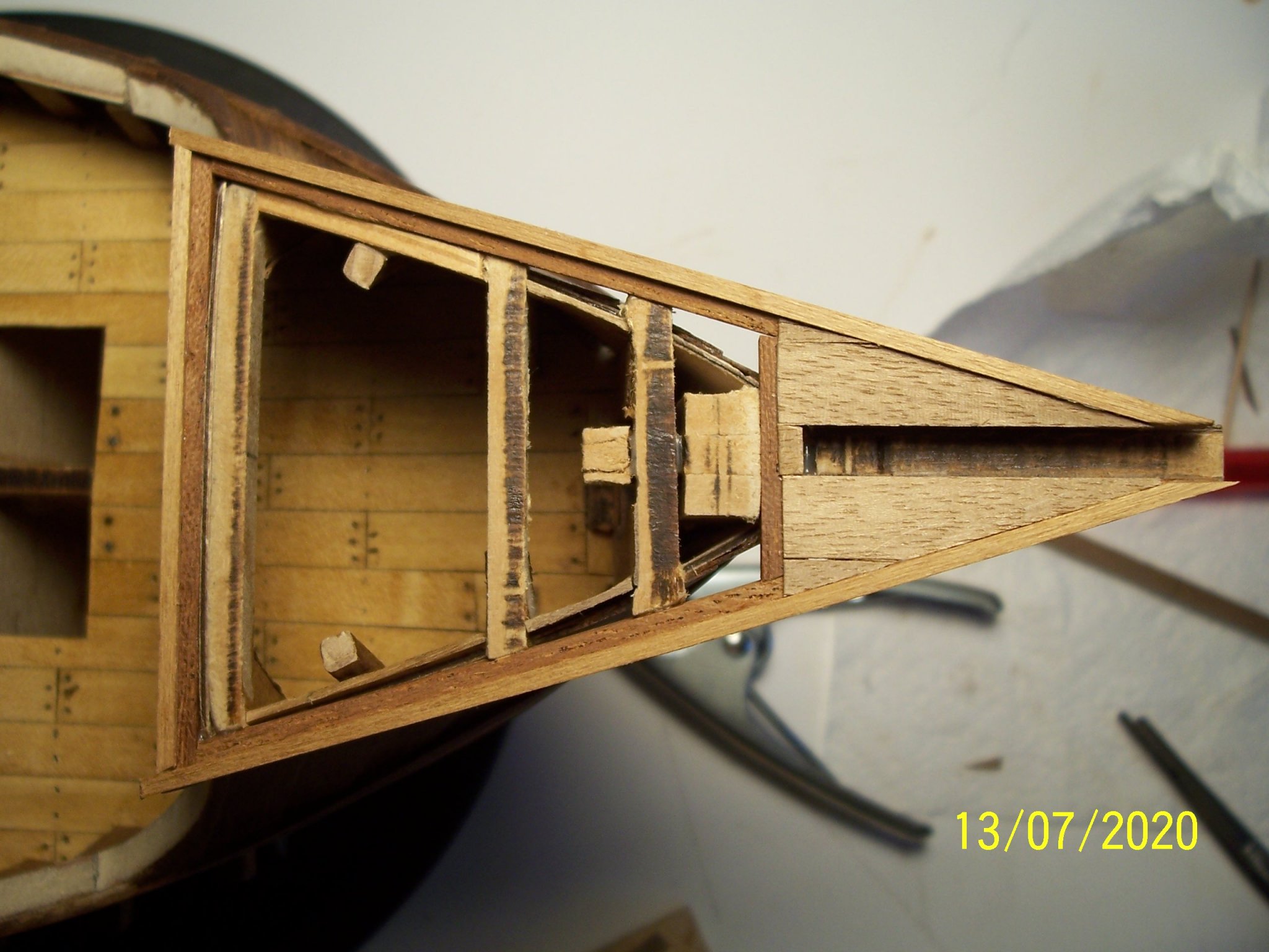
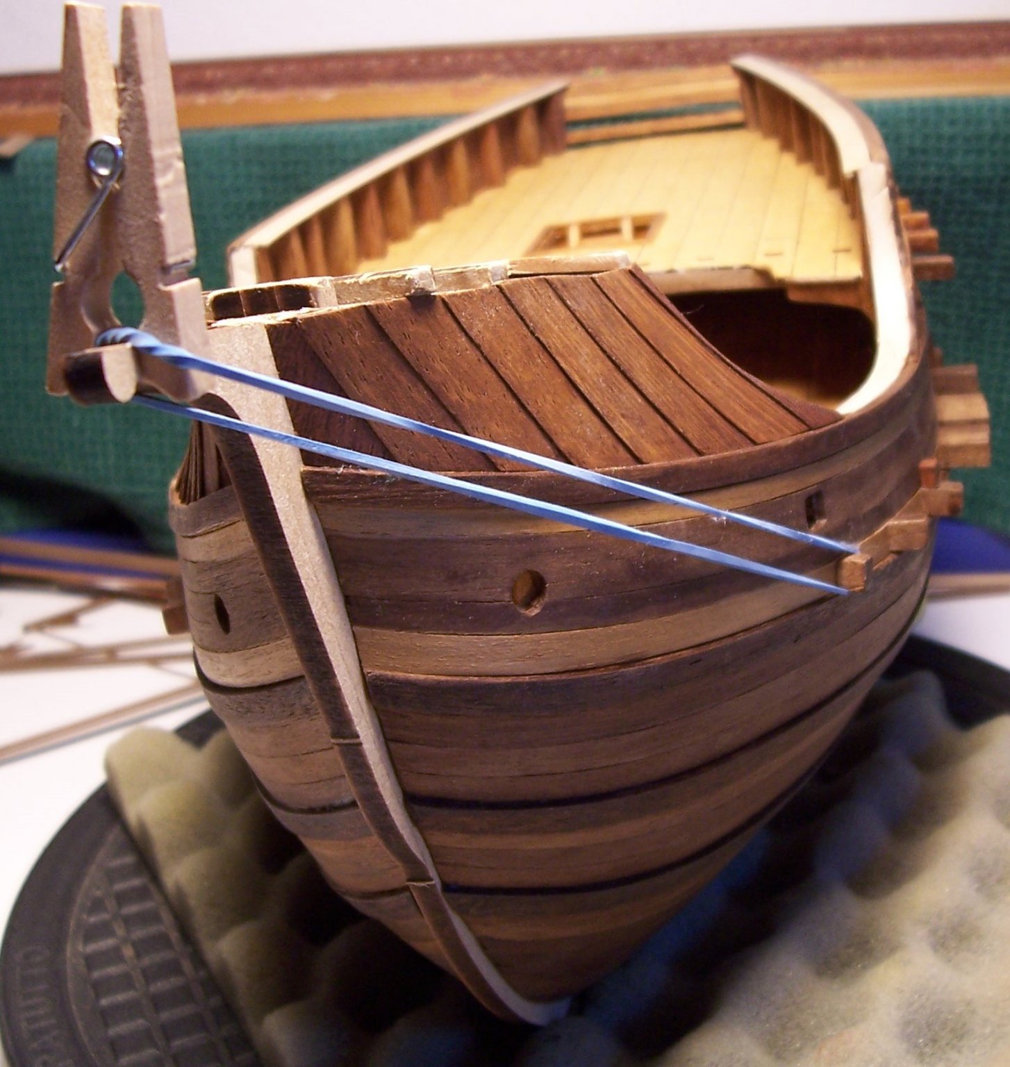
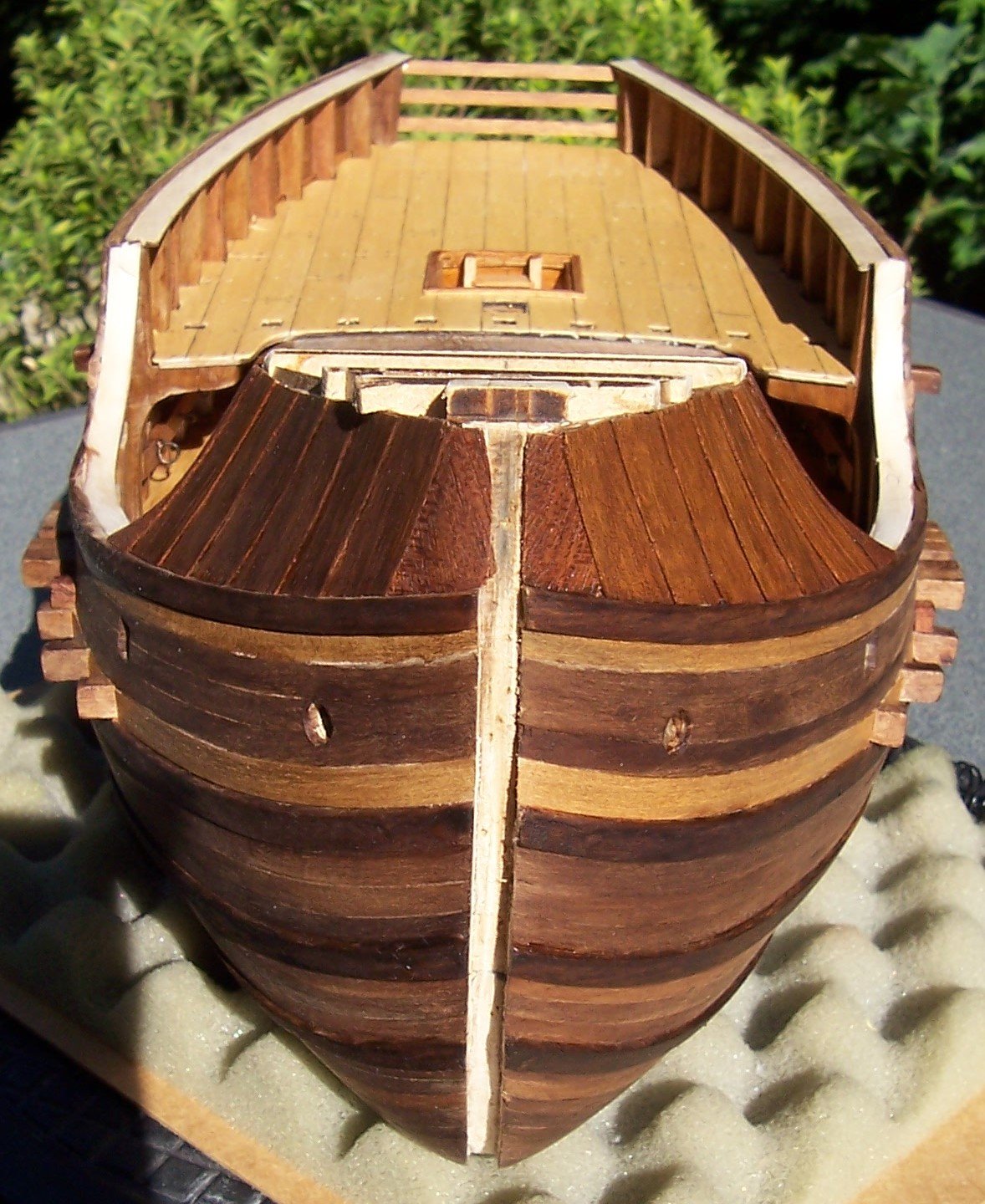
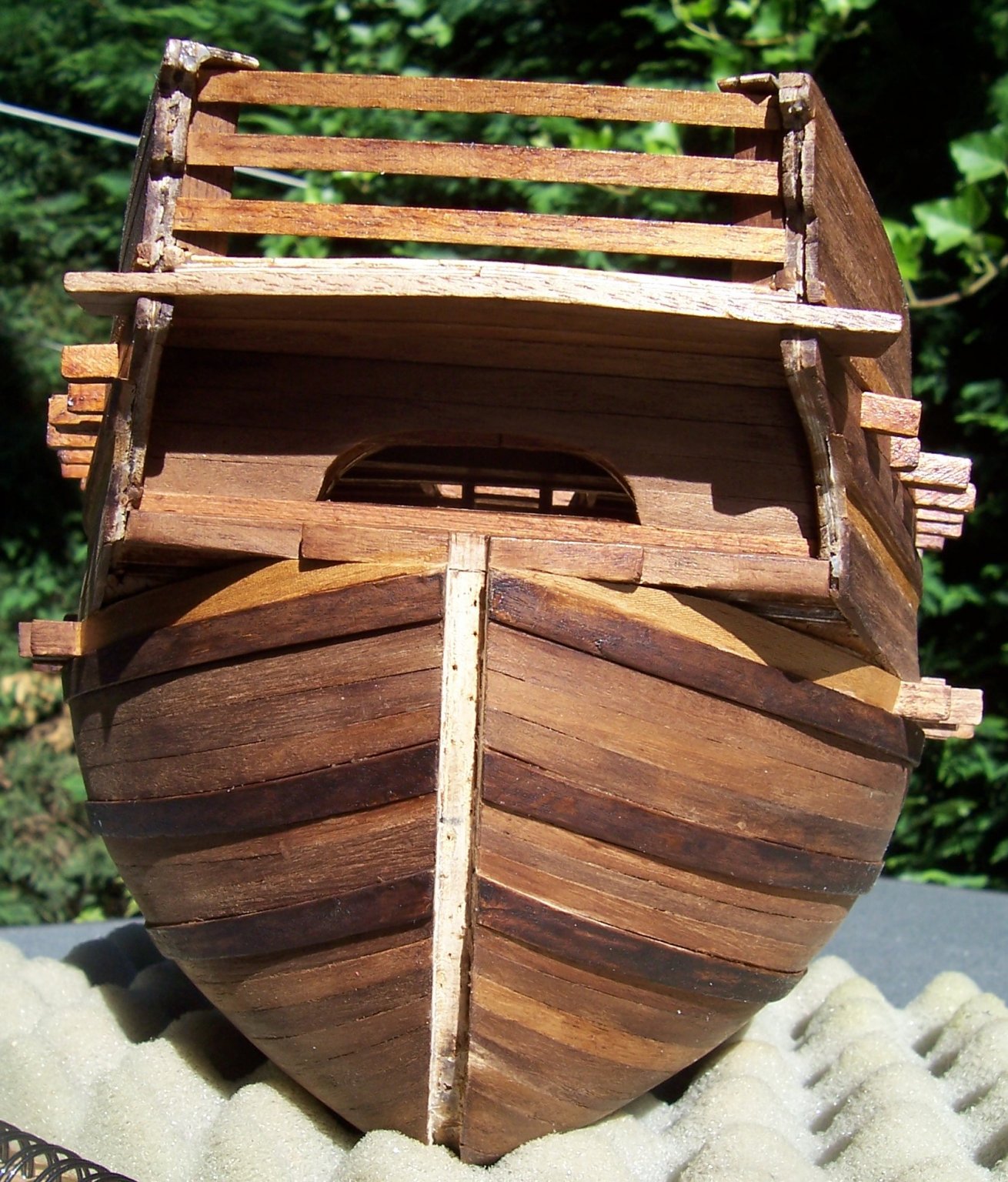
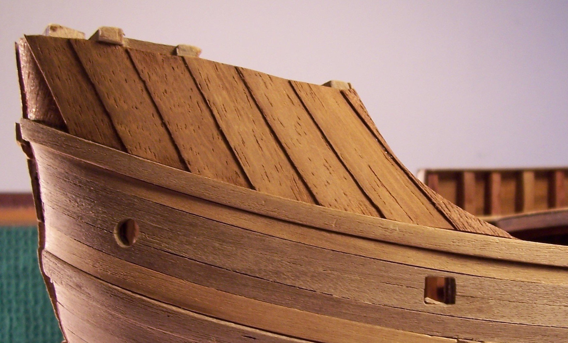
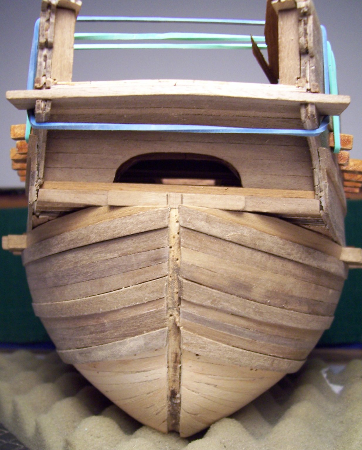
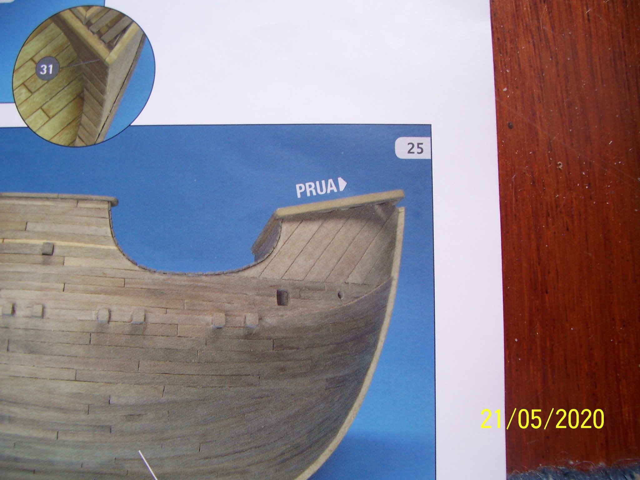
Now we have to work on grating at bow; instructions show a strange structure:
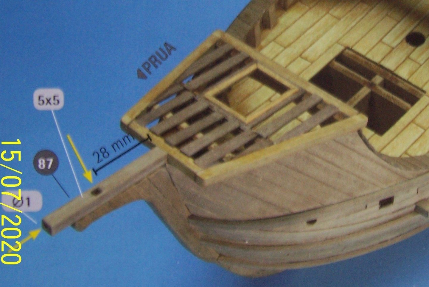
but contemporary images show a different kind of upper bow deck:
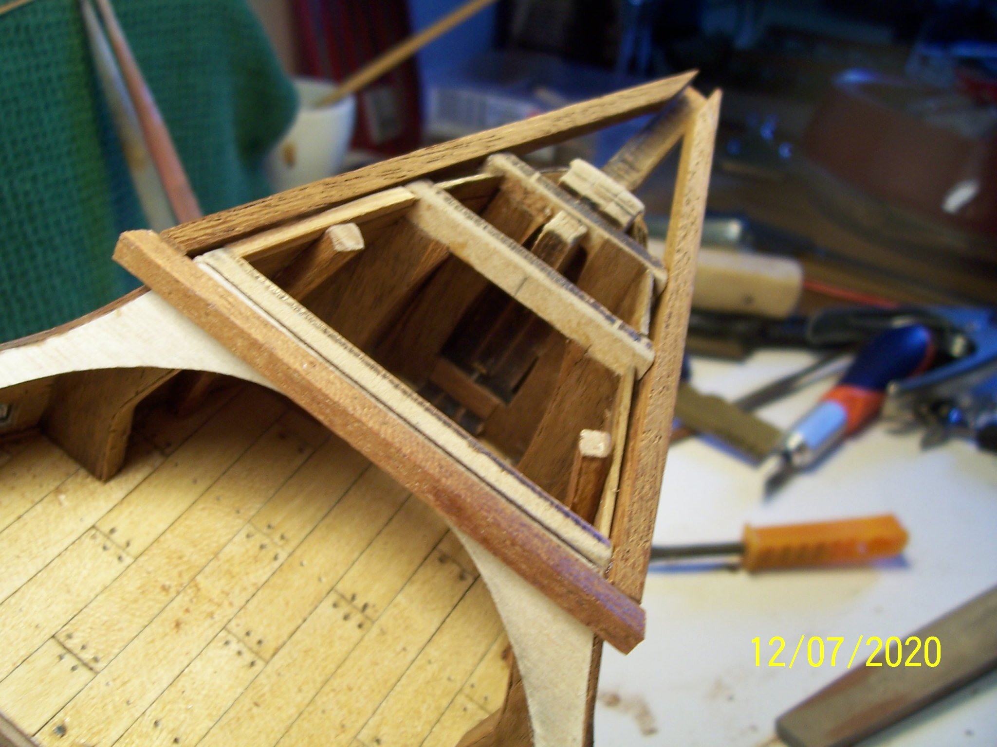
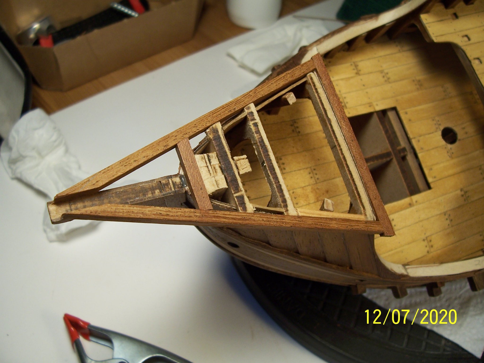
For for this reason I decided to build a triangular frame:

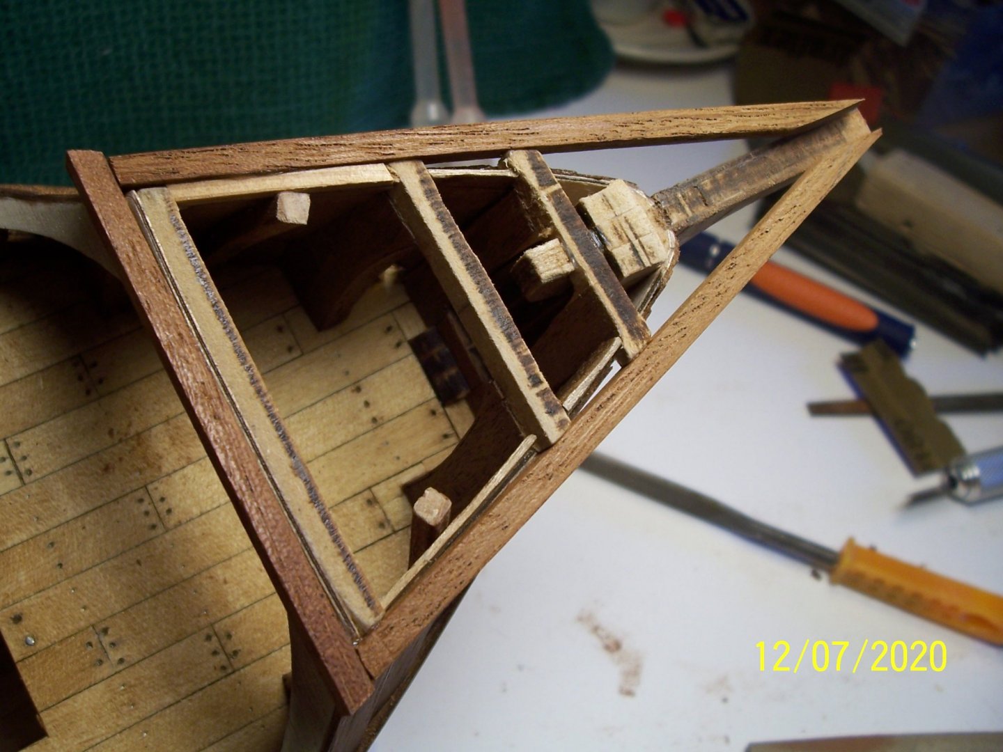

At this stage we've to add a crossbar:

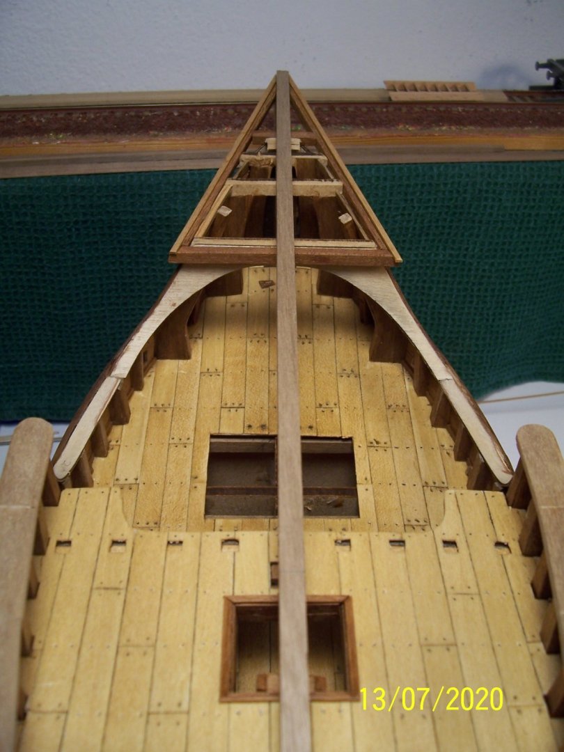
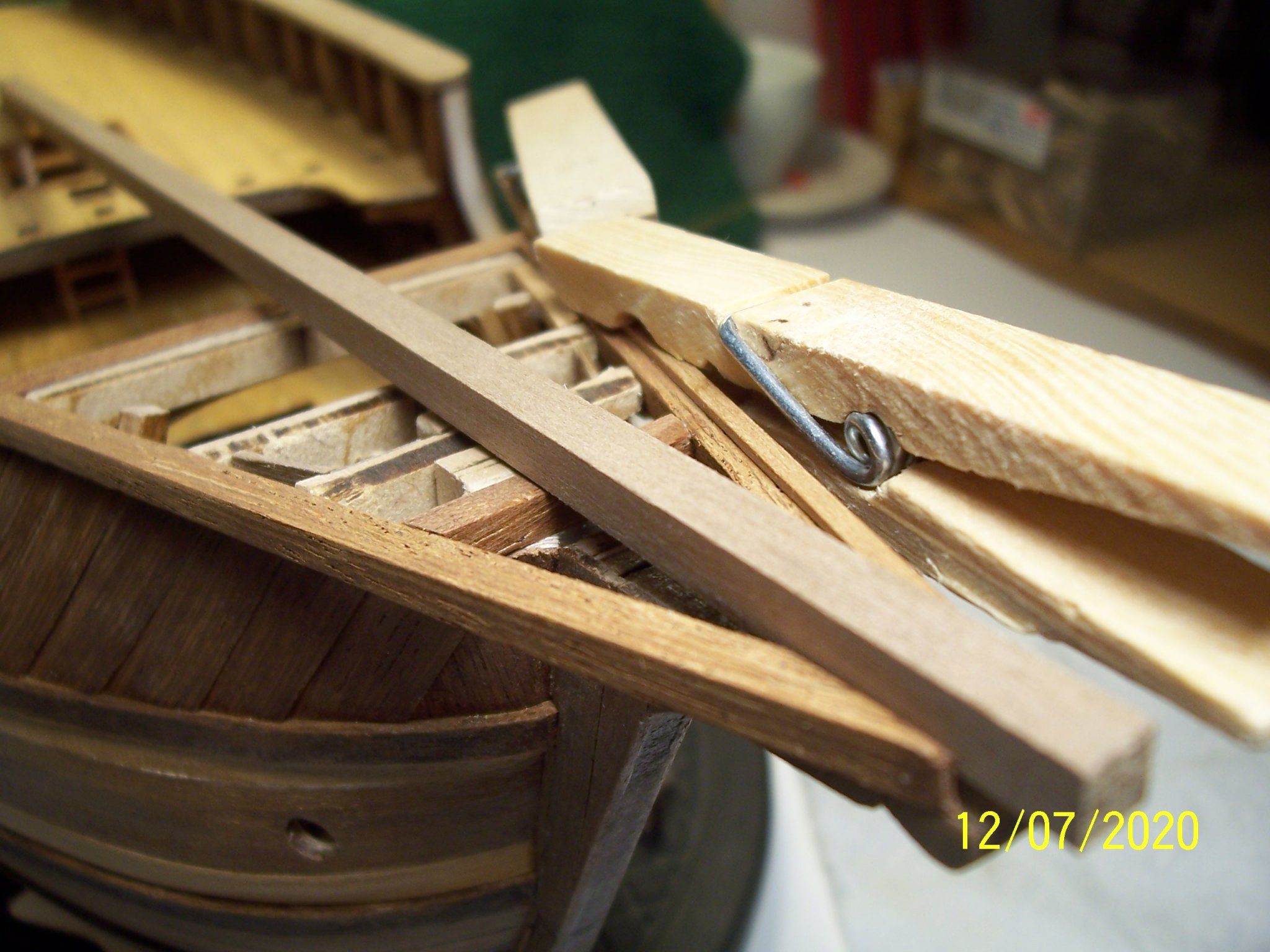
In order to avoid seeing the thin clear line of the deck planking strips, I glued a thin strip that will frame the entire structure:
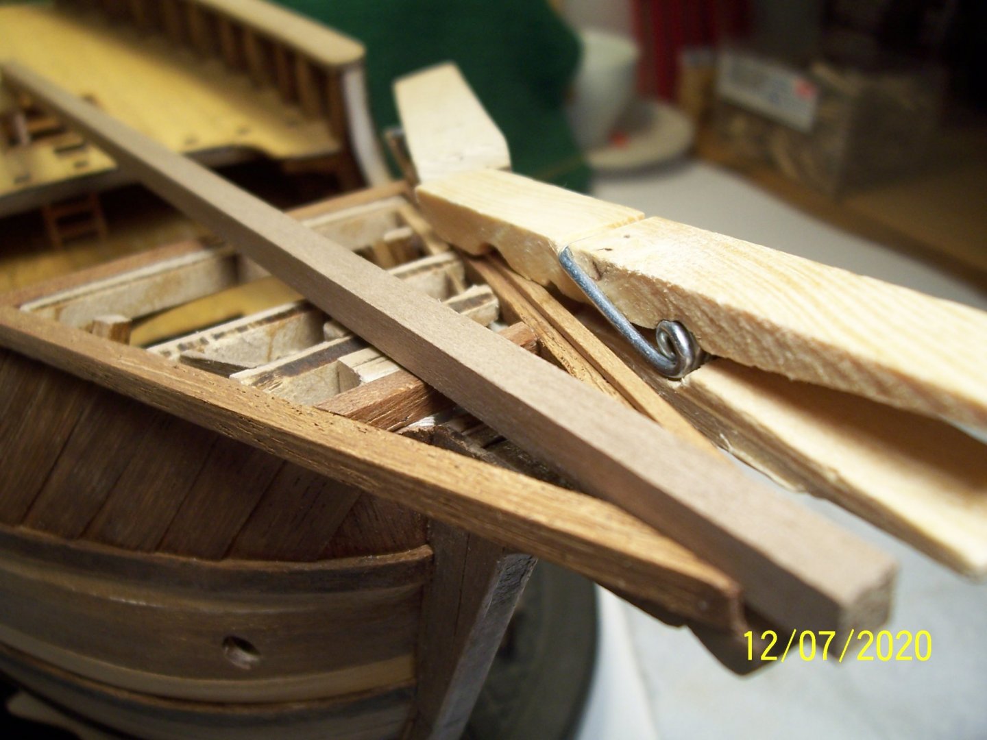

The long square strip has been used as a check for the accuracy of the work. After that we start with planking the deck:

See you soon!
Rodolfo
- J11, Baker, GrandpaPhil and 2 others
-
 5
5
-
Very nice work and interesting model! Perhaps a slight painting of the planking of the decks could be a further improvement...
Rodolfo
-
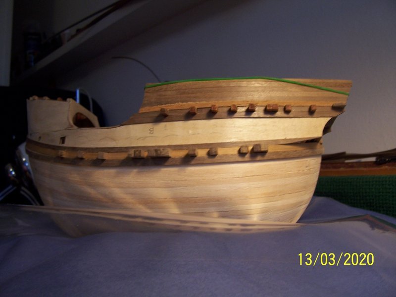
Dear all, thanks for the comments
 .
.
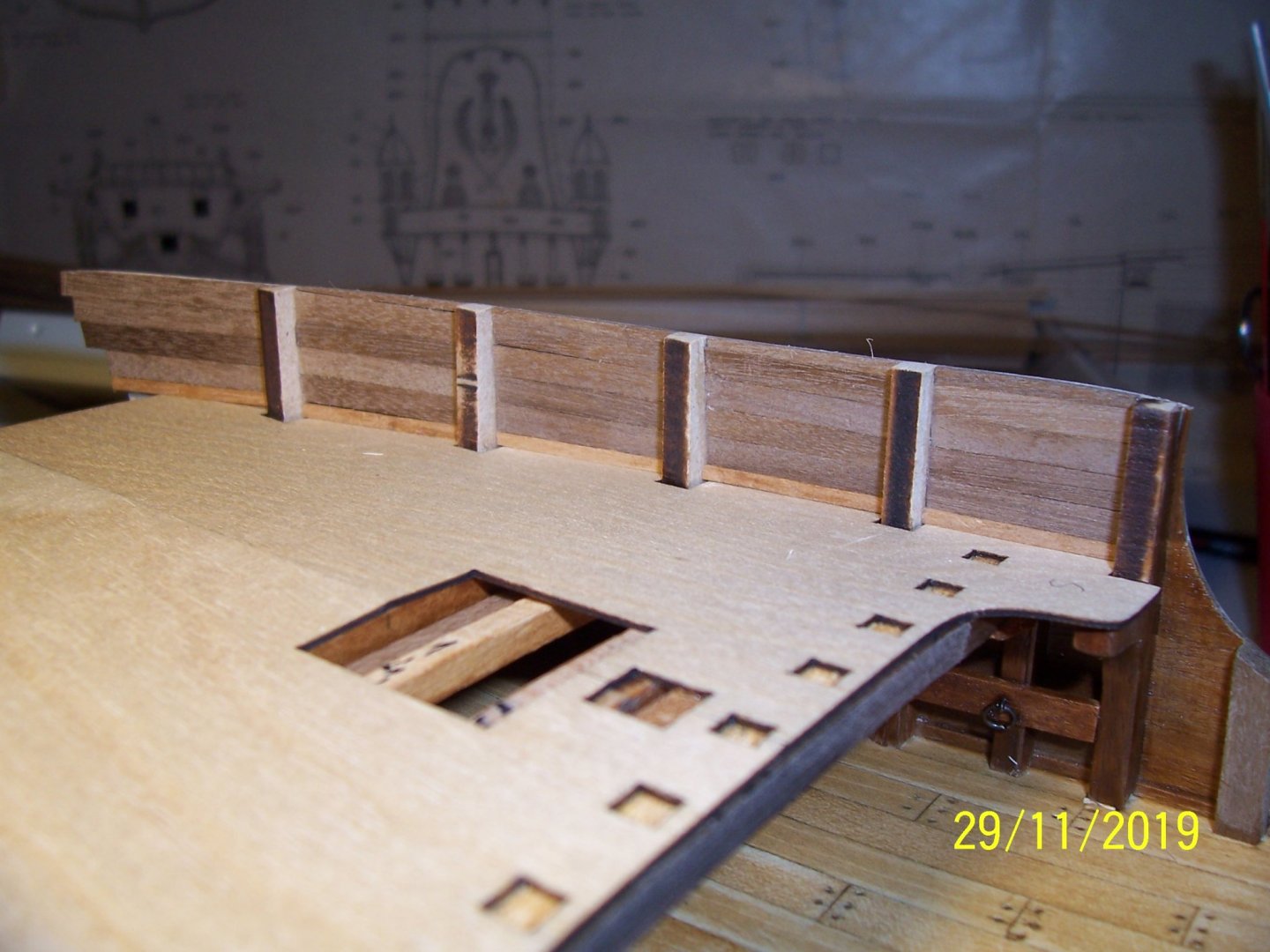
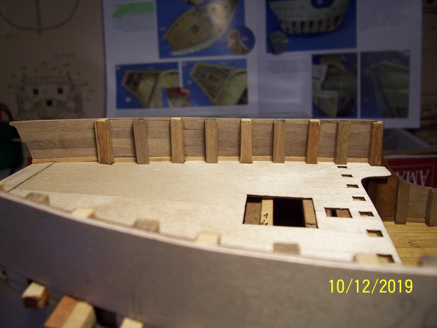
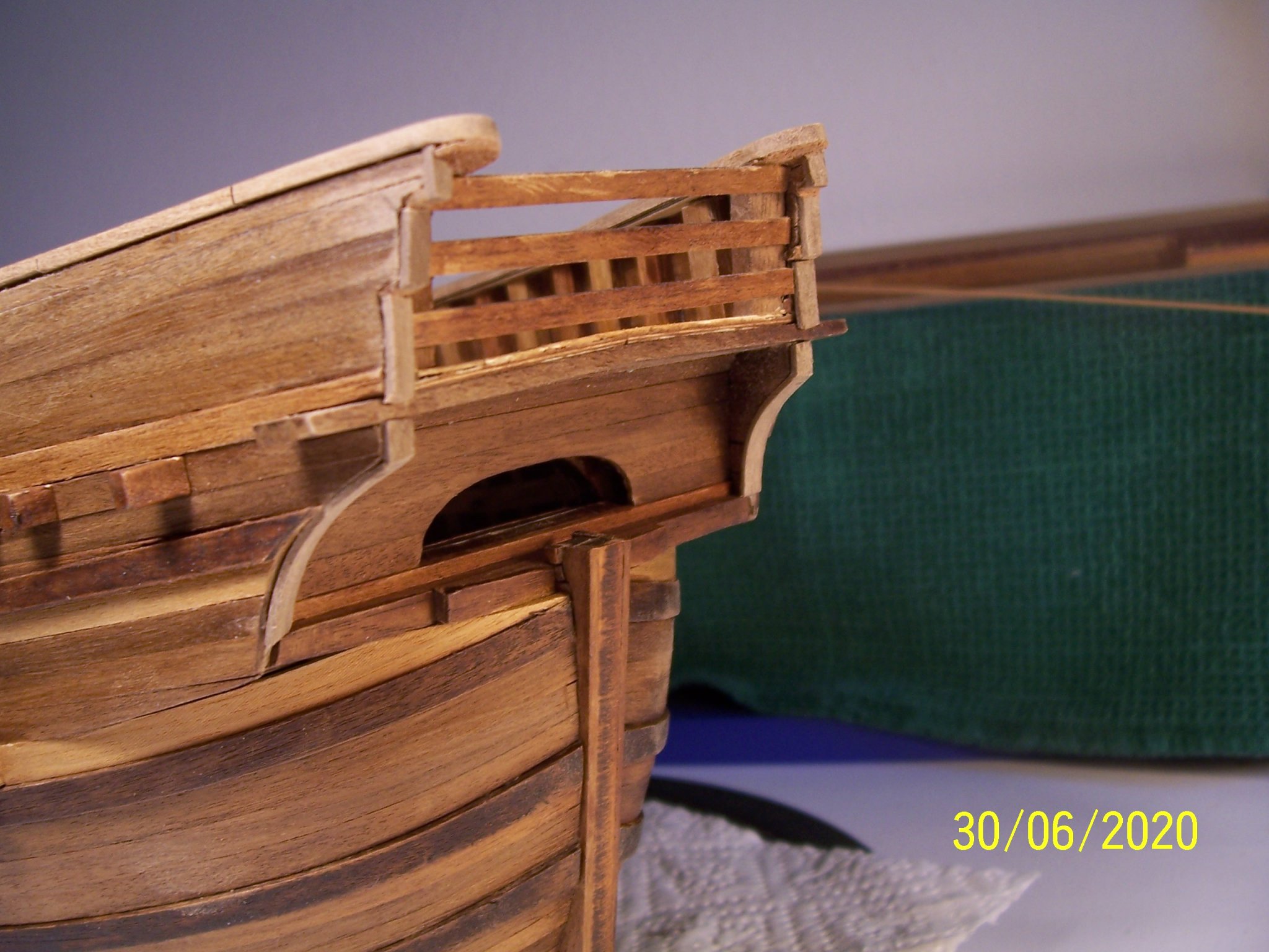
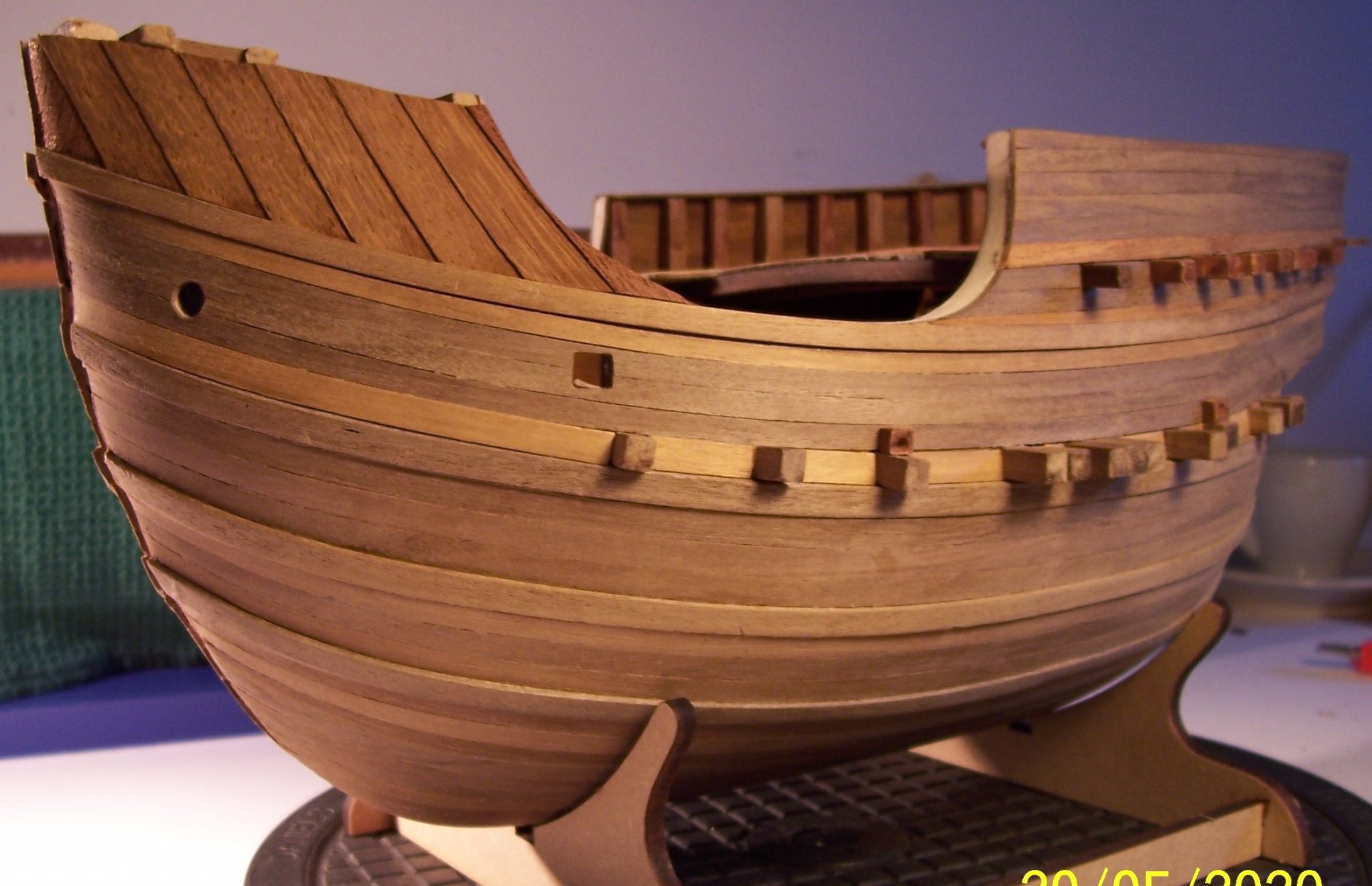
The work continued by planking top rails upper edges of quarterback bulwarks, using walnut strips (2x10 mm), cutting parts 30 mm length glued following the bending.
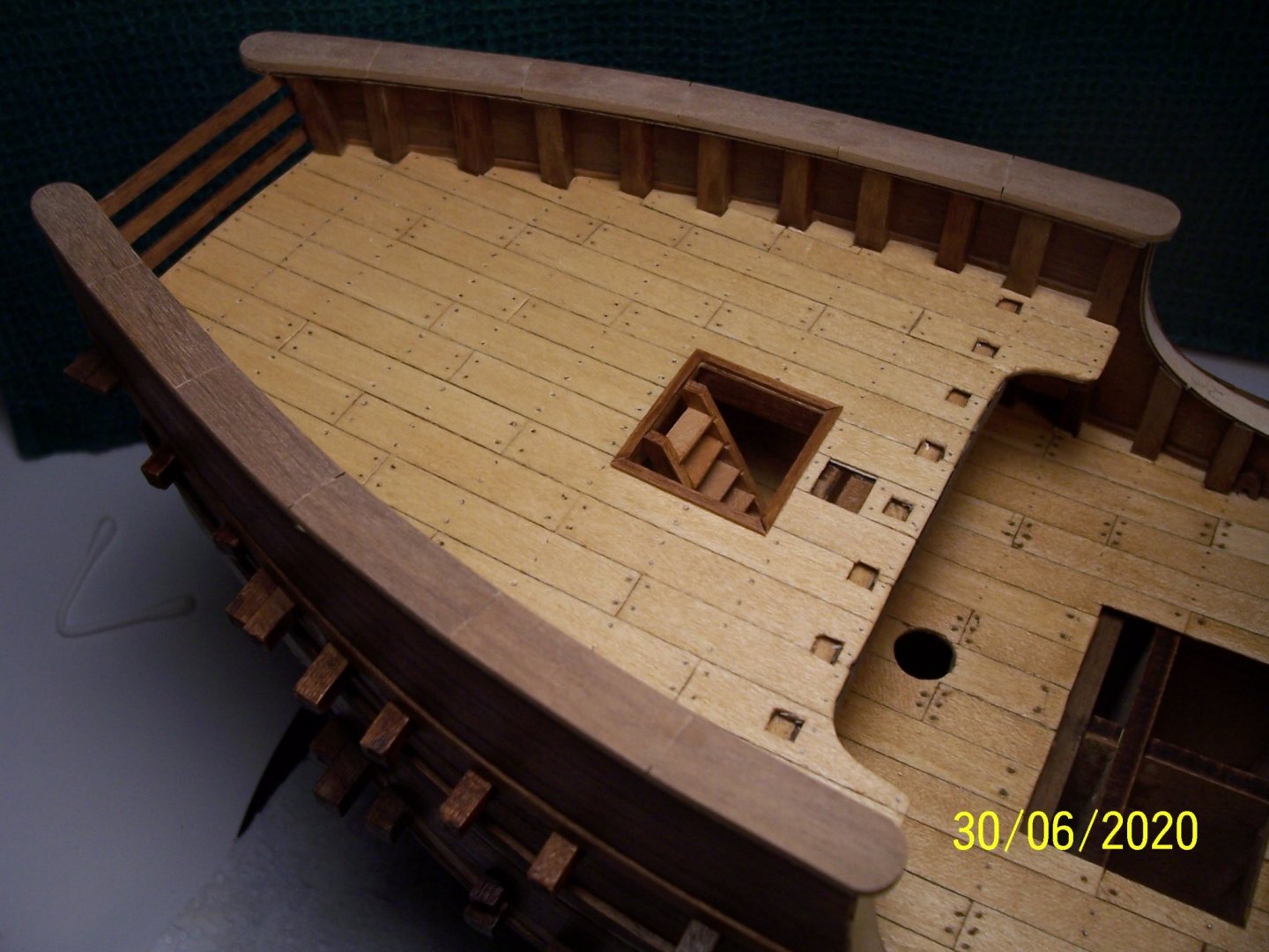
Moreover, the stern bulwark edges have been planked using wooden strips 1x3 mm:

Next step will be the grating at bow.
See you soon!
Rodolfo
- KentM, Louie da fly, Baker and 2 others
-
5
-
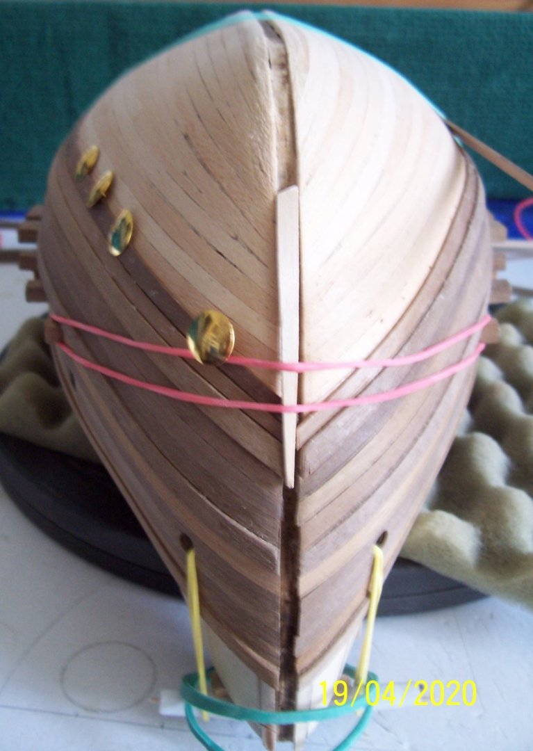
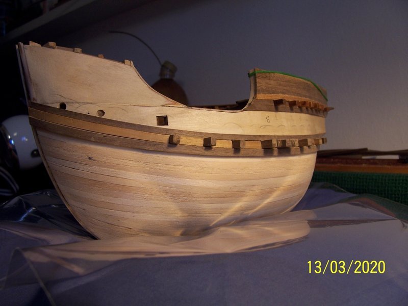
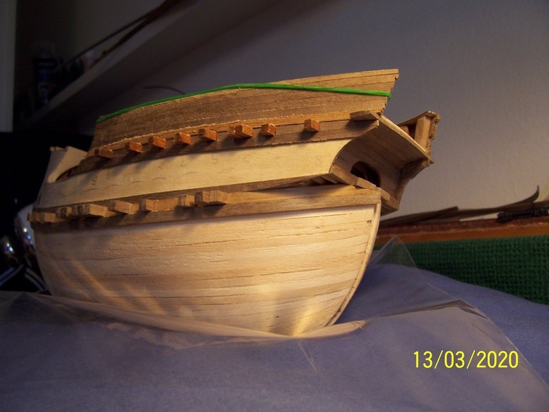
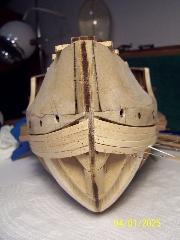
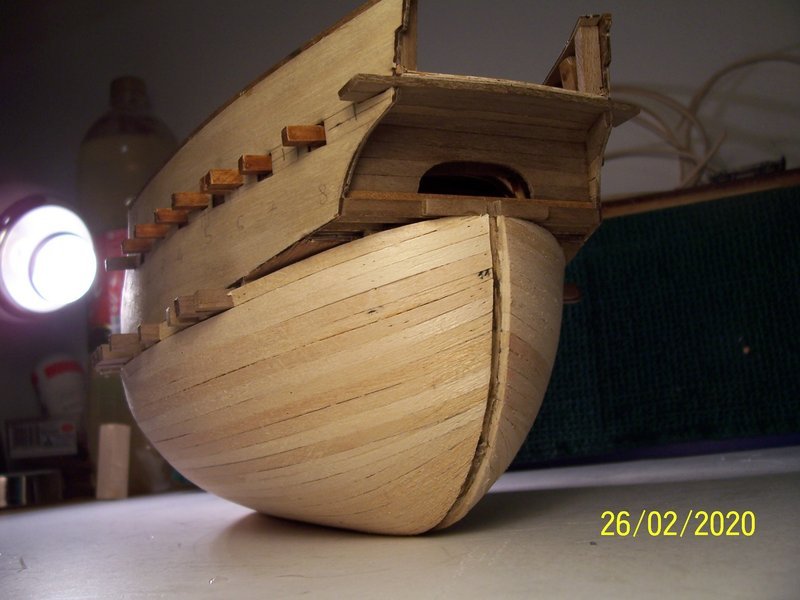
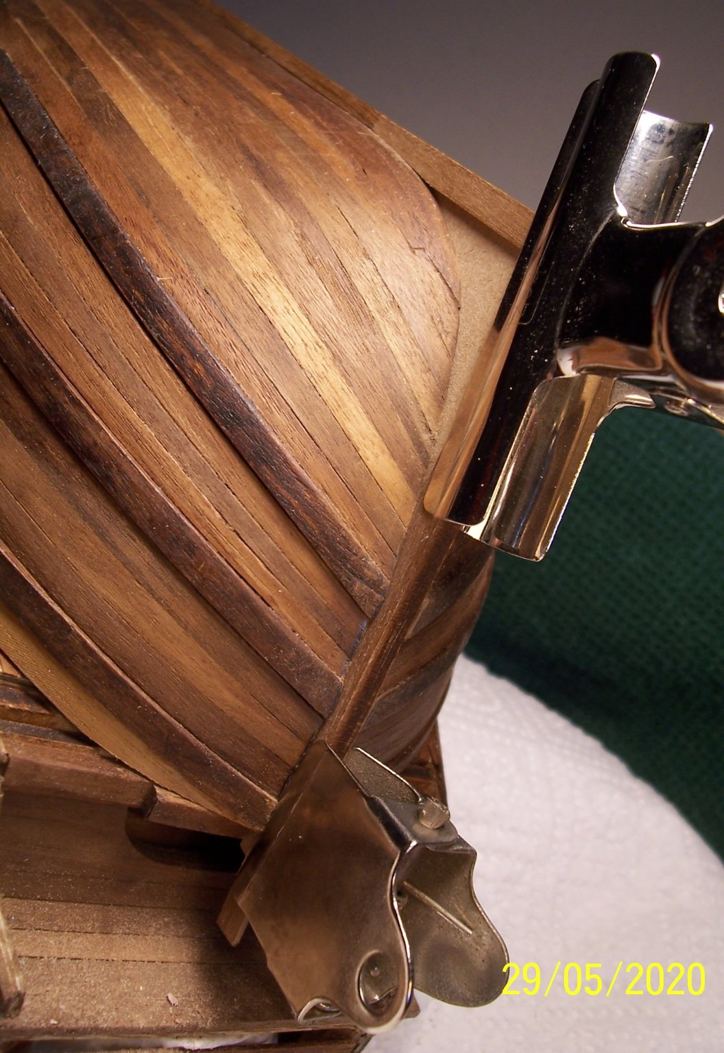
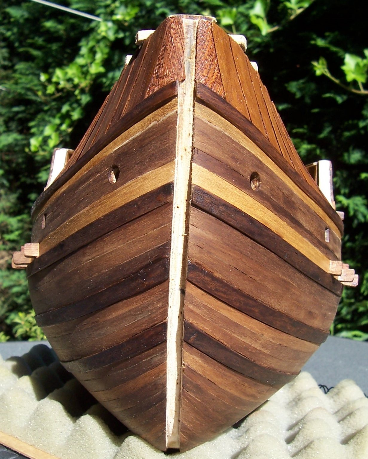
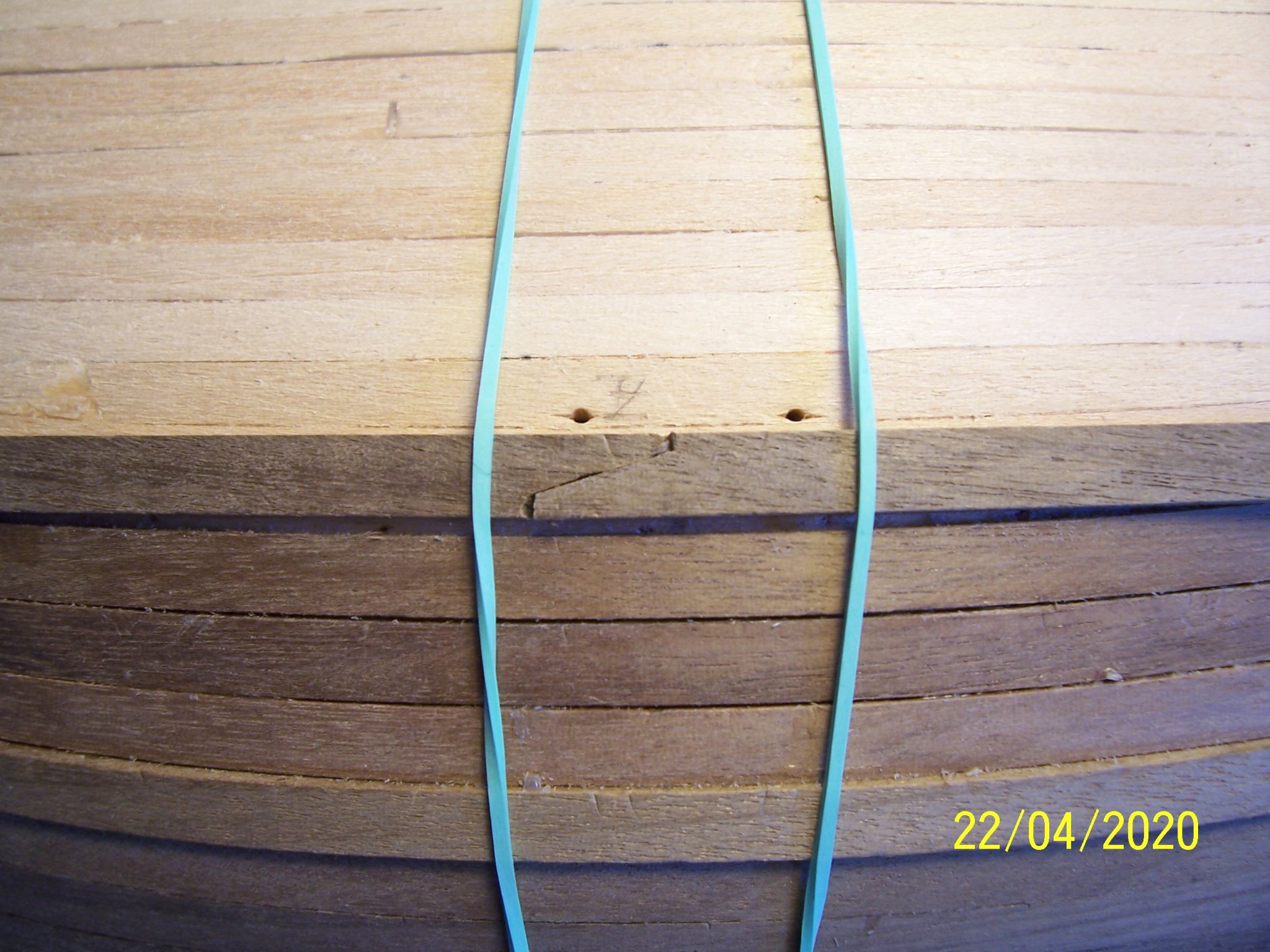
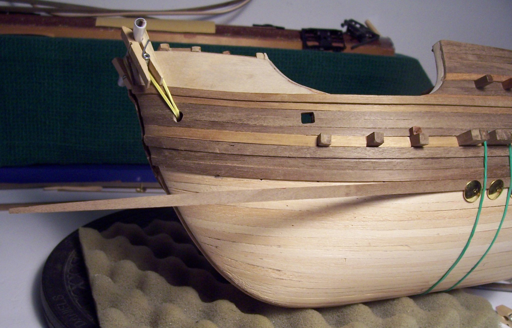
... here we are again.
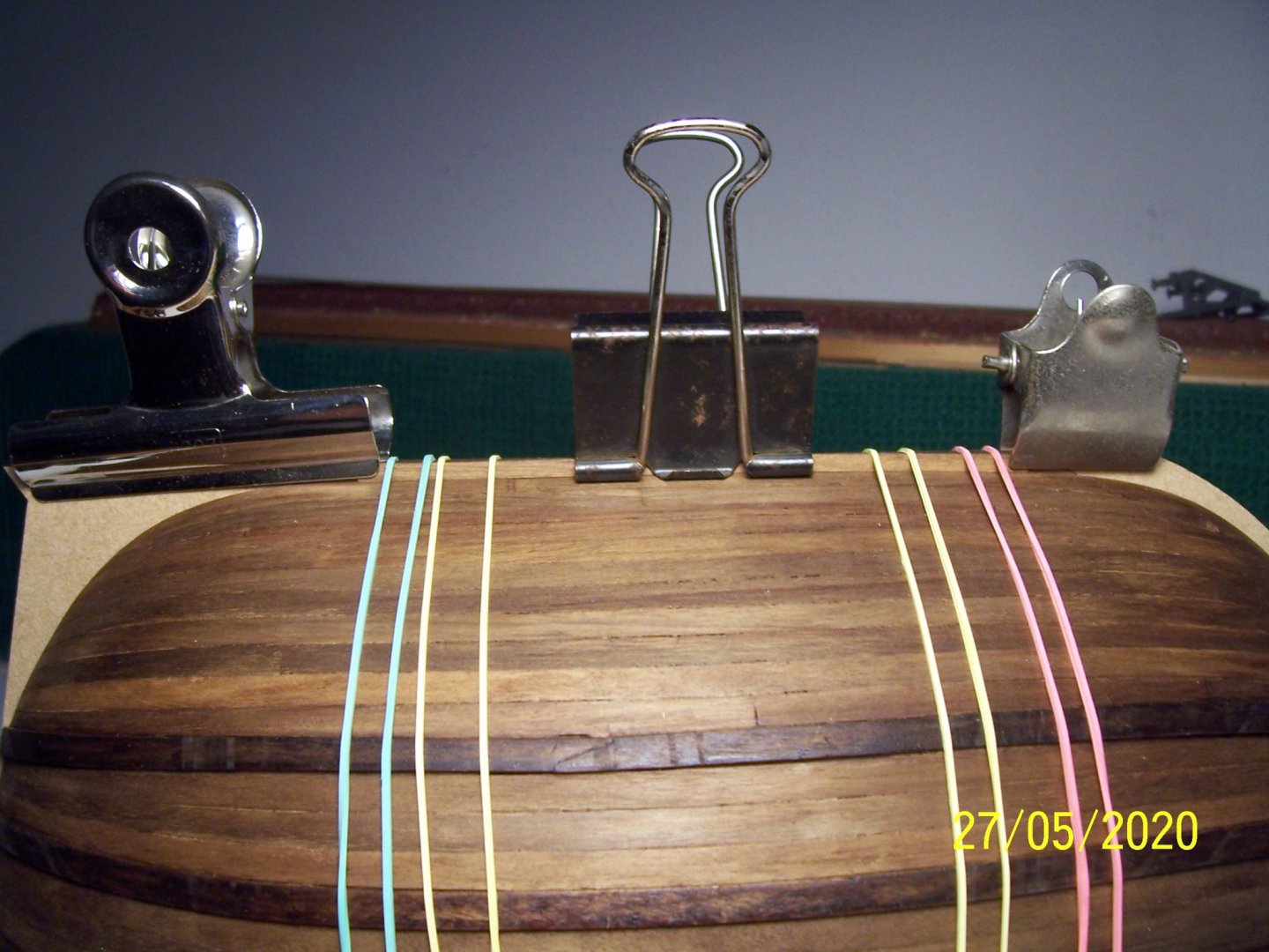
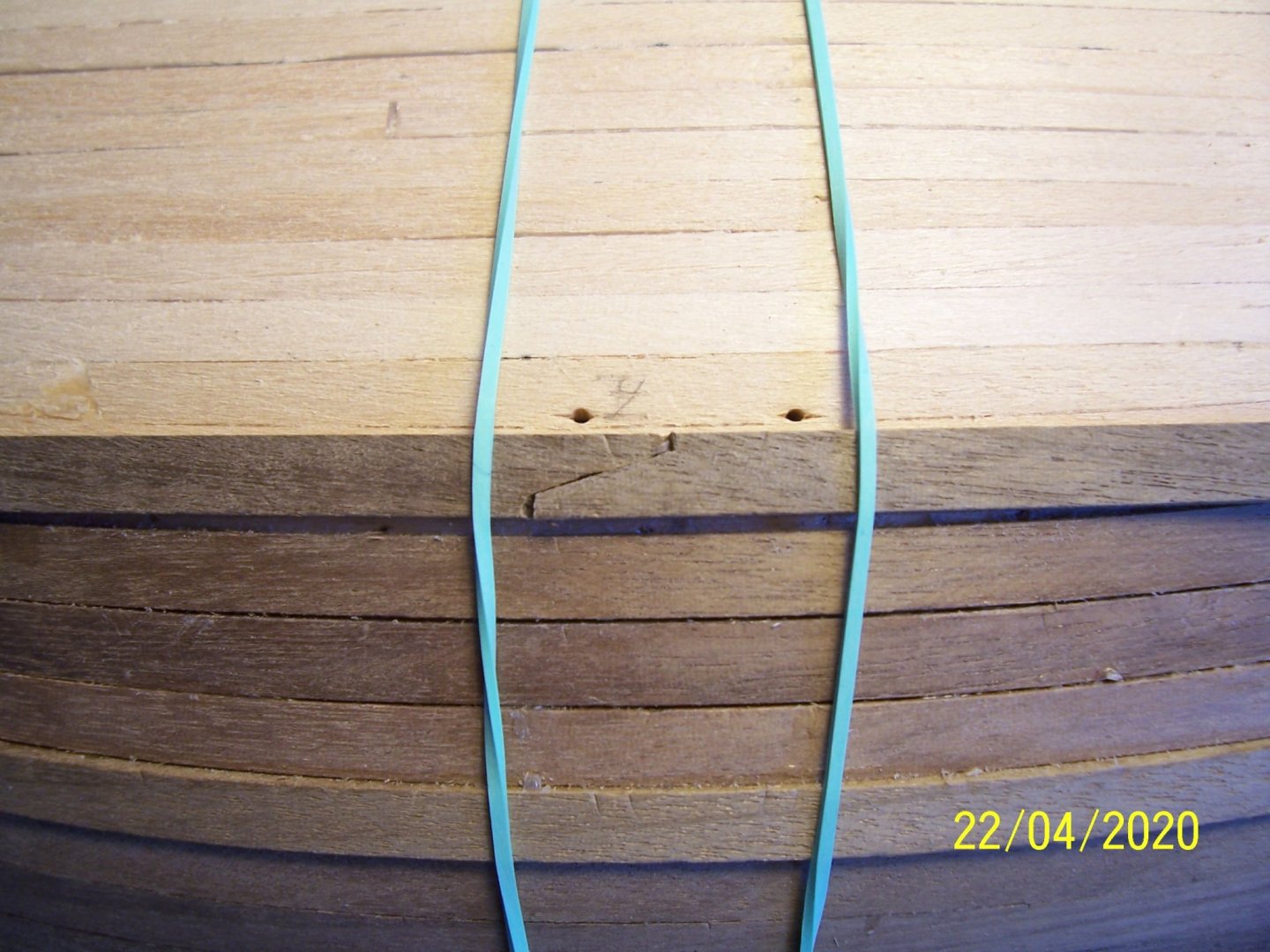
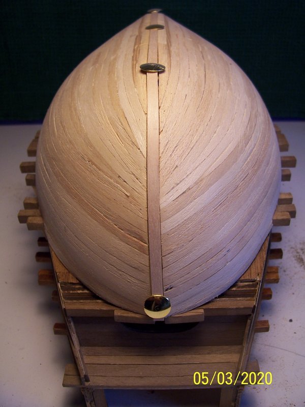
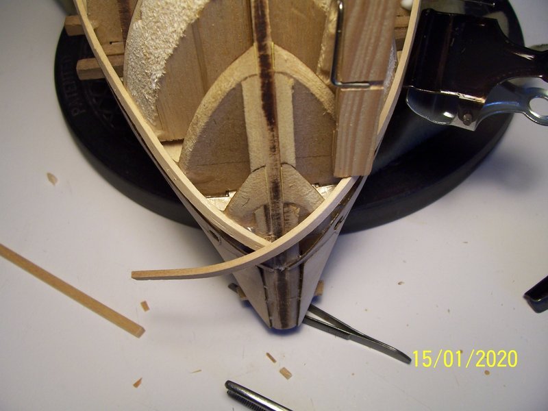
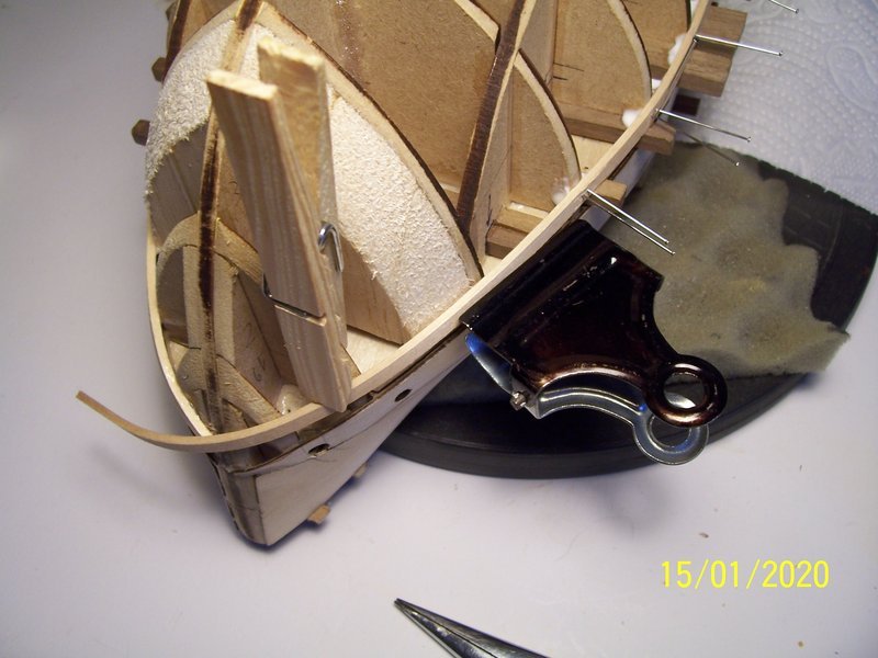
Before starting to cover the keel near bow, I noticed that the spur was not perfectly straight and therefore I added a little glue keeping it in tension:
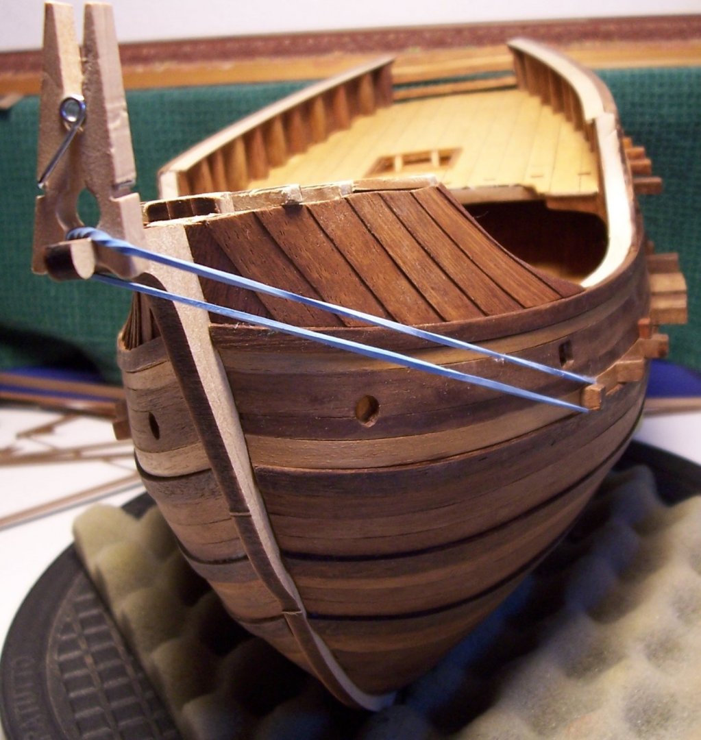
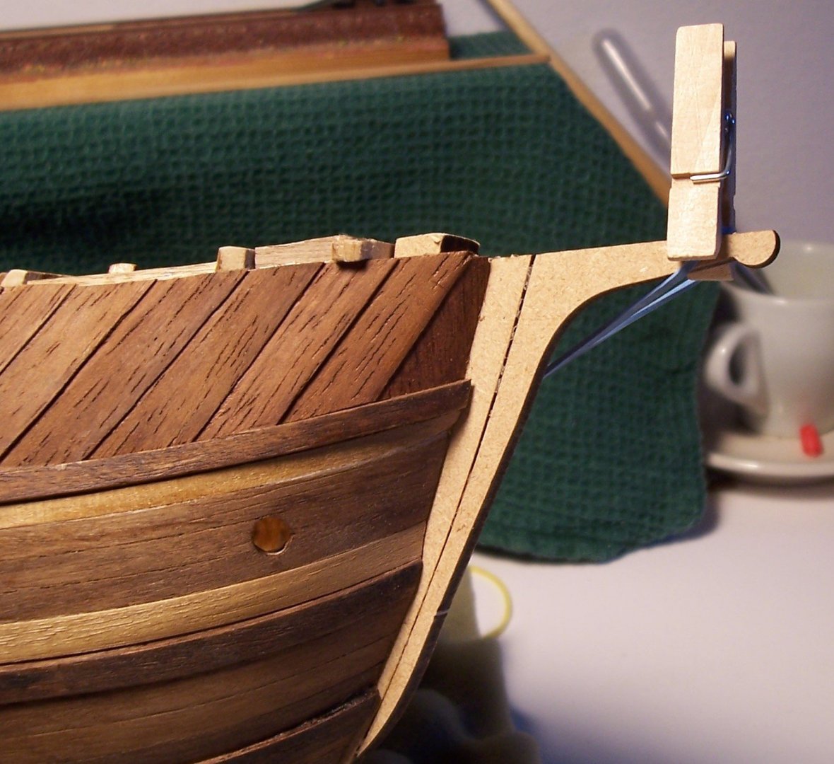
By the way, the ship is still perfectly balanced:

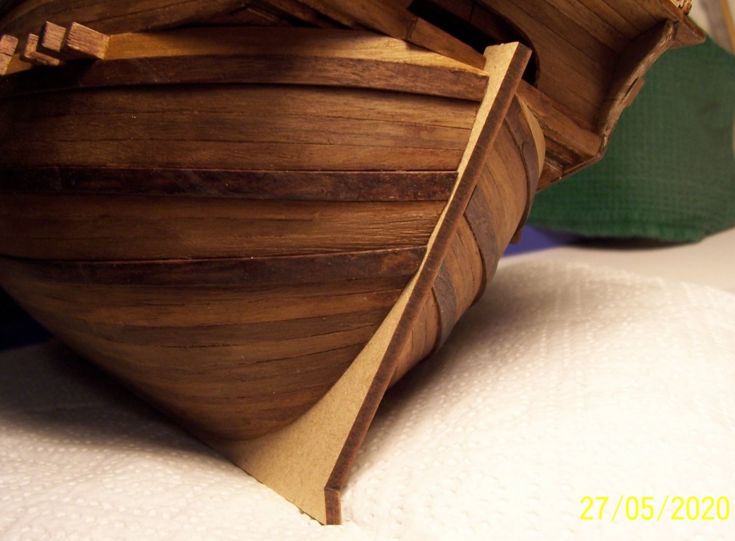
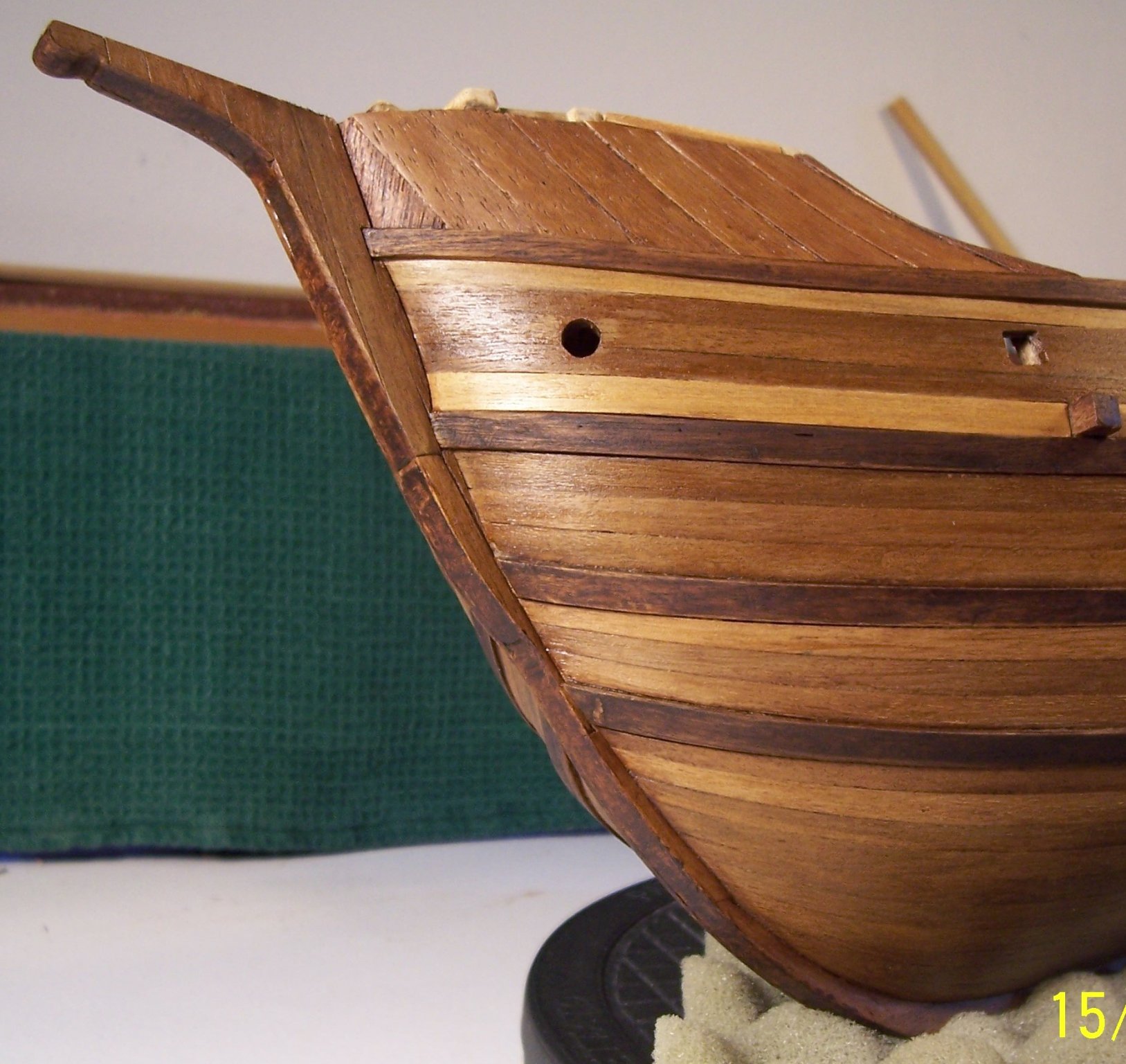
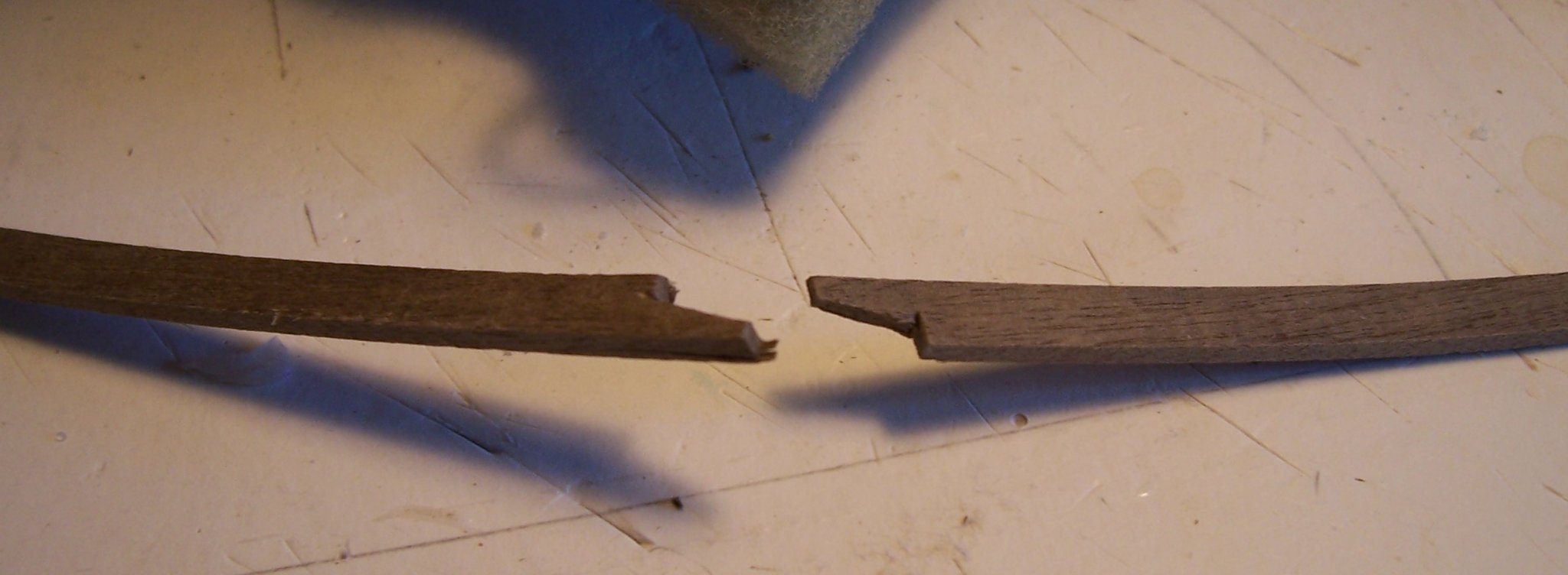
For covering the remaining keel, I made 1 mm grooves in certain places and in others I have shaped the pieces of strip in a curvilinear way:

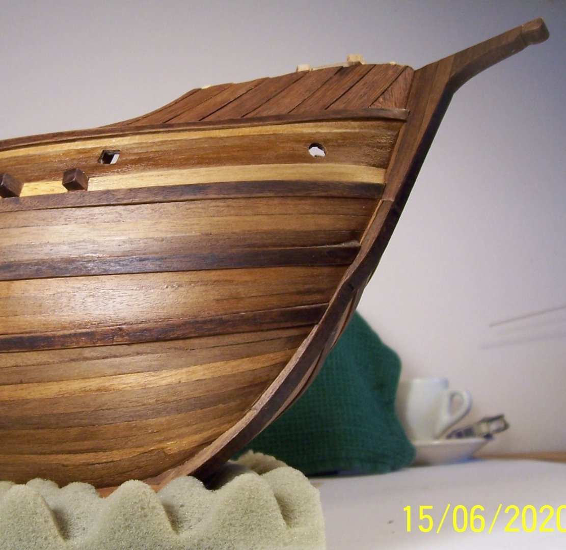

And so we arrived at the current situation.
Now I go back to work, see you soon!
Rodolfo
- tarbrush, Halfdan, BLACK VIKING and 5 others
-
8
-
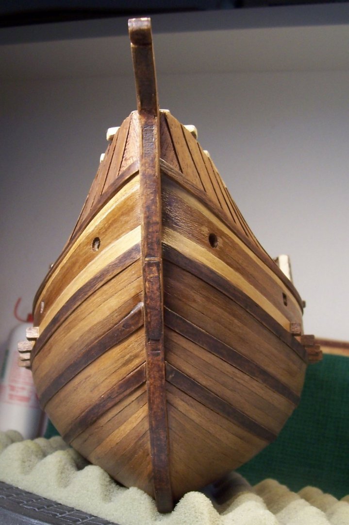
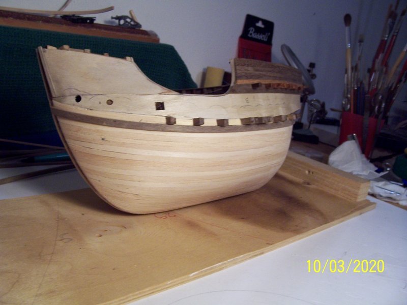
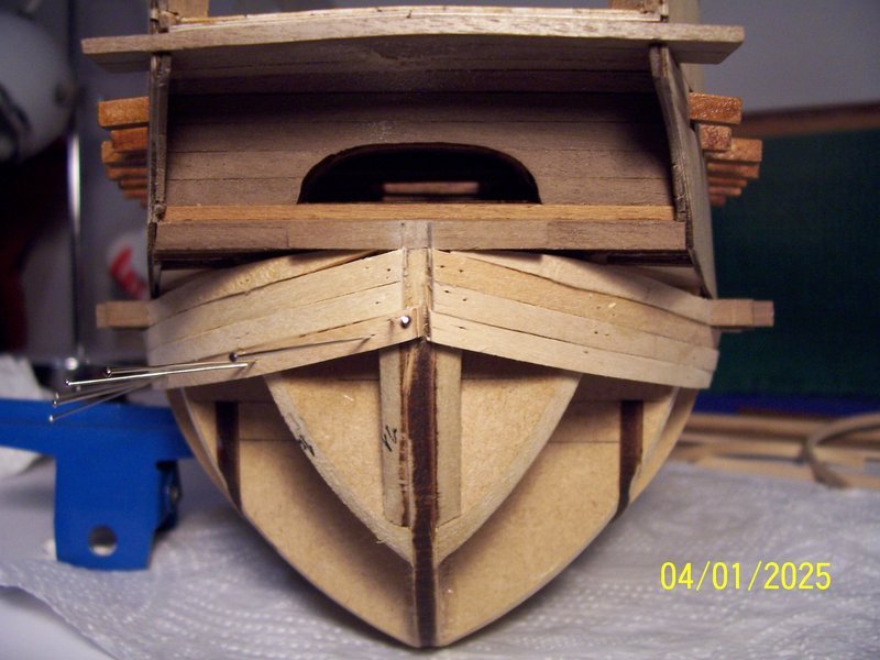
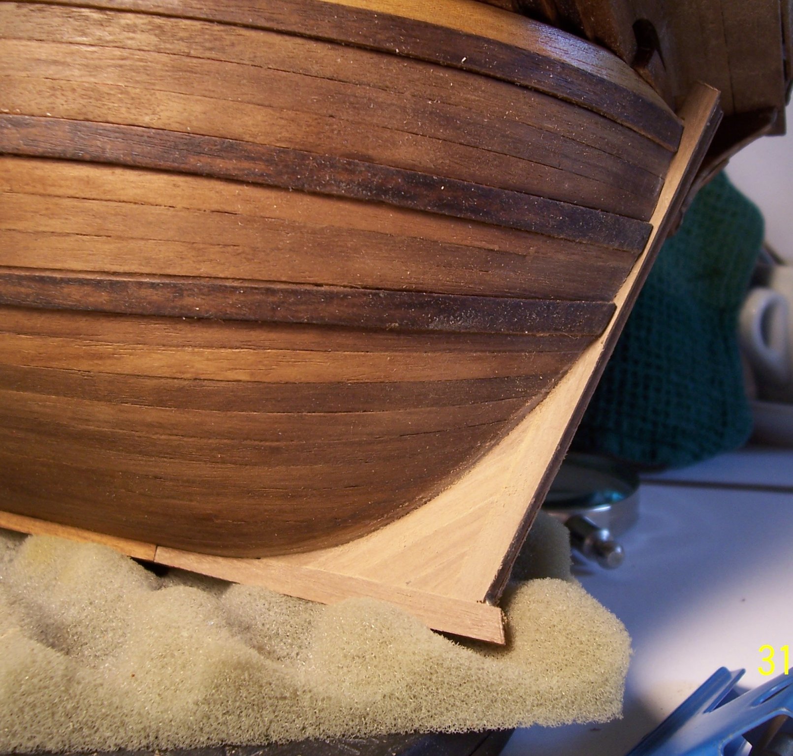
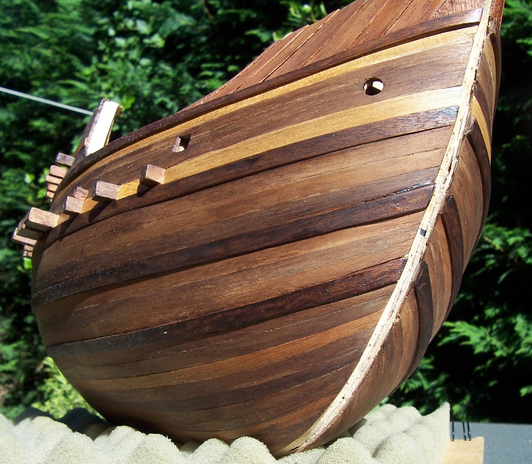
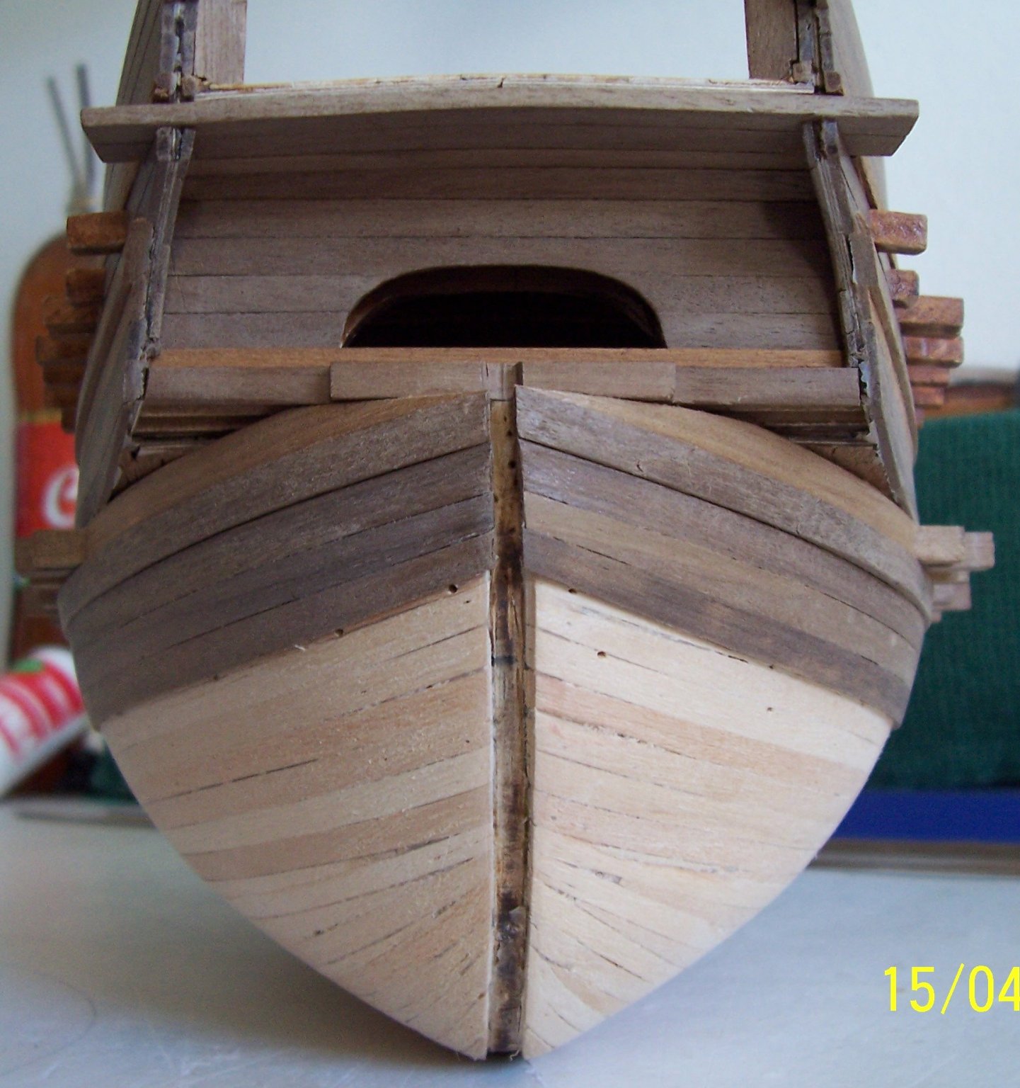
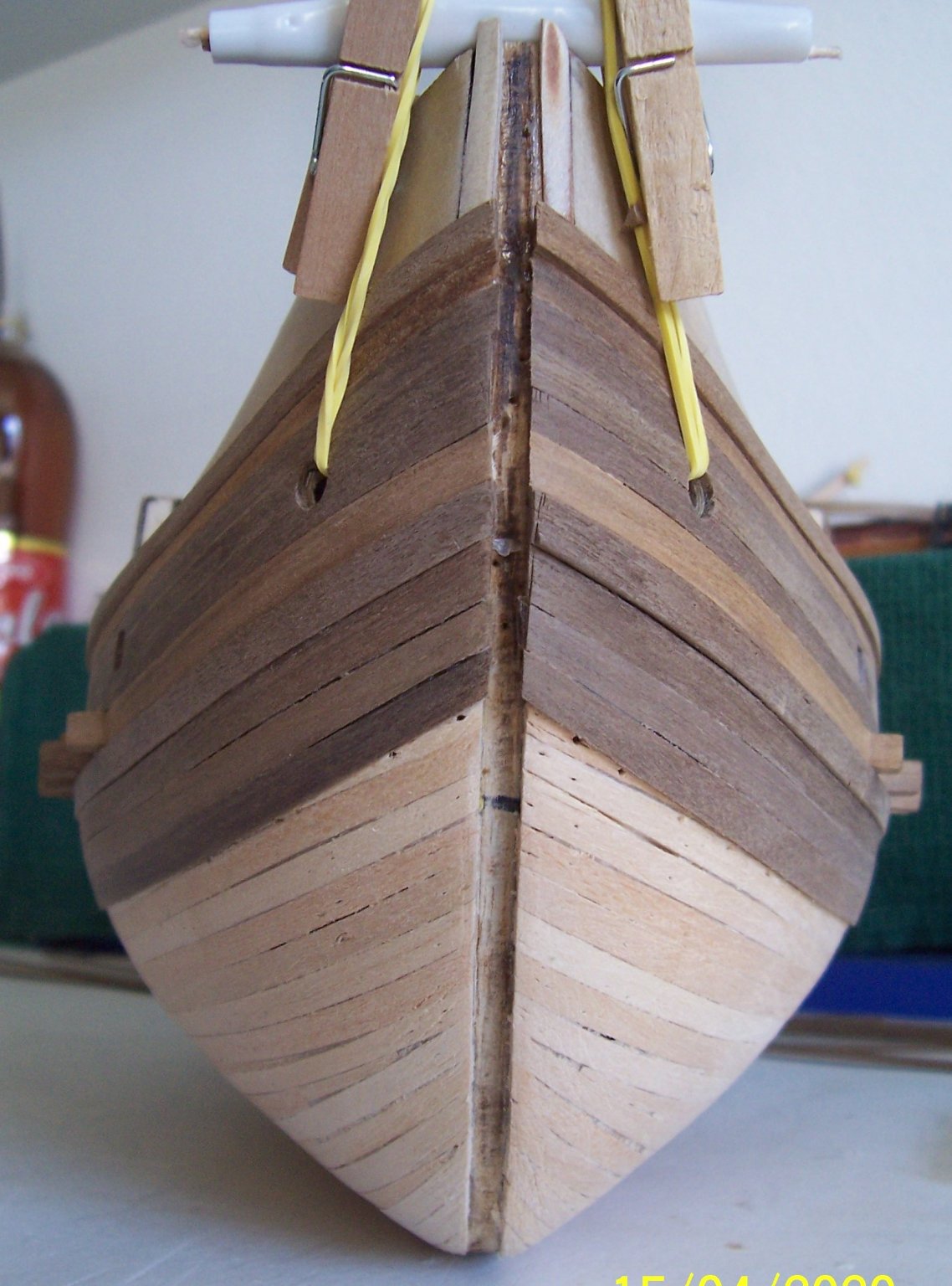
Welcome everyone!
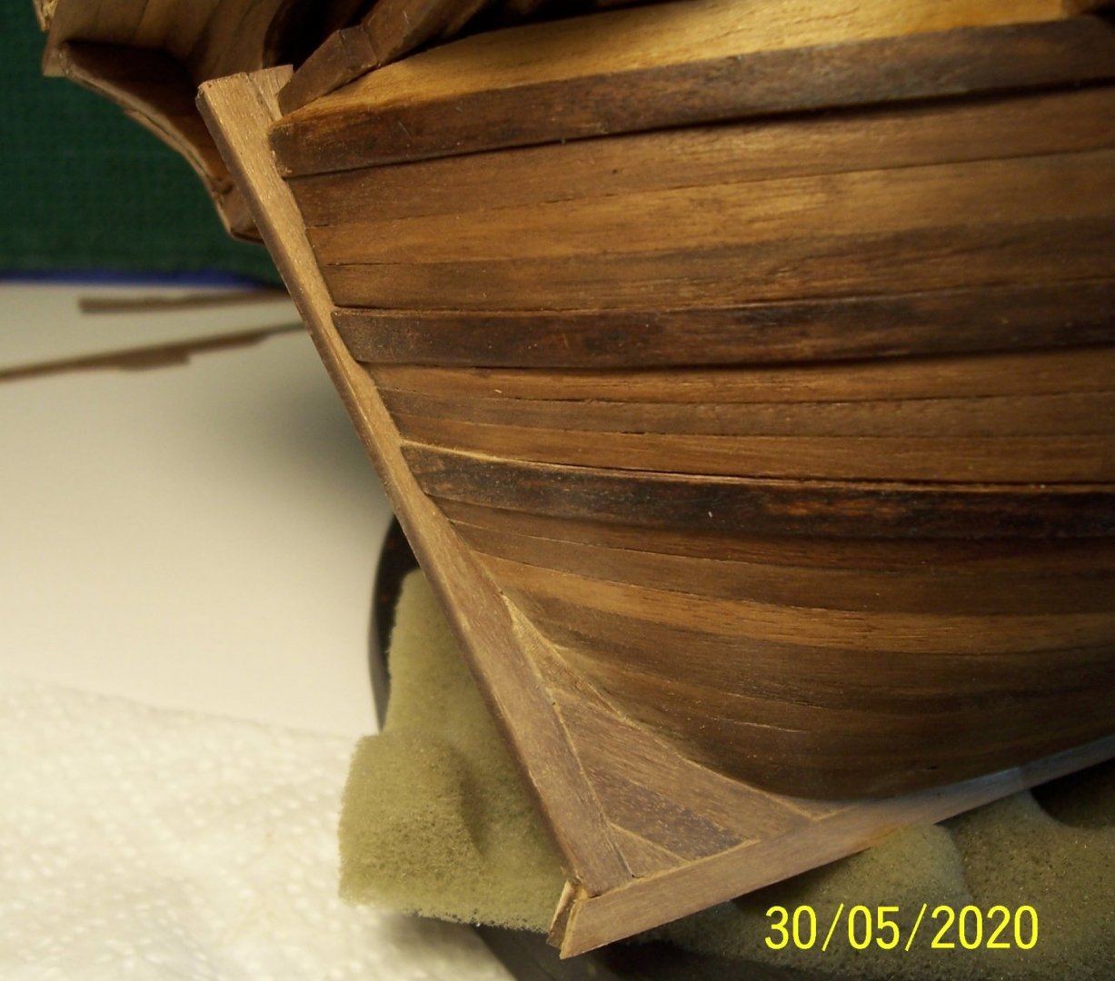
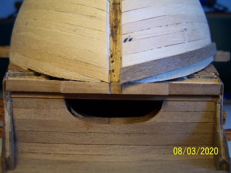
First step is checking raw keel in the groove between the two sides of the planking:

After that, we start to glue straight strips of walnut on the bottom:
Now it's time to go to complete the keel toward stern:

In order to avoid the difficulty of shaping the strips perfectly, I made a 1mm groove to insert the strip under the planking.
After that, the coverage of the free spaces with pieces of strip remains to be completed:

to be continued...
Rodolfo
- Baker, Moab, GrandpaPhil and 3 others
-
6
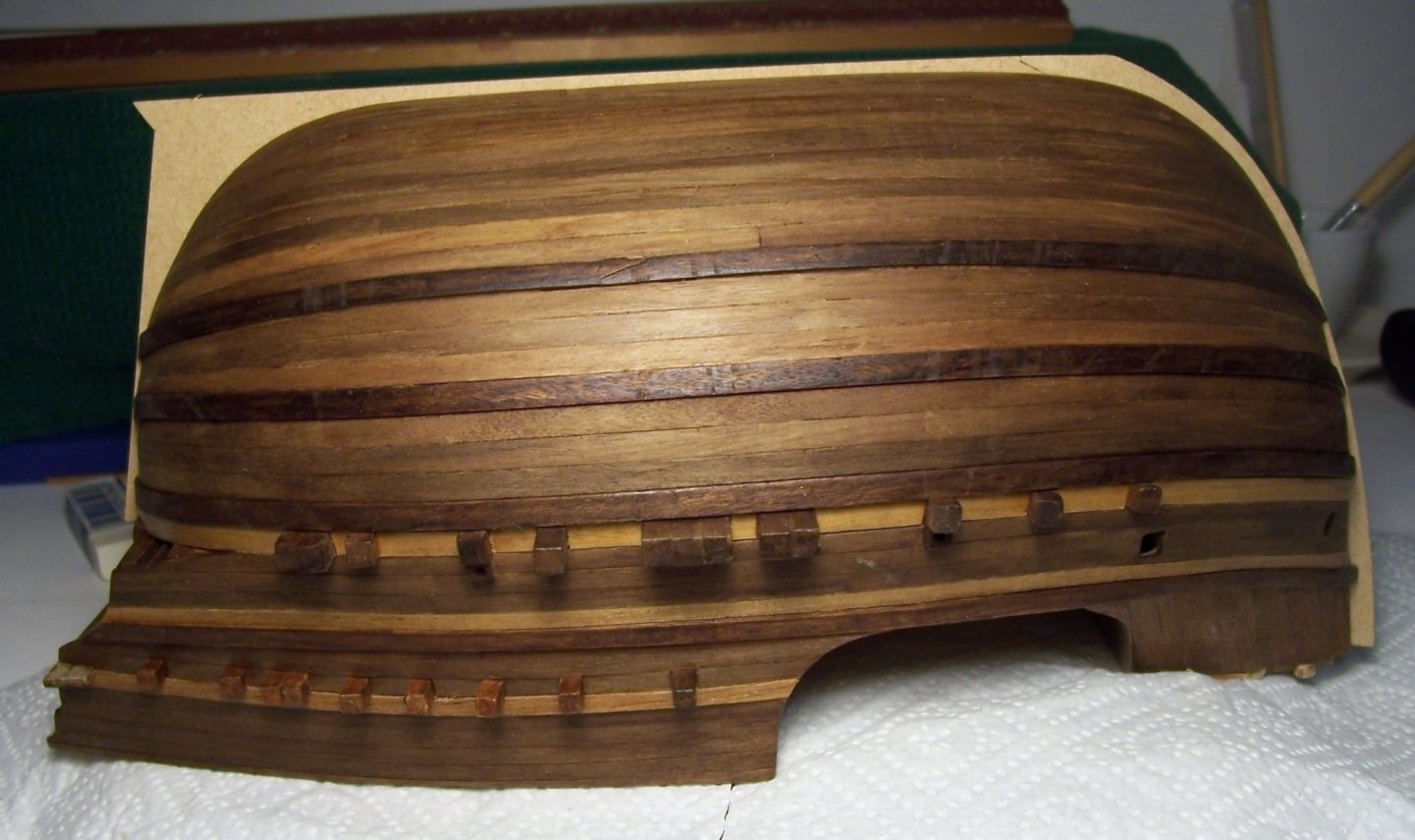
-
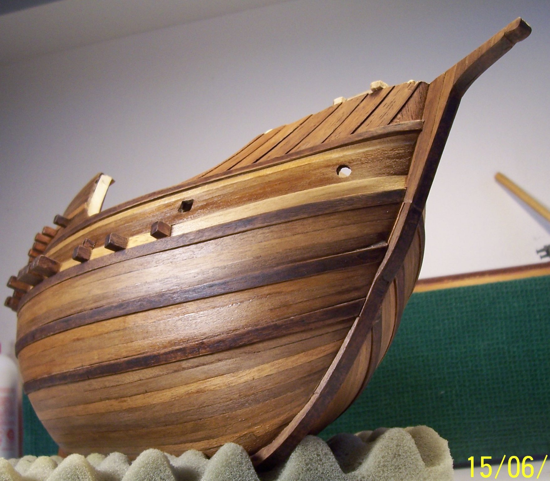
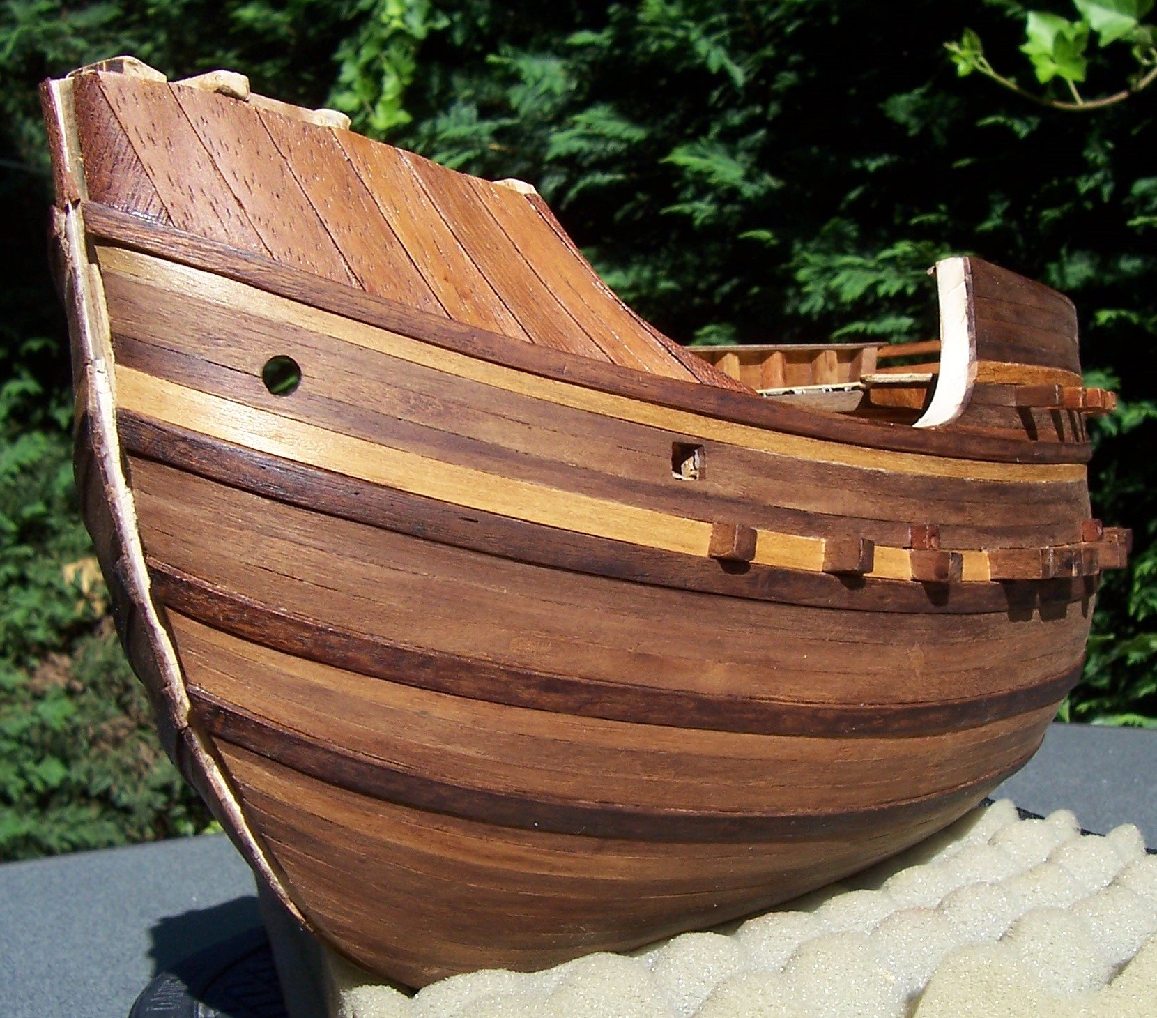
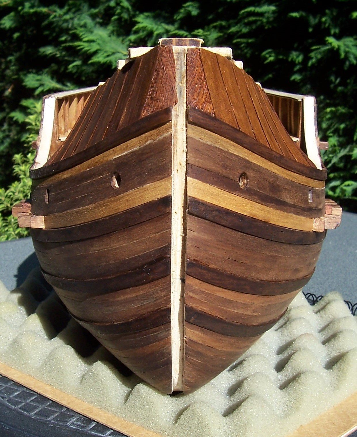
And finally this is the result of the use of impregnating varnishes for wood with dark walnut tones:


And now we can go to work on the keel.
To the next update!
Rodolfo
- Louie da fly, KentM, Baker and 2 others
-
5
-
Thanks Steven for watching my post.
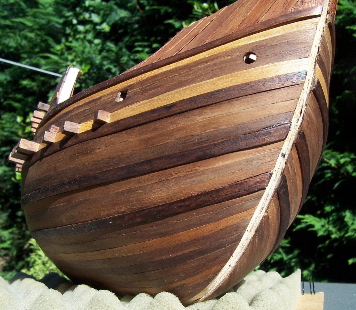
Actually, instructions suggest to use a strips having lengths 85 mm, but I was afraid that would not be possible to obtain an orderly sequence of joints, falling on the perimeter of the frames (and the pictures showing the completed ship will confirm that).
For this reason I preferred to use whole strips (tapered) from bow to stern.
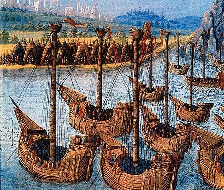
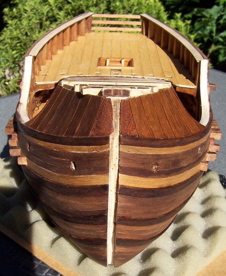
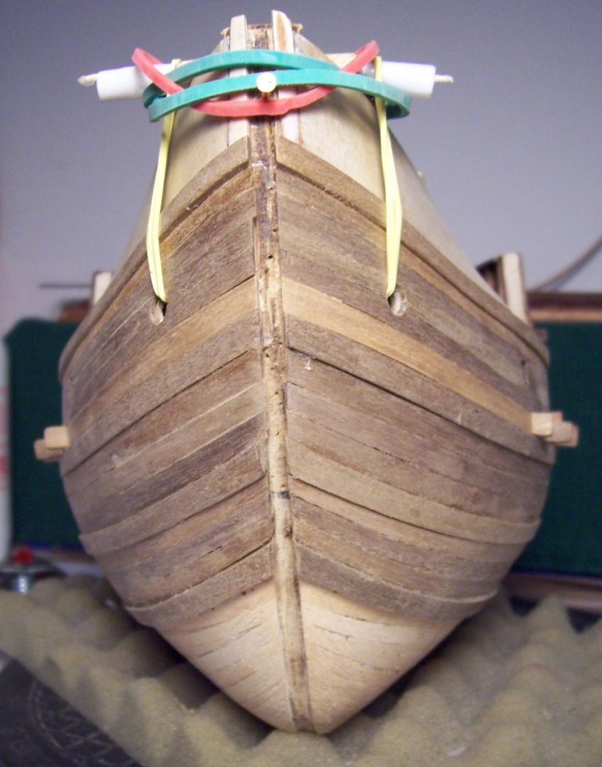
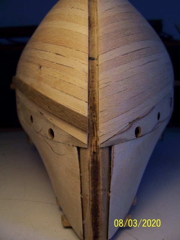
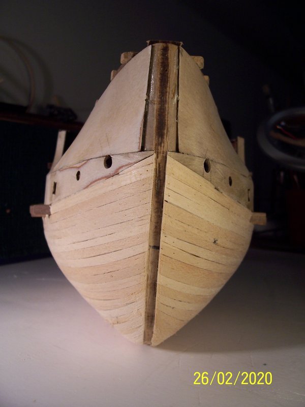
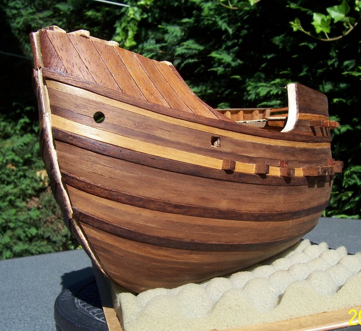
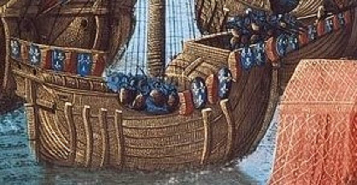
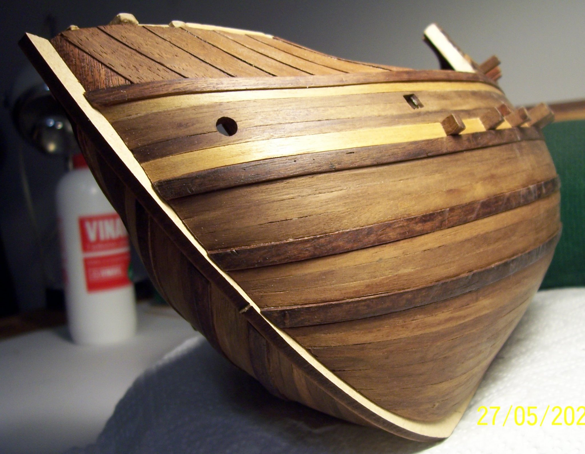
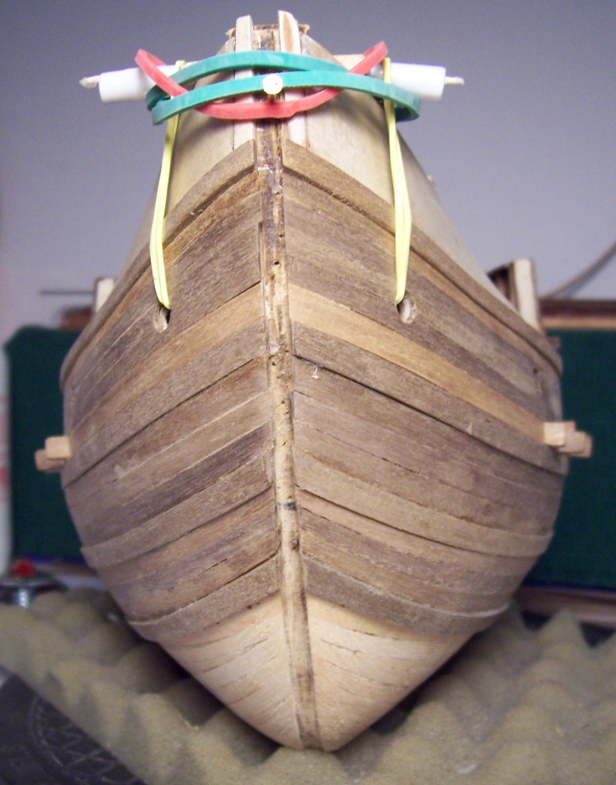
After total covering of the hull with the planking, next step was to cover the forward bulwarks with a kind of planking named "clinker work", as we can see in many contemporary illustrations:
Material for Clinker: wood thickness 0,5 mm.

Now we can try to tint the hull.
Continue....
-
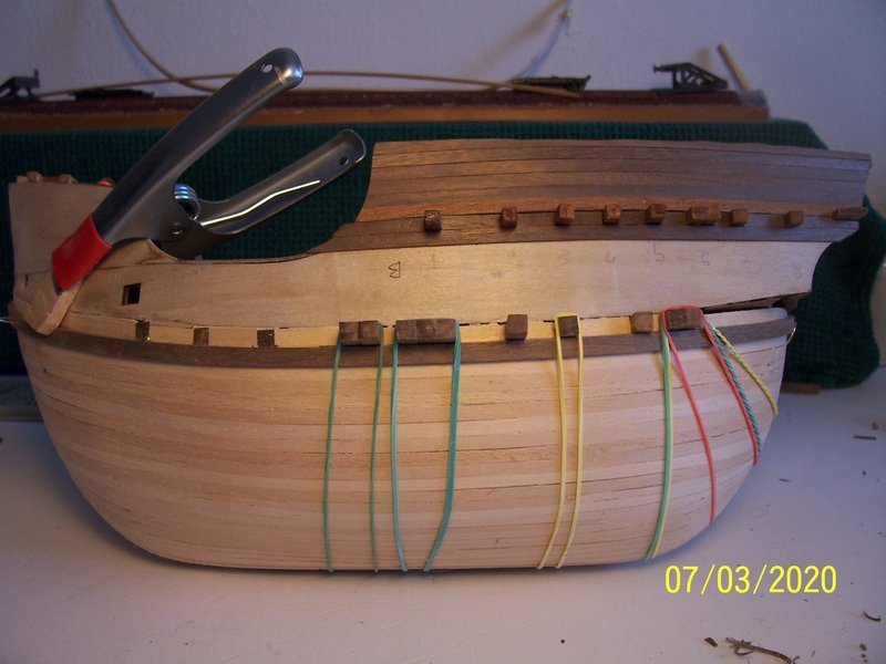
...we'll add three more courses of tapered planking:
As last wales, I used the remaining two strips 2x5 mm, one of which had been broken at the beginning of the work:

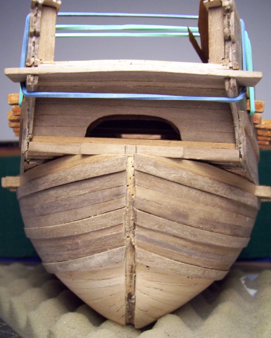

and now it remains only to complete the planking till to the keel:
Have a good continuation of your work...
Rodolfo
-
-
-
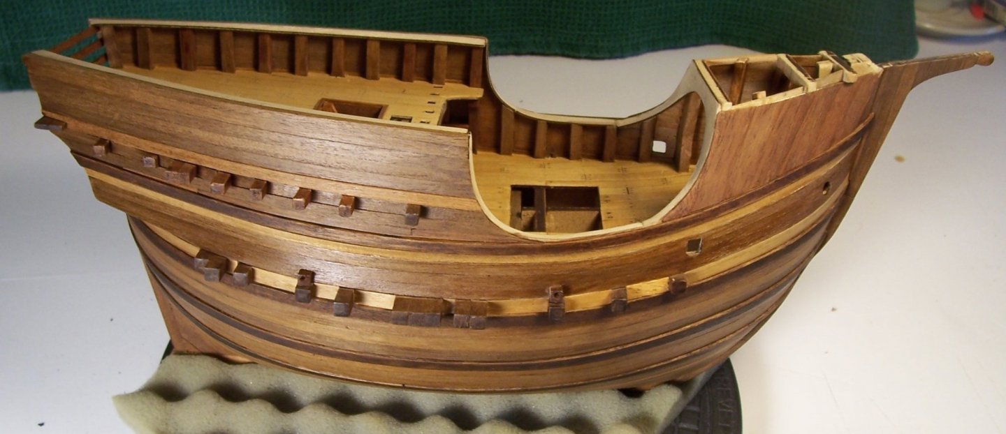
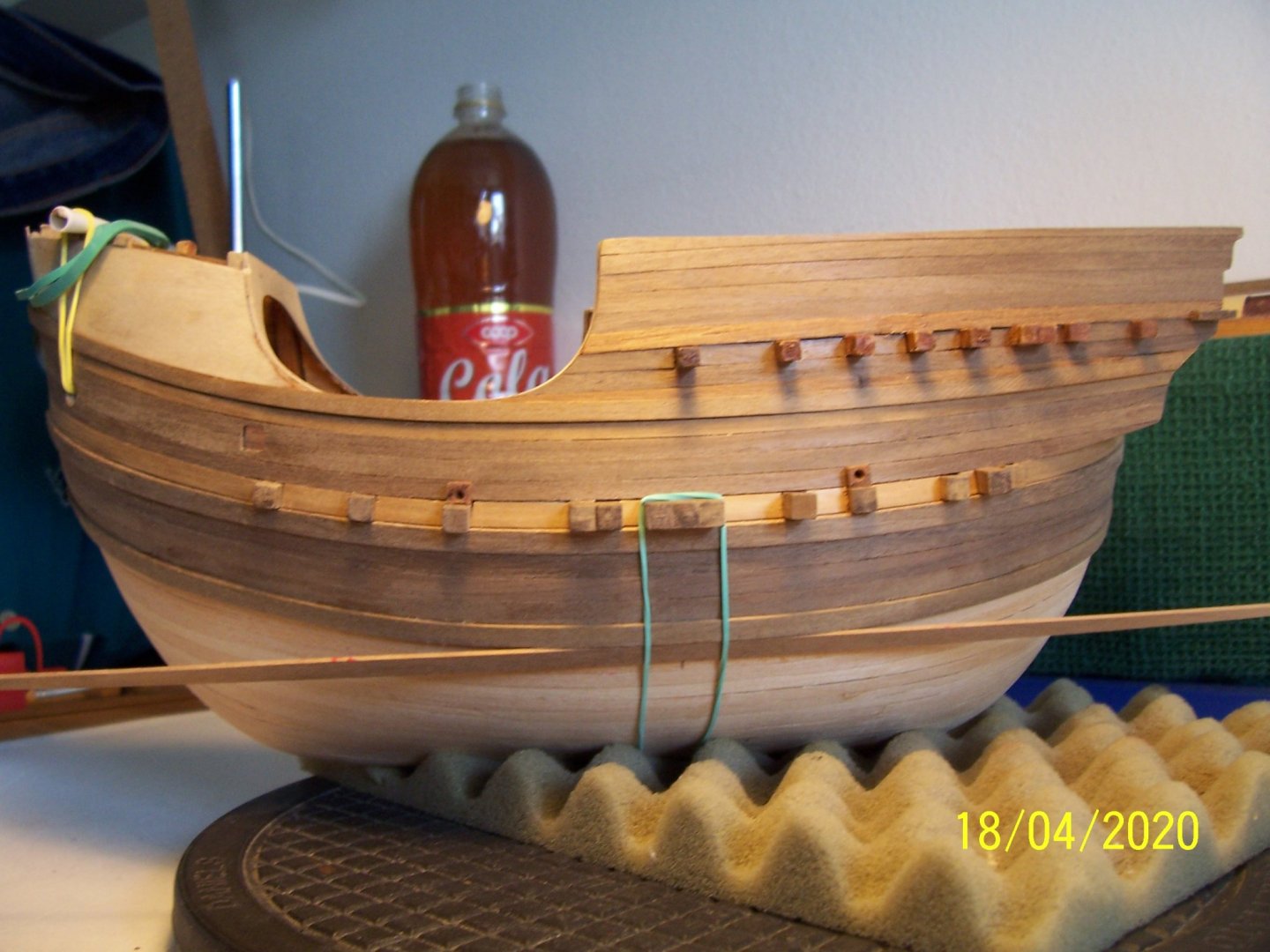
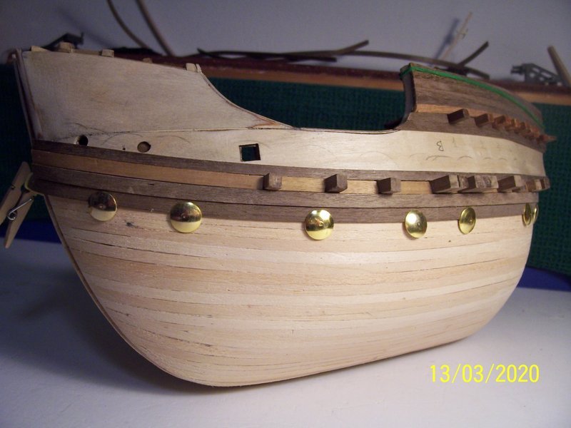
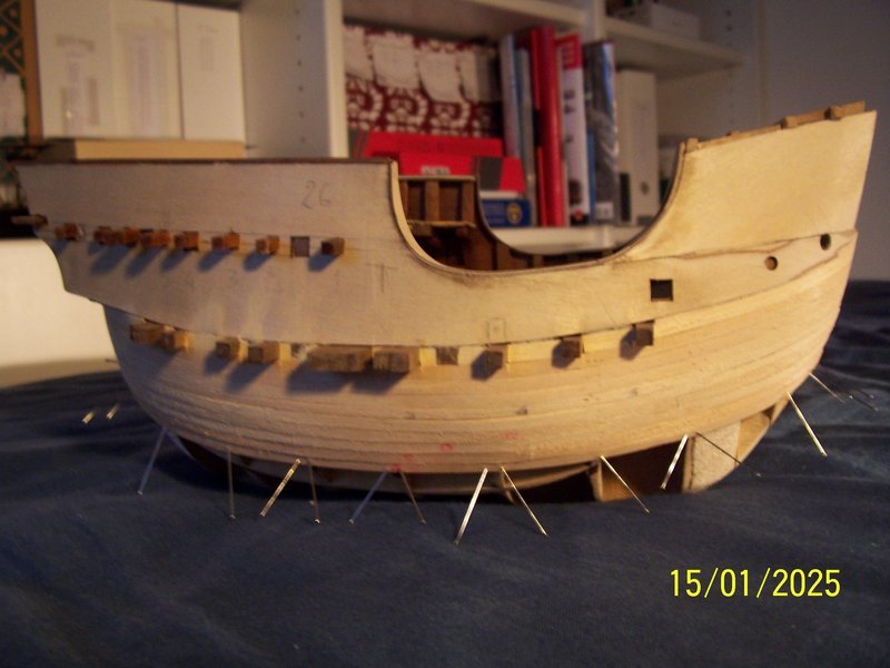
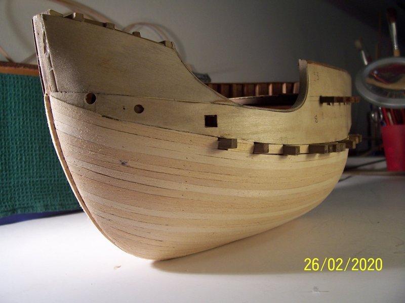
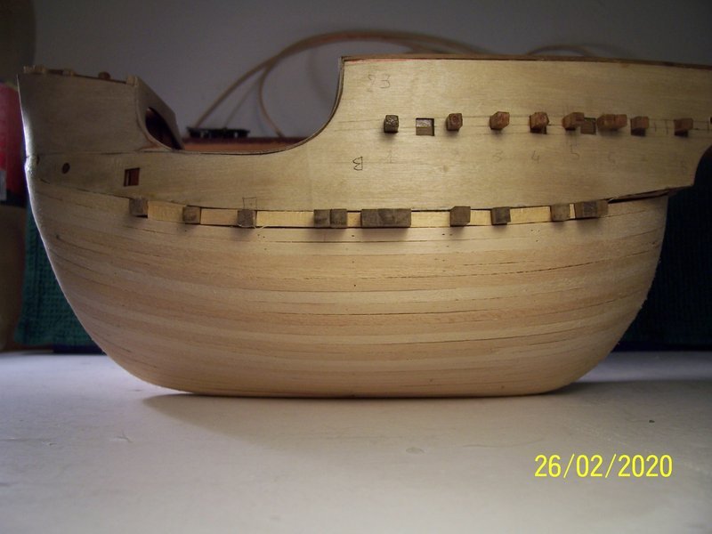
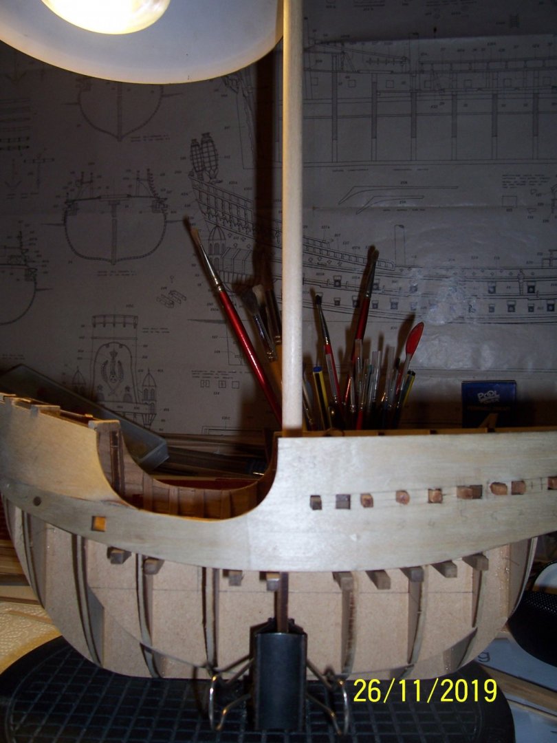
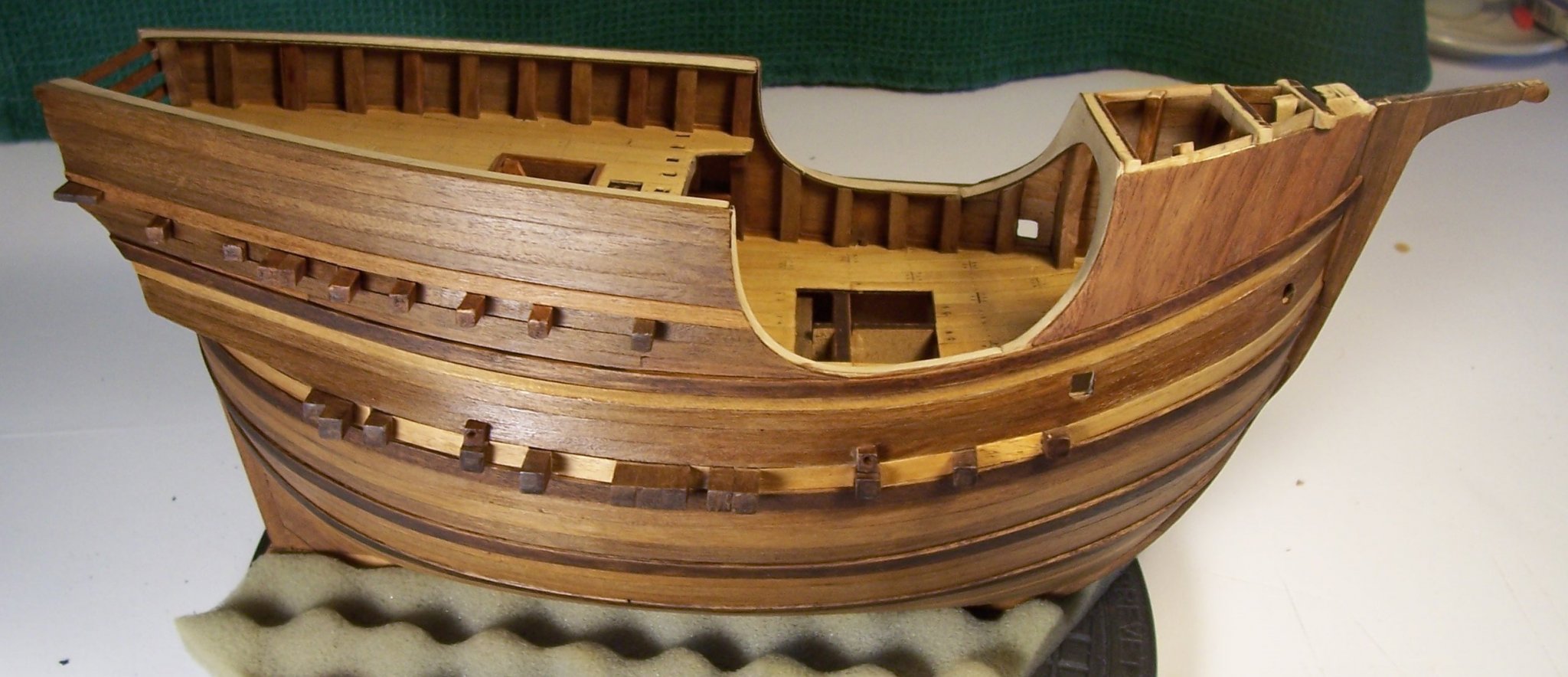
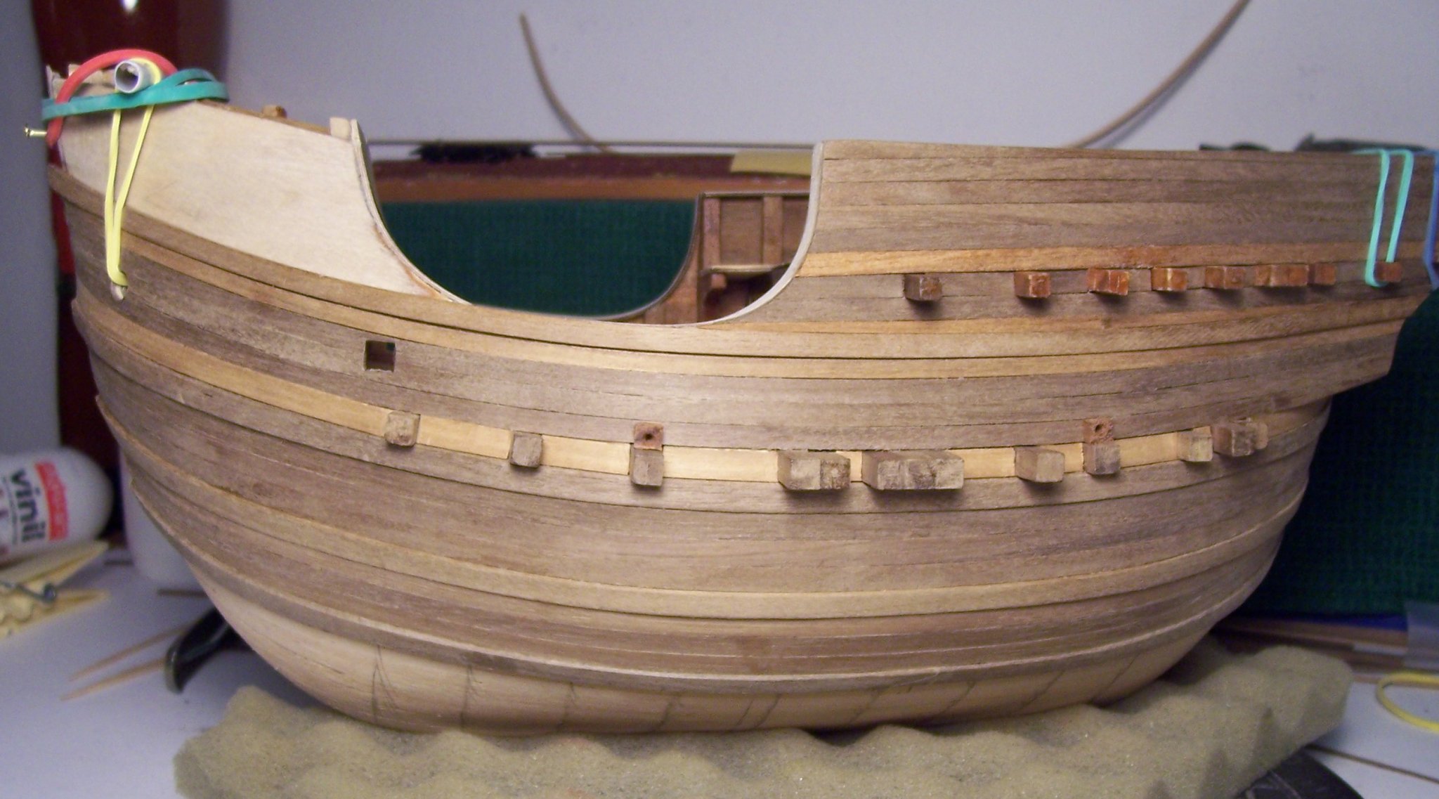
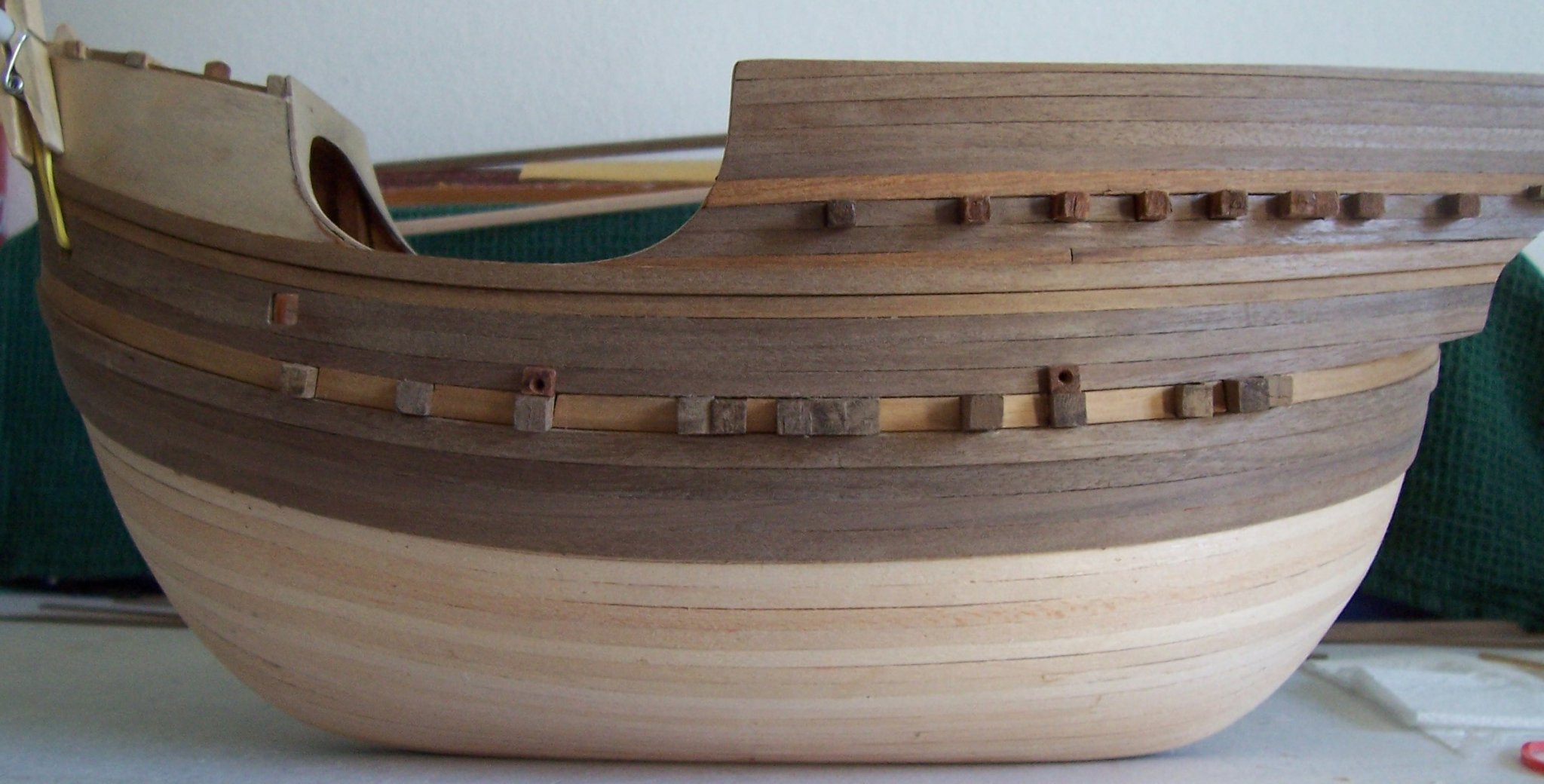
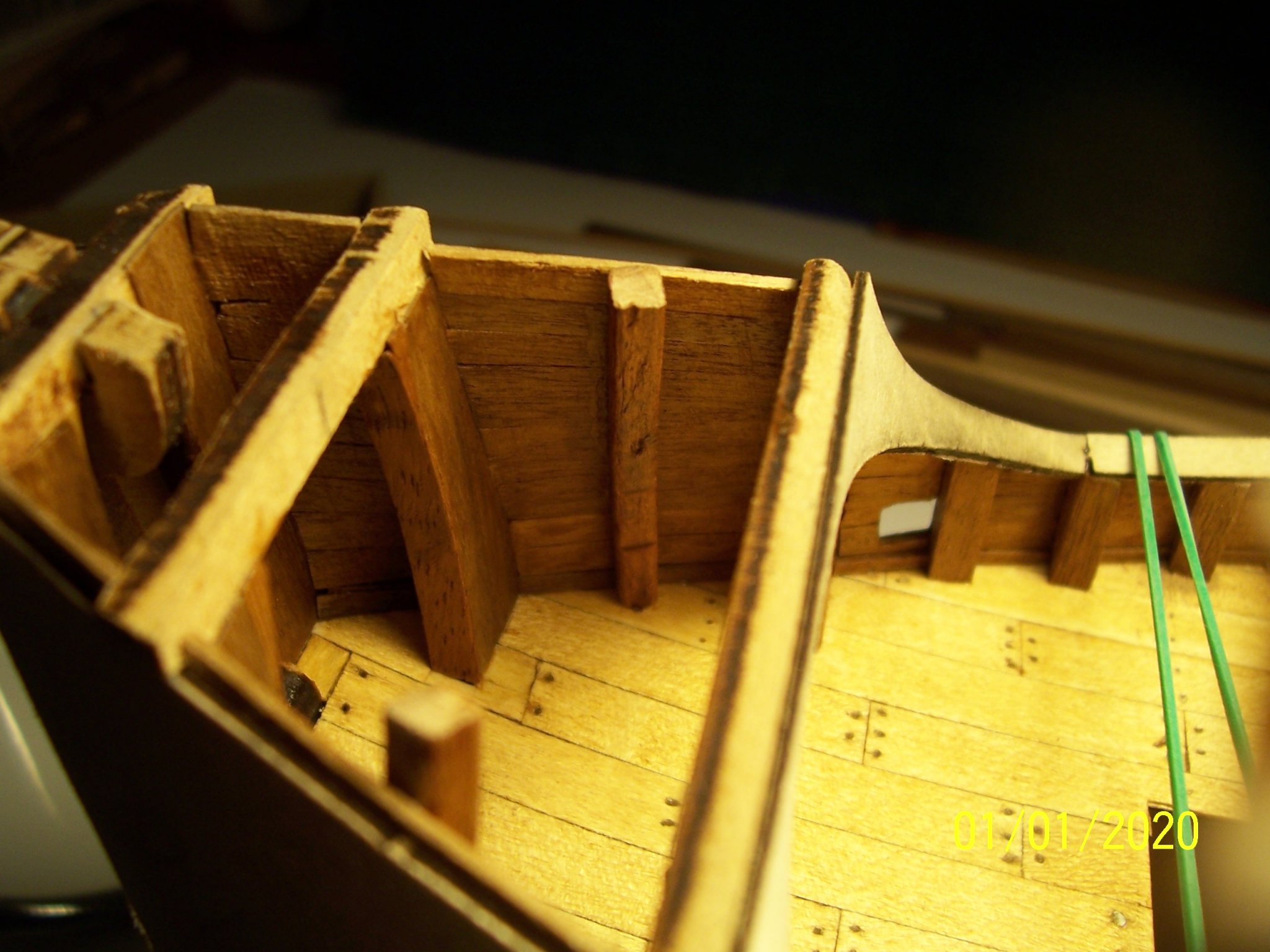
Hello everyone!
Before starting with second planking it could be better to cut the the protruding part of the beams, in order to rotate and glue them matching the course of the wales.
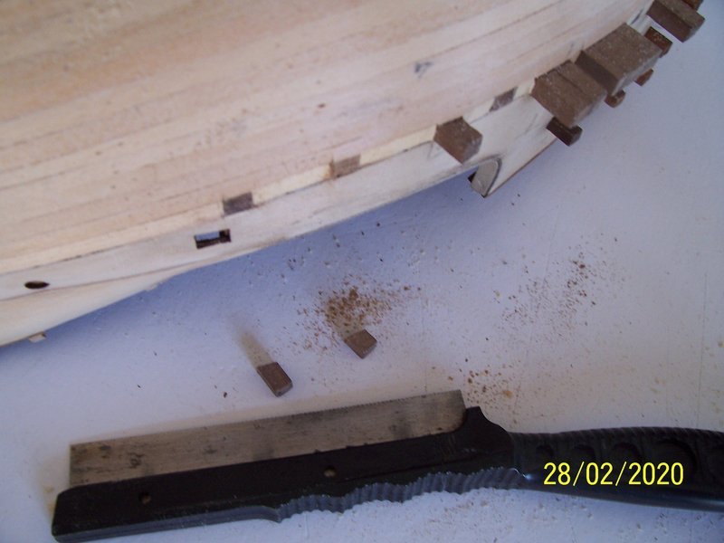
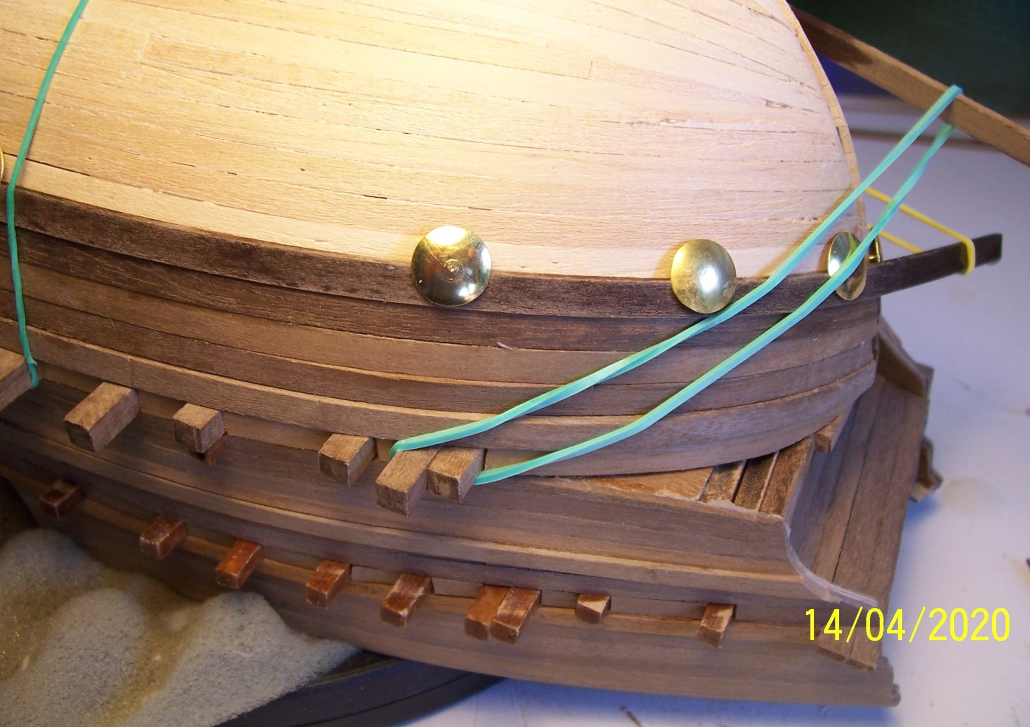
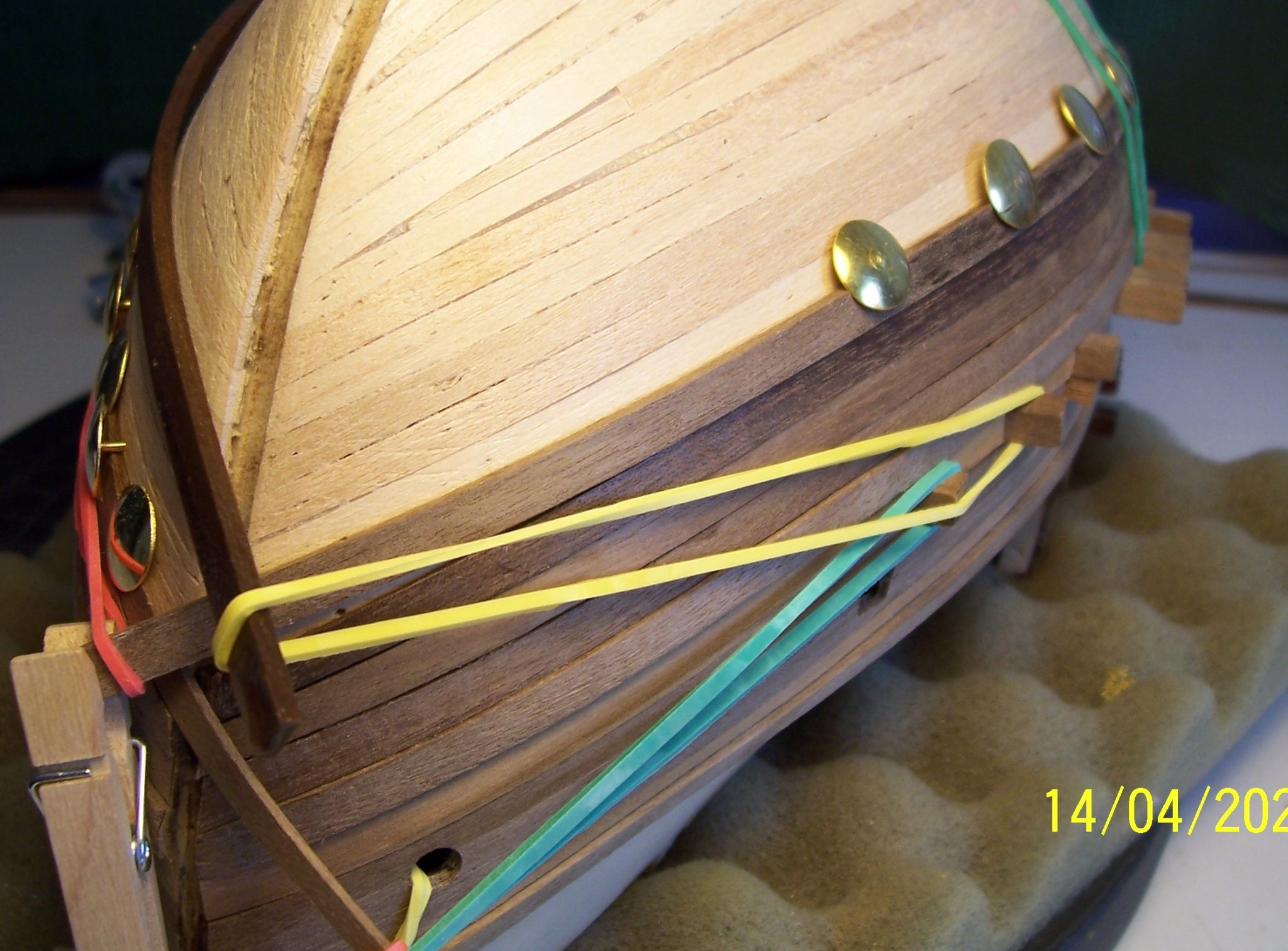
After that, the second planking made by walnut strips can start.
Usually people do it covering by the strips the whole hull and after gluing the wales, but In this way may be difficult the wales will follow in a perfect manner the course of the underlying planks.
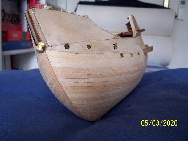
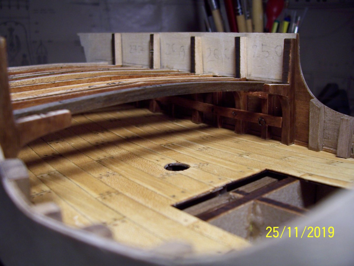
I preferred to glue the wales at first, starting with the one above the upper beams of the bulwark and followed by the other thinner strips:
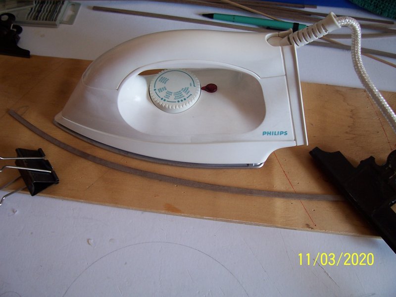
Till now it's quite easy. The other wales are more difficult to be positioned and it is preferably to bend them in both directions, using water and heat:
Besides, we can check if the groove for the keel has been correctly executed, using a 4x2 mm strip:

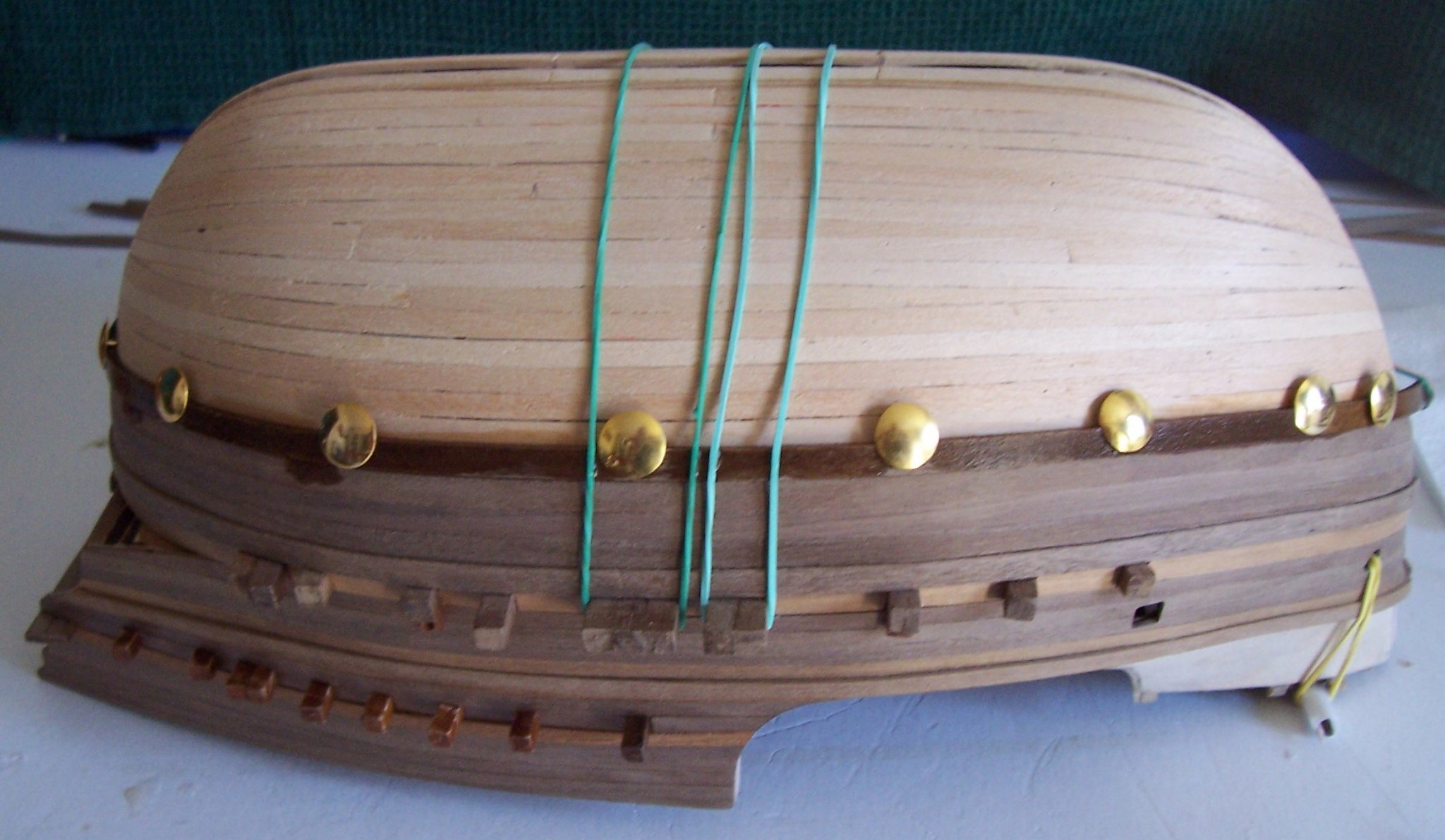
Now we can start with the second couple of wales, under the beams of the main deck; at this step, the accurate symmetry of the first planking is helping:
At the end:
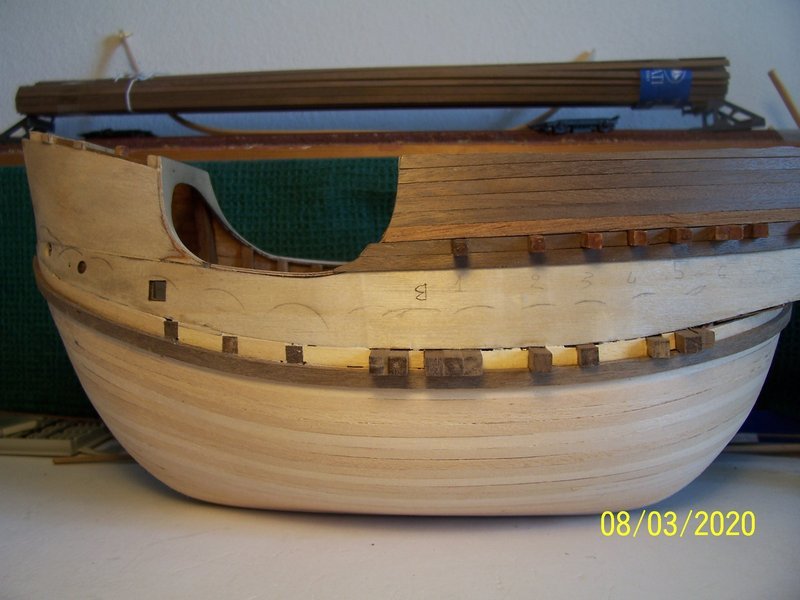
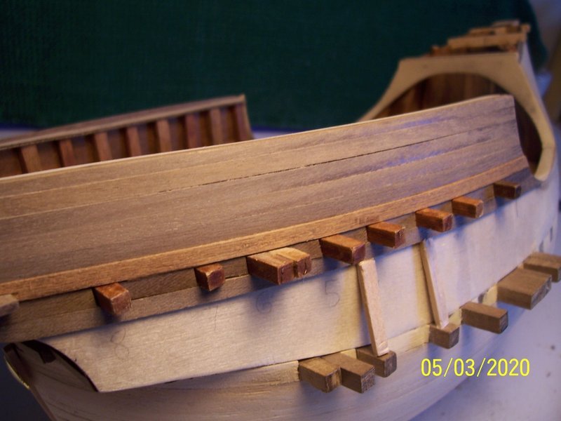
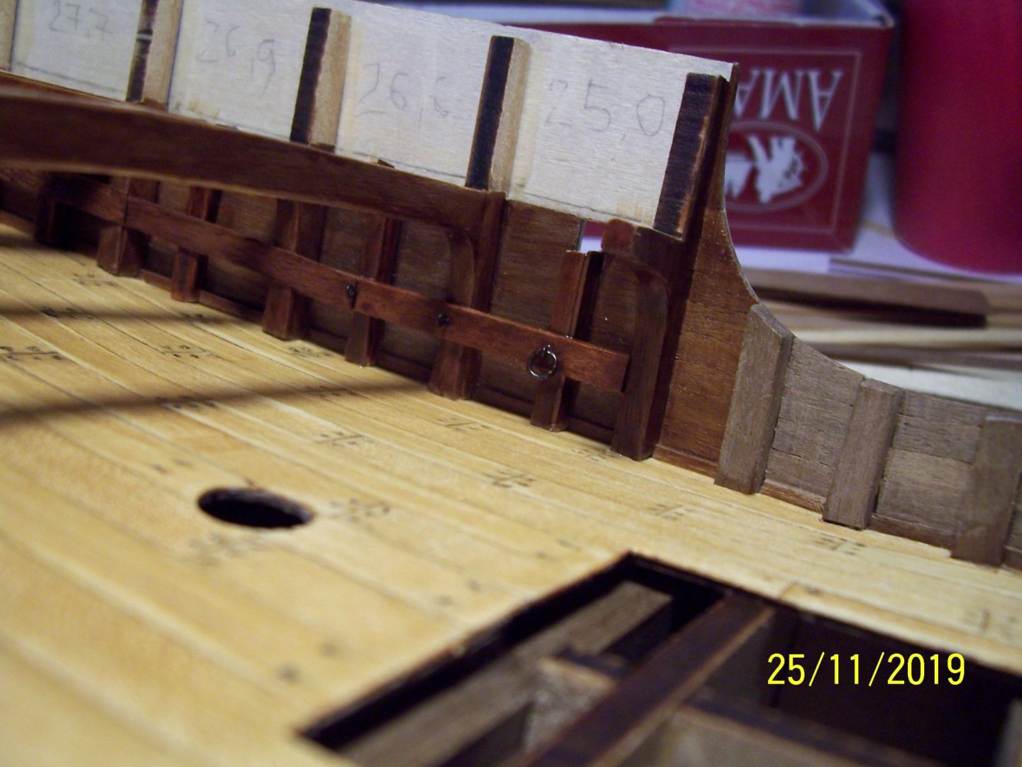
Now we can glue the ends of the beams we have cut at the beginning, following the course of the underlying wale:
Next step will be planking the areas between the beams; I've used a strip with a lighter color. After that, the planking will continue upwards as usually till to the next upper wale and also downward:
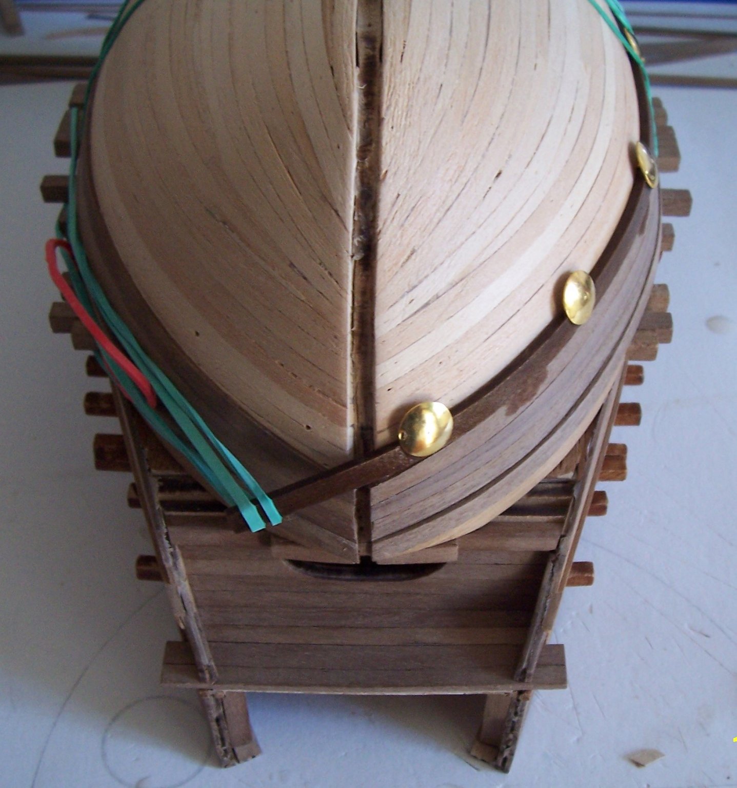
The upper wale must match the curvature of the bulwark:
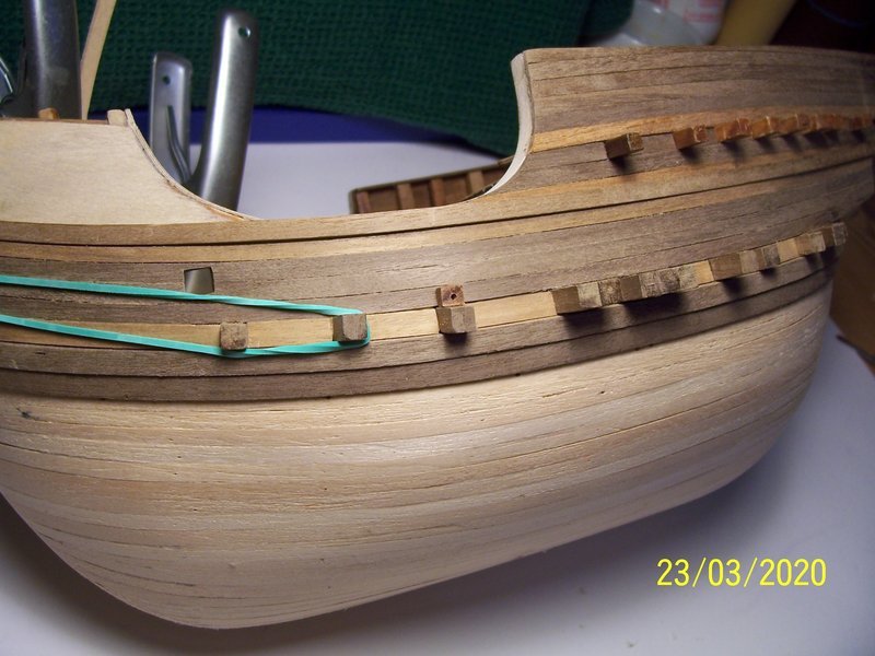
I've also added the scuppers.

Obviously the same work has to be done on the other side of the hull.
I hope I haven't been too verbose...
A greeting to all of you
Rodolfo
- GrandpaPhil, PietFriet, J11 and 5 others
-
8
-
Very interesting ship and well done work.
Rodolfo
- mtaylor, coxswain, Keith Black and 1 other
-
4
-
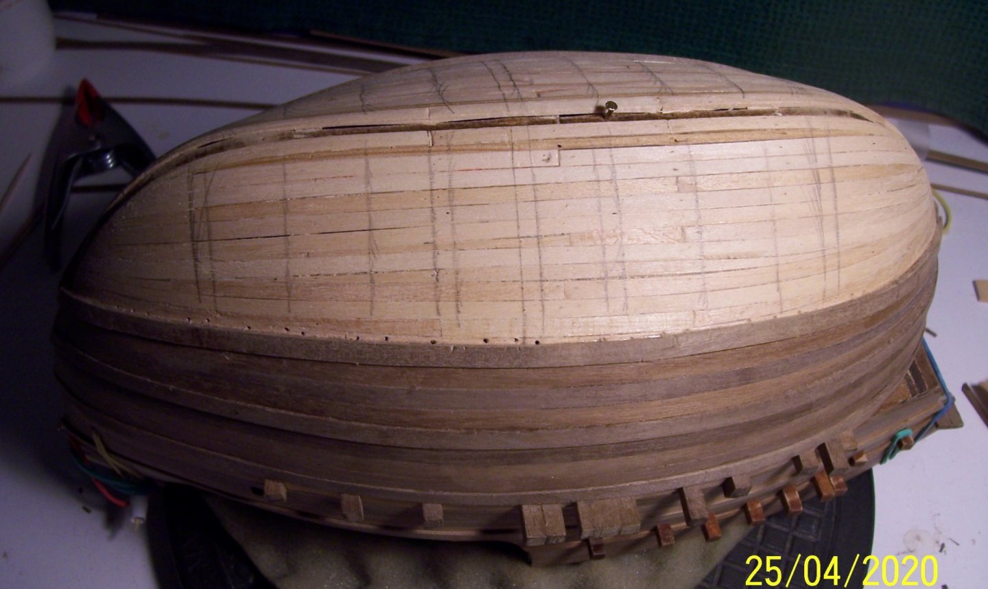
I've tried a further reduction of the pictures.
The first planking of the hull will be completed applying one strip at a time on each side on it; the lime wood strips are very easy to work:
As I wrote, it is very important to maintain the symmetry, because the second planking in Walnut strips will be not as usual.
Have a nice afternoon,
Rodolfo.
-
Dear all,
I've tried to post smaller pictures than previously, in order to save space.
After having moved the upper and lower beams, it is time to begin the planking of the hull. The first planking is made by Lime Wood 2x4 mm, very good for bending forward and upward, too.
The first strip has been positioned underneath the lower crossbeams, in order to make easier the correct positioning of the upper planking strake, among the beams.
In front of the third frame, I've added a support of balsa wood, in order to obtain a better curvature of the strip (otherwise it wanted to be more linear)
It will be very important to maintain the maximum of symmetry on both the sides...
Continue...
Rodolfo
- GrandpaPhil, KentM, Baker and 3 others
-
6
-
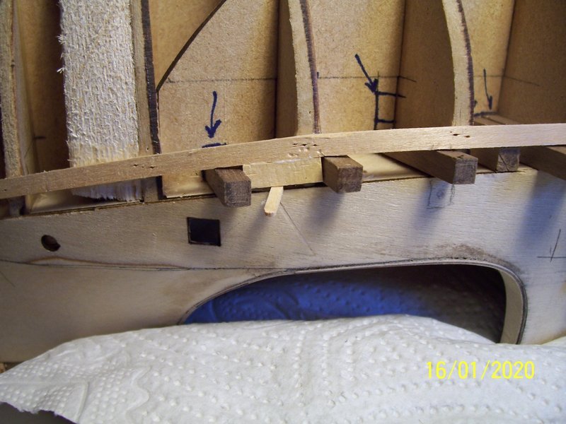
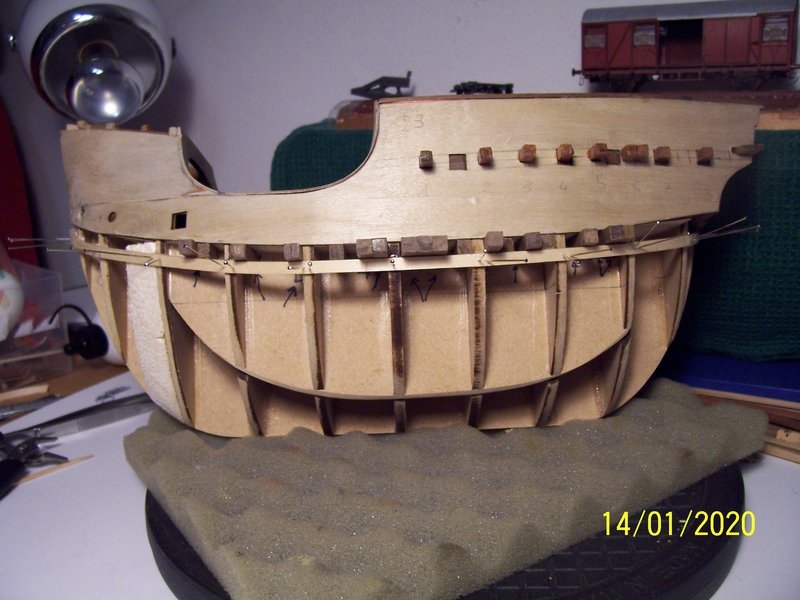
Hello to everybody,
at the beginning I started following exactly the instruction. After having collect some documentation I decided to change some things and therefore I had also to cut/move/add the beams of the main deck.
The first picture shows how I did that, marking the positions of the new beams.
The second picture shows how my ship (I hope) will be.
Good work,
Rodolfo
.jpg.813267cd24b774f16a2372980e338941.jpg)
- GrandpaPhil, KentM, Baker and 2 others
-
5
-
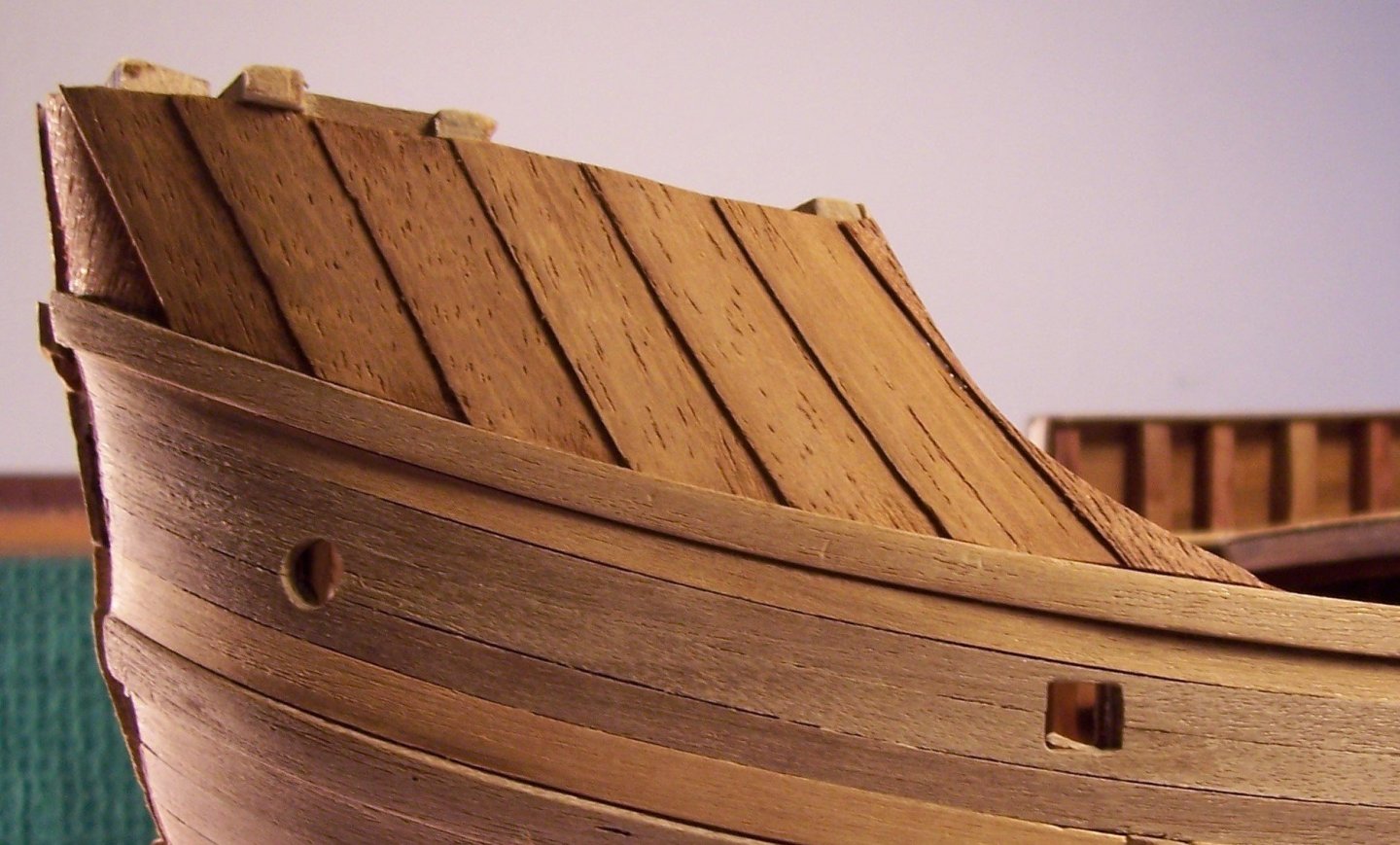
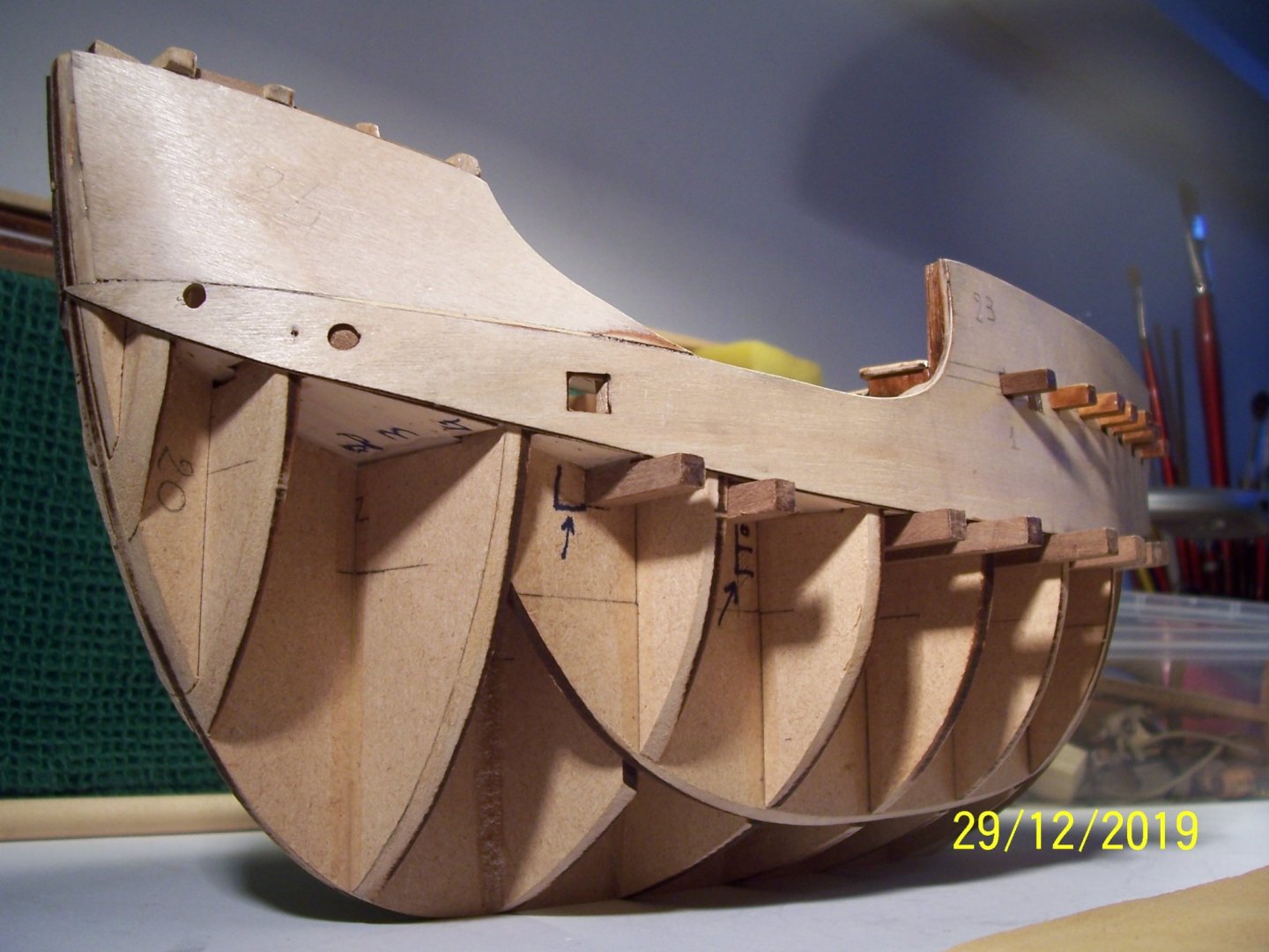
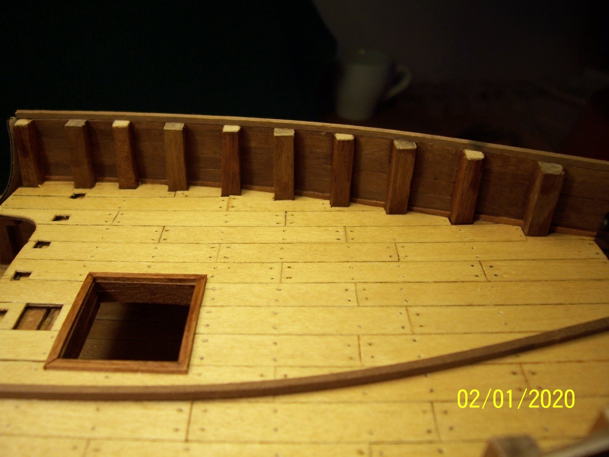
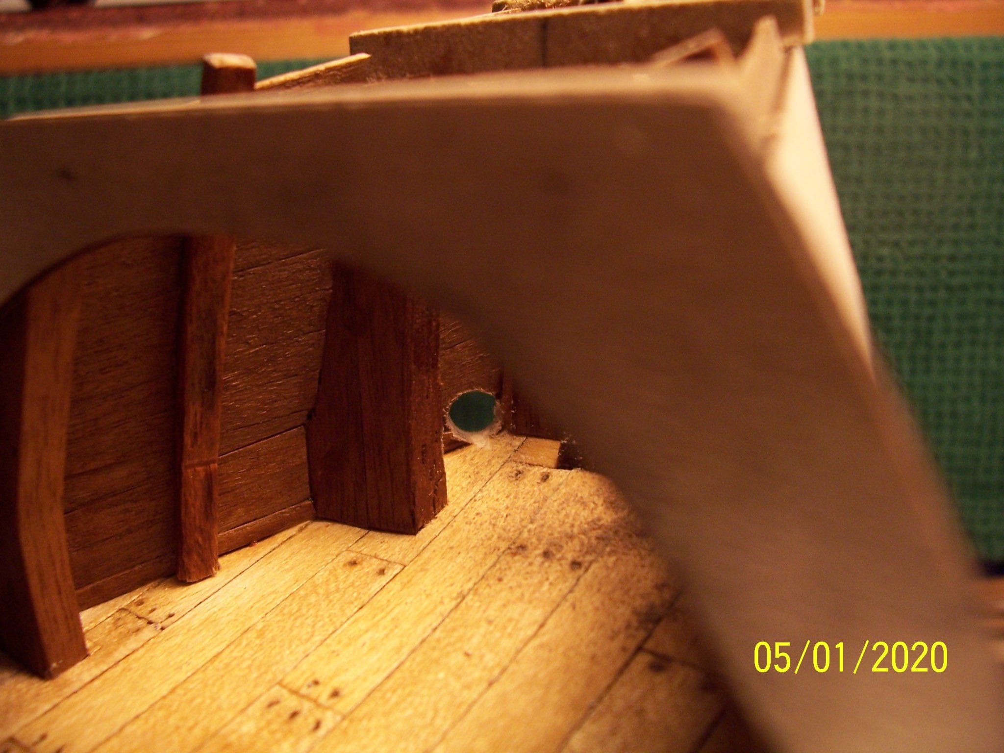
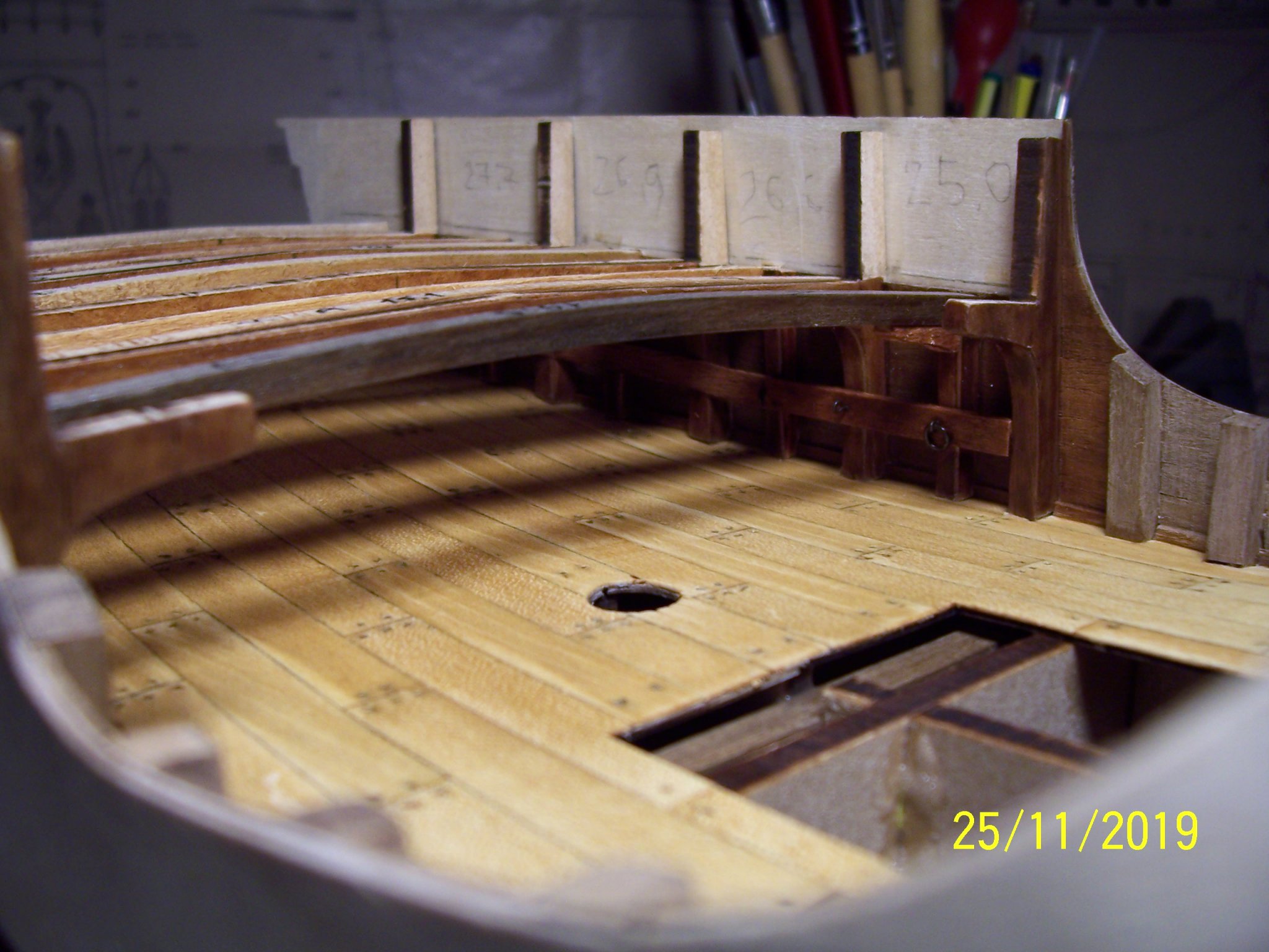
Dear all,
the first picture shows how and where the holes for the beams of the upper deck were opened;
the second, shows the upper deck in its initial appearance,
the third shows the insertion of Water Ways ( done on both the decks),
the fourth shows the addition of new frames among the older ones,
the fifth shows the upper deck almost finished,
and finally the hawse holes.
Good sawdust!
Rodolfo


- BLACK VIKING, GrandpaPhil, J11 and 3 others
-
6
-
Hi Steven,
I knew the votive ship, but your pictures are super detailed, many thanks!
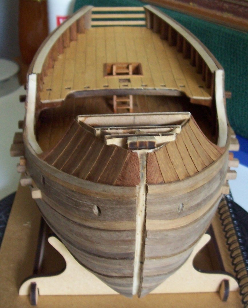
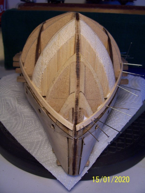
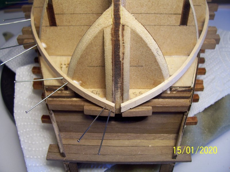
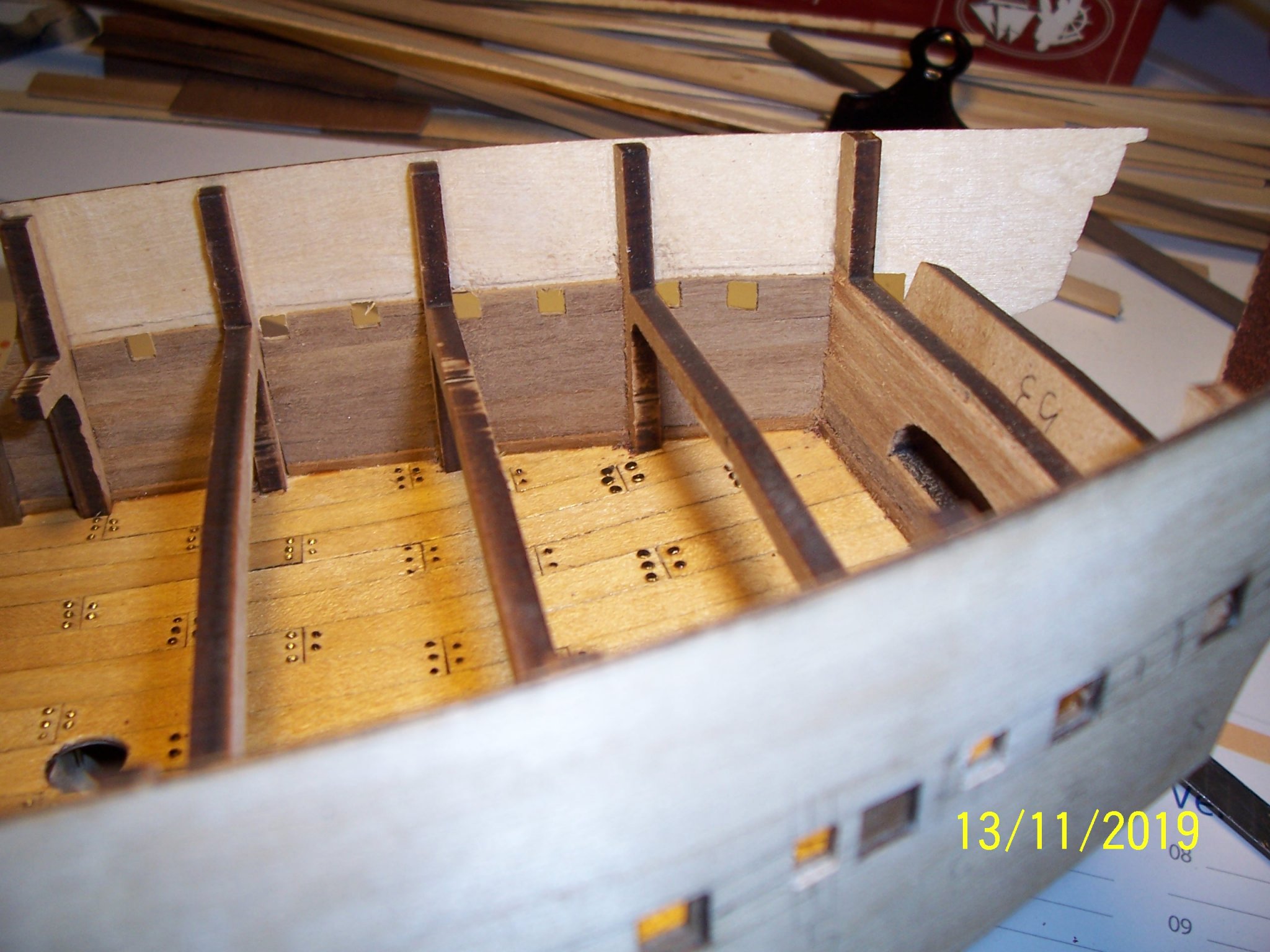
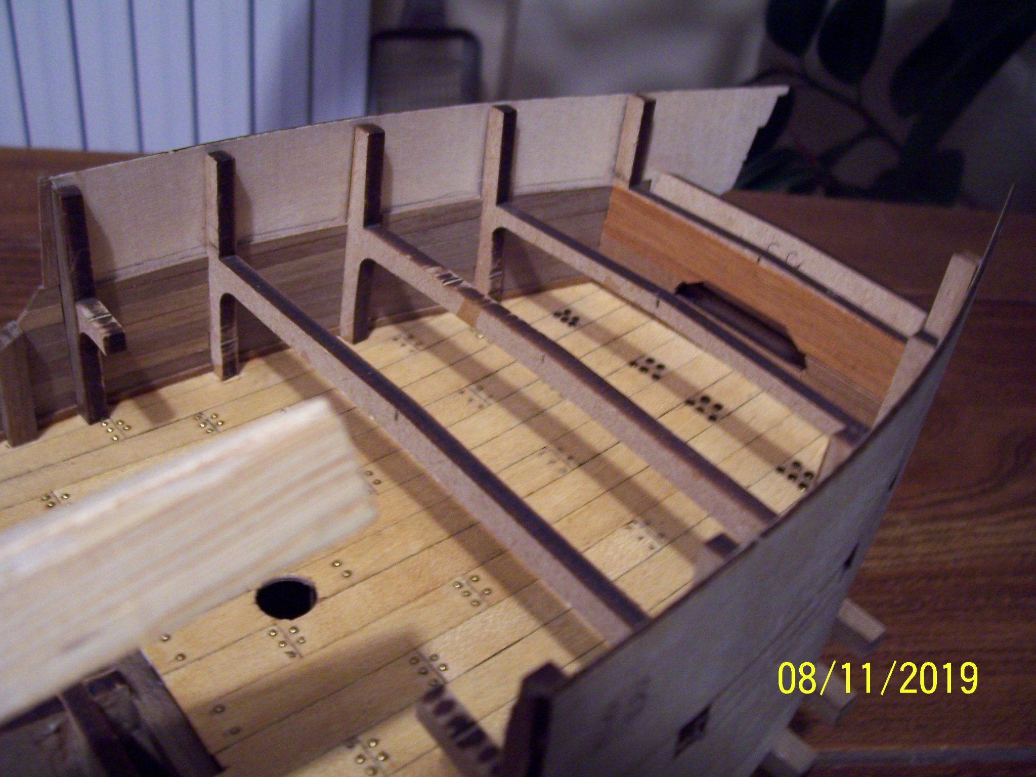
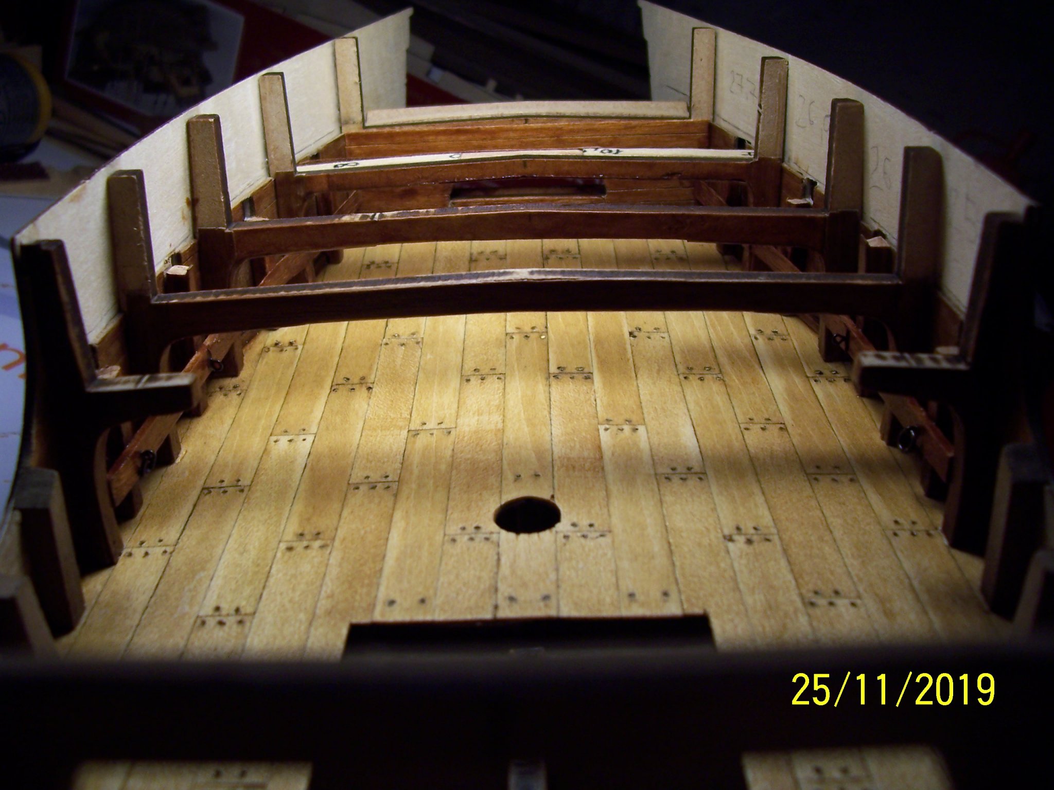
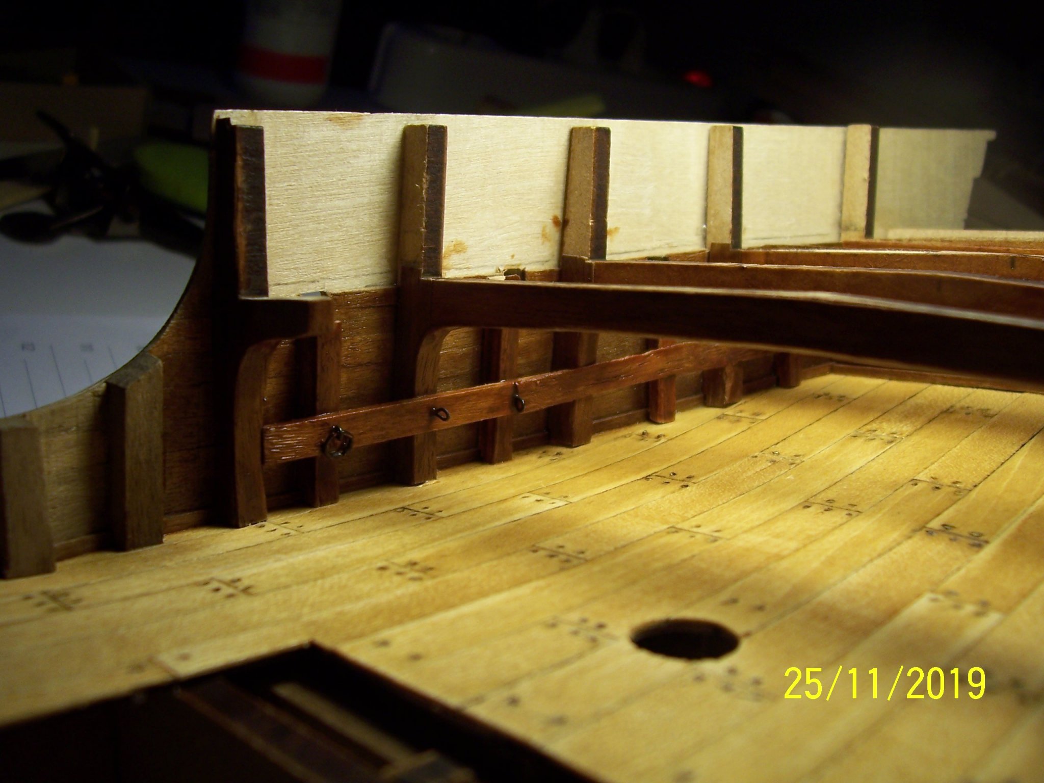
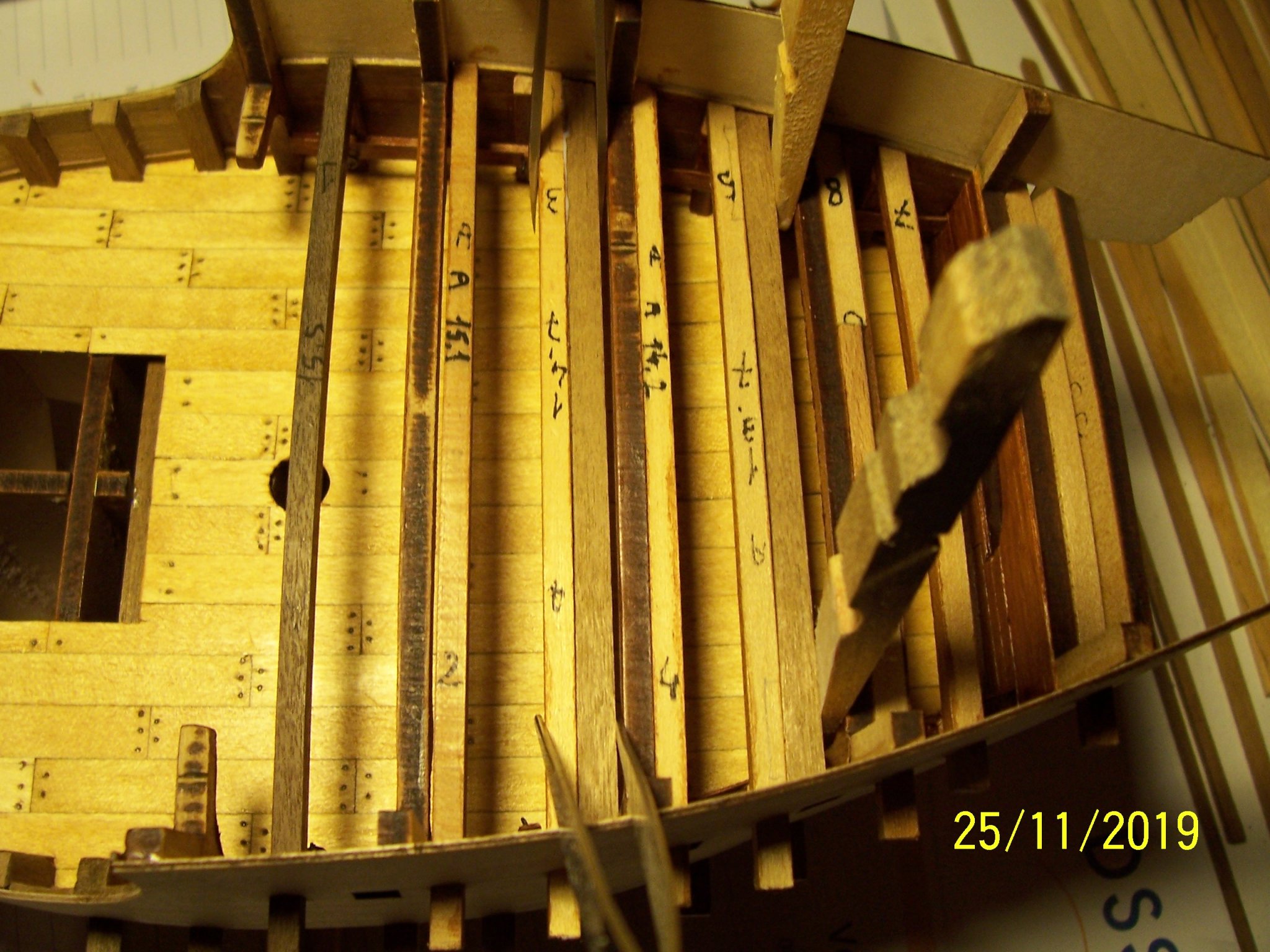
Now I'll show some pictures about the inner of the ship, taken when the work was at the beginning; I planted nails on the planks, but they were too flashy and after I removed them.
As the frames are too widely distributed, I added more feints ones among them and a horizontal support table with eyebolts and rings.
Finally I've added the new cross beams having a smaller section and a more accentuated bend to support the upper deck.
Good work!
Rodolfo


- chris watton, Edwardkenway, KentM and 3 others
-
6
-
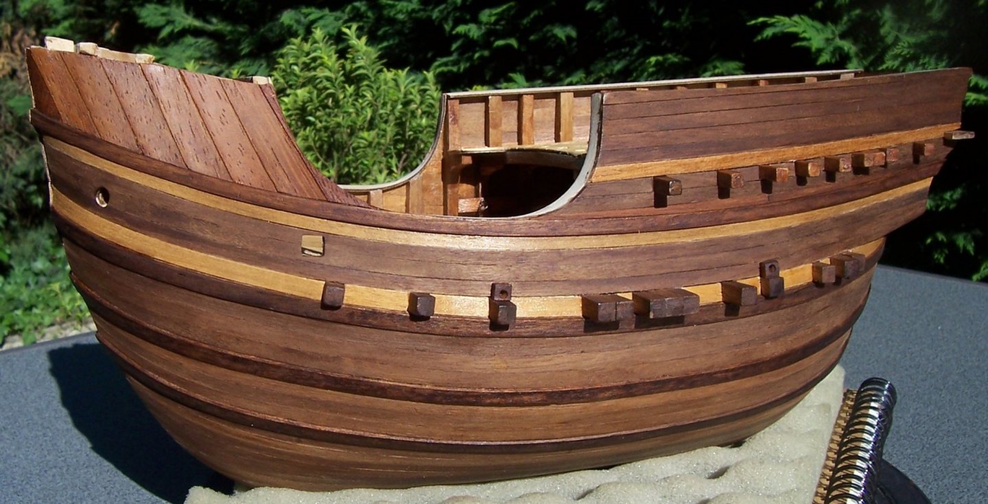
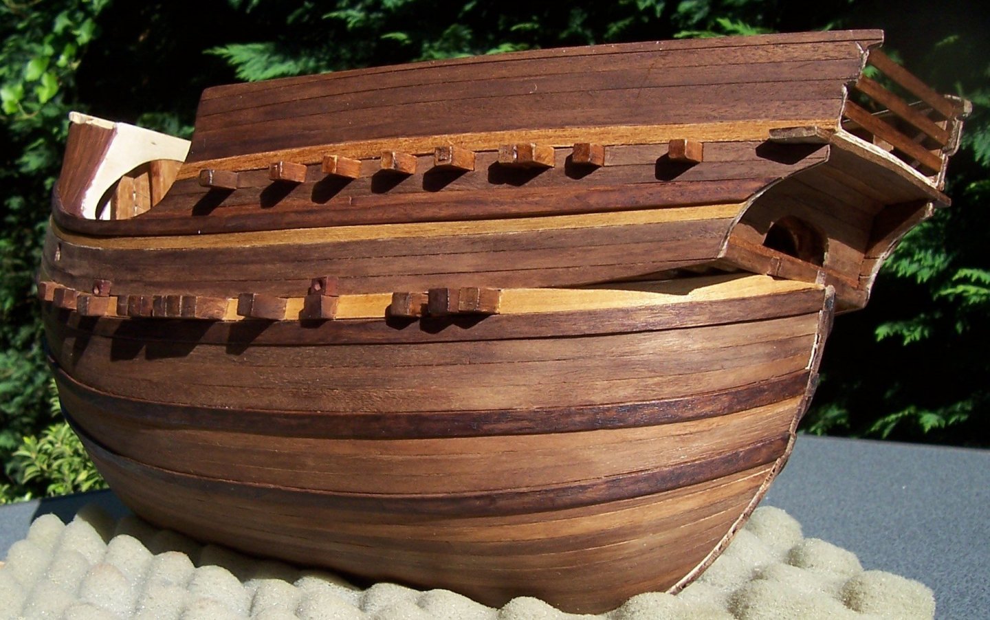
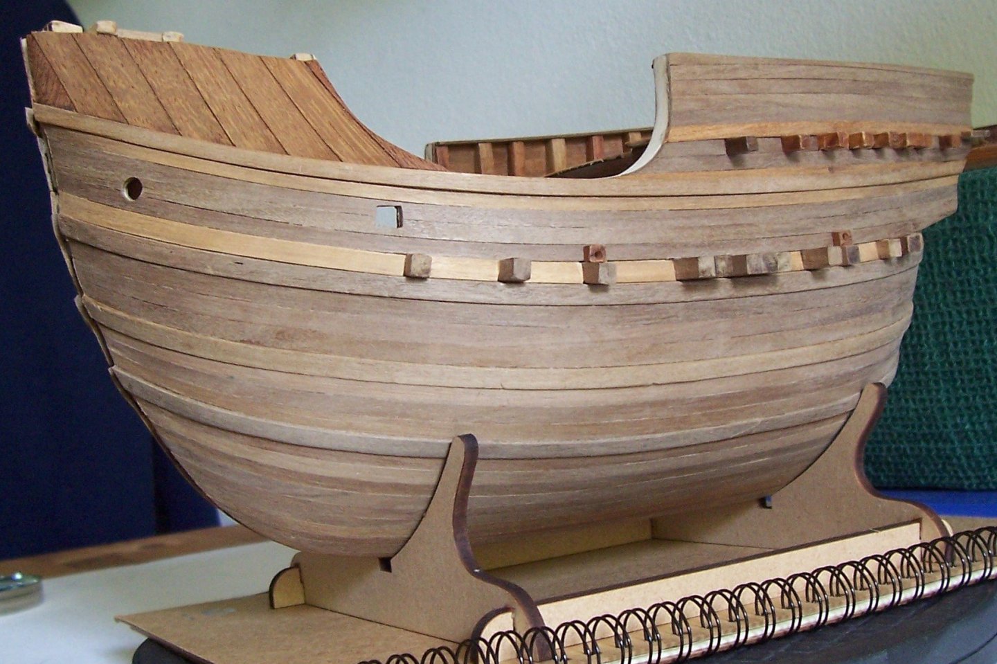
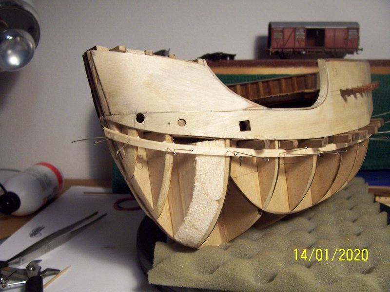
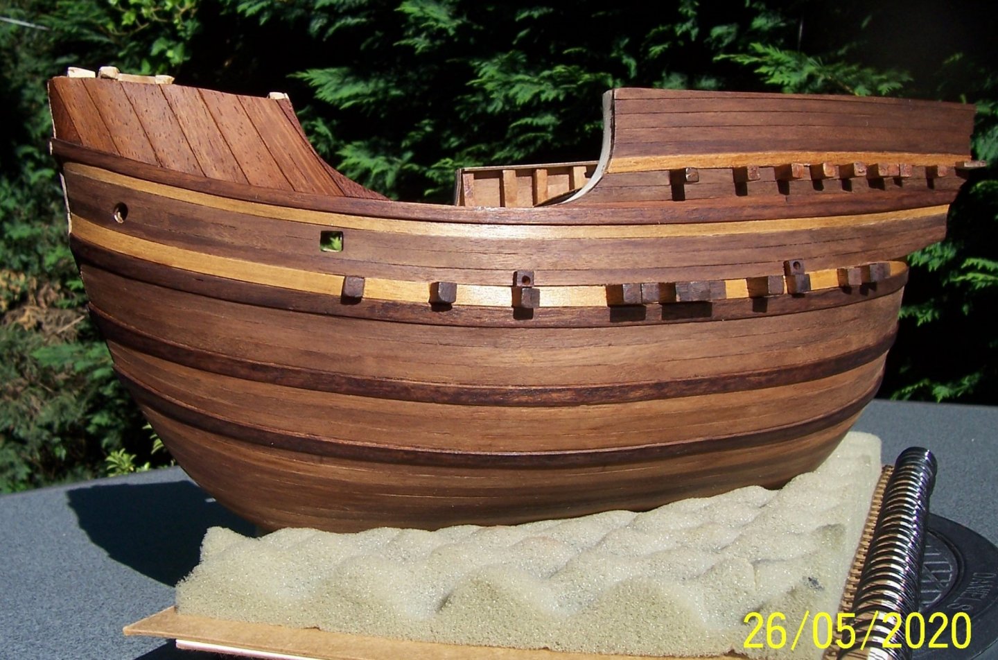
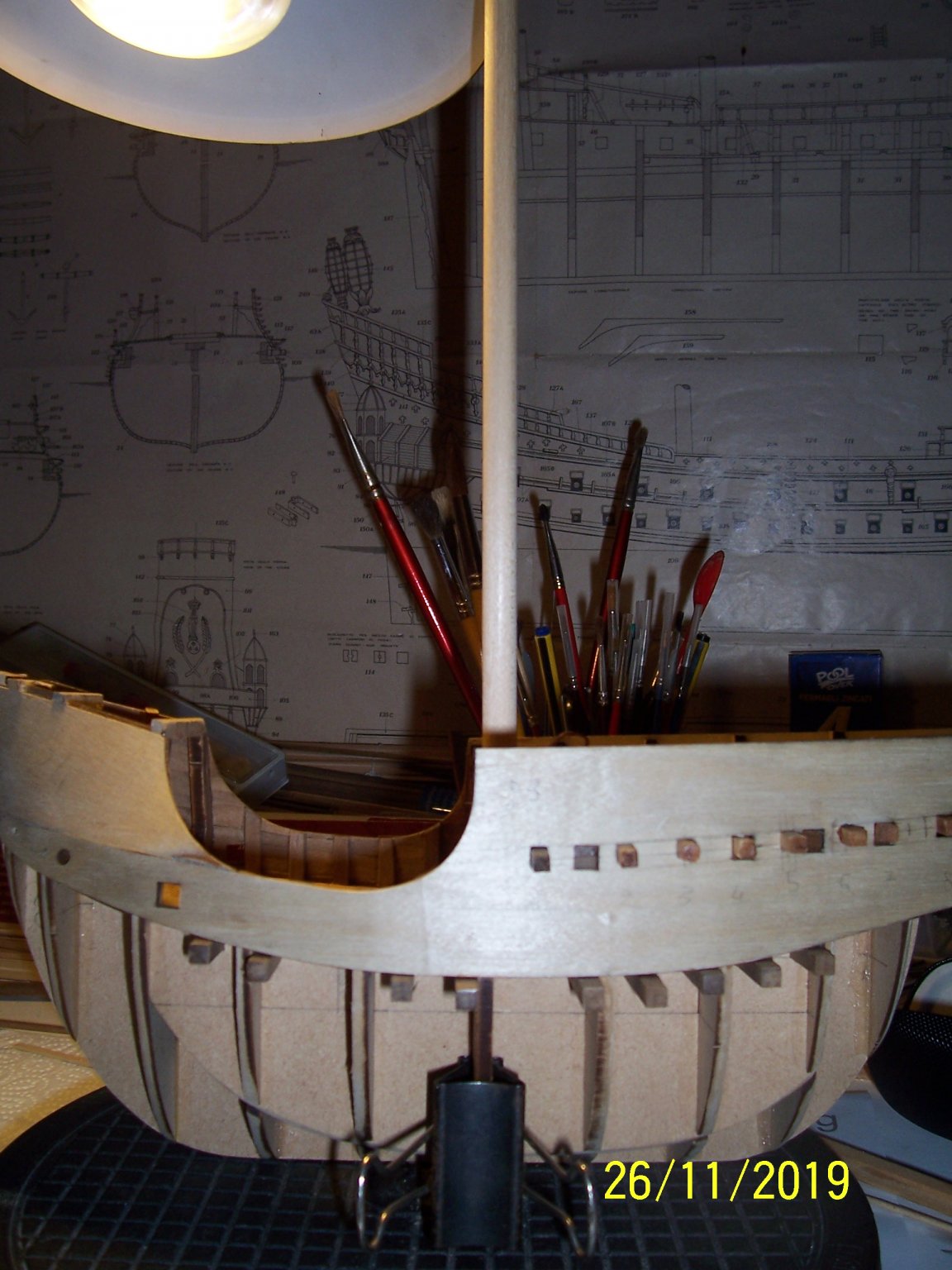
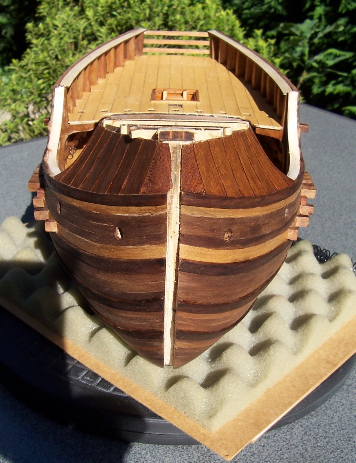
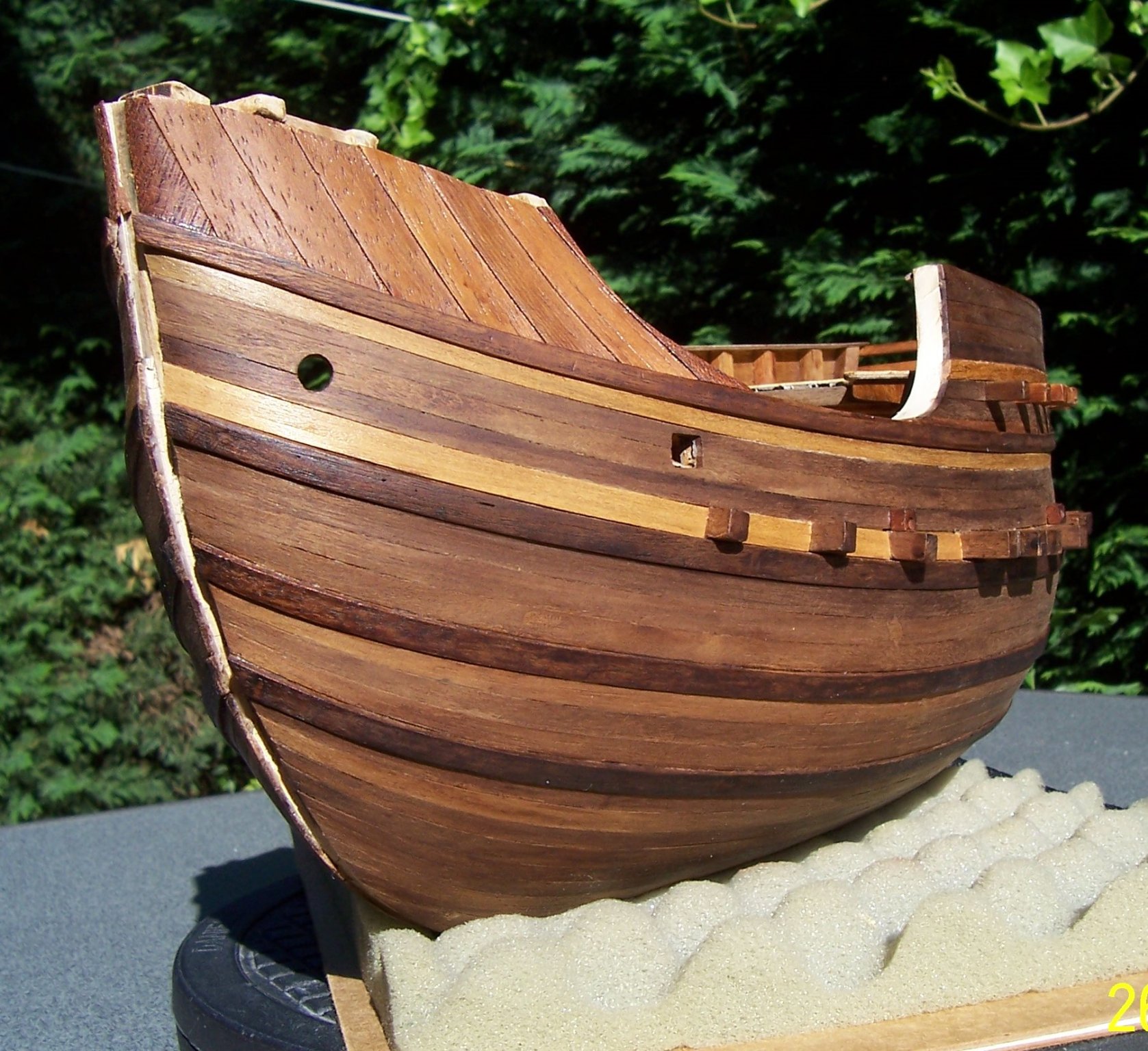
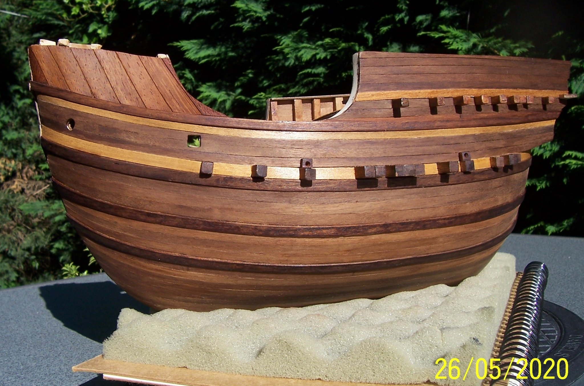
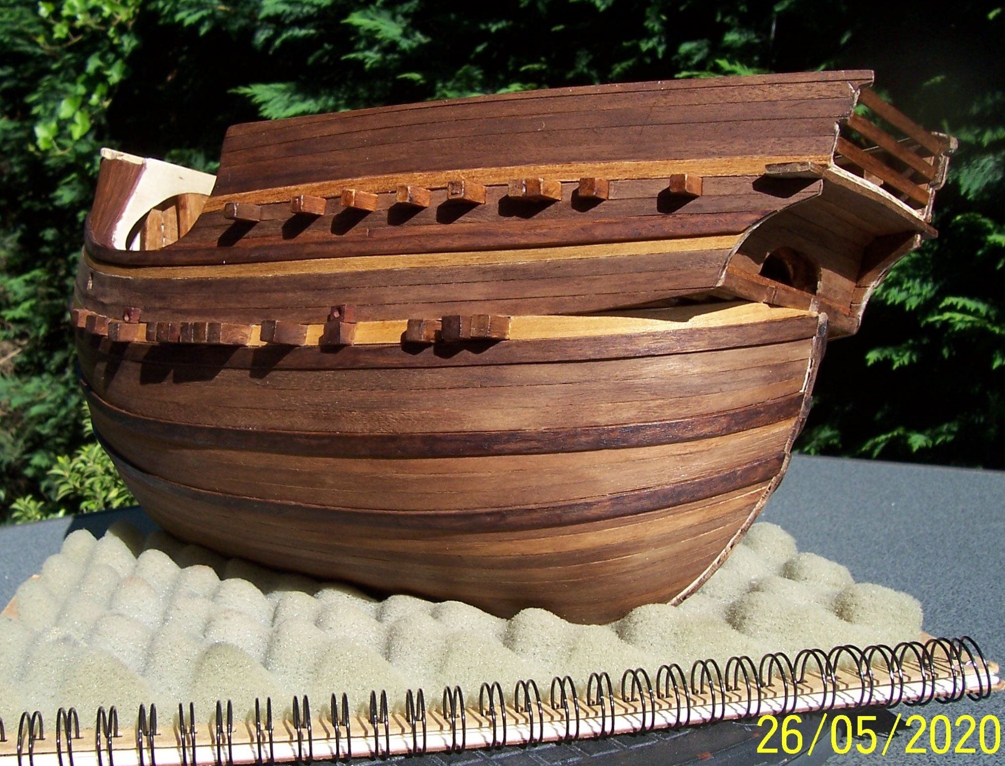
Hello to everybody!
I will post some pictures of the ship as it appears today, after almost eight months of work. These explain the changes I made with respect to the AMATI's model:
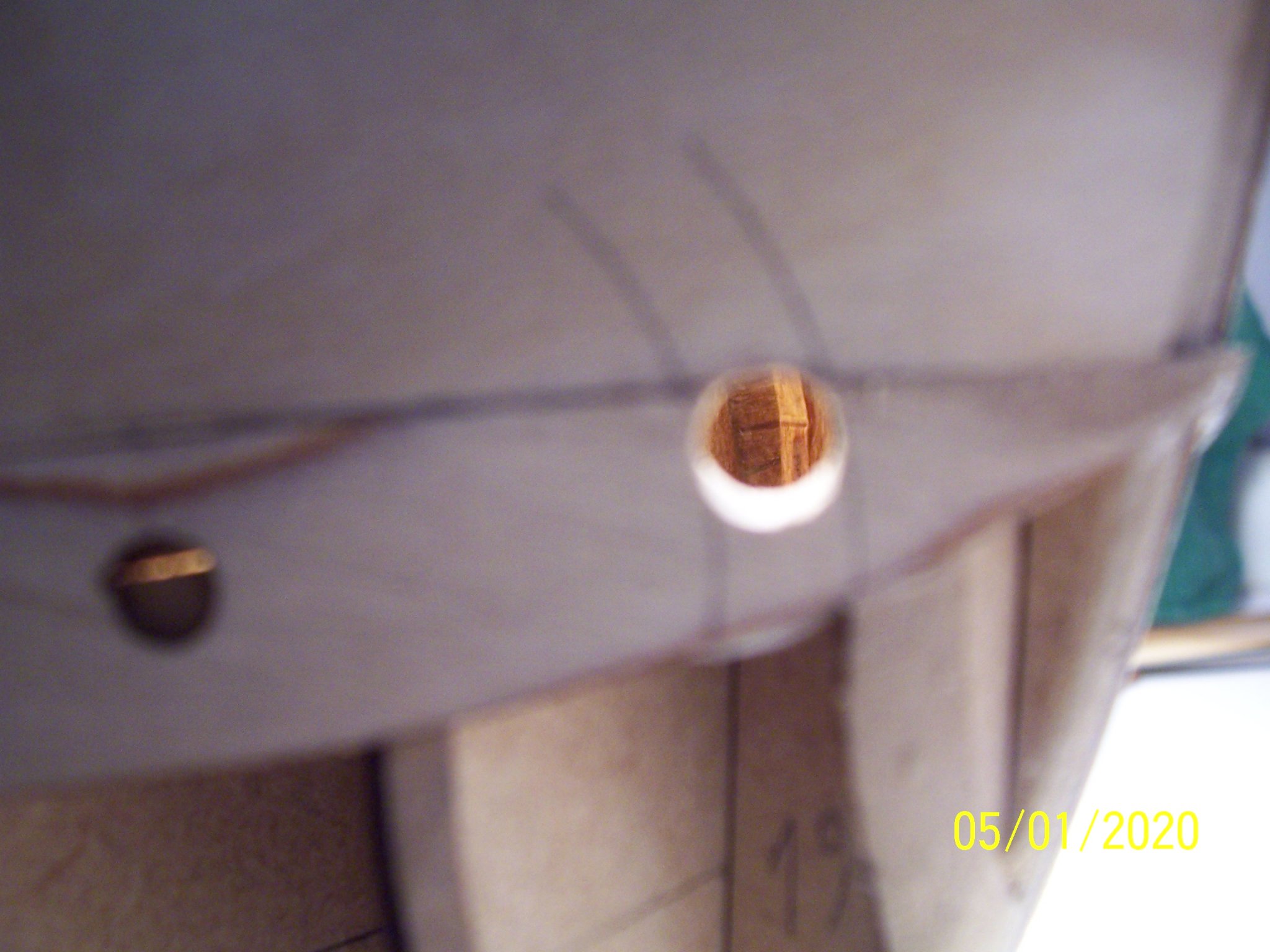
1) the hawse hole positioned further ahead.
2) the sides of the bow castle planked using "Clincher working".
3) the upper and lower cross beams having different sections, more numerous and differently positioned.
4) Five top-timbers (or wales), instead of four, differently positioned.
5) Added the scuppers.
At the end, the result is quite different from how it had been assembled by the manufacturer.
Next post, some pictures of the interior in today's state.
Good sawdust!
Rodolfo


- KentM, Edwardkenway, Ondras71 and 8 others
-
11
-
A warm "thank you" to John, Mark, Harley and Vaddoc!
Hi Harley, unfortunately I started this work eight months ago and I've almost completed the hull: therefore I've already made my mistakes! Undoubtedly railways models need much less time than ships, but patience is always requested and I have a lot of it ...
Today I will add some photos of the ship as it appears at the current time; later I will document the various stages of processing, so that future builders can do it better than me.
Good wood sawdust at all the people!
Rodolfo
-
-
Greetings to all the shipbuilders in this forum.
I'm sixty-five years old and the last sixty I dealt with model railways.
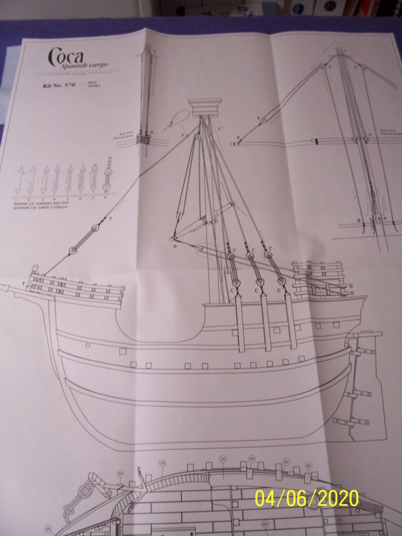
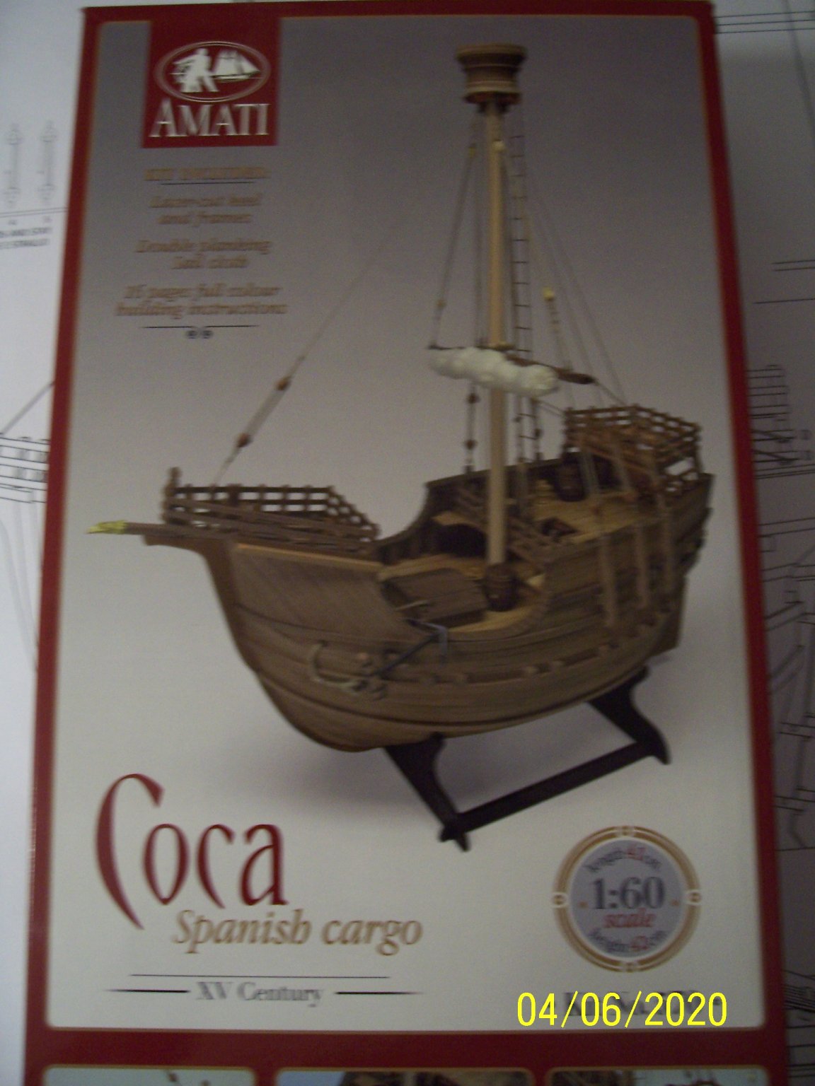
Few months ago I decided to do another attempt in shipbuilding (the first was the Golden Star when I was fifteen) and I chose the AMATI's Coca, because she's very nice and seems easy (but I realized it wasn't so for me, may be for other people more skillful).
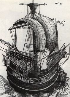
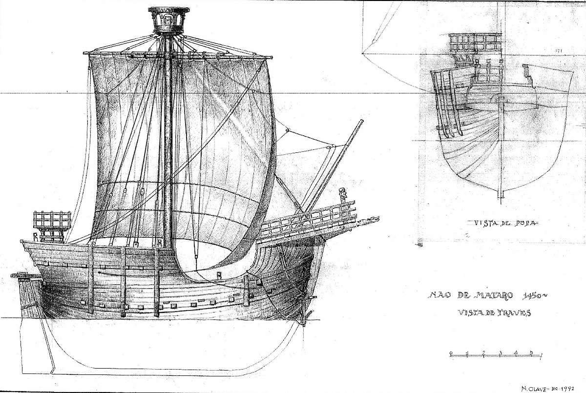
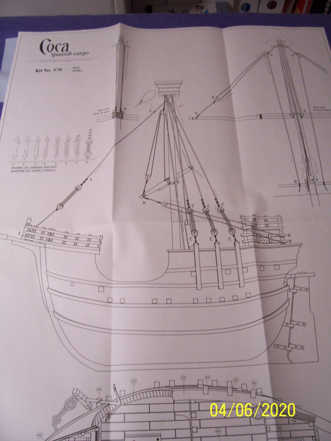
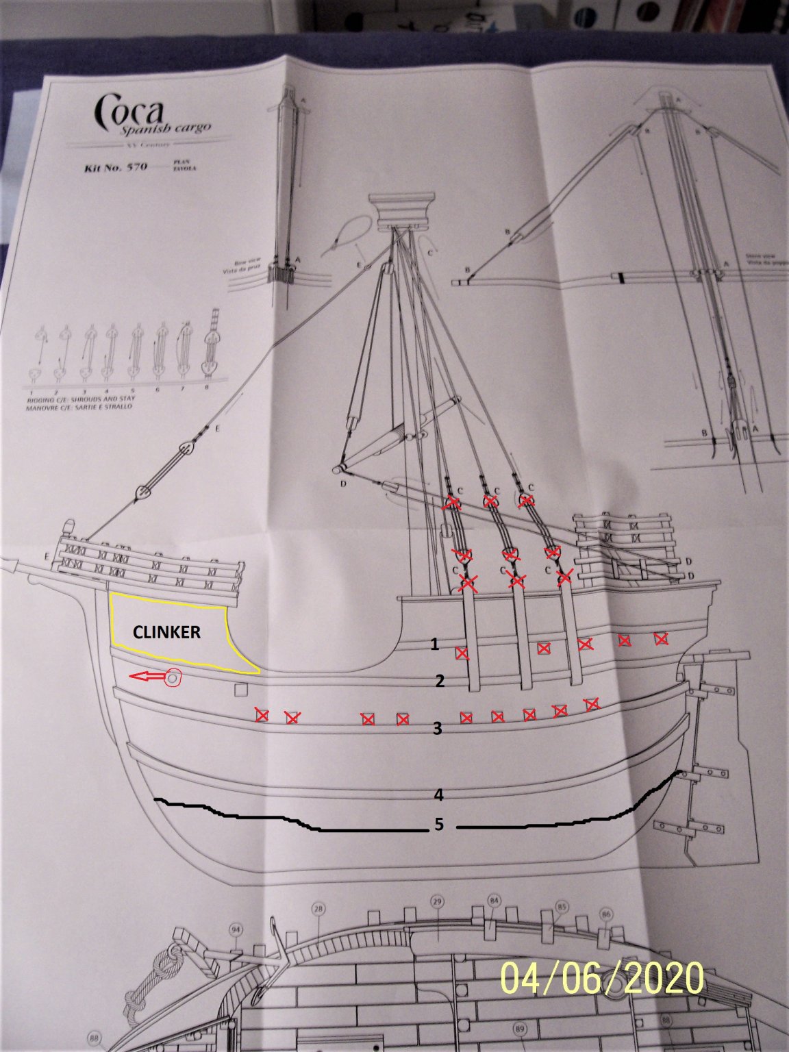
After examining the plans and looking for images of contemporary boats, I decided to make some changes:
1) the hawse hole have to be moved forward.
2) the yellow marked area will be "clinker working".
3) the upper beams will have a smaller section, differently positioned and will be more numerous.
4) the lower beams will be more numerous and differently positioned.
5) some top-timbers will be differently positioned and the number 5 will be added.
6) the frames and the bulwark stanchions will be more numerous.
7) the rigging will be totally changed: I've never seen such a disposition.
Attached are some examples that inspired me.
Have a nice evening,
Rodolfo


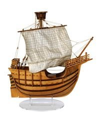


Coca by Rodolfo Bigoni - FINISHED - Amati - Scale 1:60 - XV century Spanish cargo vessel
in - Kit subjects built Up to and including 1500 AD
Posted
Many thanks, Backer.
Your pictures solved some doubts I had about rigging.
The work on the Coca has continued, ending the planking:
After that, a bit of varnish:
Under the deck I added a crossbar:
Next step will be the anchor crossbar...
See you soon!
Rodolfo