HOLIDAY DONATION DRIVE - SUPPORT MSW - DO YOUR PART TO KEEP THIS GREAT FORUM GOING! (Only 36 donations so far out of 49,000 members - C'mon guys!)
×

Rik Thistle
-
Posts
864 -
Joined
-
Last visited
Content Type
Profiles
Forums
Gallery
Events
Everything posted by Rik Thistle
-
 For touch-up work, I'm looking for a small tin (10 - 14 ml?) colour equivalent of Plasti-kote's Red Oxide 400ml spray primer (matt acrylic?). I've used Plasti-kote spray primer Red Oxide on a hulls etc for a couple of model ships .... I got it from here .... Plasti-kote 25002 400ml Primer - Red Oxide https://www.amazon.co.uk/Plasti-kote-25002-400ml-Primer-Oxide/dp/B006XBST08/ref=sr_1_1?dchild=1&keywords=plastikote+red+oxide+primer&qid=1590226003&sr=8-1&pldnSite=1 (Note: the Amazon image shows a dark orange colour... in reality the paint is closer to a medium brown with a hint of red. ) At the moment if I need to do touch-up I take the 400ml can outside and spray some paint into a small container and then dip my brush in that. It's very wasteful. I've seen some forums mention Tamiya XF-9 or Vallejo 985 as possible substitutes for red oxide but I'm not that up to speed on paint similarities. The colour match would be 'good enough' to fool the eye but doesn't have to 100% exact. Anybody have any suggestions? Thanks, Richard
- 4 replies
-
- 1
-

-
- Flirt
- plasti-kote
- (and 1 more)
-
Videos here .. https://www.youtube.com/channel/UCm6n_wgHgakEY29Zfi8owkA/videos .... including Pts 1 & 2 of the Sternwheeler assembly .... https://www.youtube.com/watch?v=lMcXEz__ikU Very tempting 😉 Richard
-
Now that is a small helicopter ...well done... https://www.interactionhobbies.com/N-Scale-Kit-Jaycopter-Helicopter-Pilot-Training-System_p_44.html I get the distinct impression that the 'hobby business' is growing, most likely due to Covid. And once the new hobbyists are hooked then there is no going back 😉 Hopefully, kit supplies etc can keep up with the growth ... generally a good problem for a manufacturer/retailer to have. It's the same with Amateur Radio.... with folks staying at home they started to look for interesting things to fill their time and it seems the Radio Society of Great Britain (RSGB) has had a large influx of new students (and thereafter licence holders). I imagine it is similar worlwide. Both model building and amateur radio lend themselves to social distancing. Richard
-
Ekis, This is one of those art pieces that I can stare at all day finding new points of interest the deeper I look. Very well done. My mind can also drift of into the village and imagine I was living and working there. It's very relaxing and theraputic ...all homes should have one! Regards, Richard
- 789 replies
-
- 11
-

-
-
I struggled a bit getting the yards parallel As BlackAdder would comment..."they are as parallel as a very parallel thing" 😉 Your build looks so clean and all parts look like they do in the manual.... can't say more than that. Richard
- 436 replies
-
- 2
-
-
- vanguard models
- alert
- (and 1 more)
-
Black anodising might do but it involves electricity , acid and a dye (black)....https://www.wikihow.com/Anodize-Aluminum The electricity and the acid increases the thickness of the natuarally occuring aluminium oxide (rust) coating and the dye fills in the pores of the oxide layer. This gives the aluminium a very hard surface finish and a reasonably black finish. But it won't be the blackest of blacks, IIRC. There may be more benign ways of getting a black finish though that other members can recommend eg spray painting? Regards, Richard
-
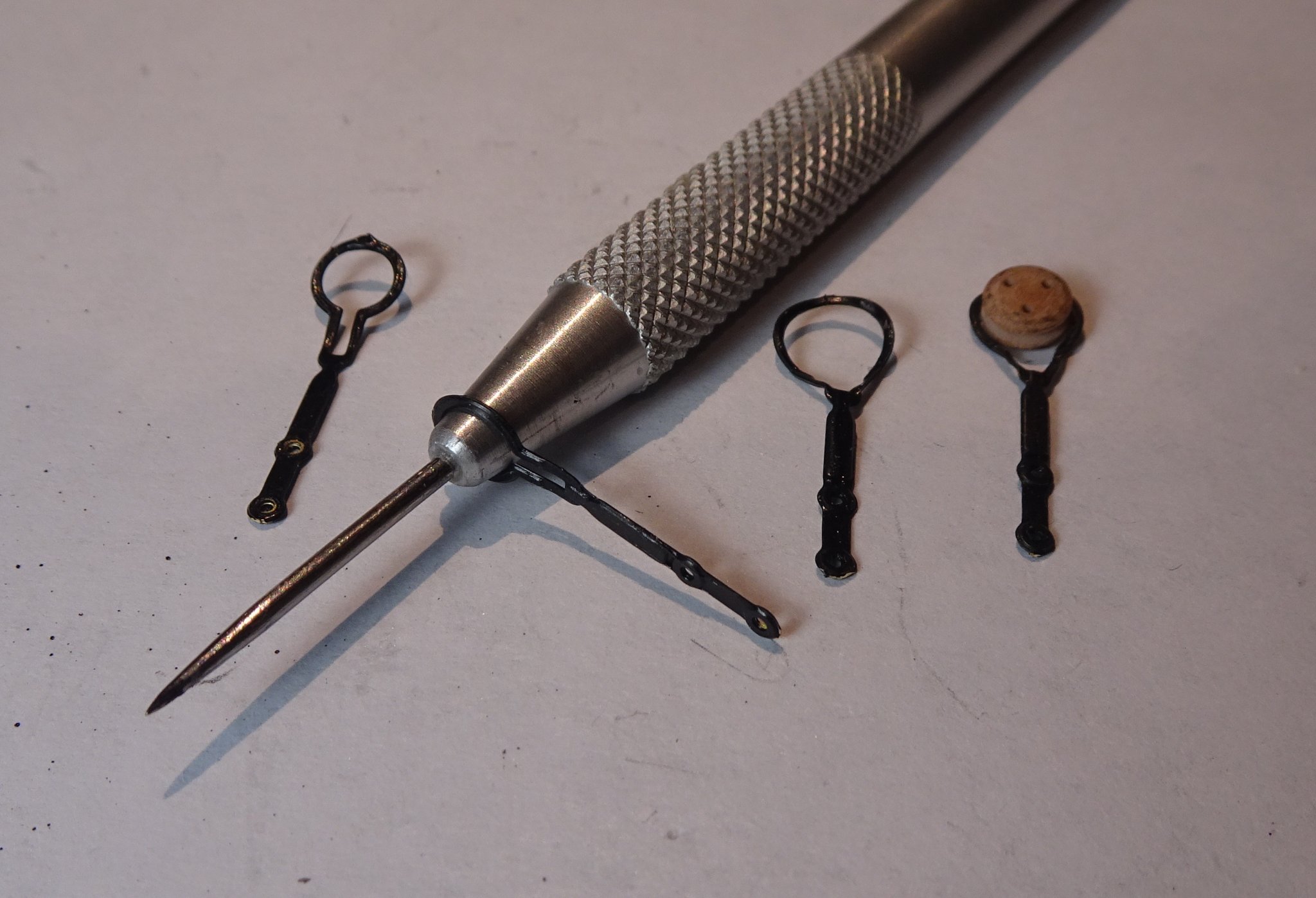
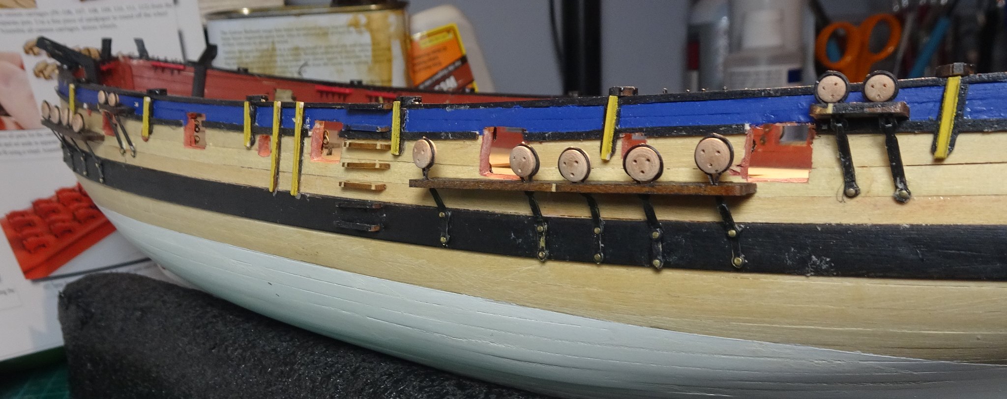
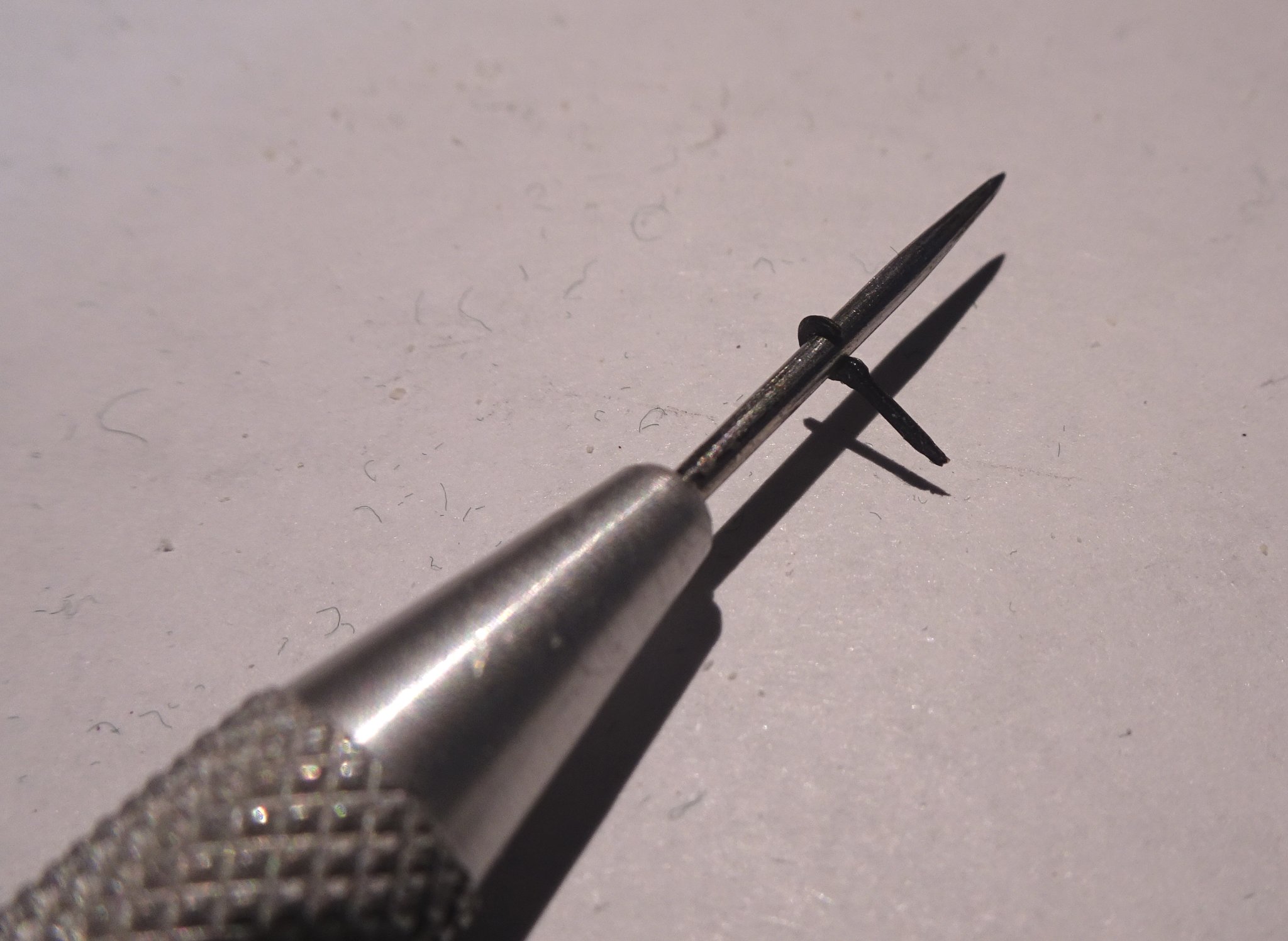
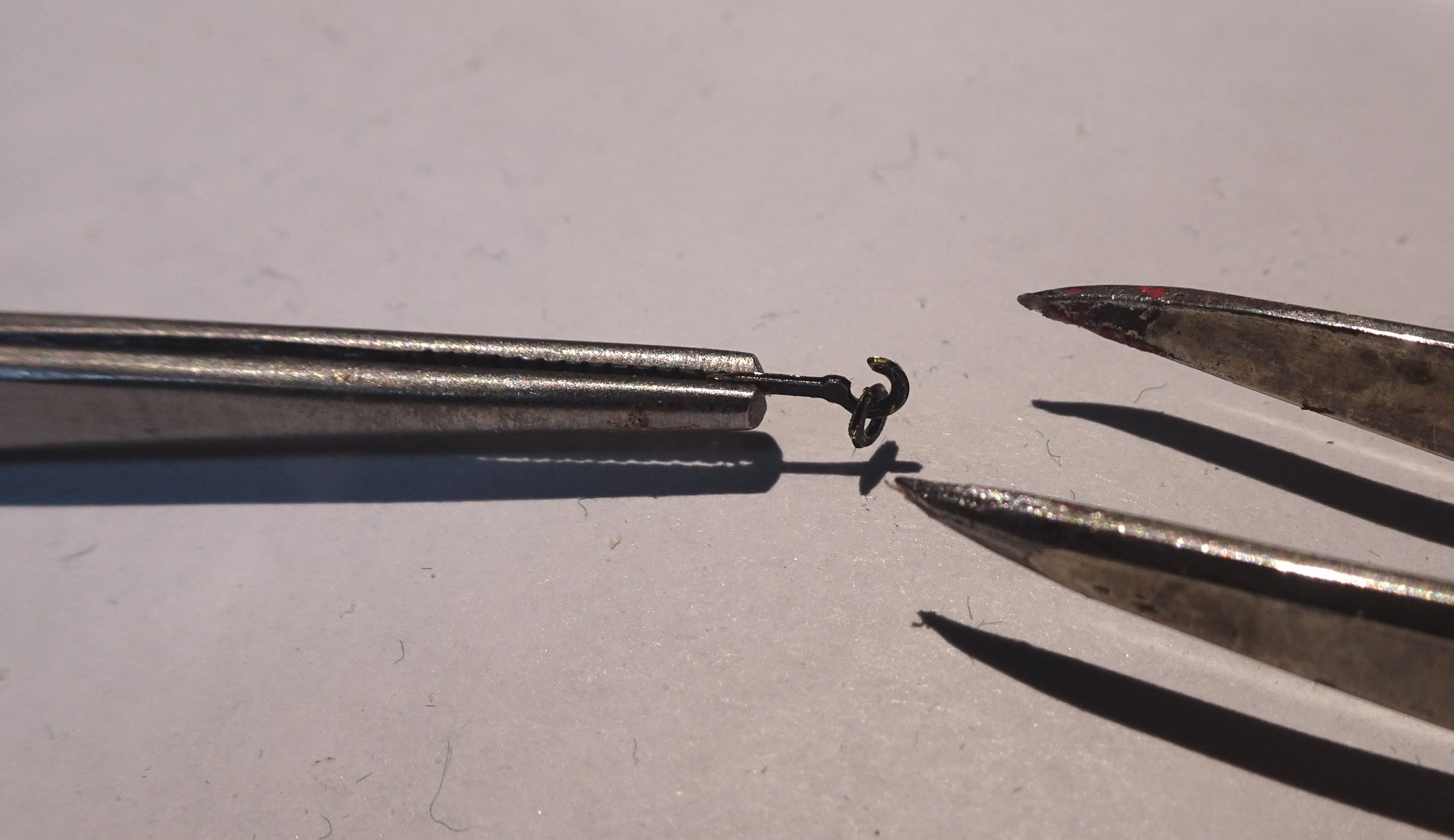
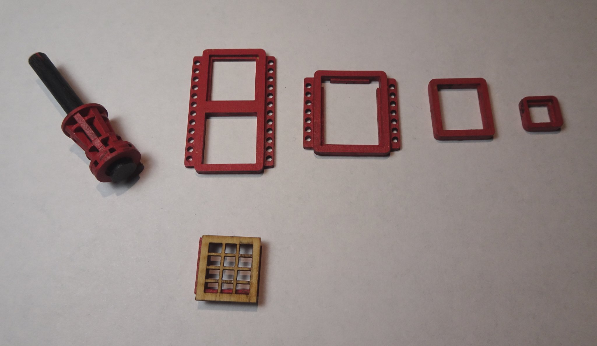
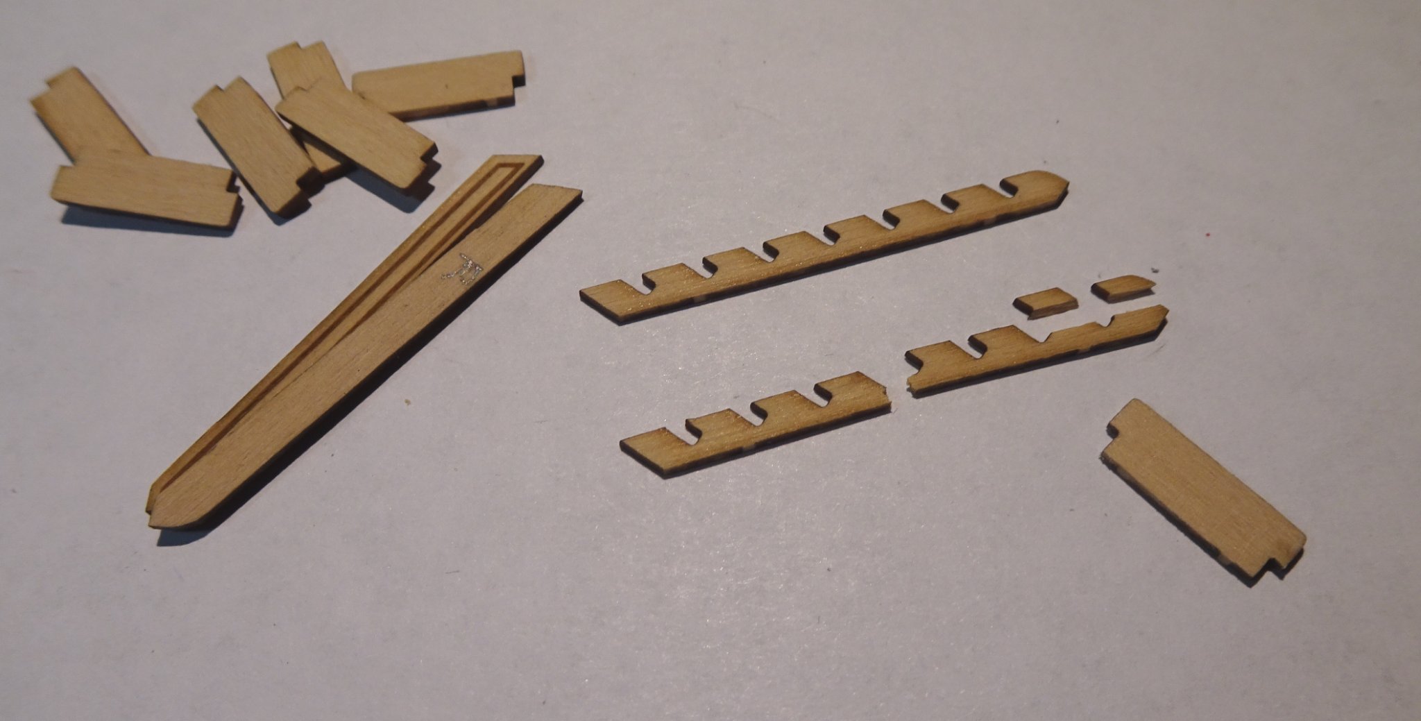
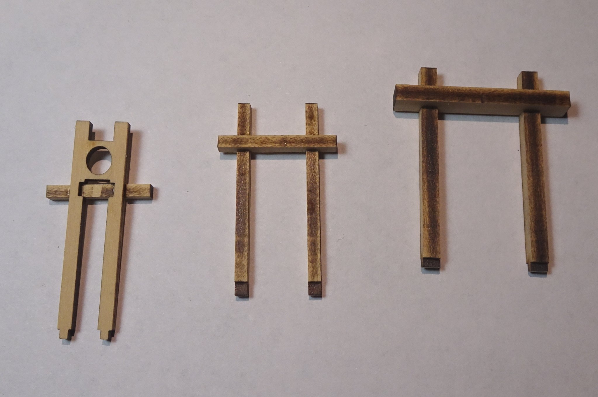
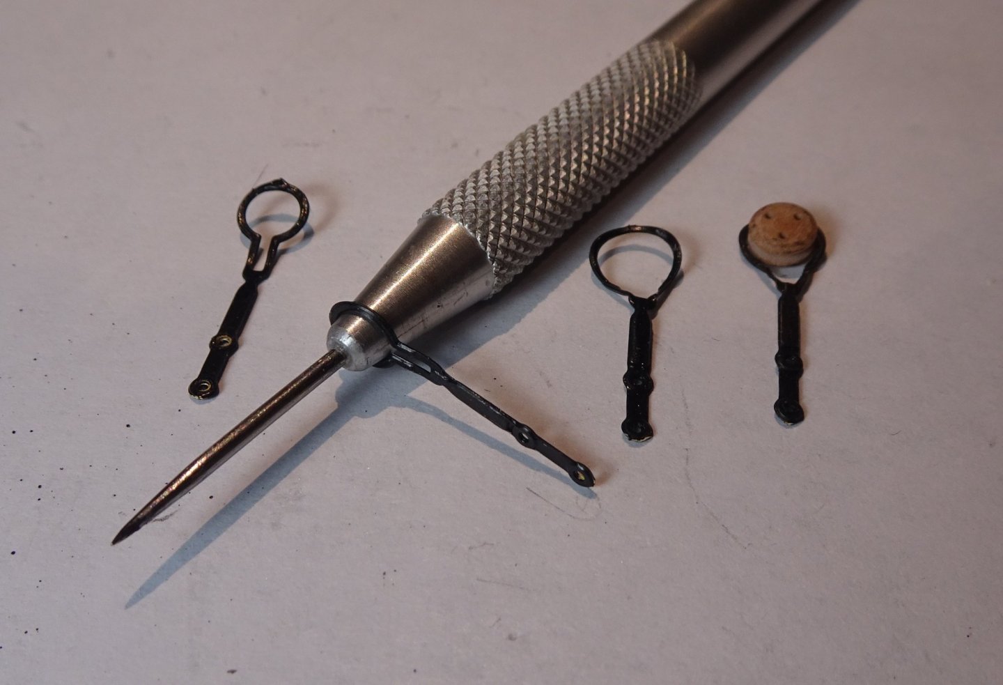
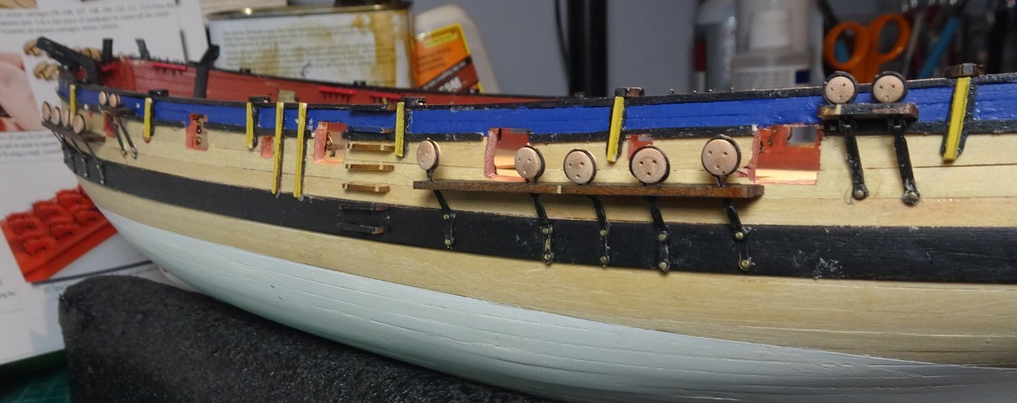
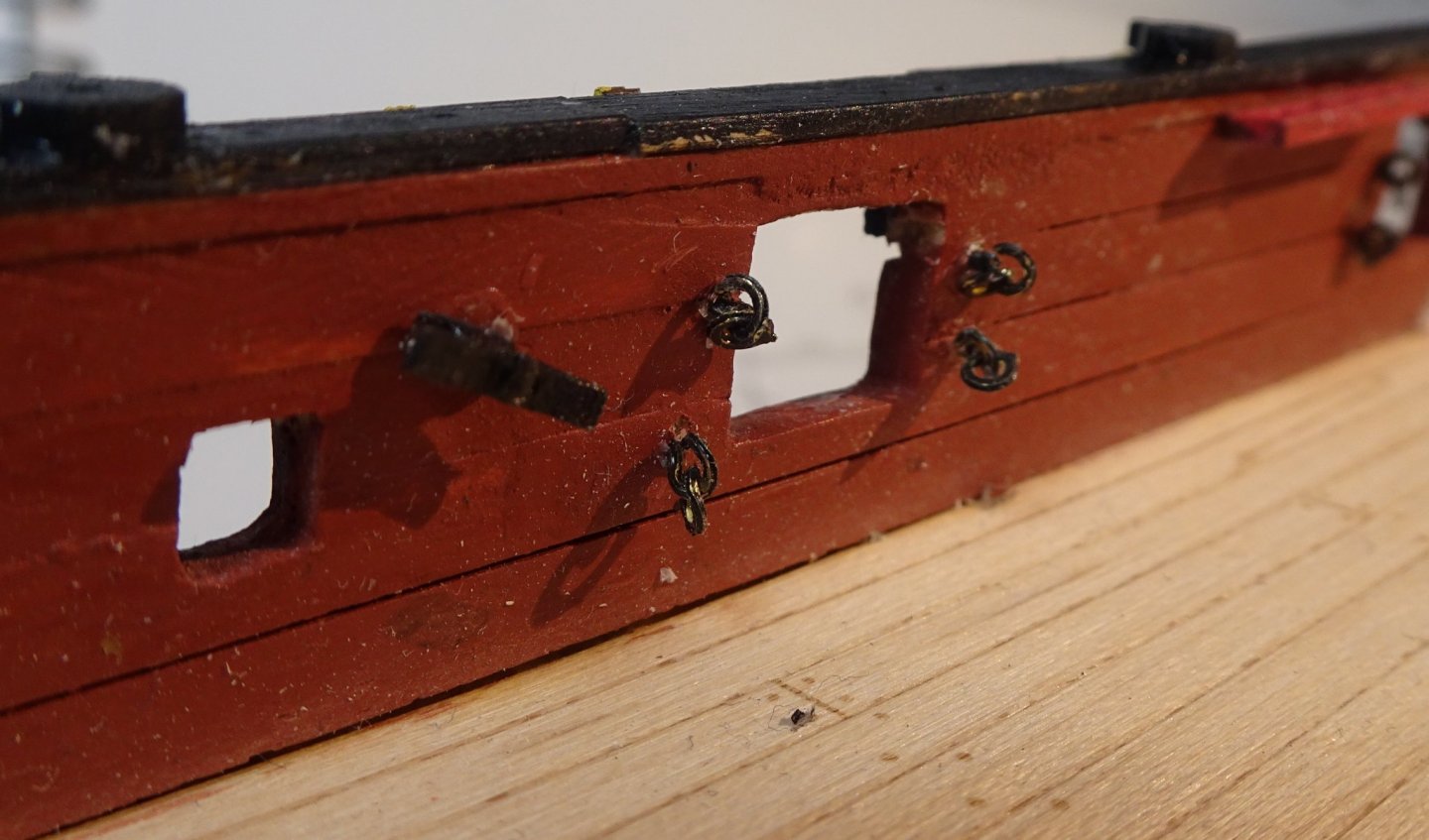
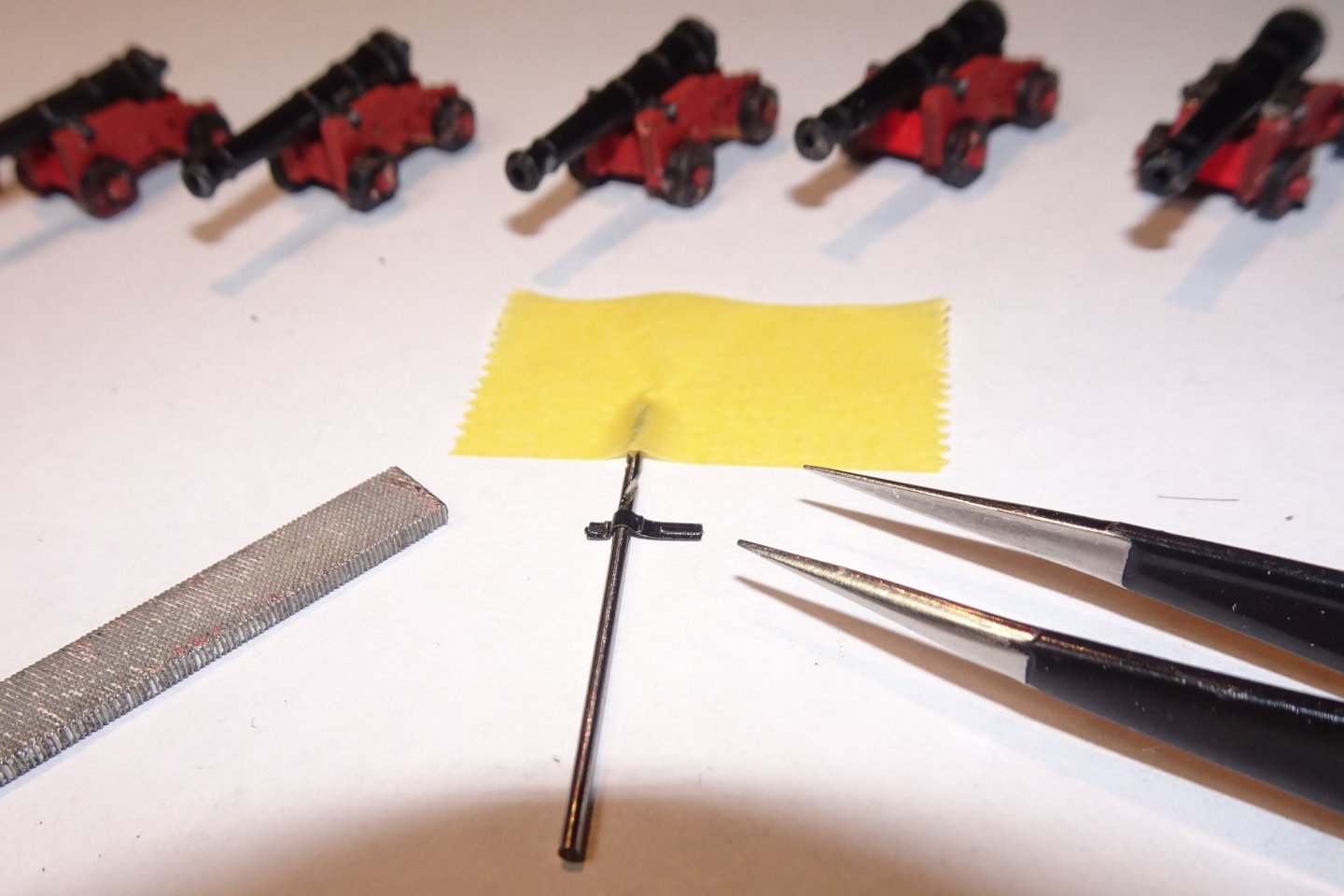
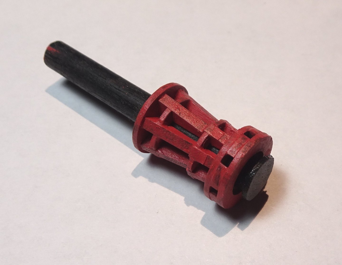
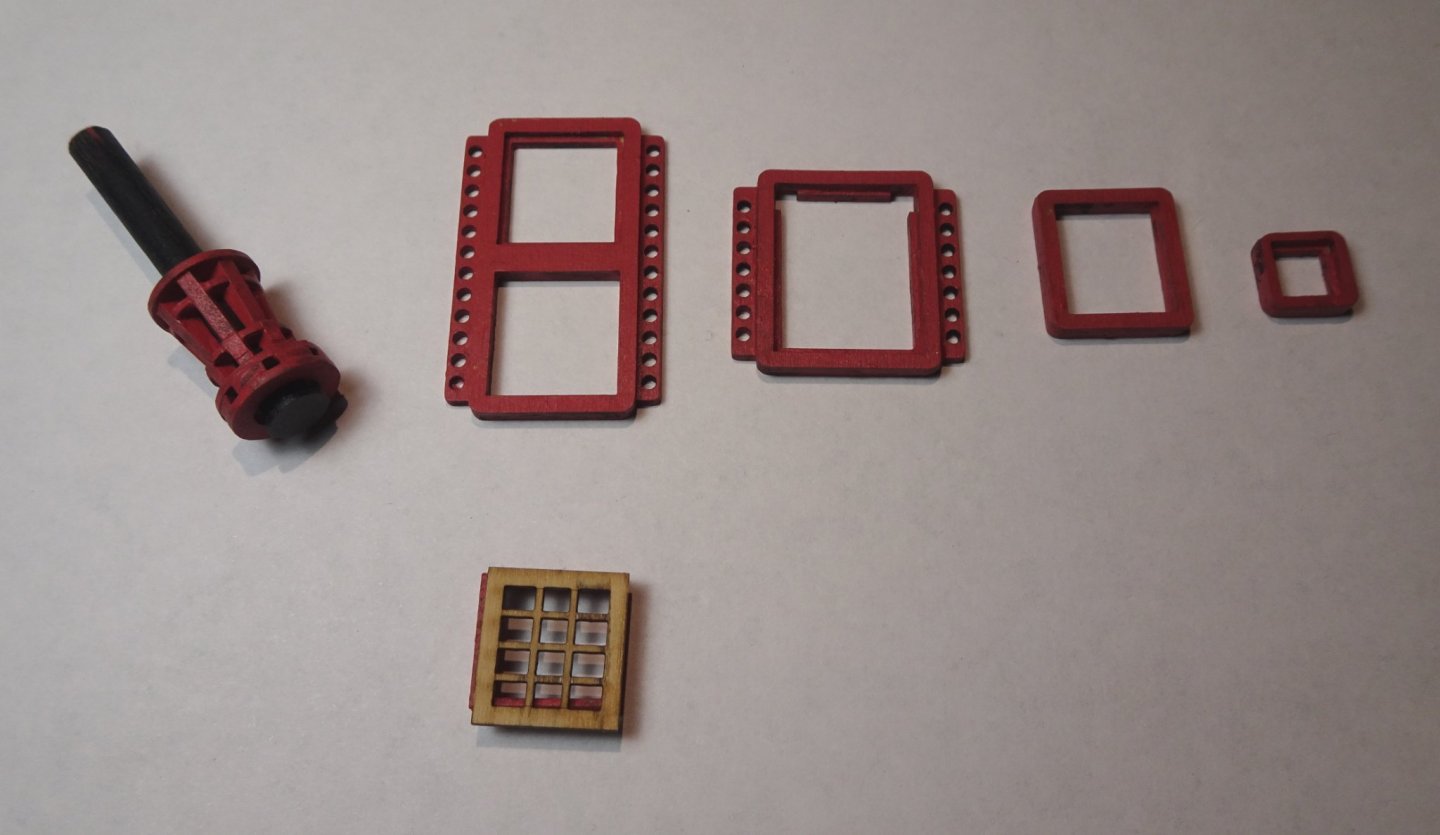
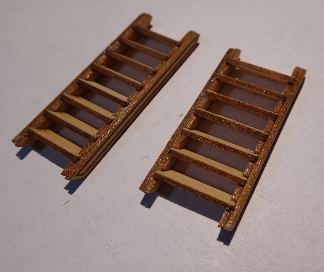
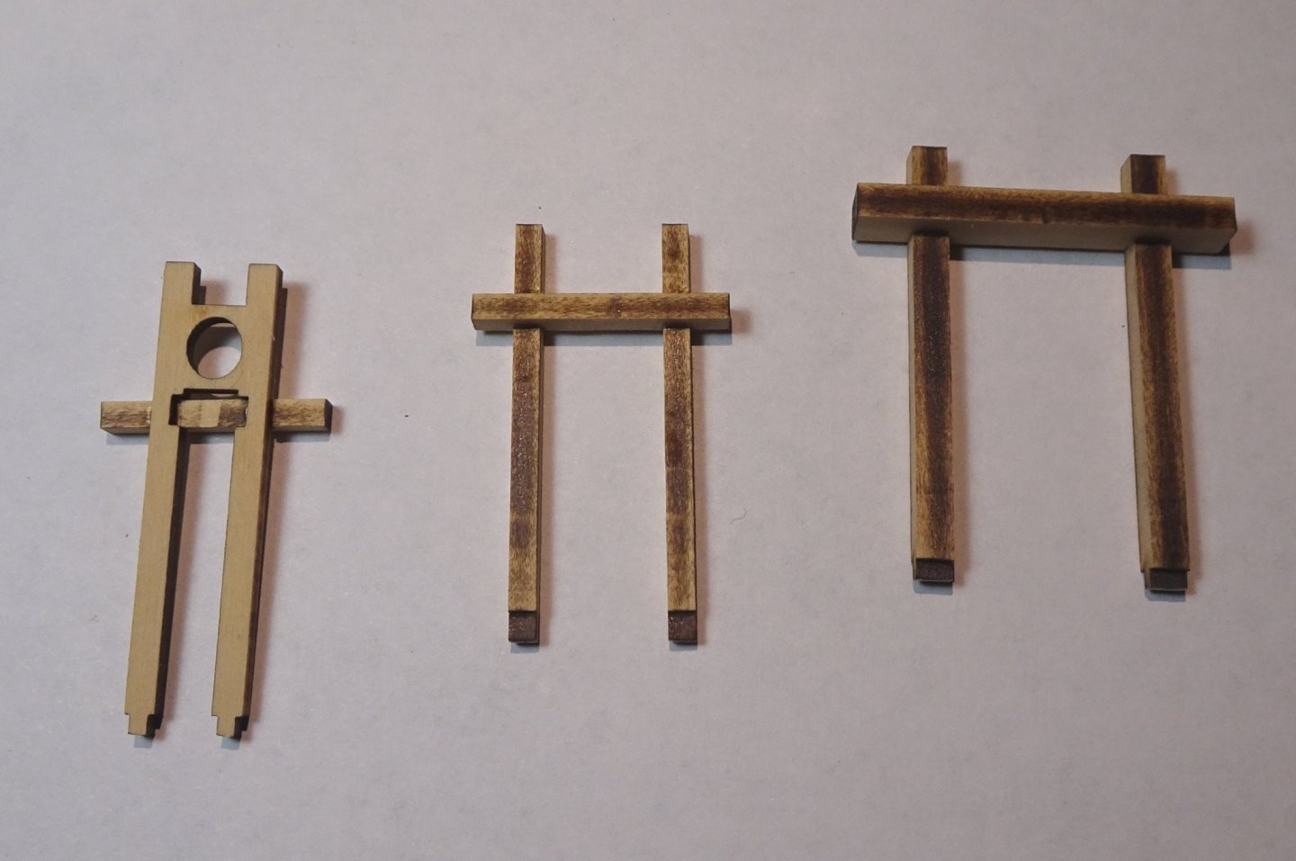
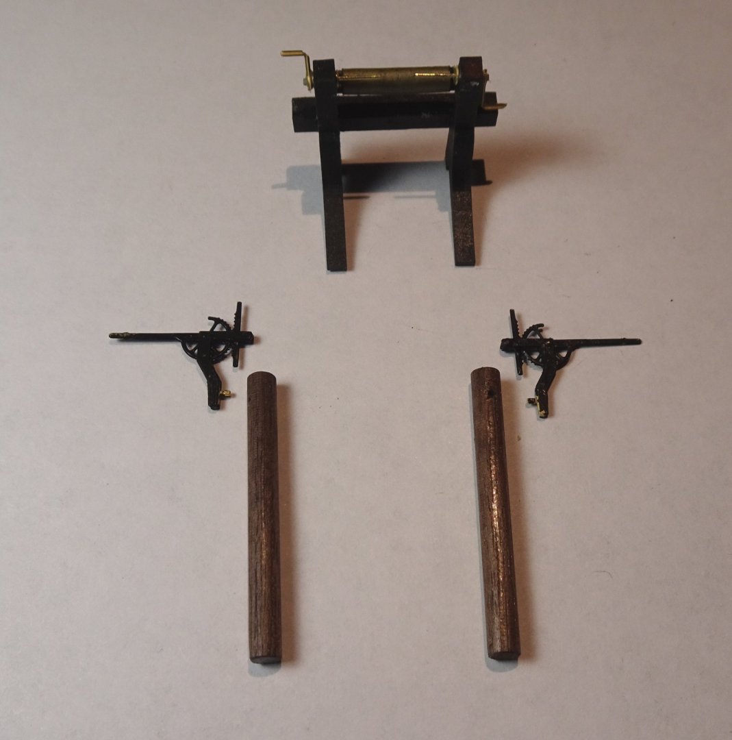
Hi all, Just a minor update on lots of Flirt small parts. Firstly, stretching the strops to fit the deadeyes. Find something with a suitable taper, then subtly ram the strop on 😉 Then close the strop over the deadeye with a pair of fine long nosed pliers. A bit crude but it mostly worked. Deadeyes and strops being fitted to the channels etc. Lots of touch-up paint still to be done in various places. And opening up the eyebolts to accept the rings. I needed my magnifying glasses to get the rings onto the eyebolt hooks. And then closed the hooks with long nosed pliers. Some of the eyebolts+rings installed. Many more on the deck also. The canon caps were bent over a 1mm drill before gluing onto the assembled canons. All 14 canons have been completed and are eagerly awaiting some action. I don't have the heart to tell them that will likely be quite a few weeks away. And the finished capstan. It went together fairly well once I had worked out the best gluing sequence, and used the dowel as a pro-forma to try to keep the capstan parts concentric...the dowel was removed when the glue got tacky, rather than letting the parts stick permanently to the dowel. Hatches etc done. Nothing to see here...let's move along... And then there were the ladders 😉 I found the steps way too fat to fit into the laser etched cut-outs with the resulting mishaps shown below. However, after sanding down the thickness of the steps, and with some careful gluing of the broken ladder parts plus using the Outer Side as a support, the issue was quickly resolved. Finished ladders. Posts etc. And finally, the windlass and pumps. Not a super interesting post I'm afraid....more of a record of where I've got to so far. And it's been about 3 weeks since I last posted, which is almost long enough for me to forget any useful comments/observations I would have thought about at the time. So best get something posted now before it's too late. Hope you are all surviving the new year and keeping safe. Regards, Richard


-
I have too many vices. 😉 I used to! ...those were happy days. Bruce, thanks for the vice info - only thing is that that handle is long and needs 'pushing through' every 180 deg turn....that's why a thumbwheel type handle is preferred for my application. Anyway, I think I've now got enough to go on. Thanks again, Richard
-
Hi BE, The little boat is looking very good...I've got one in my Flirt kit so your build is timely and useful. A question on vices, if I may... I'm looking for a small (100mm x 80mm vaguely), free standing, weighty, non-suction, single thumbwheel screw for closing the jaws, quick to deploy vice. I'd also like the jaws to be reasonably square and flat. It will be used for quickly gripping small items, with the vice held by one hand and the tool in the other hand. I already have a Stanley ... https://www.amazon.co.uk/gp/product/B001HBS0I0/ref=ppx_yo_dt_b_search_asin_title?ie=UTF8&psc=1 which is very good but large'ish and needs taking out of the drawer and screwing to the edge of the bench ie slow to deploy The other vice I use is .... https://www.amazon.co.uk/gp/product/B089K4LFR8/ref=ppx_yo_dt_b_search_asin_title?ie=UTF8&psc=1 which is almost ideal in size and weight and deployment speed but very poorly made eg the jaws are sloppy and they have a 2mm chamfer on their top edge (eh?) I notice in your pics you alternate mostly between two bench vices - a Proxxon and a die cast (?) bench-drill one ... I'm assuming one has a larger jaw opening and the Proxxon (with it's suction cap) allows larger forces to be used on the work part? So, to the question....I'm curious as to the make etc of the die cast one you use and if you'd recommend similar? I've not done any research yet myself but seeing your pics reminded me this was on my To Do List and that I need to get on it😉 Regards, Richard Edit: This (although a bit pricey) might do the trick ... Proxxon 24260 Bench Vice https://www.amazon.co.uk/PROXXON-24260-Proxxon-Bench-Vice/dp/B000S8HPLG/ref=pd_all_pref_5?pd_rd_w=5xuwm&pf_rd_p=0b287dfd-17bb-473b-878d-27964fab82e6&pf_rd_r=4R1ASHNX0PY839T00QTV&pd_rd_r=24828407-f4db-43c5-b2da-554bed2880e5&pd_rd_wg=qQkRp&pd_rd_i=B000S8HPLG&psc=1 I'll leave it at that since I don't want to hijack this thread 😉
-
Neil, Thanks for that. I'll have a look. I've also revisted FlyingFish's Orca build log, which I'd forgotten I was 'Following'. I'll now keep an eye on both builds for if/when that day comes. Richard
-
neilm, Your Orca is looking great. The film Jaws brings back a lot of fond memories - was it really 1975!? ... https://www.youtube.com/watch?v=2I91DJZKRxs I've never done a scratch build but, one day, hope to. Orca could be the one. Can I ask if you used these plans .... https://www.cornwallmodelboats.co.uk/acatalog/mar2463.html ... and does a scratch builder buy two sets of plans, one for reference and one for sticking to the wood and then cutting? regards, Richard
-
Hi Guy, I tend to spend most of my working time sitting down, but use a chair that rotates and has wheels so that I can move easily to different 'stations' on my U shaped work bench. It's only when I need to do sanding or spray painting, say, that I stand up and move to a place (garden shed) where the dust/fumes won't drift through the house. Some MSW members use extractors to get rid of dust/fumes. In the middle of the U is where I work on the ship, to the right is a tray of 'most used tools' and my computer (for reading MSW etc) and to the left is a mishmash of instruction booklets/plans and a tool drawer. Good lighting is important - I use an angle poise light fastenened on to a shelf, as are a couple of smaller IKEA clip-on lights. On the subjects of shelves...you can never have too many 😉 Hope that helps a little. Regards, Richard Edit: A relative use crutches and he has strong arms and uses either the chair he is sitting in to lift himself up or the table he is facing. If using the table it needs to be sufficiently well built to take his weight.
-
I've just received The Oxford Companion to Ships and the Sea, hardcover version from amazon.uk for £6.65. It is the 2005, 2nd edition and looks brand new and unopened. I will leave it lying in the shed for a few days before handling it. Thanks, Richard
-
I've bought the 2005, 2nd edition, hard copy from amazon.uk prime for £6.65...received it 10 mins ago. It looks brand new and never been opened. I find reference books easier to read since I don't have to commit to reading the full book over a certain period....I only need to read the bits I'm interested in on any particular day 🙂 The book will first spend a few days in the 'decontamination ward'. Thanks for the heads-up. Richard
-
I see that there is a refurbishment program underway for the replica HMS Surprise in San Diego ... HMS Surprise: Then and Now (Master and Commander) https://www.youtube.com/watch?v=eyTJaW6JcA4 ... The video mainly focuses on replacing the 50 year old decking with a new type of decking material that is more watertight. Richard
-
B.E., Producing a PhotoBook is a very nice way of finalising the whole build procedure. I have used VistaPrint (a few years ago for other items) and also found them very efficient. I don't think my ship building efforts so far warrant a photobook 😉 ... cough...but I can think of some other ventures that myself and friends have undertaken that could benefit from a memorial photobook. Food for thought. I imagine the layout of your Fifie/Zulu book takes quite a bit of careful thinking and planing. Maybe a build log of that?.... he says only half joking 🙂 Anyway, your book looks absolutely superb as, of course, do the models. It's the kind of thing that would sell well at conventions and in clubs, when we get back to normal. Thanks, Richard
- 261 replies
-
- 4
-
-
- muirneag
- vanguard models
- (and 2 more)
-
I recently started reading the series of books. The podcasts explain some of the finer points that flew over my head. Also having a precis of the storyline(s) helps me understand the reasons behind the twists and turns of the plots. Richard
-
She's looking very sharp and clean lined. The 'hinged' windows are a nice touch. Richard
-
"... two small brass ports in the deck.... I immersed the part in the brass blackening solution....the bolt marks stayed a nice bright bronze color.... a small air bubble must have formed at each of the bolt marks, " That's an interesting one. Did it happen on both brass ports? The 'held in the hand' pics are really good, and out in the sunshine too :-) The different wood colourings and the fittings are combining very well. Richard
- 222 replies
-
- 2
-
-
- First Build
- Lady Isabella
- (and 2 more)
-
drjeckl, Ref your #1 post, Learning for me, as a fellow noobie, is a huge part of this hobby. I've bought a few books (hardcopy and Kindle) on various 'ship' topics and am slowly working through them in a haphazard fashion. I've also watched numerous YT videos and been the grateful recipient of loads of advice from the members on here. I think I've now reached the stage where my brain is spinning with all the info received and therefore need to take a step back to try to see the big picture, and then how to arrange my learning steps in a more methodical fashion. Problem is, there are so many interesting ships to construct that my 'next project' selection is likely quite random which means I jump from one unknown to another unknown. I think we not only need to learn/enjoy how to assemble the kits (wood shaping, gluing, painting etc), we also would like to understand (I assume) how ships 'work'. If you've got nautical experience then that second point probably comes naturally through previous training. But a lot of us don't have that basic training. I build a Dallas Cutter in the summer...it had plenty of rigging (at least for me it did) and I just followed the kit's instructions on how to rope it. It was only a few weeks after it was built that I stood and stared at it and started to follow each rope from it's start to where it ended up and what it's likely purpose was. I found that very enlightening ...I'm an ex-mechanical design engineer so enjoy trying to see 'how things work'. Today I'm watching ... Handling a Gaff Rig https://www.youtube.com/watch?v=K9_L-VGSbwct as part of my new self-designed basic training 🙂 And I am also searching for similar videos. Books are fine but a (moving) picture tells a thousand words. Question to all - does there exist a reasonably simple, learning ship kit with rigging, sail(s) etc that are actually fully functional ? For example, if I want to drop one of the sails I undo a rope(s) and lower the sail then tie the rope up with the correct knot etc. I could even take the learning ship out in to the garden and watch the effect the wind has on the sails as I adjust them, and the corresponding forces on the hull. Richard
-
http://modelexpo-online.com/assets/images/model_shipways/longboat5.jpg As some one with very limited nautical knowledge I'll have a go at the 2021 quiz... - the oar looks a bit short - is the mast fully supported at it's base - it's more likely something to do with the rigging, I guess, but there I'm out of my depth Richard
-
Bob, I think white below the waterline, but it's a very close call. Either will be spot on, but the white would catch the eye more from a distance. Richard
-
VTHokiEE, Gunther, Bob, I have tried full quotation marks around MSW phrases in the past...as I sometimes do on other search engines....but hadn't had any luck. I also have tried inverted commas at the ends of the phrase but again no luck. Maybe "drifter steam capstan" was a bad example to use since no one on the forum had actually ever used that particular phrase, until now. Maybe I have to carefully consider what phrases are more likely to have been used on MSW before searching for them? But I've just tried the victory rigging seizing phrase with no results....and victory seizing...no results. It might just be that these 2 or 3 word phrases, in that order, have never been used. Bob, yes, sometimes when on Amazon.uk, I'm searching for a product using the Amazon search box and nothing shows up. So I come back out in to Google and type "product X amazon" (...no quotes) and Google shows a link result to the product on Amazon.uk, so I click on the link and it takes me straight to the product on the Amazon.uk website. Strange - you'd think Amazon of all companies would have a 100% effective search engine...but they don't. The MSW website, by the way, is the best forum I've been on so the above is more of an observation than a criticism. But there is so much useful info on the website that I wonder if there is a way to weedle out even the most obscure search enquiry? Richard Edit: I've just noticed I spelt 'drifter' as 'drfiter' in my original post...well, that wouldn't help 😉 New Year Resolution - spell check what I write .... hmm, now there's another thought...
-
On the subject of using the Search function on this excellent website, is there a way to search for exact phrases eg 'drfiter steam capstan' and only that complete phrase. If I search for that phrase it seems to be treated as three separate words eg drifter, steam and capstan ...with the resulting long list of results usually containing one or two of those words only but not the exact phrase. I've maybe missed the way of doing phrase search selection in the instructions so apologise in advance. Richard
-
Bruce, Mine arrived today. I am totally satisfied with the solid construction and the range of the movement. I probably won't use it for blacksmith-stle jobs but it really does look a lot tougher than I expected. Yes, it's a good value buy. Reminds me of when products did what they said on the tin. Agreed, I wouldn't use it to file/saw 1" steel bar but 1/4" sized then it's fine. But it really comes in to it's own for fettling small items that need to be held at weird angles. And it deploys very quickly. I made the mistake of using it as a soldering jig whilst the soft jaws were in place...well, plastic and soldering irons don't mix too good 😉 I'll get round to ordering new jaws some day soon. Enjoy using your new acquisition. Richard